ST 3256 P - Snow blower STIGA - Free user manual and instructions
Find the device manual for free ST 3256 P STIGA in PDF.
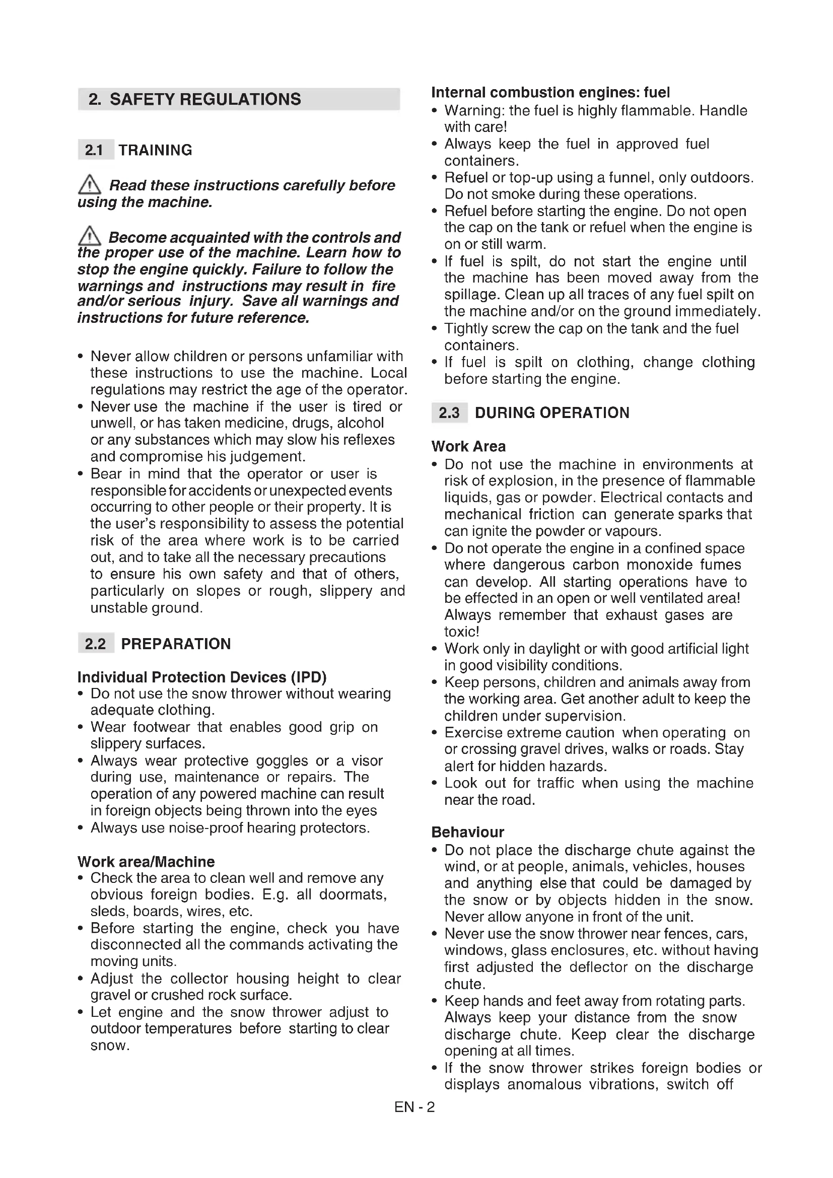
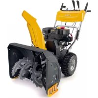
| Product type | Walk-behind snow thrower |
| Brand | STIGA |
| Model | ST 3256 P |
| Clearing width | 56 cm |
| Maximum snow height | Approximately 30 cm |
| Engine | 4-stroke gasoline |
| Starting | Manual (recoil) and electric (230 V, optional) |
| Transmission | 5 forward speeds, 2 reverse speeds |
| Chute orientation | Manual by knob, 180° rotation |
| Deflector | Height adjustable by lever |
| Lights | Optional |
| Fuel tank | Capacity not specified |
| Engine oil | Periodic oil change (see manual) |
| Safety | Ignition key, engine stop, protections |
| Weight | Approximately 80 kg |
| Dimensions (L x W x H) | Approximately 60 x 70 x 60 cm |
Frequently Asked Questions - ST 3256 P STIGA
User questions about ST 3256 P STIGA
0 question about this device. Answer the ones you know or ask your own.
Ask a new question about this device
Download the instructions for your Snow blower in PDF format for free! Find your manual ST 3256 P - STIGA and take your electronic device back in hand. On this page are published all the documents necessary for the use of your device. ST 3256 P by STIGA.
USER MANUAL ST 3256 P STIGA
EN Pedestrian controlled Snow thrower - OPERATOR'S MANUAL WARNING: read thoroughly the Instruction booklet before using the machine.
6. USO DELLA MACCHINA
HnnaparpaCn ca ot6eJ3aHn CbC
cbkpaeeHneTo "rI." Hn "nap." nCbOTBeTHn
Homep. Hanpimep: "rI. 2" Hn "nap. 2.1".
1.1 KAHДA CE YETEPbHOBOdCTBOTO
B TeKCTa Ha pBkoBOODTBoTO, HrKoI npaparpaH, KOHTO CbDpKaT OcO6eHO BaXHa HΦopMaun 3a 6e3OnaChocTTa Hn ΦyHKuONHpaHeTo, ca OTBeJra3aHn NO pa3JIueH NaHH cNoped CLeDnH KpITepN:
БЕLEЖHA BAXHO npedoctabnyTOUChHnI INIpyrN eIeMeHTN NOOTHOWeHHe HaIHTnpaHOTo No-rope, CcEJaCe H36erHe NOBpeJdaHe HaMaunHaTn HAHaHcAHe HaIeTn.
CnMBoJbT nKa3Ba onaCHOCT.
Hecna3BaHeTo Ha npedynpeXdeHneTo
BOdN DO Bb3MOxHOCTTa OT IINHH
HaPahraBaHnI HapaHbAHHa
TpEtN Iuca N/Inn HaHaacHe Ha 8eTI.
NaparpaΦte OT6eJIaHc KBaIpaT CbC CNB TOUKO B KOHTyp, yKa3BaT ONUHOHaIIH XapaKTePncTHn, KOITo He ca npDeBnDEHN 3a BCnKN MoJeIN, ONuCAHN B TOBA pBkoBOdCTBO. IpOBepTe DaII N CBOTBeTHaTa TexHuecha XapaKTePncTHka e npDeBnDEHa 3a Baunr moDen.
Bcunyka3aHn“npedeH”,“3aH”, “Decen"N“JIb”ceOTHaCrt3aOpeatopB IPOLOKeHne 3a ynpabLeHne HaMaunHaTa.
1.2 CπPABH
1.2.1 Φιγρη
ФИгурптЕВ Te3n INHCTpyKUIN 3a eKcNlOaTaCua Ca HOMepnpaHn 1,2,3,N T.H..
KOMnoHENTe NOCOueHn HaФИгурптЕ ca OT6eJIa3aHn C bYKBInTe A,B,C nT.H.
CnpabKaTа 3a KOMnoHENTa CHa
ФИгура 2 ce NOCOuBa C NaDnica:“Bx.
ФИг.2.C" Ил npocTo "(ФИr.2.C)".
ФИгурптЕ ca INHdNKaTHBn.ДeиCTbNTeJHnTE
чacter MoKe Da ce pa3JIuYaBt OT Te3n,
KoITO ca NOKa3aHn HaФИгypaTaN.
1.2.2 3aIabna
PbKOBOCTBOTO e pa3dJeHo Ha rIaBN n naparpaΦn. 3aIaBHeTo Ha naparpaΦ "2.1 O6yehne" e np3aIaBHe Na "2. IpaBnla 3a 6e30anacHocT". OTHACHNrTa Do 3aIaBn
2. ПAPВИЛА 3A БЕЗПАСHОCT
2.1 OБуЕнгE
Ipooyete BHHMaTeJHNO HactoHTe HHCTpyKuN npedn Da N3No3BaTe MaunHaTa.
Pa3yete n CBHKHeTe C KOMaHnTe n c NOxOJUTo H3NoJ3BaHe Ha mAsHHata. HayeTe ce da N3KIOUbATE 6bp3o DBrarTeJI. Hecna3BaHeTo Ha npEynpeHdEHNrTa u HHCTpyHcNtE MoHe Da npuHHn HnUdENTn HnCepNo3Hn HapAHBaHn. 3ana3eTe BCnHn yNbTbAHn n HHCTpyHcNn 3a 6bdeu n CnpabKn.
- HnKora He No3BOJBAIte MaunHata Da 6bDe n3NoJ3BaHa OT Deca Nn OT Xopa, KOINTo He ca 3aNo3HaTH DoCTaTbUHO C INHCTpyKUnITE. MeCTHNTe 3aKOH MoKe Da npEdBnKDaT MmHmAlHa Bb3pact 3a npaBO Ha n3NoJ3BaHe.
- Aa He ce N3NoI3Ba HNKORA MaunHaTa, aKO NOTpe6nteY eymopeHnHepa3noJoxKeH, nH e npHe IekapCTBa, hapKOTnCn, aKoXoN nn BpeHN 3a peFleKcnte N BHMaHneTO My BeuecTBA.
He 3a6paBnTe, ye onepaTopbT nIu To3n, KOHTO n3noJ3Ba MaunHaTa e OTROBOpEN 3a HnUdEHTn HEnpeDbNdeHn CNTyaCnn, KOHTO MORaT Da Ce Cnyat Ha dpyrXopa nn Ha TAnxHa CO6CTBeHOCT. Yact OT OTROBOPHOCTTa Ha NOTpe6nteJ e npaeHHata Ha Bb3MOHNHe pNCKOBe Ha TepeHa, NO KOHTO Tp6Ba Da ce pa60Tu, KaTO n B3EmaHTo Ha BCNUnpaNa3Hm MepKn, Heo6XoDMn 3a rapaHTnpaHe Ha HeROBaTa 6e3OnaCHOCT n Ta3n Ha DpyrInTe Xopa, Oco6eHo, KORATO CE pa60Tu No HAKLOHn, HepaBHn, Xlb3raBn IIN HeCTa6NJHn TepeHn.
2.2 IPEДВAPITEJIH NOEPAUHN
JIuHn npedna3Hn cpectBa (JIIC)
-Да He ce n3noJ3Ba CHEROpHa, aKo He ce Hocn noXOJaPo pa6ToH O6JIeKnIO.
- Da ce HocrT 06yBn, KOHTo N03BOJRAbT DObpo 3axBaUaHe Bbpxx Xlb3raBn NOBbPxHOCTN.
Ja ce HocT BnHaN IppeDna3Hn OuHa nI INI ppeDna3Ha MacKa No BpeMe
Ha N3NoJ3BaHeTo, NOdRpJHKKaTa
N3BbPwBaHeTo Ha NoppaBKn.
FyHKcHOnHpaHeTo Ha MOTOpn3npaHn
MaunHMoKe Da npedn3BnKa
N3XBbPJIHe Ha yKdN TeNa, KOnTO
MOraT Da nOJaHb T B OHTe.
- Dacé HacrT CnywAaHn npOTNB Wym.
Pa60tha 3oHa /MaunHa
-Поберяbaitedo6pe30haTЯ
nouchTeTe nOTCTpaHete eBeHTyaJIHn
BdIMn YuKdN TeJa. HanpImep
n3TpBaJIKN,WeHN,Macn,Ka6eJI N T.H.
-Прдддддддддддддддддддддддддддддддддддддддддддддддддддддддддддддддддддддддддддддддддддддддддддддддддддд徳н
-поверете дал ca n3кючehn
ВСИЧКИ KOMАнДи, KONTO 3а徳ICTBaT
ПОДВИЖНITE чACTи Ha MaшинHaTa.
- PerylnpaIte BncoHnHaTa Ha 3aunTHnKa nak Ha uHeKa 3a NOuCTBaHe Ha HactnIKN OT YaKbJ NIN CkAJHn HACTNIK.
- Ппени за започente на риненте сега, OCTabete Двигаелги Машинаядс ce npincnocobrt KbM BbHnHaTa TemnepaTypa.
BnraTeJIc BbTpewHO ropeHe:ropnBO
- PpeDynpKdEHe: rOpNBTo e cnHbB3nIaMeHMo. Pa6oTeTe cTapaTeJHo!
CbXpaHraBaIte BnHaI rOpNBOTOBIOxOJN CbDOBe. - N3BpWBaIe 3apeKdaHETo C rOpNBO nIyDOLBaHTo Ha rOpNBO KaTO n3PON3BaTe yHnra, cMo HA OTKpITO MRCTO n He nyuWte NO BpeMe Ha Te3n Onpauu.
- N3BbpoTe 3apeKdaHTo npeDn da BkIIOHTe DBrTaTeJI. He OTbapRrTe npo6KaTHa pe3epBoapa n He 3apeKdaIte MaunHaT, KOraTO DBrTaTeJIrTe BkIIOUeH nn BCE OSe TOIbJ.
Ako n3teue ropno, He 3aeneCTbaTne Dniratae, a OTdaJeute MaunHataOT MRCTO, KbTeO e pa3JIrTO rOpNO I NOuNCTeTe He3a6abHO BcRAKaKBa CLeDa OT rOpNO Mo MaunHaTa HIN 3emra.
3aBnTe Do6pe npo6kaTa Ha pe3epBoapa NHa CbIOBeTe, B KOHTO ce CbXpaHraBa rOpBO. - N368BaIte KOHTaKT Ha rOpNBOTo C pa60THOTo 06JIeKIO H, B TaKbB Clyuayi ce npeO6JIeTe, npei 3a 3aJeICTBaTe DnIraTeJIaT.
2.3 IO BPEME HA H3IOJ3BAHE
Pa60Tha 3OHa
He n3noI3BaIte MaunHaTa BbB B3pHBOONaCHA CpeJa N B pncbCTBne Ha 3anaJIIMn TeuHOCTn, rA3OBe IIN npax. EJeKtpnueckn KOHTaKTn IIN MexaHnHn TpneHn MoRaT Da IopOJrT NcKpn, KOnTO Morat 3a 3anaJrT npax IIN napn.
He 3aJeIcTbaIte DbIraTeJIrB 3aTBOpEH npocTpacHCTBa, KbDeTo MoKe Da ce aKymyInpaT onaChn napn Ha BbIpeOeH OKcNd. 3aJeIcTbaHeTO Ha DbIraTeJI TpIbBA Da ce H3BbPbWA Ha OTkPHTo IIN Do6pe npOBetpmbO MrcTo. He 3a6paBraTe, Ye n3ropeJIITe ra3OBe ca TOKcUHN.
Pa6oTe cAmo Ha dHeBHa CBETInHa nn np Do6po n3KycTBeHO OCBETJeHne H yCIOBnHa DObpa BNIMOCT.
- OtdaJeueTe Xopa, Deca n JnKINBOTHn OT pa6oTHaTa 3OHa. Heo6xOJnMo e Deuata Da ce Ha6JIOnDaBaT O Tpyr Bb3paCTeH.
-ObpHeTe OcOBeHO BHMaHHe, KOraToCe n3NoJ3Ba MaunHaTa No aJeN OTuKbI, 6OpDOpn uYInu NIN KOraToTe3n NocLeHNte ce npecuat.BHMaBaIe 3a cKnTu ONaCHOCTn.
Korato MaunHaTa ce n3NoJ3Ba 6n3KO do nT, o6bPHeTe BHMaHHe Ha DnKeHHeTO no nT.
PobedeHne
-Да He ce opneHTnpa OTbopa Ha yIe 3a pa3TOBapBaHe cpeuBy BAYbpa NIn CpeuXopa, HINBOTHn, PpeBO3HN CpeDCTBa, HINIIua n BCNUKO Dpyro, KOEtO MOKe Da npTeTbpNn BpeDi OT Chera NIn OT npEdmTe cKpNTn B Chera. He no3BOJBAyTe Ha Xopa Da ce 3actoRaT ppeMaunHaTa.
- HnKora He n3noJ3BaIte cheRopHa B 6bn3oCT do orpaHn, aBTOMO6nHn, np03Op4n, CTbKJIeHn ORpaHn n T.H., 6e3 Da cTe peYlnpAHH NO NODXODaHauHH DeΦJIeKTopa Ha yIeH 3a pa3TOBapBaHe.
He np6nnaBaTe pBeTe n KpaKaTa Do BbptTnTE ce opraHn. CToIe BNHaN daJeOT OTBopa Ha yJea 3a pa3TOBapBaHe Ha cHr. PndbpKaHTe BNHaN YnCT yJeT 3a pa3TOBapBaHe Ha cHr.
Ako cheropnHa ydapn ChkDn TeJa nnrehepnpa HeHOpMaHn Bn6paun, n3KlOyTe DnIraTeJrT, CBaJIeTe KIOUHT Ha 3anaJIbaHeTo, N3uKaIte NOdBnKHNTE qactn Da cnpaT da ce DnKnat I pereJeTaB HmMaTeJHO MaunHaTA 3a EBeHTyaJHo NobpeJdaHe. O6NKHOBeHO Bn6paunTe ca 3NaK 3a HAnuHe Ha npoJem. PpeDi Da n3NoJ3BaTe OTHOBO MaunHaTAt, OTCTpaHete EBeHTyaJHn NobpeDi.
-Ппедида ce OTдалачиTe OT MaшиHaTa, ИЗКИючete BCИЧКИ KOMaHДи, CBaJIeTe KИIOчт Ha 3anaJВaHETO OT HEROBOTO MЯCTO Ha MaшиHaTa.
-ПпедиИЗВьршванToHa nonpaBKN, nouchTbaHe, npOBepKn, PerylnpaHnA, ИЗКЛIOчTe DBNraTeJIaT, CBaIeTe KIIIOUbT Ha 3aNaIbAbeTo И ИЗЧаKaIte,ДOKaTO NOdBИЖНITE qaCTH He ppeTaHaT Da ce DBINKaT (c ИЗКЛIOчEнe Ha pa3IInuHn
yka3aHnna, nocoueHN B pboKOBOcTBOTO). Pa3kauhe Te Ka6eJIte Ha eIeKtpnuecknra DBnrgatel. (OnuHOHaJeH)
He nnaTe yactn Ha dBnraTeIa, KOnto no BpeMe Ha pa6ota ce 3arpBaT. Pnck ot n3rapHnIa.
He n3noJI3BaIte MaunHaTa npn BncoKa CKOpOCT Ha TpaHcNOpTnpaHe NO XJb3rABn NOBbpxHocTn. BnImaBaITe, KOrato Kapate Ha 3aDen XoD. NOrJeHete 3aD Bac, npeNi IIO BpeMe Ha DnHexHe Ha3aD, 3a Da ce y6eInte, ye Hma npenTCTBna.
- DeaKTbHpaIte uHeKa, KOraTo MaunHaTa ce TpaHCnOpTnpa nn He Ce n3NoJ3Ba.
BnHaHc ce yBepaTe,Ce cHaMnpaTe Bdo6po paBHOBecHO CbCTOHN He XBaHeTe 3dpabo pKoXbaTkata. XoTe, Hkora He TuaTe.
OrpaHnueHn npn n3noJ3BaHeTo
He n3noJI3BaIte MaunHaTa HnpeHNO nHaKIOH. BnKeTe Ce BNHaN OT BnCOKOTO KbM HnCKOTO MACTO NOT HnCKOTO KbM BnCOKOTO MACTO. O6bPHeT e BHIMaHne, KOraTO npOMeHrTe NOCokata NO HaKIOH. Da ce n36rBAT CTPbMHn HaKIOH.
-Да He ce n3noI3Ba MaunHaTa, aKo 3auntTe ca HeIOCTaTbUHn IIN, aKO npEpa3HnTe yCTpoiCTBa He ca No3nUHOHpaHn IpabNlHo.
He n3KIOUOBAuTe HIN He MoNΦnIpaAte CnCTeMTe 3a 6e3OnacHOCT.
He MoDnΦuNpaTe peRyIuPOBKnTe Ha DBrAteTne Hr Ro npTeOBaPBAeTe Ako DBrAteTne pa6ToH Na ppeKaIeHo BnCOKn O6OpOTn, ce yBeJIuYBaPa nCKa OT IuHn HapaHbAHn.
He npetoBapBaTe MaunHaTa KaTo ynpabnBaTe Ha TBbpDe BnCOHa CHOpocT.
He nocTabaIte pBcTe cN B OTdJIeHHeTo 3a pa3TObapBaHe IIN B UHeKa, npEn Da CTe CBaIIIN KIOvHT Ha 3aNAIbaHTo.
2.4 NOДРьЖHA,ПРБИРАЕ 3ACbXPAHEHNEI TPAHCIOPTIPAHE
I3BbPWBaHeTo Ha npaBnHa noDpBkKa n np6npaHe 3a CbXpaHHeNe, 3ana3Ba 6e3OpacHocCTTa Ha MaunHaTa.
IIOBpeHHeNte HnHn3HoCeHn Yactn Tp6Ba Da 6bDat 3aMeHeHn HnHora Da He ce nonpaBrt. N3noJ3BaHTe cAmO opuHaJIHn pe3epBHN Yactn: H3NoJ3BaHeTo Ha HeOpuHaJIHn pe3epBHN Yactn N/IIHn HEnpaBnHO MOHTnpaHn, 3acTpaWaba 6e30NaChocCTTa Ha MaunHaTa, MoHe Da npuHHn HHnDEHTN IIN NnHn HapaHraBaHna,
KaHTo n Chema ot Ppon3BoaHTeJI BcUKN 3aIbJIKeHH NII OTROBOPHOCT.
IopdpbHkna
Ako Tp6Ba Da ce n3npa3Hn pe3epBoapa, n3BbPweTe Ta3n OepauJHa OTKpITo N npN CTyDEn DBrVaTeJ.
3a da ce HamaJIIN ONaCHOCTTa OT noJap, npOBepraIte peDobHO 3a TeOBe Ha MacNo N/IIIN rOpNBO.
Pn6npaHe 3a cbxpaHene
He octabrte ropno B pe3epboapa, ako MaunHaTa Tp6Ba Da ce npnbpe 3a CbXpaHne B crpaDa, KbTeTo napnte Ha rOpBOTO Moat Da BJIa3AT B KOHTAHT C OTKpT NlAmbK, NcKpn IIN N3TOUHNi HA TOIINHa.
- Ppei Da npiepeTe 3a cxbpaHne CHeROpHa B 3aTbOpeHo NOMEeHne, OCTabeTe MOTopa Da ce OxlaDi.
BnHaHcKe KOHCyIHTpaIaTe C pBkoBOdCTBOTO 3a eKcIIOaTau3a BaJHi NpOp6HOCTN, aKO ChEROpINa Tp6Ba Da ce CbXpaHbA 6e3 Da Ce n3NoJI3Ba 3a DbJIr nepNOd OT BpeMe.
TpaHcnpTupahe
- Ako MaunHaTa Tp6Ba Da ce TpaHcnpTupa Ha KamnoH nnpeMapKe, n3NoJ3BaIte paMn 3a DoCTbN C NOxOJaU yCToYHBOCT, WUnPNa N DblKHa.
Haayete MaunhaTa Ha KaMHOHa Hn peMapHeTo npn N3KIOUeH DBNrATeI, C N36yTBAHe, KATO 3a Ta3N ONepaunn N3No13BaYTe NOxOJaH 6pOxopa. - ПО ВЕME Ha TpaHcnpTupaHepTo, 3aTbOpTe KpaHa Ha rOpNBOTO (aKo e npEaBnIeH TaKbB)ИбLOHpaIte MaunHaTa BbPxy TpaHCnpTHOTO CpeCTBO NocpeDCTBOM BbKeTa N BeprN.
2.5 ONA3BAHE HA OHOJHATA CPEDA
Ona3BaHTo Ha OKoHaTa CpeDa Tp6Ba Da 6bIe npOpHT N BaKeH acNeKT pN yNoTpe6aTa Ha MaUnHaTa, B NoJ3a Ha rpaKaHaHCKOTO O6UeCTBO H Na CpeDAtA, B KOrTo JINBeem.
- N368BaIe Ta npITeChIbATE cIeIte.
CleIbaiTe cTnKTHo MeCTHInTe HOpMn 3a N3XBbPJIHe Ha ONaKOBKnTe, MacJaTa, rOpNBOTo, fIIITpHTe, n3HOceHNTe YactH nIi KOnTO I Da e ElenMeHT, KOITOMOKe CINHO da 3AmbpCN OKOIHaTa CpeDa; Te3N OTnaDbuH He MOrat Da 6bDaT N3XBbPJIHH B 6OKLyka, a Tpr6Ba Da 6bDat OTdEJIHH n PpeDaBaHn B CneuaHInTe ueHTPOBe, KbDeTo Ue ce OCbUeCTBn peuNKJInpaHe Ha MaTePnaJIInTe.
B MOMeHTa Ha n3BaJdaHe OYyN0Tpe6a, He 3axBbpyIte MaunHaTa B OKoJHaTa CpeDa,
a ce 06bphTe KbM Cb6npaTeIeH NyHKT, cbrnaHO DeiCtBaunTe MeCTHn pa3npoe6n.
3. 3ANO3HABAHE C MAUHHATA
3.1 OINCAHNE HA MAUHHATA IN IPREBnDEHO N3IOJ3BAHE
Ta3n MaunHa npedctablaBa cheropnH. MaunHaTa e cna6deHa c uHeK 3a pInHe, 3auntc KaanK, KOTo HacOyBa Chera B yJe 3a pa3TOBapBaHe. UHeKbT ce 3aJeCTBa OT DBNrAteJ, KOTo npEOCTaB TaTeJIHa Cnla Ha MaunHaTa. YnpaBLeHneTo Ha MaunHaTa CTaba NocpeDCTBOM KOMaHn, KOTo ca PO3NIOHnpaHn Ha TabIoTO. OepaTopbTe B CbCToRHe Da ynpaBlaBa MaunHaTa n Da 3aJeCTBa rIaBHnTe KOMaHn B CTOUoNOJKeHne, B MrcTOTO 3a ynpaBLeHne, 3aMaunHaTa.
3.1.1 Праздьдауnotpe6a
Ta3n MaunHa e npoeKtnpaHa n npOn3BeDeHa 3a pInHe, pa3uNCTBaHe n 3XbPJIHe Ha cHrOT TpOToApn, 6OpIOpn IIN dpyr NOBbPxHOCTNa HNBOTO Ha TepeHa. CHerOpnHa Tp6Ba Da ca He3NoJ3Ba eDInHCTBeHO 3a OTcPaHraBaHe Ha Chera.
3.1.2 HeymecTHo H3NoJ3BaHe
BcKaBO Dpyro n3noJ3BaHe, pa3nUHO OT TOBa cHTnpaHTo NO-rope, MoKe Da ce OKaKe ONaCHO n Da npuHn UeTn Ha Xopa N/ HIn npedMeTn. B HeNoDxOJaTa yNoTppe6a Ce BKnIOvBaT (HaNPmEp n He caMo):
- I3noJ3BaHe Ha MaunHaTa NO NObIpxHOCTn HAD HNBOTO Ha 3eMaTa KaTO NOKpNBn Ha JINIIuHn CgraN, rapaHn, ralepn Cbc CBOIDObE INn DpyrN CTpykTpyn INn CgraN.
3aeneCTbaHe Ha uHeKa B npncbCTBneTo Ha eIeMeHTn pa3JIuHn OT cHr (HaNP. 3emr, TpeBa, KaMbHn nT.H.). - Terlente nnn 6yTaHe Ha TOBapn.
BAHHO HeymecHTO N3NOJ3BaHe Ha MaunHaTa BODI DO OTnadaHe Ha rapaHcyra Ta IOTXBpbJIHe Ha KaKbATO Ja e OTROBOPHOCT Ha POn3BODNTeJI, KaTO paXoNDte Ipn3TNuO NT HaeCEN UeTI NII Te3N CBp3AHN C HeROBO HapaHbAHe NII Ha TpeTNIUca Ca 3a CMeTKa HA NOTpe6NTeJI.
3.1.3 Tn npotpe6nteI
Ta3n MaunHa e npedHa3NayeHa 3a
H3noJ3BaHe OT nOTpe6ntel,TOeCT
He npofoecnoHaJIHn OepaTopn. Ta3n MaunHa
e npedHa3NayeHa da ce H3noJ3Ba KaTo Xo6n.
BAHHO MaunHaTa Tp6Ba Da ce 3nOJ3Ba eINHCTBeHO OT OpeaTopa.
3.2 3HAUN3A BE3OINACHOCT
Ha MaunHaTa Ca NocTaBeHn pa3JiUHn CmBOLn (ΦnR.4).TaxHaT a FyHKuIe e Ta3N,da npHnomHrT Ha OnepaTopa KaBO NOBeDeHne Tpr6Ba da npEepnEme, 3a Da H3NoJ3Ba CHerOpHa C HyHHOTO BHMaHHe n PpeDna3JInBOcT. 3HaueHne Ha CmBOLnTE:
BHIMAHNE!

BHIMAHNE!IpooyeTeBHHMaTeJIHO INHCTpyKcNITe IpeDNda H3NOJ3BaTe MaunHaTa.
ONACHOCT!ДрьктЕ
pBcTe n KpaKaTa DaJeu OT BbptAunTe Ce YaCTN.

ONACHOCT!ИЗXBьрЯнеHa npeДмети.Да He ce opneHTnpa OTBopa 3a ИЗXBьрЯнe KыM HAMIPAш CE Ha6JIH3O Xopa ИПИ JKNBOTHI.

ONACHOCT! BbptTae peTOp. CToIe BnHaN daJeu OT OTbopa 3a pa3TOBapBaHe Ha cHera.

ONACHOCT! NopdIbpaKeHepa60THata 30Ha CBO6oHaOT Xopa, Deua HKNBOTHN.

BHIMAHHE!IpeiN 13BbPwBaHeTo Ha KaKBaT Da e onepaunno npdpu Nn peMOHT, cBaJeTe KIOUbT 3a 3anaLBaHe n IpOueTe HcHCTpyKcNITe.
ONACHOCT! 3a6paHHeo e NOCTaBraHTo Ha pBuTe B KaHaJa 3a H3nPa3BaHe, KOraTo Ce DnHexuHeKa. CnpTe DBnRaTeJrT, Ppei Da OTnyuHTe yJeT 3a pa3TObapBaHe.
ONACHOCT! CToIte Ha pa3cTOrHHe OT TOnJIInTe IOBbpxHOCTn.
ONACHOCT!ДВИRATeJIte OTdIELT BByIePoDEH OKCnI. HE 3aDeIcTBaIte MaunHaTaB 3aTBOpeHO npoCTpaHCTBO.
ONACHOCT! TOpNBOTo e 3aNaIMMO N MoJKe Da npEdu3BnKa ekCnlo3n. CBaJeTe KIOUyT Ha 3aNaIbAHeTO N OCTaBeTe DBrTaTeJIaT Da ce OXlaNi, npEdu Da 3apeDInTe rOpNBO.

ONACHOCT! OnachocT OT noXap nnEcknlo3n. Da He ce nyu, da He ce n3noJ3Ba OTKpNT nnambK nnN 3TOUHnU Ha 3anaIbaHe.

ONACHOCT! Hocete npedna3n CnywaanKn.

ONACHOCT! HocTe npednazH ouHna.
BAHHO NOBpeHnTe Hn HeeTnBnTe CTnKeHn Tpa6Ba Da Ce 3aMeHrC HOb. HOBtE CTnKeHn MoRa Ta 6bDaT 3aRBeHn B OTOpN3npaH cepBn3eH ueHTbp.
3.3 IeHTnΦnKAUHOHEHETIKET
Ha ndeHTnΦnKaunOHnnaeTnKeTa nocouehn cIeHNTE daHHn(ΦnR.1):
1.ADpec Ha npOn3BOndTeJIa
2. BnД MaunHa
3. HnBO Ha aKycTnHa MOUHOCT
4. MapknpoBka 3a cboTBetCTBne CE .
5. Pa60THN O6OpOTn Ha MoTopa
6. MoUHOCT Ha MOTopa
7. KhybaTpya Ha DnBraTeJrA
8. Meceu /ToDnHa Ha npOuN3BOdCTBO
9. CepneH HOMep
10. KoHa apTnKyI
IpeHnWeTe HdENTnKauNHOHHte DaHHn Ha MaunHaTa Ha CbOTBeTHnte MeCTa Ha eTKeTa, KOHTo Ce HAmnpa OT3aD Ha KOpuata Ha pbKOBOcTBOTO.
BAHHO 3noJI3BaIte nJeHTnKauHnHTe
mHeHa, KOTo ca NoCOeHN Ha
nDeHTnKauHnHa eTKeT Ha npOdykTa.
BAHHO 3no3BaTe ndeHTnphiKaunOHnTe
mHe BceKn PbT, KOraTO ce Cbbp3BaTe
COTOpN3npaHa pa6oTNHnua.
3.4 OCHOBH N KOMNOHEHTN
MaunHata ce cBcToI OT CNeHnTe OCHOBN KOMNHOENTN(ΦnR.1):
A. Pama
B. Ta6JIo
C. DnBnraTeJ
D. Pe3epBoap 3a ropuBO
E. EneKtpnueckn 8e9ceI 3a BkIIOUyBaHe B eNeKtpnueckaT MpeKa (OnuHaJIeH)
F. P'bHOXBaTHa 3a p'bUHo 3aDeIcTbaHe
G.ДeфЛeКТОр
H. Ylen 3a pa3ToBapBaHe
I. Ionata
J. 3aunTeH Kanak 3a WHeKa
K. LiHEK
LПьзraчиЗанвелupaHe
M.Фаровe(Опционалн)
N. Koneiko
4. MOHTNPAHE
3apaHn cHlaIpaHneTo n TpaHCnOpTa, HAKO KOMNoHENTn Ha MaunHaTHe ca Crlo6eHN BbB φa6pHKata, a Tp6Ba Da 6bDat MOHTnpAHn CLeD OTCTpaHBAHe Ha OnaKOBKaTAt, KaTO ce CLeDbAT CLeDHNTe INHCTpyKcN.
Pa3oNaHOBaHeTo n 3aBbPbWAHeTo Ha MOHTaHa Tp6Ba Da Ce N3BbPw Bbpy paBHn H3dpBa NOBbPxHocT, C DOCTaTbUHO IpOcTpaHCTBO 3a DBNHeHne Ha MaunHaTa N IpemecTbaHe Ha OAnOHnTe, KaTO H3NoJ3BaTe BnHaN NoXoJn HHcTpymEn. Da He ce N3NoJ3Ba MaunHaTa, PpeN da Cte 3aBbPwnn OepaunTe no MOHTnpaHeTo, yKa3aHn B pa3dEe "MOHTAHH".
BAHHO MaunHaTa ce doCTaB 6e3 MOTOPHO MacNo IROPBO.
4.1 KOMNHOENTH3A MOHTNPAHE
B onaKOBkata ca BkIIOUeHN KOMNOHEHTte 3a MoNTnpahe (Φn.r. 3), KOnto ca n36poEH N CneDbauata Ta6nua:
5.9 ROMAHDA HA UHEKA
3aIeCTBa BbptHeTo Ha UHeKa.
- 3a da 3aeneCTBaTe BbptEnTo Ha UHeKa, CHnKeTe KOMaHdAta (Locta) (ΦnR.12.C), DOkato npHJIeRHe Do pbKOxBaTkata.
AkoKOMaHdaTaHaShHeKaCe 3aDeiCTBa CaMOCToTeJIHO,piu HeHOTOCBO6OxJaBaHe Ce CnIPA BbPTeHTo Ha ShHeKa NIOCTa Ce BpTa aBTOMaTHUHO BV3XoDHOTO NOJIOKeHHe.
5.10 IOCT HA IPEDA BATEJIHATA KUTNIA
Maunhatae cha6deHa c npedeBaTeHa Kytna, KOrTO ce 3aJeCTBa OT eINH loCT (fHr.12.A):
- 5празавкза рergyліране на чороctтэ Ha 3aДeиCTBaHe.
- 2npedabkn3a peryunpahe HaCKOpocTtHa 3aJeH XoJ.
5.11 OPHEHTIPAHE HA YJIER 3A PA3TOBAPBAHEN DEΦJIΕKTOPA
BbptHeTo Ha yIe 3a pa3TOBapBaHe ce peYlnpa nocpeDCTBOM pBka, KOrTo N03BOJRA opNeHTnpaHe Ha pa3TOBapBaHTo Ha cHera B JKeJaHaTa nocoka.
3aBbptTepeKaTa (fur.12.E) no nocoka Ha yacobnKOBaTa cTpeHa / 6paTHo Ha yacobnKOBaTa cTpeHa, 3a da opneHTnpaTe yJe.
TropHOTOnoJIHOTOnoIooKeHHe Ha deΦleKTopa ce ynpablaRaT OT cBoTBeTHnA loCT (Φnrg. 12.B). DBrJKeTe loCTa Happei / Ha3aI, 3a da CHNKeITe / NOBnHHeTe DeΦleKTopa.
- IocT n34no HanpeA= DeΦJIeKTop BdoJHOIOJIOKeHne (CHKeH).
- loct n3zraNo ha3aD = DeΦIeKTop B rOpHo nOLOXKeHne (nOBdNrHaT).
5.12 IPEBKHIOUBYATEJI HA APAOBE (ONIUNOHAJEH)
3a Da BkIIOUHTe foapOBTe,HaTnCHTe HAnpei npeBknIOuBaTeJr (f.12.F).
BhIoueHnΦapOBe = CBeTeUa YepBeHa CnHaJIHa JAmNtUka.
6.ИЗПОЛ3BAHE HA MAШИHATA
I npabnata, honto Tp6Ba da ce Cna3BaT NO BpeMe Ha n3noJ3BaHe Ha MaunHaTa, Ca ONHcAH BR.2.Cna3BaTe ctpnHTHO Te3n yka3aHH, c qeI npedOTbpaTBAhe Ha cepHo3HN pncObe HIn OnaCHOCTN.
6.1 PPEДВAPNTELNNOONEPAUIN
Ipei Da n3noJ3BaTe MaunHaTa, npOBepeTe KOJIueCTBOTo Ha HAIuHOTo rOpIBO u HNBOTO Ha MacIoTO. 3a HauHInTe Ha 3apeKdaHe Ha rOpIBoENT u CbOTBeTHnTe ppeJna3Hm MepKn IdoJIbAheTo Ha Maclo (Bx.nap.7.2 n nap.7.3). PJIb3raUHTe CnyKaT 3a perylnpaHe Ha pa3CToRHeTo Ha UHeKa OT 3emrTa, 3a da ce PpeJna3N OT eBEHTyaJIH NOBpeKdAnH. Ipei Da n3noJ3BaTe MaunHaTa, perylnpaTe PJIb3raUHTe NO CJeDnHaChH:
- Pa3xla6te BnHTOBeTe (ФИг. 14.A).
2.ПОВДИRGHETe /CHINKHeTe ПЛБЗRAчnte (ФИг.14.B).
3.ФИКСИРаNTeВИNTOBeTe.
6.2 IPOBEPHN 3A BE3OINACHOCT
YBepTe ce, ye cTe pa36paHn CbDpbjKaHHeTo, npEn Da 3anoHHe Ta 0cben TOBa, n3BbPwTe CneHNTE npOBepKn 3a 6e3oNaChOCT N npOBepTe daHn pe3yIiTaNTE OTROBAPrHa NocOeHOTo TBabNtNE.
IpeHn da n3noJ3BaTe CHEROpHnHa, n3BbPwBaIte BnHaRn npOBepHn 3a 6e3oNaChOCT.
6.2.1 O6ua npoBepka
7.2 3APEXDAHE HA TOPNBO
9. TEXHnueCHO OBCJyKBAHE I NOpPABKN
ToBa pBKOBOCTBO npEoCTaB BcNKn yTbAHHa, HeO6XODIMn 3a ynpabJIeHneTO Ha MaunHaTa n 3a n3BbPbVAHe Ha npaBnHa OCHOBn oNDpBxKkO aOT noTppeBnteJ. BcNKn OepauHn no perylnpaHeto N NOdprBxKkata, KOHTo He ca ONncaHn B TOBa pBKOBOCTBO, Tp6Ba Da 6bDaT n3BbPbVAHn npn Baunn DnCTpn6byTop nnn B cneuaIIN3Hpan CENTbp 3a 06CnyKBaHe, KOHTo pa3noJaC HEO6XODMnTE No3HaHn I INCTpyMeHTn 3a npaBnIHOTO n3BbPbVAHe Ha pa6oTaT, KaTO ce 3ana3n CTeneHTa Ha 6e3OnaCHOCT n PbBOHauJHOTo CbCTOJHHe Ha MaunHaT. OepauHn, n3BbPseHn OT HeKOMnTeHTHn IInu a nn FnpMN BOJr DO OTnadaHe Ha BCKaKBA rapaHn n BCaKaKBO 3aDblJeHne IIn OTROBOPHOCT Ha Ppon3BOIDNTeJ.
- Camo Otopn3npaHn pa60THNcH 3a texHuecNo 06CnyKbaHe MOrat Da n3BbPWBaT NoppaBKn I NOdApbXHa, KOrato MaunHaTa E B rapaHcN.
- Otopn3npaHnTe pa60TnHnCnTe 3a texnuecko 06cnykBaHe n3noJ3BaTe eHNCTBeHO opuHaJIHn pe3epBnH acTh. OpunHaJIHnTe pe3epBn YacTHn npHaJeKHoCTn ca cneuaJIHo pa3pa6OteH 3a MaUnHnTe.
HeopnHaHnHTepe3epBn qactn npHaJneJHKoCTn He ca ODo6peHn 3a n3NoJ3BaHe; n3NoJ3BaHeTo Ha HeopnHaHnPe3epBn qactn n npHaJdEJXHOCTN BODI DO OTnaDaHe Ha rapaHcYraTa.
-Прелорьва ceда зараза TeMaшинота BeHbB B rOДиHaTаВ OToPиЗИраHa pa6OTnIINuca 3a TeXnHyeCHO O6cLyKBaHe, 3a N3BbPswBaHe Ha nOДрbJkKa, TeXnHyeCHO O6cLyKBaHe И поверka NaпpeДпа3HInTe yCtpoNCTBa.
10.ГAPAHUNHO NOKPNTNE
IapaanraTn oKpnBa BCnKn DeeKeHTn Ha MaTePnaJI, KaKTo n IPOu3BOdCTBeHn DeeKeHTn. NopTeBnT Tp8Ba Da CLeDbBA BnMaTeJHo BCnKn IpeOCTaBeHn IHCTpyKcNn B npNoJKeHaTa DOkUMeHTaCnA. IpaanraTa He noKpnBa BpeDn/ 1eTn DbJkaun Ce Ha:
- Heno3HaBaHe Ha npDpyKabaaTa DOkymeHTaun.
HeBHMaHne. -
HenpaBnIHO n3NoJ3BaHe n MOHTaK nIIN HECBOYCTBeHO n3NoJ3BaHe.
-Изпольвае на Heopиннелп pe3epBn YuactN. -
I3noJ3BaHe Ha npHnAdJeKHOCTN, KOHTO He ca DOCTaBeHN Hn TaKINBA, KOHTO He ca ODo6peHn OT pON3BOIDNTeJI.
OcbEN TOBA, rapaHcIyTA He nOKpINBa:
- HopmaHOTo n3HocBaHe Ha npedaBaTeJIHn peMbci, uHeKObe, apOBe, Kolela, npedna3H60lTOBe n Ka6eIi.
- HopmaHTo n3HocBaHe.
Motopn. Te3n noclendHnte ca noKpHTn OT rapaunnte Ha npOn3BODnteJHa MOTopa cIgnaCHO nOCOueHnte ycIOBnN CPOKOBe.
Notpe6nteJIe 3aunTeH OT DeIcTBauOTo
HaunohalHO 3akOHoDaTeJCTBO. IpaBaTa Ha
notpe6nteJI npedBnDHeN OT DeIcTBauOTo
HaunohalHO 3akOHoDaTeJICTBO NO
HnKaKbB NaHH He ce OprAHNuBaT
OT HAcTOaTa rapaHcNia.
11. TÁBÍNÇA HA ONEPAÇΥNTE NO NOДРБЖКATA
| Операця Пернодуност | Параграф | ||
| Пьрви Пьт | След това Всени | ||
| MALSHA | |||
| Пробегка на BCИЧКи ФИСИРАнIA | - Рожд. BCЯко ИЗПОЛЗВанe 7.7 | ||
| Пробегки за бezорасост/ Пробегка на komандITE | - Рожд. BCЯко ИЗПОЛЗВанe 6.2 | ||
| ОвICI поствае и робегка | - В Края на BCЯко ИЗПОЛЗВанe 7.4 | ||
| Прочstвае на зоната за ИЗTOчBaнe | - 5 ча / след BCЯкa уnotpeбa | 7.4 | |
| Смаразе на Галовnia вал на празавateлната КУТЯ | - 25 ча / след BCЯки сеZOH *** | ||
| Смаразе на вала на Шеса | - 10 ча / след BCЯки сеZOH 7.8 | ||
| ДВИГATEЛ | |||
| Прочstвае на сveцта - 25 ча / след BCЯки сеZOH | *** | ||
| Смана на сveцта | - | 100 ча / след BCЯки сеZOH | *** |
| Пробегка на НИВOTO/ДOLIVBAнe на MOTOPHO масло | - 5 ча / след BCЯкa уnotpeбa | 7.3.1 | |
| Смана на MOTOPROTO масло | 5 ча | 50 ча / след BCЯки сеZOH | 7.3.2 |
** INTePBeHTn, KOInTo Tp6Ba Da ce N3BbPsaT OT Baunn DnCTpn6yTop nIN OT OToPn3npaH cepBn3eH cHTbp
-
Radne zkontrolujte prostor urceny k cisstenia odstrahte pripadná cizi telesa. Napriklad rohožky, sánky, prkna, kabely, atd.
-
Pred新技术
- Pred新技术
- Pred technologies
- Pred technologies
- Pred technologies
- Pred technologies
- Pred technologies
- Pred technologies
- Pred technologies
- Pred technologies
- Pred technologies
- Pred technologies
- Pred technologies
- Pred technologies
- Pred technologies
- Pred technologies
- Pred technologies
- Pred technologies
- Pred technologies
- Pred technologies
- Pred technologies
- Pred technologies
- Pred technologies
- Pred technologies
- Pred technologies
- Pred technologies
- Pred technologies
- Pred technology
- Pred technology
- Pred technology
- Pred technology
- Pred technology
- Pred technology
- Pred technology
- Pred technology
- Pred technology
- Pred technology
- Pred technology
- Pred technology
- Pred technology
- Pred technology
- Pred technology
- Pred technology
- Pred technology
- Pred technology
- Pred technology
- Pred technology
- Pred technology
- Pred technology
- Pred technology
- Pred technology
- Pred technology
- Pred Technology
- Pred Technology
- Pred Technology
- Pred Technology
- Pred Technology
- Pred Technology
- Pred Technology
- Pred Technology
- Pred Technology
- Pred Technology
- Pred Technology
- Pred Technology
- Pred Technology
- Pred Technology
- Pred Technology
- Pred Technology
- Pred Technology
- Pred Technology
- Pred Technology
- Pred Technology
- Pred Technology
- Pred Technology
- Pred Technology
- Pred Technology
- Pred Technology
- PredTechnology
- Pri Čišění štěrkovych nebo skalnatych ploch nastavte výšku ochranného krytu šneku.
- Pred zahájenim odhazovani sněhu počkejte, než se motor a stroj zadaptuji na venkovni teplotu.
6.3 UVEDENI DO CINNOSTI / PRACOVNI CINNOST
7.7 FIXACNI MATICE A SROUBY
4.5 MONTAGE DES AUSWURFKANALS
2.SAFETY REGULATIONS. 2
2.4 Maintenance, storage and transport.... 3
- GETTING TO KNOW THE MACHINE. 4
3.1 Description of the machine and planned use 4
3.2 Safety signs 4
3.3 Identification label 5
3.4 Main components 5
- ASSEMBLY 5
4.1 Assembly components.. 5
4.2 Forward and auger control cable assembly. 5
4.3 Handle assembly 6
4.4 Installation of the gear control 6
4.5 Discharge chute assembly 6
5.CONTROLS. 6
5.1 Ignition key 6
5.2 Fuel cock 6
5.3Throttle control.. 6
5.4 Choke control 7
5.5 Primer 7
5.6 Handle for manual start 7
5.7 Electric starter control (optional) 7
5.8 Forward control 7
5.9 Auger control 7
5.10 Gear stick 7
5.11 Positioning of chute and deflector 7
5.12 Headlamps switch (optional) 7
- USING THE MACHINE 7
6.1 Preparation 7
6.2 Safety checks.. 8
6.3 Start-Up / Operation 8
6.4 Stopping 9
6.5 Advice for operation 9
6.6 After operation 9
- MAINTENANCE 10
7.1 General information 10
7.2 Refuelling 10
7.3 Check/top-up engine oil 10
7.4 Cleaning 11
7.5 Spark plug 11
7.6 Carburettor 11
7.7 Nuts and bolts 11
7.8 The auger shaft 11
-
STORAGE 11
-
ASSISTANCE AND REPAIRS 11
10.WARRANTY COVERAGE 12
11.MAINENANCETABLE. 12
12.PROBLEM IDENTIFICATION 13
1. GENERAL INFORMATION
1.1 HOW TO READ THE MANUAL
Some paragraphs in the manual contain important information regarding safety and operation and are emphasized in this manner:
NOTE or IMPORTANT these give details or further information on what has already been said, and aim to prevent damage to the machine.
The symbol highlights danger. Noncompliance with the warning could lead to personal and/or third party injury and or damage.
The paragraphs highlighted in a square with grey spots indicate the optional characteristics not on all models documented in this manual. Check if the characteristic is on this model.
Whenever reference is made to a position on the machine "front", "back", "left" or "right" hand side, this is determined from where the operator is driving.
1.2 REFERENCES
1.2.1 Figures
The figures in these instructions for use are numbered 1, 2, 3, etc.
Components shown in the figures are marked A, B, C, etc.
A reference to component C in figure 2 is written: "See fig. 2.C" or simply "(Fig. 2.C)".
The figures are given as a guide only. The actual parts may vary from those shown.
1.2.2 Titles
The manual is divided into chapters and paragraphs. The title of paragraph "2.1 Training" is a sub-title of "2. Safety regulations". References to titles or paragraphs are marked with the abbreviation chap. or par. and the relevant number. Example: "chap. 2" o "par. 2.1".
2. SAFETY REGULATIONS
2.1 TRAINING
Read these instructions carefully before using the machine.
Become acquainted with the controls and the proper use of the machine. Learn how to stop the engine quickly. Failure to follow the warnings and instructions may result in fire and/or serious injury. Save all warnings and instructions for future reference.
- Never allow children or persons unfamiliar with these instructions to use the machine. Local regulations may restrict the age of the operator.
- Never use the machine if the user is tired or unwell, or has taken medicine, drugs, alcohol or any substances which may slow his reflexes and compromise his judgement.
- Bear in mind that the operator or user is responsible for accidents or unexpected events occurring to other people or their property. It is the user's responsibility to assess the potential risk of the area where work is to be carried out, and to take all the necessary precautions to ensure his own safety and that of others, particularly on slopes or rough, slippery and unstable ground.
2.2 PREPARATION
Individual Protection Devices (IPD)
- Do not use the snow thrower without wearing adequate clothing.
- Wear footwear that enables good grip on slippery surfaces.
- Always wear protective goggles or a visor during use, maintenance or repairs. The operation of any powered machine can result in foreign objects being thrown into the eyes
Always use noise-proof hearing protectors.
Work area/Machine
- Check the area to clean well and remove any obvious foreign bodies. E.g. all doormats, sleds, boards, wires, etc.
- Before starting the engine, check you have disconnected all the commands activating the moving units.
- Adjust the collector housing height to clear gravel or crushed rock surface.
- Let engine and the snow thrower adjust to outdoor temperatures before starting to clear snow.
Internal combustion engines: fuel
- Warning: the fuel is highly flammable. Handle with care!
- Always keep the fuel in approved fuel containers.
- Refuel or top-up using a funnel, only outdoors.
Do not smoke during these operations. - Refuel before starting the engine. Do not open the cap on the tank or refuel when the engine is on or still warm.
- If fuel is spilt, do not start the engine until the machine has been moved away from the spillage. Clean up all traces of any fuel spilt on the machine and/or on the ground immediately.
- Tightly screw the cap on the tank and the fuel containers.
- If fuel is spilt on clothing, change clothing before starting the engine.
2.3 DURING OPERATION
Work Area
- Do not use the machine in environments at risk of explosion, in the presence of flammable liquids, gas or powder. Electrical contacts and mechanical friction can generate sparks that can ignite the powder or vapours.
- Do not operate the engine in a confined space where dangerous carbon monoxide fumes can develop. All starting operations have to be effected in an open or well ventilated area! Always remember that exhaust gases are toxic!
- Work only in daylight or with good artificial light in good visibility conditions.
- Keep persons, children and animals away from the working area. Get another adult to keep the children under supervision.
Exercise extreme caution when operating on or crossing gravel drives, walks or roads. Stay alert for hidden hazards. - Look out for traffic when using the machine near the road.
Behaviour
- Do not place the discharge chute against the wind, or at people, animals, vehicles, houses and anything else that could be damaged by the snow or by objects hidden in the snow. Never allow anyone in front of the unit.
- Never use the snow thrower near fences, cars, windows, glass enclosures, etc. without having first adjusted the deflector on the discharge chute.
- Keep hands and feet away from rotating parts. Always keep your distance from the snow discharge chute. Keep clear the discharge opening at all times.
- If the snow thrower strikes foreign bodies or displays anomalous vibrations, switch off
the engine, remove the key, wait the moving parts stop, and carefully inspect the machine to check there is no damage. Vibrations are normally synonymous with a problem. Repair any damage before re-using the machine.
- Before leaving the machine, disconnect all the commands and remove the ignition key from its slot on the machine.
- Before carrying out repairs, cleaning, inspections or adjustments, switch off the engine, remove the key and wait the moving parts stop (unless otherwise indicated in the instructions). Disconnect the cable on electric motors. (Optional).
- Do not touch the engine parts which heat up during use. Burns hazard.
- Never operate the snow thrower at high transport speeds on slippery surfaces. Use care when reversing. Look behind you to make sure there are no obstacles before and during operations in reverse gear.
- Disengage power to the auger when snow thrower is transported or not in use.
Always be sure of your footing, and keep a firm hold on the handle. Walk never run.
Use limitations
- Do not use the machine sideways on a slope. Always move from top to bottom, then from bottom to top. Exercise caution when changing direction on a slope. Avoid steep slopes.
- Do not use the machine if the guards are insufficient or if the safety devices are not correctly positioned.
- Never disengage or tamper with the safety systems.
- Do not alter the engine adjustments, nor overrun it. If the engine is forced to work with an excessive number of rotations, the risk of personal injury increases.
- Do not overload the machine by driving it too fast.
- Do not place hands inside the chute or the auger without firstly switching off the engine and removing the key.
2.4 MAINTENANCE, STORAGE AND TRANSPORT
Ensure regular maintenance and correct storage to maintain machine safety.
Faulty or worn-out parts must always be replaced and never repaired. Only use original spare parts: the use of non-original and/or incorrectly fitted parts will compromise the safety of the machine, may cause accidents or personal injuries for which the Manufacturer is under no circumstance liable or responsible.
Maintenance
- If the fuel tank has to be drained, this should be done outdoors and when the engine is cool.
- To reduce the risk of fire, regularly check the machine for oil and/or fuel leaks.
Storage
- Do not leave fuel in the tank if the machine is stored in a building where fuel vapours come in contact with the open flame, sparks or heat sources.
- Let the engine cool down before storing the snow thrower indoors.
- Always refer to owner's guide instructions for important details if the snow thrower is to be stored for an extended period.
Transport
- If the machine must be transported on a truck or trailer, use ramps with suitable resistance, width and length.
- Load the machine with the engine switched off and pushed by an adequate number of people.
- During transport, close the fuel cock (if there is one) and adequately secure the machine to the means of transport using cables or chains.
2.5 ENVIRONMENTAL PROTECTION
Safeguarding the environment must be a relevant and priority aspect of machine use, of benefit to the community and the environment we live in.
- Avoid being a disturbance to the neighbourhood.
- Adhere strictly to the local regulations governing the disposal of packaging, oil, fuel, filters, damaged parts or any other element which may have an impact on the environment; this waste should not be disposed of along with standard household waste, but must be disposed of separately and sent to special waste disposal facilities for handling and recycling.
- When the machine is withdrawn from service, do not dump it in the environment, but take it to a waste disposal facility in accordance with the local regulations in force.
3. GETTING TO KNOW THE MACHINE
3.1 DESCRIPTION OF THE MACHINE AND PLANNED USE
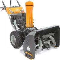
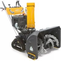
This machine is a snow thrower.
The machine is equipped with a clearance auger, protecting by a guard, that sends the snow to a discharge chute. The auger is moved by the engine that also drives the machine.
The machine is run using the controls located on the dashboard.
The operator can run the machine and activate all the main controls while staying upright in the operator's position, behind the machine.
3.1.1 Intended use
This machine has been designed and built to remove and clear away snow from pavements, gardens, drives and other ground-level surfaces. The snow thrower must only be used to remove snow.
3.1.2 Improper use
Any other usage not in keeping with the above-mentioned ones may be hazardous and harm persons and/or damage things. Examples of improper use may include, but are not limited to:
- use of the machine on surfaces above ground level, such as roofs on houses, garages, porticoes or other structures or buildings.
- Activate the auger in the presence of materials other than snow (e.g. soil, grass, pebbles, etc.),
- Pulling or pushing loads.
IMPORTANT Improper use of the machine will invalidate the warranty, relieve the Manufacturer from all liabilities, and the user will consequently be liable for all and any damage or injury to himself or others.
3.1.3 User types
This machine is intended for use by consumers, i.e. non-professional operators. The machine is intended for "DIY" use only.
IMPORTANT The machine must be used by one operator.
3.2 SAFETY SIGNS
The machine has various symbols on it (fig. 4). They are used to remind the operator of the behaviour to follow to use it with the necessary attention and caution. Meaning of symbols:

WARNING!
WARNING! Read the instructions before operating the machine.

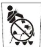
DANGER! Keep hands and feet away from rotating parts.

DANGER! Ejected objects. Do not turn the discharge chute towards onlookers or animals.

DANGER! Rotor turning. Always keep away from the snow discharge opening.

DANGER! Keep people, children and animals away from the work area.

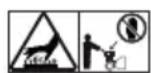
WARNING! Disconnect the key and read the instructions before carrying out any maintenance or repair work.
DANGER! Never put your hands inside the discharge chute when the auger is in motion. Stop the engine before unclogging the discharge chute.
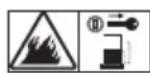
DANGER! Keep away from hot surfaces.
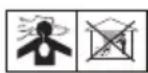
DANGER! Engines emit toxic carbon monoxide fumes. NEVER start the engine indoors.
DANGER! The fuel is flammable and explosive. Remove the key from the ignition and allow the engine to cool down before refuelling.

DANGER! Risk of fire or explosion. Do not smoke, do not use open flames or ignition.

DANGER! Always use hearing protectors.

DANGER! Wear eye protections.
IMPORTANT Any damaged or illegible decals must be replaced. Order replacement decals from an authorised assistance centre.
3.3 IDENTIFICATION LABEL
The identification label holds the following data (fig. 1):
- Manufacturer's address
- Type of machine
- Sound power level
- Conformity marking
- Engine operating revolutions
- Engine power
- Engine displacement
- Month / Year of manufacture
- Serial number
- Article code
Write the identification data of the machine in the specific space on the label on the back of the cover page.
IMPORTANT Use the identification names on the identification label of the product.
IMPORTANT Use these means of identification whenever you contact an authorized service workshop.
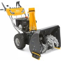
3.4 MAIN COMPONENTS
The machine is made up of the following main components (fig. 1):
A. Chassis
B. Dashboard
C. Engine
D. Fuel tank
E. Electric starter plug (Optional)
F. Handle for manual start
G. Deflector
H. Exhaust chute
I. Paddle
J. Auger safety guard
K. Auger
L Levelling skids
M. Lights (optional)
N.Wheel
4. ASSEMBLY
For storage and transport purposes, some components of the machine are not installed
in the factory and have to be assembled after unpacking. Follow the instructions below.
Unpacking and completing the assembly should be done on a flat and stable surface, with enough space for machine handling and its packaging, always making use of suitable equipment. Do not use the machine until all the indications provided in the "ASSEMBLY" section have been carried out.
IMPORTANT The machine is supplied without engine oil or fuel.
4.1 ASSEMBLY COMPONENTS
The packaging holds the components needed for assembly (fig. 3) listed in the following table:
| Pos. | Description | Q.ty |
| A | Gear control | 1 |
| B | Gear control fasteners | - |
| C | Screws and nuts for securing the handle in place | 4 |
| D | Gear and deflector adjustment lever grip | 2 |
| E | Discharge chute adjustment cable | 1 |
| F | Funnel | 1 |
| G | Safety key | 1 |
| H | Exhaust chute | 1 |
| K | Discharge chute sliding ring | 10 |
| L | M8 x 20 screws and spring washers | 6 |
| M | Chute skids | 3 |
4.1.1 Unpacking
- Cautiously open the packaging, paying attention not to lose components.
- Consult the documentation in the box, including these instructions.
- Remove all the unassembled parts from the box.
- Remove the snow thrower from the box.
- Dispose of the box and packaging in compliance with local regulations.
4.2 FORWARD AND AUGER CONTROL CABLE ASSEMBLY
Couple the cable eyelet to the specific opening (fig. 5).
NOTE The cables are already pre-assembled on the dashboard.
4.3 HANDLE ASSEMBLY
The handle is delivered with the dashboard already assembled. The screws for installing the handle on the machine, the screws for securing the gear control and the fasteners for attaching the discharge chute and the gear lever and deflector lever grips are all delivered in a separate package inside the box with the machine. Install as follows:
- Bring the two tubes at the ends of the handle (fig. 6.A) up to the support (fig. 6.B).
- Insert the screws in the holes and secure in place with the nuts.
4.3.1 Installation of the lever grips
Screw the grips onto the threaded rod of the gear lever (fig. 7.A) and the threaded rod of the deflector adjustment lever (fig. 7.B) accordingly. Tighten the fixing nut.
4.4 INSTALLATION OF THE GEAR CONTROL
- Insert the articulated joint (fig. 8.A) of the gear control in the hole on the lever (fig. 8.B) to connect it to the transmission and secure in place with the nut (fig. 8.C).
- Bring the top part (fig. 8.D) of the gear control up to the hole on the bottom part of the gear lever and secure in place by inserting the peg (fig. 8.E) and the cotter pin (already on the gear lever) (fig. 8.F).
4.5 DISCHARGE CHUTE ASSEMBLY
- Position the sliding ring (fig. 9.A) and the discharge chute (fig. 9.B) on the flange fitting (fig. 9.C).
- Insert the skids (fig. 9.D) under the flange fitting (fig. 9.C) by matching up the holes on the skid with the holes at the bottom of the chute.
- Insert the screws with the washers (fig. 9.E) in the holes and fasten.
4.5.1 Installation of the discharge chute adjustment cable
The adjustment cable is designed to connect the discharge chute to the adjustment handle on the dashboard so that the operator can point the discharge chute in the required direction.
- Secure the worm screw unit onto the support, checking the correct engagement of the worm
screw unit with the toothed section on the discharge chute (fig. 9.F).
- Engage the square section of the flexible cable in its seat at the bottom part of the handle (if not already pre-assembled).
- Tighten the cable ring nut (fig. 10.B) on the top part of the handle (fig. 10.A) (if not already pre-assembled).
4.5.2 Assembly of the deflector adjustment cable
The deflector adjustment cable is designed to connect the discharge chute deflector to the control on the dashboard so that the operator can lift/lower the deflector so that it is pointing in the required direction.
- Insert the peg (fig. 11.B) on the end part of the activation lever.
- Insert the end of the adjustment wire (fig. 11.C) on the peg (fig. 11.B).
- Insert the cotter pin on the peg and secure in place (fig. 11.D).
- Insert the adjustment screw (fig. 11.A) on the housing (fig. 11.E) and tighten the nut (fig. 11.A).
5. CONTROLS
5.1 IGNITION KEY
Used to start and stop the engine. The ignition key has two positions (fig. 13.A):
- Key removed - OFF - the engine stops and cannot be restarted.
- Key inserted - ON - the engine can start and run.
IMPORTANT The engine cannot be started unless the safety key is fully inserted. On some models you also need to turn the key clockwise to start it.
5.2 FUEL COCK
The fuel cock is opened to supply fuel (fig. 13.B).
- anti-clockwise - open.
- clockwise - closed.
5.3 THROTTLE CONTROL
Regulates the engine's r.p.m.
The positions, indicated on the plate, correspond to (fig. 13.C):

- Full throttle. Must always be used to start the machine and during operation.

- Minimum: used when the machine is sufficiently warm during stationary periods of operation.

- Stop position (if present). The machine stops immediately.

- Intermediate position (if present). Move the throttle lever towards the hare/tortoise to increase/reduce the speed and select the most suitable speed for the operating conditions (deep snow, uneven ground, etc.).
5.4 CHOKE CONTROL
Used to turn on the engine when cold. The choke control has two positions (fig. 13.D):

On the right - the choke is engaged (to cold start)

On the left - the choke is not engaged (normal warm start)
5.5 PRIMER
Press the primer bulb to inject fuel into the carburettor intake manifold to facilitate start-up when the engine is cold (fig. 13.L).
5.6 HANDLE FOR MANUAL START
Enables manual starting of the engine (fig. 13.H).
5.7 ELECTRIC STARTER CONTROL (OPTIONAL)
Enables electric starting of the engine (fig. 14.M) when the machine is connected to the electric mains using the specific plug (fig. 13.G).
5.8 FORWARD CONTROL
Enables forward movement of the machine.
- Lower the control (fig. 12.D) until it reaches the handle to advance.
- Release the control to stop the machine's forward motion.
If the forward control is activated with the auger control, it remains inserted on release. It disengages only when the auger control is also released (fig. 12.C).
5.9 AUGER CONTROL
Activates auger rotation.
To activate auger rotation, lower the control (fig. 12.C) until it meets the handle.
- If the auger control is activated by itself, upon release the auger stops rotating and the lever automatically returns to its original position.
5.10 GEAR STICK
The machine is equipped with gears activated using a stick (fig. 12.A):
- 5 gears for adjusting forward speed
2 gears for adjusting reverse speed
5.11 POSITIONING OF CHUTE AND DEFLECTOR
Rotation of the discharge chute is adjusted using the knob so that snow discharge can be aimed in the required direction.
- Turn the knob (fig. 12.E) clockwise/ anticlockwise to adjust the direction of the chute.
Deflector movement up and down is controlled by the specific lever (fig. 12.B). Move the lever forward/back to lower/lift the deflector.
- Lever fully forward = deflector lowered.
- Lever fully back = deflector high
5.12 HEADLAMPS SWITCH (OPTIONAL)
To turn the headlamps on, push the switch (fig. 12.F) forward.
- Headlamps on = red indicator light on
6. USING THE MACHINE
The safety regulations to follow during machine use are described in chap. 2. Strictly comply with these instructions to avoid serious risks or hazards.
6.1 PREPARATION
Before using the machine check for fuel and the oil level. For refuelling and oil top-up methods and precautionsent (seepar. 7.2 and par. 7.3).
Skids are used for adjusting the distance of the auger from the ground to safeguard it.
Before using the machine, adjust the skids as follows:
- Slacken the screws (fig. 14.A).
- Lift/ lower the skids (fig. 14.B)
- Tighten the screws.
6.2 SAFETY CHECKS
Ensure you have understood the contents before proceeding. Run the following safety checks and check the results correspond to those outlined in the tables.
Always carry out the safety checks before use.
6.2.1 General check
| Object Result | |
| Fuel lines and connections. | No leaks. |
| Electrical cables. All insulation | on intact. No mechanical damage. |
| Oil lines No leaks. | No damage. |
| Test driving No abnormal vibrations. No abnormal sound. | |
6.2.2 Traction and auger operation testing
| Action Result | |
| Start the machine (par. 6.3) | The wheels and auger must stay still. |
| Traction operation test | |
| Press the forward control (fig. 12.D). | The wheels should move the snow thrower forward. |
| Release the forward control (fig. 12.D) | The wheels stop. |
| Auger operation test | |
| Press the auger control (fig. 12.C) | The auger starts to rotate. |
| Release the auger control. | The auger stops. |
| Auger and wheel operation test | |
| Keeping the auger control pressed (fig. 12.C), press the forward control (fig. 12.D). | The auger should rotate and the wheels move the snow thrower forward. |
| Release the forward control (fig. 12.D). | The wheels rotate and the auger continues to rotate. |
| Release the auger control (fig. 12.C). | The auger stops and the wheels lock. |
If any of the results fails to match the indications provided in the following table, do not use the machine! Take it to a service centre to be checked and repaired if necessary.
- Open the fuel tap (fig. 13.B).
- Insert the safety key and turn clockwise, where indicated (fig. 13.A).
6.3.1 Cold start
- Turn the throttle to full on (fig. 13.C).
- Engage the choke (fig. 13.D).
- Press the primer bulb (fig. 13.L) twice or three times. Make sure that the hole is covered by your finger when pressing the bulb.
- Start, using the electric control (par. 6.3.5) or manual control (par. 6.3.3).
- Disconnect the choke (fig. 13.D).
IMPORTANT Before starting work with the machine, wait a few minutes for the oil to warm up
Warm start
- Turn the throttle to full on (fig. 13.C)
- Check the choke is disconnected (fig. 13.D).
- Start the machine electrically or manually (see below).
IMPORTANT During the warm start, do not press the primer bulb.
6.3.2 Manual start-up
To manually start the engine, slowly pull the handle (fig. 13.H) outwards until resistance is felt. Then pull sharply and accompany the handle as you release it. Repeat the operation until the engine starts.
NOTE Do not make more than 3/4 attempts, otherwise you risk flooding the engine. Check the possible causes for a non-start in the "Problems identification table".
6.3.3 Electric start-up
Make sure that the electricity supply is duly earthed and fitted with an automatic circuit breaker.
- Insert the plug (fig. 13G) into a 230V power supply socket.
- Press the start button to start the engine.
- Once the engine is running, remove the plug from the socket.
6.3.4 Operation
To operate with the machine proceed as described below:
- Using the specific control, position the chute and the deflector (fig. 1.G).
To increase the length of the snow jet, position the deflector upwards. - To decrease the length of the snow jet, position the deflector downwards.
- Set the gear depending on the route and the depth of snow.
- Press the auger control (fig. 12.C) to activate auger rotation.
- Press the forward control (fig. 12.D) to activate traction.
NOTE Always use full throttle when using the machine.
6.3.5 Steering
Steering helps drive the machine in the desired direction.
Steering is facilitated on models with the "diff-lock release" (see technical data table).
6.3.6 Gear change
Gears are changed with the machine stopped.
To change gear, proceed as follows:
- Stop the machine by releasing the forward control (fig. 12.D) and the auger control (fig. 12.C).
- Move the gear stick to the desired position (fig. 12.A).
- Start operating as normal again.
IMPORTANT Changing gears with the machine moving causes damage to the gearbox.
6.4 STOPPING
To stop the machine, release the auger control (fig. 12.C) and the forward control (fig. 12.D).
To turn off the machine, proceed in one of the ways described:
- Remove and turn the safety key (fig. 13.A).
- Move the throttle (fig. 13.C) to the stop position.
The fuel cock must always be closed when the machine is not in use.
The engine may be very warm immediately after it is shut off. Do not touch the exhaust or adjacent parts. This can cause burn injuries.
IMPORTANT If you need to leave the machine unattended, always remove the safety key (fig. 13.A).
- Snow is removed more easily when it is still fresh. Pass back over the already cleared zones to remove snow residue.
- If possible, clear the snow in the direction of the wind. Check the distance and the direction of the removed snow jet.
- In strong winds, lower the deflector to direct the discharged snow towards the ground, reducing the likelihood of the wind transporting the snow to the wrong areas.
- Once you have finished work, leave the machine running for a few minutes to prevent ice from forming in the discharge chute.
- Always maintain a suitable speed for the snow conditions, adjusting it so the snow is removed in a constant flow.
- Reduce the engine rotations before stopping it.
6.6 AFTER OPERATION
Clean (par. 7.4).
- Move all the controls forward and back a few times.
- Check the choke is engaged.
- Check there are no loose or damaged components. If necessary, replace the damaged components and tighten any screws and loose bolts.
Do not cover the machine when the engine and the exhaust are still warm.
7. MAINTENANCE
7.1 GENERAL INFORMATION
IMPORTANT The safety regulations to follow during machine use are described in par. 2.4.
All service and all maintenance checks must be carried out on a stationary machine with the engine switched off. Before cleaning or doing maintenance work, take out the ignition key and read the relevant instructions.
Wear adequate clothing, gloves and goggles before carrying out any maintenance.
- The frequency and types of maintenance are summarised in the "Maintenance Table". The table will help you maintain your machine's safety and performance. It summarises the main interventions to be made and the frequency applicable to each of them. Carry out the relevant intervention according to the first deadline.
- The use of non-genuine spare parts and accessories could adversely affect machine operation and safety. The manufacturer shall decline all liability in the event of injuries or damages caused by such parts.
- Genuine spare parts are supplied by authorized assistance workshops and dealers.
IMPORTANT All the maintenance and adjustment operations not described herein must be carried out by your dealer or Authorised Service Centre.
7.2 REFUELLING
To refuel:
- Unscrew the tank closure cap and remove it (fig. 13.E).
- Insert the funnel (fig. 13.l).
- Refuel and remove the funnel (fig. 13.l).
- Close the fuel cap securely after refuelling and clean away any spills (fig. 13.E).
NOTE Do not fill the fuel tank right to the top.
NOTE Only use the fuel indicated in the data table. Do not use other types of fuel. It is possible to use ecological fuels, i.e. alkylate petrol. The composition of this petrol is less harmful to people and the environment. No negative effects linked to use of the same have been reported. However, there are types of alkylate-based petrol available on the market for which it is not possible to give
precise indications regarding their use. For further information it is advisable to consult the instructions and data provided by the producer of the alkylate-based petrol.
NOTE Fuel is perishable and should not remain in the tank for more than 30 days. Before storing for a long period, fill the tank with a sufficient amount of fuel to reach final destination (chap. 8).
7.3 CHECK/TOP-UP ENGINE OIL
Always check the oil level before use.
NOTE The machine is delivered to the client without engine oil.
7.3.1 Check/top-up
Procedure:
- Position the machine on a level surface for the check.
- Clean around the plug (fig. 13.K). Unscrew and remove it. Clean the rod.
- Push the dipstick down completely without screwing it into place.
- Now pull the dipstick up again. Read off the oil level.
- Top up if the level is lower than the "L" mark (fig.15)
- For the correct replacement procedure, see par. 7.3.2
Do not overfill as this could cause the engine to overheat. If the oil level exceeds the "H" mark (fig.15), the oil must be drained until the correct level is achieved.
NOTE For the type of oil to use, see the "Technical Data Table".
7.3.2 Replacement
The oil may be very hot if removed just after the engine has been switched off. Consequently allow the engine to cool down for a few minutes before proceeding to drain off the oil.
Replace the engine oil based on the frequency indicated in the "Maintenance Table". Change the oil more frequently if the engine has to operate in demanding conditions.
Proceed as follows:
- Place the machine on a flat surface.
- Place a suitable container under the drain plug.
-
Remove the top-up cap (fig. 13.K)
-
Remove the drain cap (fig. 13.J)
- Collect the oil in a suitable vessel.
- Screw the oil drain plug back in.
- Clean up any spills.
- Fill with fresh oil. For the quantity of oil to use, see the "Technical Data Table".
- After filling up the oil, start the engine and leave it to idle for 30 seconds.
- Check there are no oil leaks.
- Stop the engine. Wait 30 seconds and check the oil level again. If necessary, also see "check/top-up" (par. 7.3.1).
IMPORTANT Hand the spent oil over to a disposal facility in accordance with local provisions.
7.4 CLEANING
Carry out cleaning operations with the machine switched off. Do not try to remove snow from the discharge without firstly:
- Releasing the auger control.
- Turning off the engine.
- Removing the ignition key.
Always clean the machine after use. To clean the machine adhere to the instructions provided below:
- Use the shovel (fig. 1.l) to clean the discharge chute and for cleaning accumulated snow off the machine.
- Clean the engine with a brush and/or compressed air.
- Do not spray water directly onto the engine.
After cleaning using water, start the machine and auger to remove any water which may otherwise end up in the bearings and cause damage.
IMPORTANT Never use high-pressure water jets. It could damage the electrical components.
7.5 SPARK PLUG
For spark plug operations, contact the Dealer or Authorised Assistance Centre. Consult the Maintenance Table and the Problems Identification Table for any intervention on the spark plug.
7.6 CARBURETTOR
The carburettor is pre-tuned by the manufacturer. Consult the Problems Identification Table to check when intervention is required on the carburettor (chap. 12).
7.7 NUTS AND BOLTS
- Keep all nuts, bolts and screws tight to be sure the equipment is in safe working condition.
- At frequent intervals check all fasteners on the discharge chute to ensure they are securely tightened.
7.8 THE AUGER SHAFT
To facilitate the rotation of the auger, it is recommended to periodically grease nipples (fig. 16.A) of the auger shaft using a grease gun. To grease:
- Remove the cotter pins and the safety pegs (fig. 16.B).
- Grease the nipples (fig. 16.A) and turn the auger on the shaft several times to allow the grease to flow inside the shaft.
- Replace the safety pegs and the cotter pins. (fig. 16.B)
8. STORAGE
When you intend to put your machine away for more than 30 days:
- Empty the fuel supply circuit:
- Close the fuel tap (fig. 13.B).
- Start the machine's engine and leave it running until it runs out of fuel.
- Change the engine oil if this operation has not been done in the last three months.
- Clean the snow thrower thoroughly.
- Check for any damage. If necessary, see to the necessary repairs.
- If the paintwork is damaged, touch it up to prevent rust.
- Protect any exposed metal surfaces from rust.
- Store the snow thrower indoors if possible
9. ASSISTANCE AND REPAIRS
This manual provides all the necessary information to run the machine and for correct basic maintenance operations which can be performed by the user. Any regulations and maintenance operations not described herein must be carried out by your Dealer or Authorized Service Centre, which have the necessary knowledge and equipment to ensure that the work is carried out correctly, maintaining the correct degree of safety and the original operating conditions of the machine.
Any operations performed in unauthorized centres or by unqualified persons will totally invalidate the
Warranty and all obligations and responsibilities of the Manufacturer.
Only authorized service workshops can carry out guaranteed repairs and maintenance.
- The authorized service workshops only use genuine spare parts. Genuine spare parts and accessories have been designed specifically for machines.
- Non-genuine spare parts and accessories are not approved. Use of non-genuine spare parts and accessories cause the warranty to expire.
- It is advisable to send your machine once a year to an authorized service workshop for servicing, assistance and safety device inspection.
10. WARRANTY COVERAGE
The warranty covers all material and manufacturing defects. The user must follow all the instructions provided in the accompanying documentation.
The warranty does not cover damages caused by:
- Failure to become familiar with the documentation accompanying the machine.
- Carelessness.
- Incorrect or prohibited use or assembly.
- Use of non-genuine spare parts.
- Use of accessories not supplied or approved by the manufacturer.
The warranty does not cover:
- Normal wear and tear of consumables, such as drive belts, drills, headlights, wheels, bolts and wires.
Normal wear and tear. - Engines. Engines are covered by the warranty provided by the relative manufacturer in compliance with the specified terms and conditions.
The purchaser is protected by his own national legislation. The purchaser's rights envisaged by the national laws in his own country are not in any way restricted by this warranty.
11. MAINTENANCE TABLE
| Intervention Frequency | Paragraph | ||
| First time | An then after | ||
| MACHINE | |||
| Check all fasteners | - | Before each use | 7.7 |
| Safety checks/check controls | - | Before each use | 6.2 |
| General cleaning and inspection | - | Cleaning the exhaust area | 7.4 |
| Cleaning the discharge area | - | 5 hours / after each use | 7.4 |
| Lubrication of the drive shaft. | - | 25 hours / every season | *** |
| Lubrication of the auger shaft. | - | 10 hours / every season | 7.8 |
| ENGINE | |||
| Cleaning the spark plug | - | 25 hours / every season | *** |
| Replace the spark plug | - | 100 hours / every season | *** |
| Check/top up engine oil | - | 5 hours / after each use | 7.3.1 |
| Replacement of the engine oil | 5 hours | 50 hours / every season | 7.3.2 |
*** Interventions which must be carried out by your dealer or an authorised assistance centre
12. PROBLEM IDENTIFICATION
| PROBLEM PROB | ABLE CAUSE REMEDY | |
| 1. No start | Ignition key not inserted. Insert the ignition key. | |
| No fuel. Fill the tank with quality, pure fuel. | ||
| Choke disconnected Engage the choke. | ||
| Primer bulb not pressed Press the primer bulb | ||
| Engine flooded Wait a few minutes before starting. Do not press the primer bulb and disconnect the choke. | ||
| Spark plug damaged Contact the authorised assistance centre. | ||
| Spent fuel Contact the authorised assistance centre. | ||
| Water in fuel Contact the authorised assistance centre. | ||
| 2. Power loss. | Too much snow thrown Reduce speed | |
| Fuel tank cap covered with ice or snow. | Remove ice or snow from over and around the tank cap | |
| 3. Engine rotates at the minimum or operates irregularly | The choke is engaged | Disconnect the choke. |
| Spent fuel Contact the authorised assistance centre. | ||
| Water in fuel Contact the authorised assistance centre. | ||
| Carburettor needs replacing | Contact the authorised assistance centre. | |
| 4. Excessive vibrations | Loose parts or auger or rotor damaged. | Tighten all the fastening devices. Replace the damaged parts in the authorised assistance centre. |
| Handle not correctly positioned. | Ensure the handle is fastened in its position. | |
| 5. Loss or slowing of thrown snow | Blocked discharge chute. | Clean the discharge chute. |
| Auger blocked. | Remove any dirt or foreign bodies from the auger. | |
| 6. Traction not working. | Traction drive command cable not correctly adjusted. | Contact the authorised assistance centre. |
If problems persist after having performed the above operations, contact your dealer.
INDICE
7.8 EJE DE LA COCLEA
11.HOOLDUSTOODE TABEL 12
- RIKETETUVASTAMINE 13
1. ÜLDANDMED
1.1 KUIDAS KASUTUSJUHENDIT LUGEDA
5.6 POIGNEE DE DEMARRAGE MANUEL
2.3 BO TEKOT HA PABOTATA
06nact3a pa6ota
He KopncTeTe ja MaunHaTa BO cpeHnHa Kaede nocToN p3nK OJ eKcnlo3nJa, BO npCycTBo Ha 3aapanBn MaTepn, racobn nn HeuNcTOnJa. EJeKtpnHnTe KOHTaKTn nn MExaHnKnTe DeJIOBn MOKe Da reHepnpaaT NCKpn KOn MOKe da Tn 3anaat npabOT nn HcnapyBaHaTa.
He naIeTe ro MOTOpOT BO 3aTbOpeH npocTo pKe MoKe Da ce cObepaT onacn jaIePoj MOHcNdHr racOBn. OnerpaunTe 3a nane He Tpe6a Da ce H3BeDaT Ha OTBopeHo HIn BO npocTo KoJTo Do6Po Ce npoBeTpBya. 3aONmHeTe DeKa N3dyBHnTe rAcOBn Ce OTPOBn.
Pa6oTe cAmo Ha DHeBHa CBeTInHa nn npn Do6po BeWtAChO OCBeTJeHne n npn ycNoBn Ha Do6pa BnDnBOcT.
- OndaJeTe rN IucaTa, Deuata N HINBOTHTe OD o6laCTa 3a pa6ota.
HeonxoJHO e deuata da 6nT noHa3Op Ha npyro BozpaHo Iue.
- O6pHeTe oc6eHbBnMaHne Kora ja KOpNCTIte MaunHaTa Ha NaTeHb BO rpaHnHaT, TpoToapn Hb yInu nn Kora r npemHyBaTe. BnMaBajTe Ha cokpneHTE onaCHOCTn.
BHHMabajte Ha coo6paKajot Kora MaunHaTa ce KopncTn BO 6JIn3nHa Ha nAT.
OndecyBaHe
He hacouybajTe ro OTBOPOT 3a nCnycTOT Hacnpotn BeTpOT NIN KOH Lyre, KHBOTHN, BO3Nla, DOMOBN IN KOH CE dpyro wTO MOKe Da ce OWTeTc CO CHEROT. He Do3BOJyBaJTe HNKoJ Da CTOn IpeMaunHaTa.
Hnkoraaw He KopncTeTe ro uNCTaOT 3a CHER BO 6n3Ha Ha OpaDN, aBTOMO6nHN, npo3OpN, nlouHNu cNHyHO 6e3 Da rO perylnpate COoDBeTHO DeΦJIeKTopoT Ha JeIOT CO NcnyCTOT.
He np6bnKybaJte rH Ho3eTe npaTe do potnpaunTe deIOBn. DpKeTe ce nOdaIeKy od OTbOpOT Ha DeIOT 3a nCphiJaBe Ha cHEROT. OdpKyuBaJte ro OTbOpOT 3a nCphiJaBe CeKOraU qNCT.
Ako uctaOT 3a CHER NcPpIIN CTpaHn TeJa nn npojabyBa HeHOpMaJIHN Bn6paun, n3racTe rO MOTOPOT, n3BaJeTe rO KJIyOT, noyeKaJTe Da CE CMnpaT DeIOBnTe wTO ce DnKHaT N TeMeIHO npOBepeTe ja MaunHaTa 3a Da yTBpDnTe DeKa Hema OwTeTyBaHa. HopMaJIHo, Bn6paunTe ce CmNTOM 3a npCycTBo Ha npo6JeM. POnpaBeTe rN MOxHnTe DeΦeKTH nped Da ja yNoTpe6nTe MaunHaTa.
- PpeIa ce OdaJeHTe OD MaunHaTa, NCHnyte Tn CNTe KOMaHn IN 3BaTe To KlyOT 3a NaJeHb e OD JeHNsTeTo Ha MaunHaTa.
- Ppei Da pa6oHTe Ha nonpaBkn, YnCTeHbe, npOBepKa n perylauJa, n3raceTe rO MOTOPOT, n3BaTeTe rKnyOT n NOyeKaJTe Da ce CMHpAT DeIobNte wTO Ce DnHKaT (OCBeH aKO Hema dpyrN 3peuHn HacOKn BO yNaTCTBOTo). N3BaTeTe rKabInTe OD eJIeKTpUHHOT MOTOp. (No n36Op)
He donnpajte ng deJIOBHTe Ha MOTOPOT TO ce 3arpeBaat BO TEKOT Ha pa6oTata. Pn3nk od oneKOTHH.
He KopncTeTe ja MaunHaTa co roJema 6p3Ha ha DnKeHBe Ha IIN3rABn Tepen. O6pHeTe BnMaHne Kora Onde Hana3aI. NOrJeHete 3a Hea PpeN IN pN DnKeHBe Hana3aI 3a da Obe36eDInTe DeKa Hema HnKaBn PpeKn.
IcHnyeTe ro ceYnBOTO Kora ja TpaHCnOpTnpaTe MaunHaTa nn Kora He ja KopNCHTte.
- Cekoraun npOBepyBajTe daNn do6pn ycNoBn 3a paMHOTeKa n cBpCTo dpKeTe ja paKaTata. OdeTe, He TprJaTe.
OrpaHcyBaHe npn ynoTpe6a
He KopncTeJe maunHaTa nonpeky Ha 3aKocen Tepen. CeKoraU DBnKeTe ce Orope HADOLy, a nOToa OdoJy HaRope. O6pHETe BnMaHne Kora To MeHyBaTe npabeQT Ha 3aKocen Tepen. N36erHyBajTe rOJIem CTeEN Ha 3aKocEHn TepEN.
He KopncTeTe ja MaunHaTa aKO 3aHTnTaTa He e 3aIOBOJIteJHa n aKO 6e36eHOCHTe ypeN He ce npabnilho noCTaBeHN.
He ncknyuBajTe rMaHOMeTapOT 6e36eHNCHNTe CnCTEmN.
He meHyBaJTe rnpereylaunite Ha MToPOT H He DoBeDyBaJTe FO MOTOPOT BO RoIem peKnM Ha pa6ota.AKO MOTOPOT NoHc da pa6oTn CO npekymepen 6pOJ Ha BpTeHN, Pn3NKOT OJ LInHn NOBpeDi Ce 3rOJIeMyBa.
He nperepeBajTe ja MaunHaTa ynpaByBajKn ja co roJema 6p3nHa.
He ctabajTe rpaete Bo OTbOpOT nIN BO deIOT 3a HcphiJaBe 6e3 npetXoJHO da ro nCHnyHTe MOTOPT n Da rO n3BaAnTe KlyOT.
2.4 ODPKHYBAHbE,ODJIAGAHbE INTPAHCIOPT
PeOBHO OdpKyBajTe n npaBnHObIOJIOKeTe ja MaunHaTa 3a da ja ODPKHTe6e36eHocTa Ha MaunHaTa.
OwTeHHe Hn DeΦeHTHe JelOBn Tpe6a da ce 3ameHaT, HnKoraw Da He Ce nonpabaat. HopncTe cAmo opnHnHaHn pe3epBHN DeIOBn: ynotpe6ata Ha DeIOBn KOntTo He ce opnrHnAHHn Hn HecooDBetHO NoCTaBeHN MoHe da DOBeda Tdo HHndENTn Hn NnHn NOBpeH, a CO Toa ce OcNo6OyBa Ipon3BODHTeNtO od Cekoja O6Bpcha nHn ODROBOPHOCT.
OdpHyBaHe
Ako pe3epboapoT tpe6a da ce ncpa3HN, nCTOTO Tpe6a da ce npabn Ha OTbopeHo N KOra MOTOPOT e 3naDeH.
3a da ro HamaJIte pN3HOT od noJap, peoBHO npOBepyBaJTe daJIIMa npOleaHO MacIIO N/INI rOpINBO.
Ondarabe
He octabajTe ropno BO pe3epboapot ako ja Ondarate MaunHaTa BO npocToP KaDe nCnapyBaHbTa OD rOpNBOTo MoKe Da CTanat BO KOHTaKT CO OTBOpEH OrAH, NCKPN IN3BOpn Ha TOnnHa.
- Octabete ro MOTOPOT da ce n3laHnpei da ro odIOJNte YnCTaOT Ha CHER BO 3aTBopeH npocToP.
- CekoraawocbpheTeCeHa ynaTCTBaTa3a ynoTpe6a 3a BaKHNte DeTaNnako YnCTaOT Ha ChER Tpe6a Da Ce KOH3epBnpa Ha NoDolr NepNOd.
TpaHcnpT
Ako MaunHaTa Tpe6a Da ce TpaHcnpTnpa Ha KaMOn Hnn BO npKoJka, yNoTpe6eTe npueKn 3a OTnop, no DoJHKnHa n WnpHa.
Hocete ja MaunHaTa CO n3raChaT MOTOP 6e3 MOxHOCT da Ce BkIyU, anraHnajKn COoDBetEn 6poj Niua.
Bo TeKOT Ha TpaHCnOpTOT, 3aTBopeTe ro DOBOoT 3a 6eH3nH (aKO e npedBnIeH) n Obe36eTe ja COOdBETHO MaunHaTa BO TeKOT Ha TpaHCnOpTOT co JaKNbA u CnHnIpN.
2.5 3AUHTITA HA HKNBOTHATA CPEINHA
3aHTTaHa JnBToHaTa CpeHnTaPe6a Da ce n3BpyBa peIeBaHTHO npOpTeTHO pni yNtpe6a Ha MaunHaTa BO KOpCT Ha rpaHcHNTe NOroHocTn HA IpocTopOT Bo KoJ KInBeeme.
- N36erHyBajTe nojaba Ha eIemEnTH uTo rO HapyuBaat HenocpeHOTo ONkpyKyBaHe.
- DocneHcJeTe rI JOKaHHTe 3aKOHn 3a φpnahe Ha ambaJhaTa, MaclaTa, rOpNBOTo, aKymJaTOpOT, fNITPnte, DeIOBn BO paCnaraHe NII KAKBn 6bNo eIemEnTH CO WTeTHO BInjaHne BP3 HINBOTHaTcpeDnHa. OBne OTnadoOn He cMee Da ce φpnaat Bo rγ6pe TyktypeBa Da ce CeIeKTnpaat n OdHeCat BO COODBeTHn CO6nPHn CEHTpn KO npueKNlnpaaT MaTePiJaHn.
-ПиИСФРа№ОуNotpe6a,HeOCTaBajTe jaMaшинаТаКадeБиLOВОприрогдатуКупразAJTe ja BOcoбиpenцentapBO corlaachocSTCoBaЖeЧКteJOKaJIH3aKOHN.
3. 3ANO3HAJTE JA MAUNHATA
3.1 ONHC HA MAUHHATA IN PPEBUNDEHA YNOTPEBA
ObaMaHHa e Ynctau Ha Cher.
MaunHaTa ce doCTaByBa co CEuHb 3a
pacnctybahe cher, 3aTnteH co KapTeP
Ito Ho HacOuyBa CHEROT KOH OTBOPOT 3a
ncpplae. MoTOPO T O DBNHN CeuHBOTo
KoJTo ja npDnKyBa n MaunHaTa.
YnpabvBaBeTo co MaunHaTa ce npabn Co
KOMaHdnte NoCTaBeHn Ha KOHTpOHaTa Ta6la.
OnepaTopoTe BO N03njuJa Da ynpaByBa CO MaunHaTa N Da Tn BknyBa TnaBnTe KOMaHdN Co HO3e, BO N03njuJa Ha ynpaByBaHBe, OZ3aDn Ha MaunHaTa.
3.1.1 IpeBnEHa ynoTe6a
Obaa MaunHa e npoeKtnpaHa n KOHCTpynpaHa 3a YnCTeHe, pacnctyBaHe n NcPpnaHe Ha CHEROT OD TpoToapn, rpaHH, NaTEKN dpyr paMHN NOBpHH. YnCTaOT Ha CHER Tpe6a da ce KOpNCtnc Camo 3a OTCTpaHyBaHe Ha CHEROT.
3.1.2 HecooBetheHa ynotpe6a
Koja n da e npya ynoTpe6a,nonHaBb oJ
ropeHabeDeHTE,MOHe Da npetCTabyBa
onachOCT n da npeIN3BnKa NOBpeN uWTeTN
3a Iuca n/nnn PpeMeTu. Ce otpplaaT
Pn HnnpaBnHa ynoTpe6a (kaHO npImep,
Ho He ce orpaHcyBa Ha cneHOTO):
- KopncTeTe ja MaunHaTa Ha NOBpuHHn Ha3emjata, KaKo wTo ce KpoBOuHa 3rpaHn, rapaHn, Tepacn n dpyr n rpaDbn 3rpaHn.
Bknyute Tn HOKeBnTe 3a OToPpnaHe Kora Hema CHer (Ha 3emJa, TpeBa, KepamuN n cI). - Повлесуеши заразугни Kapисе.
BAHHO HecooDbetHaTa ynoTpe6a Ha MaunHaTa IOBeyBa DO OTpnaHe Ha rapaHnJaTa I ja OTpPa CeKoJa OndroBOpHoCT Ha npOn3BODHTeIoT, ppePpLyBajn rHa KOpncNtO pOn3Je3eHnTe Obpcn IppeDn3BnKaHn OJ NobpeDn Nn OwTeTyBaHaTa InuHO nI Ha TpeTn Nua.
3.1.3 BnHa KopncnK
Obaa MaunHa e HameHeTa Da ja KaOpNCTaT KopnCHnU, T.e. OepaTopu KOnuTo He ce npoPecnoHaJIu. HameHeTa e 3a ,DomaSHA yNoTpe6a".
BAHHO MaunHaTa MoKe da ce KopnCTn camo co OepaTOP.
3.2 O3HAKN 3A B6E3BEdHOCT
Ha MaunHata Nma Cm60Jn (cI.4). HnBnata 3aJa a e da ro notCeTyBaat OepaTopoT Ha NOCTaNKITE WTO Tpe6a Da rN CJIeDN BHNMaTeJHO I CO 3aOJHKTeJHm MepKn 3a npETNa3JINBOCT. 3NaueHe Ha Cm60Jnte:

BHIMAHNE!

BHIMAHHE! IpouNTajTe ro yNaTCTBOTO nped da ja KOpNCTITE MaunHaTa.
ONACHOCT!Држete Г paçeteи Ho3e Te nodaJIeKу OД рOTИРаЧКпTe DeJIOBn.

ONACHOCT! Ncφpnahe npedmetn. He hacoybajte ro OTBOPOT 3a Ncφpnahe KOH npncyTHnte HN KOH KHBOTHNE.

ONACHOCT! PoTnpaKn DeIOBn. Cekoraw cTojTe OdaJeHcHO od OTBOPOT 3a nCpPnaHe CHER.

ONACHOCT! Odpkybajte ja cpeinhaTa 3a pa60ta Yncta OD BO3paCHN Iua, Deua N KHBOTH.

BHIMAHNE! N3BaTe ro KnyOT n npOHTajTe ro yNaTCTBOTO nped Da n3BeDyBaTe KaHbN 6nlo DejCTBa 3a odPxyBaHe nnl nonpaBAka.

ONACHOCT! H36erHyBajTe Da rN CTaBaTe paueTe BO KaHaIOT 3a NcΦpIaHBe DOeHa ce DnKHaT HOKeBNTe 3a NcΦpIaHBe. 3actaHete ro MOTOPOT nped Da O nCKJyUHTe npNKJyOKOT oD HanojyBaHe.
ONACHOCT!Држete pactojaHne OTOJINTe NOBpHHN.
ONACHOCT! MoToPoT emnTyBa jaIepeoMOnokCnI. HE naIeTe ja MaHHaTa BO 3aTBopeH npocToP.
ONACHOCT! TOpNBOTo e 3aJaINBO n EKcIIO3nBHO. N3BaTe ro KlyOHOT 3a NaJIeHBe H OCTaBeTe ja MaunHaTa Da ce N3JaDn PpeD Da HaOnoJHInTe TOpNBO.

ONACHOCT! NocToN pU3nK od noJap nn EKcnpo3nJa. He nyweTe n He octabajTe OTBOpEN oran nn n3BOpn Ha naJeHe.

ONACHOCT! HocTe 3aHTnTa 3a yuN.

ONACHOCT! Hocete 3aHTNTH OYNJIA.
BAHHO Daenhte etnKetuTo ce cnHaJe NN He Ce YHTNHB, TpeBa da Ce 3aMeHaT. NobapajTe HOBu etnKeTu OJ COoDbETeH UENTAP NNN OD OBnactehNOt CepBncep.
3.3 ETHKETA 3A INDEHTNΦHACUNJA
ETnKeTaTa 3a nHeHTnΦnKaunja rN coDpHn cIeHNTe NoDaTOU (cI.1):
1.AdpecaHa npOn3BODntTeIOT
2. TnHa MaunHa
3. HNBO Ha aKcYCTnHa MOHOCT
4. O3HaKa 3a yCOrJaIaceHoCT co CE
5. Bpoj Ha BpTeHH Ha MOTopoT
6. MoKHoCT Ha MOTOPOT
7. KanaiuTeHa MoToPoT
8. Mece/ToDHa Ha npOn3BOdCTBO
9. Cepinckn 6proj
10. KoI Ha npOn3BOd
3aannweTe rnoTouHTe 3a
HNeHTnKauJa 3a MaunHaTa Ha
COoBbETHHe MeCTa Ha DaDeHata ETHKeTa
OD BHaTpeWHaTA CtpaHa Ha KaNaKOT.
BAHHO KopncTeTe rH MMnBaTa 3a NdeHTnΦnKaunja Ha daDeHaTa eTNKeTa 3a NdeHTnΦnKaunja Ha MaunHaTa.
BAHHO KopncTeTe rN NMHbata 3a ndeHTnphiKaunja cekojnat Kora KOHTaKTnpate CO OBnacteh ueHTap.
3.4 JIABHN DEJIOBN
MaunHata ce coCTOn Od CNeHNTe rnaBn DeIOBn (cI.1):
A. Pam
B. KoHTpoJIHa Ta6Ia
C. MoTOp
D. Pe3epBoaap 3a ropInBO
E. Ппклuyok 3a eelenKtpnHOn naJIeHe (No n36Op)
F. Paça Ka 3a paCyHo nαJIeHBe
G.ДeфЛeКТОр
H. OTBOP 3a nCΦpIaIbe
I. Jlonatka
J. KapTeP 3a 3auTtHa Ha ceuBTo 3a CHER
K. CeuBa
LПLOUa3aHNBeJIpaHe
M. CBeTna (no n360p)
N. Tpkano
4. MOHTHPAHBe
3a noTpe6nte Ha cKlaIpaIbe N TpaHCnOpT, OndepEn HOMnoHENTHa MaunHaTa He Ce MOHTnpaHbBO φabpnKaTa, TykY Tpe6a Da
ce MOHTnpaat no BaedeHe Ha am6aJaKaTa cIeJeKn rN CJIeHNTe yNaTCTBa.
PacnakybaheTo n ceJaTa MOHTaHa Tpe6a da ce n3BpwaT ha cBpcta n pamHa NOBpuHnHa CO DOBOJHo npocToP 3a NOMecTyBaHe Ha MaunHaTa N Ha ambaHata HOpNCtejHn Cekoraw COoDBeTHn aIaN. He KopNCteTe ja MaunHaTAppe Da 3aBpWnte CO CHTe NOCTaHHn HabeJeHN BO norlaBJeto ,MOHTHPAHe".
BAHHO MaunHaTa ce DocTaByBa 6e3 MacNo BO MOTOpOT n 6e3 rOpNBO.
4.1 DEJIOBn 3A MOHTHPaHbE
Bo ambaHata Hma n DeIOBn 3a MOHTnpaHe (cI.3) HabeHn Ha cJeHaTa Ta6eJa:
POnuHTe, NocOeHN Ha Ta6JnUkata, COoDBeTCTByBaat (cI. 13.C):

- Zeioceh peHm Ce Kopnctn ceKoraw 3a naJeBe Ha MOTOPOT Ha MaunHaTa N BO TEKOT Ha pa6oTaT a.

- MInHmym - ce KopncTn Kora MOTOpOT e 3aIpeah BO TEkOT Ha fa3nte Ha 3aIIpaHe.
STOP
3.ПоЗициJA3a3acTaHyBaHbe(aHOma).MaunHaTaaactaHyBa BeHaI.

- CpeHa no3nUJa (aKo nMa). Typkajn ja paKaTa Ha 3a6p3yBaYOT KOH cInKaTa CO 3ajaK / JKeIka Ce 3roJeMyBa / HAmAlyBa 6p3nHaTa N Ce n3bnpa COOdBETHaT3a NOTpe6nte Ha pa60TaTt (BcOK CHer, HepaMeH Tepen n CInuHO).
5.4 KOMAHDA3A INPNDUWBAHBe
Ce Kopncn Kora ce naHnaDeH motop.KomahdaTa 3a npnyuBaohm aDbE nozun (cI.13.D):

HaDecHO - npDnyuBaOte aKtNBpuH (3a TprHyBaHe Ha naHo).

Haedcno - npduyybaot e ncknyeH (HopmaHa pa6ota n TprHyBaHe co 3aqrpeah MOTop).
5.5 NOTTNHHYBAH
PnTnckajkn ja rymeHaTa KOMaHda Ha 3a6p3yBa4OT ce nHnCnpa Kap6ypaTOPoT BO KOJIeKTopoT 3a NOBLeKyBaHe Ha
TROPUBOTOCO WTO CE OJECHYBa NaJIeHbETo Ha CTyJeH MOTOP (cI.13.L).
5.6 PAUHA 3A PACHO NAJEHe
OBO3MOKHyBa paHNo napeHeHa MOTOpOT (cI. 13.H).
5.7 KOMAHДA 3A EJIeHTPNUH0 IaJIeHbE (IIO N3bOP)
OBO3MOxHyBa eIeKtpnHNo naJIeHe Ha MOTOPOT (cI. 14.M) Kora MaunHaTa e NOBp3aHa BO cTpyJa npEky DaDeHNO TpNkLyUOK (cI. 13.G).
5.8 KOMAHDA3AДВИХЕБE
OBO3MOKHyBa DBNKeHBe Ha MaUNHaTa.
- CnyuTeTe ja komaHaTa (cI. 12.D) 3a da MoKe da rN npHTnCHeTe paKoΦaTnTe 3a DnHeBe.
- NpWTeTe ja KOMaHdaTa 3a Da ro 3aCTaHete DnKHeBeto Ha MaunHaTa.
AkoKOMaHdaTa3aDbNKeHe ce aKTbBnpa 3aeDHO CO KOMaHdaTa 3a CeYNBOTO, OCTaHyBa aHTbBnpaHa. Ce de3aKTbBnpa camo Kora Ke ce OTnyuTNI KOMaHdaTa 3a CeYNBOTO (cI.12.C).
5.9 KOMAHDA3A CEYNBOTO
To aKTHBnpa BpTeHbEtO Ha ceYNBOTo 3a CHER.
CnyuTeTe ja komaHdaTa 3a da aKTbNpaTe BpTeHe Ha ceYnBOTO (cI.12.C) taKa wTo Ke moKe da ja npNTUCheTa paKaTa.
Ako ja aKTbHpaTe cAmo KOMaHaTa 3a ceHBOTO, Kora Ke ja OTnyHTT, BpTeHeTo Ha CeHBOTO 3aTaHyBa n paKaTa ce BpaKa aBTOMaTcN BO npBnHaTa NOJok6a.
5.10 PAUHA HA MEHYBAQOT
MaunHaTa Ce DocTaByBa Co MeHyBaU KoJUTo pa60Tu npeky eHa paUHa (cI. 12.A):
- 56p3nHn 3a perylnpaHe Ha 6p3nHaTa Ha dBNKeHbe.
26p3HH3a peryunipaHbe Ha 6p3HaTa Hn DnKHe Bo pKBeP4.
5.11 HACOUYBAHbE HA OTBOPOT N DEΦJIΕKTΟΡ
BpTeHbTo Ha OTBOPoT 3a HcΦpIaIbe cepeYlnpa co KOnuHbTa KOI BN OBO3MOyBaAT Da rO HAcOyBaTe OTBOPOT 3a CHEROT BO CaKaHnOT pApBeU.
BpTe ro konyeTo (cI. 12.E) BO npaBeoT / o6paTHO od npaBeoT Ha CTeJIKHe Ha YacOBHNKOT 3a Da Ro HAcOyBaTe OTBOPOT. BnCnHaTa n cyuTehocTa Ha DeΦJeKTOpOT ce perylnpa npekny cooDbetHaTa paKa (cI. 12.B). DnHexe ja paHkata Hanpei/Ha3ad 3a Da ro cnytnte/NoDnHheTe DeΦJeKTOpOT.
PaKaTa e DoKpaj Hanpei = DeΦJIeKTOpOT e CnywTeH.
PaKaTa e DoHpaJ Ha3aI = DeΦJIeKTopOT e NOnrHaT.
5.12 INPEKINHYBAU 3A ФАОВITE (ПО ИЗБОР)
3a da rna 3anaJInte CBeTnAta, TypHeTe ro npeknHyBaVOT HanpeD (cI. 12.F).
3anaJIeHN CBetIa =CBETN CpBeHa CnJaJInuYka.
6. YNOTPEBA HA MALINHATA
Be36eHochTe Ope6n WTo Tpe6a da HcneHTe DoEHa ja HopncTHe MaunHata ce daehn BO norl. 2. Ctporo npdpHybajte ce do Tne ynaTCTBa 3a da n36berhecepno3HN pH3nU nn OnaCHOCTN.
6.1 BOBEHN ONEPAÇNI
IpeJa ja KopnCTHe MaunHaTa, npOBepTe
dAIma rOpBO n npOBepTe ro HNBOT
Ha MacIoTO. 3a HaunHot MepkHte 3a
npETna3NBOCT npn NOJHeBcToeentHa
rOpiBOTO n DOONHyBaHbe Maclo
(BiJeTe nacyc.7.2 n nacyc 7.3).
PiOnHTe cLyKat 3a perylnpaBe
Ha pactoJAHneTo Ha ceuBOTO
OD TepeHOT noDnrajKnro.
IpeJa ja KopnCTHe MaunHaTa,
peRynpajTe rN pIOChTE KaKO wTO cJIeDi:
- Pa3na6aBeTe rH upaΦOBnTe (cI. 14.A).
- IopnirheTe/cnyuTete r nIIOUHTe (cI. 14.B).
3.ФИКСИРAJTe rH UpaФОВITE.
6.2 BEs3BEdHOCHN KOHTPOJI
CneTe rna daeHnTe ynaTCTBa nped da npoJnKeTe. CnpoBeTe rncnEHNte 6e36eHocn KOHTPOn n npoBepTe daa nn pe3yIaTnTE COOdBETCTByBaaT co daJeHOTo BO Ta6elaTa.
Cenoraw npOBepyBajre r6e36edHocnTe hOHTpOnI nped pa6ota.
6.2.1 Onwta KOHTpOJa
BAHHO He npHTnchajTe ro NOTNkHyBaoy Kora Tprate CO TOnoJ MOTOp.
6.3.3 PaHNo napebe
3a da ro 3anaJnte paHNO MOTOPOT, NOBLeYeTe ja MaNky paKaTa (cI.13.H) HanaDbop.Tpe6a da ocEtnte n3BeceH OTnop.Torau, NOBLeYeTe eHeprHuHO n OCTabete ja paKaTa Da ce ocIo6oDi. NOBtOpyBaJte ja noCTanKaTa DoKeHa He ce 3anaJn MOTOPOT.
3A6EJEUHA He obuYbajte ce nobKe o3/4 nTu. Bo cnpotnBHO, MoHe da ro 3aDyunTe MOTOpOT. POBepTe rMoKHTe npuHH aKO He MOHe da ja 3aPAnTE MaunHaTa BO, Ta6eNata 3a HecOoDbETHa pa60Ta".
6.3.4 EneKtpnHno naJeHe
I npOBepTe daHn HnCTaHaunjata 3a HanojyBaHe e Ha npeBndeHOTo MeTo H6e3 DeEeKTH.
- BmETHeTe r npHkyOkoT Ha Ka6eIOT 3a HanojyBaHbe (cI. 13.G) BO n3BOp Ha cTpyja od 230V.
2.ПиTиСHTeToKOnHeTo3aNaJIeHBe 3aДaTo3aJaJIteMOTOpOT. - Kora motopoT Ke ce 3anaI, n3BaTe ro npHKnyOkoT Od n3BOp Ha HanojyBaHbe.
6.3.5 Pa6ota
3a da pa6oTHe ce MaunHaTa, noCTanTe KaKo wTO cJeDi:
- Hacoute Tn OTBOPOT 3a NcΦpIaHbe
N DeΦJIeKTopOT ppeKy COOdBetHaTa
KOMaHda (cI.1.G).
3a da ro 3rolemnte pactojaHneTo 3a nCpPnaHe Ha CHEROT, HacoYeTe ro DeΦJIeKTopOT HaRope.
3a da ro hamalnte pactojaHneTo 3a ncpplahe Ha cherot, hacoute ro deeKTopoT haDony. - NocTaBeTe rO DnHexeHbETo BO FyHKunJa Ha npErIeDoT n KOLNuHaTa CHER.
- Ппунше та щ команда та з сенивото (сл. 12.C) за ду рогтуньрахевпебею на сенивото надан.
- PnTnCHeTe ja KOMaHdAta 3a DnHexHe (cI.12.D) 3a da ro aHTnbipate noroHOT.
3A6ELESHA CekoraW KopncTeTe
rO MOTOPOT BO ueIOChe peKHMdoKeKa pa6oTHTe Co MaunHaTa.
6.3.6 BpTeHe
BpTeHbTo ce HacoUyBa MaunHaTa BO cKaHnOT npaBeu. Haj moJeIIne co ,ocIo6OyBaHe Ha dIepeHcJiaJOT", BpTeHbTo e IOneCHO (BnDeTe ja TaBeJaTAtco TExNCHN NOaTOU).
6.3.7 MeHyBaIbe Ha IbNHeHBeTo
MeHyBaHBeTo Ha DnHexeHbeto Ce npaBN KOra MaunHaTa CTOn. 3a da ro CmEHnTe DnHexeHbeto, NOCTanTe KaKO wTO cIeN:
3aCTaHeTe ja MaunHata nyuTajn nKOMaHdaTa 3a DnKeHe (cI. 12.D) nKOMaHdaTa 3a ceuBTo (cI. 12.C).
-Ппемecтete ja paqukaTa 3a MeHyBaHOT BO caKaHaTaNolok6a (cI.12.A).
- Пюдолжке со Нормална paбota.
BAHHO MeHyBaHBeTo Ha npaBeuOT OdoKa MaunHaTa Ce DnKn DOBeyBa Do OWTeYBaHe Ha CNTEmOT 3a IpeHoc.
6.4 3ACTAHYBAHbE
3a da ja 3actaHete MaunHaTa, NyuTeTe
rKOMaHdnte 3a CeuNBOTo (cI.12.C) n
KOMaHdaTa 3a DnHexe (cI.12.D).
3a da ja n3racnte MaunHaTa, NoCTanTe
CORlaCHO eEN OJ CLeDHnTe HaUNH:
- H3BaTe HeHn CBpTeTe ro 6e36eHNoCHNOT Kny (cI. 13.A).
- DohecTe ro 3a6p3yBa4oT (cI. 13.C) BO N03nCjna 3a 3aCTaHyBaHe.
AIOBOOT Ha rOpNBO Tpe6a Cekoraaw da 6nnde 3aTBopeH Hora He ja KopNCHTe MaunHaTa.
Motopot MoHe Da e MHory Bpei BeHaaw no racheHe. He donnpajte rN 3dYbHata ueBka n OHONHTe JeNoBn. NocToon onaChOCT od oneHotnHn.
BAHHO Ako Tpeba da ce oddaJeHTe OD MaunHaTa, cekoraW BaTe ro 6e36eHocnOT Kny (cI. 13.A).
6.5 COBETH 3A PABOTA
PacnctybaheToHa ChEROT e noeKacHO Kora Toj e yuTe CBek. NOMHeTe HeKoNHy nATNo 30Hnte wTO BeKe CTe rN HcNCTnIe 3a Da rN pacnCTnTe OCTaTOUITE Od Cher.
Ako e moKHO, nCpJTe ro cHerot BO npabeoT ha Betpo.Tnpobepe T o pactoJaHHeTo n npabeoT ha pacpPnaHe Ha cHerot.
Ako hma cnlen Betep, cnuyte Te ro DeΦleHTOpOT 3a Da ro HacoCyBa CHErOT Bp3 3emjata CO wTO ce HamaIyBa MOxHOCTa BETPOT Da ro pa3Hece BO HecaKaH npabeU.
Ha kpaot ha pa6oTaTa, ocTabeTe ja MaunHaTda pa6OTn yuTe HeKoIky ceHydn 3a da n36erHete fOpMnpaHe mpa3 kaj OTbOPOT 3a nCΦpIaHe.
- Cekoraaw odpxyBajTe COOdBetHa 6p3nHa BO ODHoc Ha cHEROT n peryInpajTe ja Taka wTO cHEROT Ke ce nCphiPna co nocTojan npoTOK.
- HamaIeTe rBpTeKHTe Ha MOTOPOT nped Da ro n3rachHeTe.
6.6 IIO PABOTATA
- Icynctete ja MaunHaTa (nacyc 7.4).
- IomeCTeTn CNTe KOMaHnHaIpei Ha3aH NekOJIky NaTn.
- PpOBepeTe daI npIduIyBaUToE nckIyuEn.
-Провере Te Далп деловite ce pa3la6abehи ИИн Oштeteи. Ак e пOTpe6Ho, 3amahete Г OштeteHITE DeLOBи n 3aTeHete Г pa3la6abehnTe UpaФOBи n HabpTkN.
He nokpnbajte ja Maunnata doeka He ce n3naat MOTOPOT npduybuayot.
7. ODPKHyBAHbE
7.1 ONTO
BAHHO Be36eIOCHNTe Mepn ITO Tpe6a da ce CJeDaT BO TEKOT Ha ODPHyBaHbeto Ce HabeDeHN BO nac.2.4.
CITE NOCTANKH 3a HHTepBHeuHa
N ODPHyBaHBe Tpe6a Da Ce H3BpHaT
KORA MaHHaTa e 3actaHaTa H MOTOPOT
e H3rachat. H3BaTe To HnyOTn
IpoountajTe ro COODBeTHOTO ynatCTBO
nped Da 3anoCHete KaHBn 6nlo DejCTBa
3a ODPHyBaHBe NnNONpaBHa.
HOcTe COoBETHn ObyBn, paHaBnU H ouHna nped da pa6OTHe Ha odpHuBaHe.
3auectehocTa n BnCOT ha nHTepBenuja ce daeneH BO,TabelaT a 3a odpkyBaHe. Taebeta r npkaKyaBa oncerot wTo Ke BN NOMORHe npu ODPKyaBaHe Ha ePHKaCHOCTa H6e36dHocTa Ha MaunHaT.Bo Hea ce npkaKaHn rIaBHnTe nHTepBeHcHn I npdeBnDeHNte nHTepBaJIi 3a cekoJa OD CTaBKHe. N3BpWeTe ja COODBeTHaTa noCTaIIKA nped npBaT a nojaba.
- YnOtpe6aTa Ha pe3epBHN DeIOBn I DOONHHTeJHa ONpema KOnITo He ce OpINHaJIH, MoKe Da DoBeDe Do HecaKaHn eFekTbP3 pa6oTaHa 6e36eHocTa Ha MaunHaT. Ppon3BOdntelot ja OTpPa ceta ODROBOPHOCT BO Cnyaj Ha WTeTHn Nn IOBpN ppeu3BvKAn H O TaKBN ppon3BODn.
OpunnaHnTe pe3epBn DeIOBN ce Ha6aByBaat BO cepBnCHnTe ueHTpn Hn Kaj aTOpn3npaHnTe 3actanHn.
BAHHO Cnte pa60Tu 3a OdpKHyBaHBe n perylaunja konsto Hece ONnShaHn BO Oba ynaTCTBO Tpe6a Da ce n3Bpwa Haj 3actanHKOT Nn BO OBnacteh cepBnC.
7.2 NOJHEHe TROPBO
3a da HanoJIHnTe rOpINBO:
- OdBpTeTe ro KaNaeTo 3a 3aTbOpaHbe Ha pe3epBoapOt n H3BaTeTe ro (cI. 13.E).
- CTabete ja uHkata (cI. 13.l).
- HanoJIHeTe rOpIbO n I3BaIeTe ja IHHaTa (cI. 13.l).
4.По поненьeto,зашафete rodoКрaj Kaanayeto 3a roPnBOTOи nCChnteTe aKo Bn ce npoleano od Hero (cI.13.E).
3A6EJIeUHa He noHHeTe ro pe3epBoapOT co rOpNBO do rPIoTO.
3A6ELESHA KopnCTeTcMo rOpNBO
Ito e nocoyHO BO Tabelata CoTexHnKn
NoaToU. He KopnCTe DpyrTuNobn rOpNBO.
MozHe da KopnCTte ekOLOuKO rOpNBO,
KaHO ITO e 3eJenb6eH3nH. COCTABOT Ha OBOj
6eH3nHa MaMaLo BInJaHne Bp3 LyTeo N
HNBOTHa TcpeHna. He Ce No3HaTu HeratNBn
eFektn 3a ynpTo6aTa Ha OBOj 6eH3nH. Bo
IpoJaKbTa HMa pa3HbBn BvIOBn 3eJenb6H3nH
H 3a HNB HEMame Ppeu3Hn IODaTOBn BO
OdHoc Ha HINbHaTa ynotpe6a. Hajdo6po e Da rN
IPOBepTe INHΦopMaunTe 7TO rN DoCTaByBa
Ipon3BOAnTeJOT Ha 3eJIeHNot 6eH3nH.
3A6ELEWHA Tpe6a da ce octaba BO pe3epBOapOT nobKe od 30 deHa. Ppei OndnoKyBaHe Ha noDor nepNoD, OCTaBeTe MaHky rOpNBO BO pe3epBOapOT co wTo Ke ro 3aBpHnte KopncTeHbeto (nOrnaBe 8).
7.3 KOHTPOJIA/ДОПОЛHУBAHBEMACJOBOMOTOPOT
IpoBepTe ro HnBOTo Ha MacNo nped cekoja ynoTpe6a.
3A6EJIeUHa MaunHata ce DOCTaByBa 6e3 MacNo 3a MOTOPOT.
7.3.1 KOnTpOla /HaIOnoIHyBaHbE
Noctanka:
CTabete ja MaunHaTa Ha paMHO 3a KOHTpOlaTata.
- IcHCTeTe OKOLy KanaueTo (cI. 13.K). ODbptete, n3BJIeHTe N IcHCTeTe ja WnNKata..
- BmTeHe ja OKaTa DOKpaj 6e3 da ja 3aBPTnTe.
- IOBTOPO H3BaTeJeJa. IpoBepeTe IHOHBOTO Ha MacNo.
- HaonolheTe aKO HnBOTo e noD, 3HaKOT 3a,L" (cI.15)
- 3a npabnHaTa nocTAnka 3a 3aMeHa, BnTe nacyc 7.3.2
He npenolhybajte 6nndejkn Toa MOHe da doBeJe Do nperepeBaHbe Ha MOTOpOT. AHO HNBOTO e HAD 3HaKOT 3a ,K"(cI.15), nCnyTeTe MacNo dOeHa He rdoCTHrHete TOUHOTo HNBO.
3A6EJELHKA BnTe ja ,Tabenata co TEXNueKN IopaTOU" 3a TINOT Ha MacIOTO.
7.3.2 3aMeHa
MToPnO MaCNo MoHe da 6Hne MHory BpeNo aHO Ce doJde BO KOHTaKT CO Hero BeHaaw No 3actaHyBaHbe Ha MOTOpOT. 3aToa, OCTabete ro MOTOPOT da ce NaH HeKoNHy MNHyTN Ppe Da Ro H3BaAHTe MacLOTO.
MeHyBaJTe ro MacJIoTO corJaIacHO nepNoIte DaJeHb BO,TabeJIaTa 3a oDpKHyBaHe". MeHyBaJTe ro MacJIoTO noEcTo aKO MOTOpOT pa6OTn BO TeuKN ycIOBn. NoCTanTe KaHO uTo cJeN:
- NocTaBeTe ja MaunHaTa Ha paMaHa NOBpUnHa.
- NocTaBeTe ro caIoT 3a co6npaHe COODBeTHO Ha ueBkata 3a npa3HeHe.
3.ИЗвадеTe ro Kanayeto 3a noJIHeIe MacNo (cI.13.K).
4.ИЗвадеTe ro kanaЧTo 3a npa3HeHBe (cI.13.J). - Co6epeTe rO macIto BO caIoT.
- 3aTbOpTe ro KaNaYeTo 3a npa3HeBe Ha MacIoTO.
7.ИсунштeteakOBиce npoleaIOODmaclOTO - HanoJIHeTe HOBO MaCNo. BnIeTe Ta6eJa co TexHnUKN NoaToCu3 3a KOJIuHnHaTa Ha MacIoTO.
- IocceHoe nolHebe, 3aIaJIeTe ro MOTOPOT H octabeTe Ro Ha MNHMym 30 cek.
- IpoBepTe daJIb BN npOTeKyBa MaCJO.
11.ИЗracete ro MOTOPOT.ПочЕжт e30 cekyHnI npOBepTe rHNBOT Ma MacIoTO OndHOBO.AKoe HeONxOДHo,BNDETe n "KoHTpOla/ДоОЛHyBaHbe"(nacyc 7.3.1).
BAHHO OndecTe ro macIoTO 3a
ΦρηλHe corlaCHO lokaHnTe 3aKoHn.
7.4 YNCTEHe
Bpwete rnooctaanhte 3a qncttebe co n3rachata mawna. He oNDybajte ce da ro uNCTHTe cHEROT od OTBOPOT nped:
Ja ja nyuHTHe HOMaHdata 3a ceYHBOTO.
-Да ro n3racheMOTOPOT.
-Да ГиЗВадиТе КлuyOT 3a паленbe.
CekoraawuHCTejaMaunHaTa no ynoTpe6ata.3a uHCTeHe, npndpkyBajTe ce do cIeHNTe yNaTcTBa:
- KopncTeTe ja IonaTkata (cI. 1.I) 3a YnCtHe Ha OTBOPOT 3a NcPpIaHe n 3a YnCtHe Ha MaINHaTa KOra Ha Hea HMa OCTaTOU n OD CHER.
- YnCTeTe FO MOTOPOT CO yeTHNcKa n/ nn BO3dYx NOD pNTUCOK.
He nctypajTe BOda dIpuKTHO Bp3 MOTOPOT. - По чстelveTo co BODa, 3anaJIeTe ja MaunHaTaN CBpTeTe rO ceuNBOTo 3a Da ja OTCTpaHnTE BODaTkoJaUTo MoKe dHaBJIe3e BO nepHuNbTa T Na npeDn3BnKa DeΦeKT.
BAHHO HNKORAw He KopnCTeTe BOda NOD BnCOK npHTuCOH. MoKe da rN OWTeTN eJeKtpnHNTe DeIOBn.
7.5 CBEKNUHA
OndecTe ja MaunHaTa Kaj OblacteH cepBucep
aKo Tpe6a Da ce pa60Tu Ha CBeKnUKaTa.
IorJeHete rT Ta6eLaTa 3a OdpKByBaHe
n Ta6eLaTa 3a HecooDbetHa pa60Ta 3a
COoDBETN INTEpBeHcHn Ha CBeKnUKaTa.
7.6 TOPHBO
TOpNBOTo e OndpeDeHo OD npOn3BvBaHTo.
IorJIeHHeTe ja Ta6eNaTa 3a HecoOdBETHa
pa6Ota 3a da npOBepnTe dAn e HeONxOHO da
INHTepBeHnpaTe kaj TOpNBOTo (norlaBe 12).
7.7 HABPTKNI UPAΦOBN 3A ΦHKCINPAHbE
CnTe 3aBPTKn, HaNBPTKn IIOCTOBN ODPKHyBaJTe rN COoDbETHO 3aUbpCTeH N 3a Da CTE CNpyPHN deHa KocayKaTa e 6e36eHa 3a pa6Ota.
- PeioBHO npOBepyBajTe daIIN HABpTKHTE 3aФИКсИрАеHa OTbOpoT 3a IcΦpIaIbe ce 3aTeHaNtpaBnHNo.
7.8 OCHA HA CEYNBOTO
3a Da ro OIeCHnTe BpTeHbETo Ha CeYHBOTo, Tpe6a Da rN NOdMauchyBaTe NOBpeMeHo CnojHnUte (cI. 16.A) Ha ockata 3a CeYHBOTo CO NOMOu Ha NOdMauchkyBaU n Wnpu. 3a NOdMauchyBaHe:
-Извадente Г КалачинБаТА N 6e3бeДнСонTe KINHOBn (cI.16.B).
-ПоdmauкajTe ГСноицITE (cI.16.A)И CBPTeTe FO CEuNBOTo BP3 OCKaTa HeKoJHy NaTH 3a Да OBO3MOHnTE MacJIoTO Da ce pa3Hece HIN BHaTpeWHOCTa Ha OChaTa.
-CTaBeTe r6e36eHOCnTe KlnHOBn n KaNaunbata. (cI. 16.B)
8. OДЛОЖУBAнБE
Hora MaunHaTa Tpe6a da ce oJIOKn Ha nepnoD nooJr od 30 deHa:
1.ИЗва对接е Го колото 3a
Нановаье сгорно:
-3atbopete Го дobodot 3a
rogиво (сл.13.B).
-3anaiTe ro motopot Ha MaшинаТа И
octabeTe Гда павOTdoDEka He ce
H3racn 3a ДА Г notpoш ngorboTO.
2. CmeheTe ro macIto 3a MOTOPoT aKO OBaa NOCTaHa He e cnpOBeDeHa BO INpeTXODHnTe TpN Meceu.
3. Temelno nCnCTeTe ro YnCTaOT Ha CHER
4.Проверете далп ha уистаOT ha cherima Oштetyваьа Ако e HeonxODHOB3Вршетг ПОпразнITE
5.AkoIaKOT eOwTeTeH,mpMaayKaJTe 3a Da cnpeunte'procyBaHe.
6. 3aHTeTe rMaTaNHe TNOBpHnH NIOLOXHN Ha'procyBaHe.
7. OJIOKeTe ro qHCTaHT 3a CHER BO 3aTBOpeH nPoCTOp aKO e MoKHO.
9. ПOMОШ И ПОПРавва
Oba ynpaTCTBO rnpetCTaByBa cHTe HeonxODHn INDnKaun 3a ynpaBvBaHe CO MaunHaTa n 3a npabNlHO ODPKByBaHe wTO rN 3BpUyBa KOpncnKOT. CTe INTEpBeHcN 3a peryaunja n OdpKByBaHe wTo He ce ONuShaHb BO OBA yNaTCTBO Tpe6a Da rN CNPOBeDe 3actanHKnOT Hn CneunjAIn3npan cepBnCeH ueTp 6nDejkn 3Haat KaKO n rN HMaat HeONXoDHnTe INCTpyMeHTn CO KOuTTO pa6oTaTa Ke Ce 3aBPn npabnHo, 3emajKn rO Bo npednnpBoBHnOT CTenEH Ha 6e36EdnoCT n UcNoBHe Ha MaunHaTa. Cte onepaunn To Ce n3BeDeHN Ha HecooDbTeH NaHH n OD HeKBaIIINKHyBaHn Lnua pnpDOHEcyBaAT da Ce n3r6n CekoJa fOpma Ha rapaunju n CekoJ obnK Ha OBpCKa Ha npOn3BOdnteIOT.
-
Camo OBlaCTeHnte cepBnCH 3a NOMO MoKe Da rN n3BpWyBaat nonpaBKnTe N OdpKyuBaHbeto wTO ce ND rapaHcNiJa.
-
OBJaCTeHnTe cepBnCHn ceHTpn KOpNCtAt camo opuHaJIHn pe3epBn DeIOBn. OpunHaJIHnTe pe3epBn DeIOBn I dOOnJHnTeJIHa ONpeMa ce cneUjAJIHO dN3ajHnpaHn 3a MaUnHaTa.
- Pe3epBnTe DeIOBn I DOJOnHnTeJIHa onpema KOnITo He ce OpiRnHaJIHn, He ce oIo6peHn. YIOTpe6aTa Ha HeOpRnHaJIHn pe3epBn DeIOBn I DOJOnHnTeJIHa onpema ja OTpPna rapaHcunjata.
-Преничыразда ja odHeceTe MaшиннаТВО OBlaacteH cepBuceH ueHTap cekojnat KORAТpe6a Да ce pa6OTи Ha ODPKByBaHbe,NonpaBknIIN npOBepKa Ha 6e36eHOnCHNeуpeN.
10. ONCEI HA IAPAHUNJATA
Iapaanjata ngnokpnaCnTe wTeHnHa MaTepnjalnte n npOn3BOcTBOT. KopncnKOT Tpe6a BHIMATEJIHO da rN CJIeDN CNTe yNaTCTBa KOI ce daJeHN DO npInLOKeHaTa DOkymeHTaunja. Ipaanjata He ngnokpna WTeTHTe HACTaHaTHn 3aToa wTO:
He cTe ce 3aNo3HaJe co npInIOxKeHaTa DOKyMeHTaunja.
He CTe BHNMaTeJIHn.
- YnOtnpe6aTa n MOHTnpaHbeTo He ce npaBnIHn NIN KOH3NCTeHTHn.
- Ce KopncTaT pe3epBHN DeJIOBN KOnuTo He ce opnHaJIHn.
Ce KopnCTn DOONHHTeHa onpema Koja He e ODo6peHa HHTy DOCTaBeHa OD Ipon3BOIDTeJOT. Iapaunjata He nokpna n:
- HopmaJHo aBeHe Ha NotpoUHHTe MaTepnJaHn KaKo UTo Ce peMeHHTe Ha IpeHOCOT, CBETIaTa, TpKaJIaTa, HABrTKHTe N jaHINbTa.
- HopmaHNo a6eHBe.
- Motopn. OnfateHn ce co rapaHnjaTa Ha npOn3BOJNTeIOT Ha MOTOpOT NOd OndpeDeHn ycNoBn n COcToj6n.
KnyBaOH e 3aWTHTeH CO COOdBETHNTe
dPKABHN 3aKOH. PpaBATA Ha KnyBaOH
KoI Ce IpeDnDEH BO DaJeHITe
dPKABHN 3aKOH Na HneDeH NaHH He
ja LIMMInpaaT Obaa rapaHcNJa.
11. TAbEJa 3A ODPKHyBAHbE
| Иntервentionsя Ретион Пасус | |||
| Проблар ПосLEДователно СЕКОН | |||
| MALSHA | |||
| Контуна на ситecноюн | -Прeding сени щениха 7.7 | ||
| Бezбedlyостни КОНТOLЛ / поверка наkomандипe | -Прeding сени щениха 6.2 | ||
| Општо чисné и КОНТOLа | -На крачот на сени щениха уnotpeбa | 7.4 | |
| Чисné на облacrь окул успунт | -5 ча/ no сени щениха 7.4 | ||
| Помачкување на поюнского вратио | -25 ча/ no сени щениха *** | ||
| Помачкување на оскATORS на сениBOTO | -10 ча/ no сени щениха 7.8 | ||
| MOTOP | |||
| Чисné на сөнүкага -25 ча/ no сени щениха | *** | ||
| Замена на сөнүкага | - | 100 ча/ no сени щениха | *** |
| Контулалдогинување на маслоTO за моторOT | - | 5 ча/ no сени щениха | 7.3.1 |
| Замена на маслоTO за моторOT | 5 ча | 50 ча/ no сени щениха | 7.3.2 |
** INIteBENuN ITO Tpe6a Da ce cnpoBeDaT Kaj 3acTaHnKOT Nn BO OBNaCTeH cepBnCeH cHTap.
12. HECOOBETHAPABOTA
| HAJDEHA | MOJHA ПИЧИHA | PESUHEHNE |
| 1. Нема палейе | Клuyот за палейе не e CTавен. | Сtabete го клuyot за палейе |
| Нема гориво | Надонолене го pezeрboa ApOT co чосто рориво. | |
| ПрindушвачOT e Исклuyен Влоче то | ПрindушвачOT. | |
| ПOTTKнHybaчOT не e піrtисnat | ПріrtиспетуnotпOTTKнHybaчOT | |
| Моторот задуSEN. | Почекajtehekолу минутп поедда задуNTe. He пірпсжajteго пOTTKнHybaчOT исклuyeteго пірдушвачOT. | |
| С党支部а оштetedа | КонтактуарJTо co OBlaCTeh cepВис endцentap | |
| ГоровTO e CTapo | КонтактуарJTо co OBlaCTeh cepВис endцentap | |
| Има ВODa BO ropNBOTO | КонтактуарJTо co OBlaCTeh cepВис endцentap | |
| 2. Има загба во мokноста. | Се IncфрILA Многу сHER | Hamalete ja 6рзIHATA |
| КаначETO на pezeрboa ApOT co рогиво e poprievno co IncфрЛe сHER. | Моторот рбOTи Ha мINHMуM ilи Има сHerВз endOKOLy калачETо на pezeрboa ApOT. | |
| 3. Моторот рбOTиНам мимуm Иrelравино | ПрindушвачOT e Влочen. | Исклuyete го ріndушвачOT. |
| ГоровTO e CTapo | КонтактуарJTо co OBlaCTeh cepВис endцentap | |
| Има ВODa BO ropNBOTO | КонтактуарJTо co OBlaCTeh cepВис endцentap | |
| ГоровTO trpeBa дa ce smeni | КонтактуарJTо co OBlaCTeh cepВис endцentap | |
| HAJDEHA MOJHNA IPRUCHNHA PELSEHNE | ||
| 4. П repусьмени вибрацни | Раимаобavenи пли оштeteши далови пли похеви за расчистувашие | |
| Раоча на не составена правлелно Рр ворете дали рачка та уфкшира на BO oblaстен сервicен центар | ||
| 5. 3агуба пли бавно Incфprалы на сHEROT | Порочен OTВОВ за Incфралы. Ис捜песуота зincфралы | |
| Порочeni похеви за расчистувашие OТСТРANETЕ ГЕВ entуалнITE OCTaTOUДИ CTРANI ppedmetri od HOXEBITe | ||
| 6. Погонot не Фунckционера | КабелOT od komандата за akтувиралы на погонOT не e рergyлран правлелно. | |
KoHTaKTnpajTe co 3aCTaTnHKnOT 3a NOMO aNO np6IeMnte oncTojyBaat OTKaKO cTe rHn HAnpaBnIe rOpEnocOeHNe tonepaun.
INHOUDSOPGAVE
-
ALGEMEEN 1
-
VEILIGHEIDSVOORSCHRIFTEN 2
5.4 Commando choke 7
5.5 Primer 7
10.GARANTIEDEKKING 13
-
TABEL ONDERHOUD 13
-
IDENTIFICATIE PROBLEMEN 14
1. ALGEMEEN
1.1 HOE DE HANDLEIDING LEZEN
2.5 BESCHERMING VAN DE OMGEVING
5.12 SCHAKELAAR KOPLAMPEN (OPTIE)
7.7 MOEREN EN SCHROEVEN VOOR BEVESTIGING
- BLI KJENT MED MASKINEN 4
5.4 Choke-innstilling.. 7
5.5 Primer 7
5.6 Handtak for manuell oppstart 7
11.VEDLIKEHOLDSTABELL 12
- IDENTIFISERING AV PROBLEMER 12
1. GENERELT
1.1 HVORDAN LESE BRUKSANVISNINGEN
2.4 VEDLIKEHOLD, OPPBEVARING OG TRANSPORT
5.8 FREMDRIFTSINNSTILLING
2.2 CZYNNOSCI WSTEPNE
6.1 CZYNNOSCI WSTEPNE
5.CPECTBAYNPABJEHIN7
5.1 KJIIOU 3aKINrAHH
5.2 Kpaan noaun tonnna 7
5.3 Pbyar ynpaBneHn npoccelem 8
5.4 Pbyar ynpaBleny BO3dyuHOn 3acloHko8
5.5 TonIbONoKaUHaUoiHn Haoc 8
5.6 PykoTka pyHoro 3anycka... 8
5.7 UcTpoIcTBO 3JIeKTpIueCKOrO 3aNyCka (onzra).8
5.8 Pbyar ynpaBHeHn IbnKeHnem 8
5.9 Pyuay ynpableny uhekom 8
5.10 Pyuhar nepeKIOUeHnI nepea.. 8
5.11 NOBOPOT HeIoba n DeΦJIeKTopa .8
5.12 BbIKIOuATEIb fap (onua)..9
6.3KcNJyATAURA MAUNHbI 9
6.1 PnroTOBnteIbHbIe Oepaun..9
6.2 PpOBepKn 6e3oNaChocTn .9
6.3 3anyck/onncahne pa60tbl 10
6.4 OctaHOB 11
6.5 PeKOMeHdaaunno 3KcNpyataunn..11
6.6 Pocne 3KcnIyatau.. 11
- TEXHINCHECKOE OBCJYKIBAHNE 11
7.1 O6uue cBeDenna 11
7.2 3anpaBka TOnnIBOM 12
7.3 IpoBepKa ypOBHr / 3aIpaBka MoTOpHbIM MacJOM .12
7.4 Ouchtha. 13
7.5 Cbeua. 13
7.6 Kap61opaTop 13
7.7 KpeeKhbIe raIKN BnHTbl.13
7.8 BaJI WHeKa 13
- XPAHEHNE 13
9.CEPBHCHEOOBCLYKINBAHNEIPEMOHT 13
10.YCJIOBnI IAPAHTHn 14 - TABJIUCA TEXHINUECKOFO OBCJYKINBAHNA 14
12.BbIABJIeHHe HEnOJaOK 15
1. OBsIe CBeDEHnA
1.1 KAH CJIeIyET YHTATb 3TO PYKOBOdCTBO
B TeKCTe 3TOrO pyKOBOcTBa OTdJIbHbIe napaRaΦbl, codepKaUne Oco6eHNO BaJHKHyIO HΦOpMaUIO TExNKe 6e3OnaChOCTn IIN npHHzInax pa6oTbI yCTpOiCTBa, BbIJeJIeHbI CJIeDyUOuM o6pa3OM:
INPMEYAHNE BAXHO
COpEKPHTyOuHeHnIINCCbILKnHa
Apuyo paHee yOnmHyTuO INΦOpMaunIO
IJI ppeODTbPaUeHnI NOJOMKn
MaunHbI Nn HaHeceHnYuep6a.
3HaK yka3bIbAeT Ha onaCHOCTb.
Heco6IIOHeHne daHHoro ppeDynpexKeHnmoKet npINBeCTN B NOJyehnIO n HaHeceHIO TpaBM N/nnn HaeCEHNO yuepe6a.
NyHkTbI, 6oBamLeHHbIe cepoIyNHKTHnpHOJ
pAMKO, COepKaT ONiCAHHe OIuHOHaJIbHbIX
XapaKTepnCTNk, He npncuux BCEM
MOeJIaM, IpeDcTaBLeHHbIM DdaHHOM
pykoBoODCTBe. IpoBepbTe, ecb JI daHHa
XapaKTepnCTnHa B BaWeJ MoDeJI.
Bce 603NaueHnna "peedn","3aHn","IpaBb" n "JIeBb" yKa3bIBaOTc r OTHOCHTeJbHO onepaTopa B noLoJeHHn ynpabLeHHmaunHO.
1.2 OBO3HAUEHN
1.2.1 PncyHKn
PncyHKn B daHHOM pyKOBoODCTBe
No 3KcNpyaTuN npoHymepoBaHbI
1,2,3n TaK dAlee.
KomnoHENTbl, NOKa3aHHbIe Ha pncyHKax,
603NaueHb6yKbAMn A,B,Cn TaK dAlee.
Ccblnka Ha KOMnoHEnT C Ha pncyHKe 2
OcyuEcTBJAreTC npn NMOOnu pa3bl: "Cm.pnc.2.C" nn npocTo "(pnc.2.C)".
N3O6paKeHnHa pncyHKax YBIAIOCTc
npn6JIIn3ntelhBIMn.PealhbIe DeTaJIi
MOrTy OTJIInuATbcr O NT3O6paKeHHbIX.
1.2.2 Ha3BaHnraJnaB
Данhoe руковocTBo NOdpa3deJIeTcH Na rIaBbI I NyHTbI. NpHKT nOd Ha3BaHHeM "2.1 O6yehne"ЯВЯETcN pOdnyHkTOM rIaBbI 2. IpaBnla 6e3oNaChocTn". CcbIkn Ha rIaBbI I npHkTbI 6O3HaaiOTcCOKpaueHHeM rI. IIN pYHKT I COOTBeTCTByIOUIM HOMePOM. Iprmep: "rI. 2" IIN "nyHKT 2.1".
2. ПAPВILA BE3ОПАСHOCTN
2.1 OByeHne
Ipeed nCnoB3ObaHHeMaHHbIBHHMaTeJbHO npoHTaTeDaHHoe pyHOBOCTBO.
O3haKombTecb c opraHAMn ynpaBHeHH
HaJIeHaUHM HcNoIb3OBaHEm MaUNHbI.
Hayntecb 6bICTPO octaHaBnBaTb
DbIaTeJb.Heco6IIOJeHne MeP
IpeoCTOpOHHOCTN H peHOMeHdauN
MOHeT PnIBeCTN H IOHaPam N/IN
cepBe3HbIM TpaBMam. XpaHHTe BCE
ONcaHMy MeP IpeoCTOpOHHOCTN H
yHa3aHn DJI NcNoIb3OBaHH B 6yDyUeM.
HnB Koem Cnyuae He pa3pewaite NOIb3OBaTbcra MaunHOJ DeTAM ININUaM,HeIOCTaTOUHO XOPOUo 3HaKOMbIM C npabInamn O6paueHnC Hei.MecTHoe 3aHOHaTeJIbCTBO MOKeT yCTaHaBnBaTa b MHHMaJIbHbI BO3pAcT NOIb3OBaTeJIa.
HnkOrda He nCnoB3yIte MaunHy,ecnNoIb3OBATeIb yCTaI,IIIOXo Ce6yUyBCTByETnn HaxoNTcra NOD BO3DeiCTBnEMLeKapCTB,HAPKOTNkOB,aIKORoJnNNBeIeCTB,CHNaIOuNX CROPocTbeΦJIekCoB uYPOBEh BVHMaHnI.
-ПомнHTe,чToОпаTOp Ил ПОьЗВаTeЛb HecET OTBETCTBEHHOCTb 3a HeCuaCTHbIe CnyaH Ил Ушep6,HaHeCEHbIpyrIM IINaM IIN INx IMUyIeCTBy. IOnlb3OBaTeJIb HecET OTBETCTBEHHOCTb 3a OueHKy NotEHnuaJIbHbIX PnCKOB Ha yAcTKe,Ha KOTOpOM OH pa6OtaeT,KpOME TOrO,OH DOJIkeH PrINrTb BCE Mepbl PpeIOCTOPOKHOCTN, YTObI OBeCneHTb CBOIO 6e3ONaCHOCtB N 6e3ONaCHOCTb OKpyJkaIOuX, B OCO6EHHOCTN Ha CKIoHax,HepOBHbIX,CHOJIb3KHX IIN HeYCTOuNVbIX NOBepxHOCTx.
2.2 NOIΓOTOBNTIELHbIE ONEPAÇINI
CpeDCTBa HndnBnDyajbHoJ 3aunTbi (CN3)
- Nolb3yIeB cHeroOuNCTnTeIeM TOJIbKO B NOxOJaUeI OeKHe.
- HaideBaIte 6obyb, KOtOpaJ oBeCneuHbaeT HaJeKHOe CcEJIeHHe BCKoIb3KHX yCIOBnX.
Bo Bpempa60Tb, 06cnyHbAHnI npMOHTa Bcerda nOJb3yInTeCb 3aUHTbIMN OchAmn nn MacKoI. PpeMToI, OT6pacBbAembie MaunHaMn C DnRaTeJeM BO Bpempa60Tb, MOrY T nonactb BrIa3a. - HaedeBaIte npOTnBOwUHMbIe HayuHnKn.
Pabochy yuactok / Maunha
-ПроверътсocToHnue yuaCTkaДЯ
pacuuctkn Chera n ybeptte C Hero
noctopoHHne npedmetbl. Hanpimep,
KOBpKN, caHN, DOCKN, pOBOda n T.D.
- Ipeed 3anyckom DBNrataTeI npOBepbTe, yTO BCE opraHbl ynpabLeHn, npBODaUne B DeiCTBnE NOdBnKHbIe y3JIbI, OTKIOUcHbI.
- OtperyIpyIte BbICOTy 3aunTHORO Kopnyca uHeKa npn pacnCThe CHERa Ha NOBepxHOCtN, NOKpbITOn IrpabHem nn KAMHem.
- PpeJde Yem npncTynntb K y6opKe cHera, daTe DBrTaTeIIO n MaunHe npncNOCoNBcra K OKpyKaIOUeTEmpepaType.
BnraTeIN BHyTpHHeRo CropaHH: TOnNIBO
-П配电网电:TOINBOJERKOBOCNAMEnHETc.ObpaaHTecbC HmOCTOp0xHo!
Bcerda xpaHnTe TOnnBO ToJbKO B CneuaJBhIX KaHnCTpax.
3a npabIyTe MaunHy nHn DOJINBaIte TOIINBO, NcNoJIb3yB BOpOHky, TOnbKO Ha OTKpbITOM BO3dyXe H He Kypnte BO Bpemr 3TNx Oepaun.
3a npabJIte MaunHy TOnIINBOMdo 3anycha DnRaTeJ. He otKpbBaIte npo6Hy 6aka n He 3aJIbAaIe ToNlBO, KOrda DnRaTeIb paOtae Tnn eue He OCTbl.
B clyuae pa3nBa TOIINBa He 3aynckaiTe DnraTeIb, y6epnte MaunHy C MeCTa pa3nBa HemeJeHHO y6epnte BCE CJIbI TOINBa, KOTOpoe MOrIo npOIHTbcr Ha MaUNHy NnHa 3emIO
-ПлOTH0ЗавИнчИВаиТeпpo6Ку 6eH3O6aKa И KaHnCTp C TOЛINBOM.
- I36eaiTe KOHTaKTa TOnnBa C OeJdoi N, B cIyae ee 3aqr3HeHna, nepeOeHbTecb nepeD 3anyckOM DnIraTeJI.
2.3 BO BPEM PABOTbl
Pa6oynyuaCTOK
He nCnoB3yIte MaunHy BO B3pbIOOanCHO
cpeJe, NO6Hn3OCTN OT rOpUChX HnIDKOCTe,
ra3a nn Nblnn. 3JIeKTPnueCKne KOHTaKTbI
nn MExaHnueCKoe TpeHne MOryt
creHepnpoBaTb NCKpbl, KOTOpblE MOryt
PnPBecTn K Bo3rOpaHnIO Nblnn nn NapOB.
He BkIouaHte DnIraTeJIb 3aKpbITOM npocTpaHCTBe, rJe MOKeT CKONITbcr onacHbI yrapHbI ra3.3aynck DOJXeH npOn3BOINTBcR Ha yInCe HINB XopoIo npOBETpNBaEMOM MeCte. He 3a6bIaIe To TOM, YTO BBIXIONHbIe Ra3bl DnIraTeJI TOKCNUHbI.
Pa6oTaIe TOnbHIO npn DHeBHom CBte HIN npn XopoWem NCKyCCTBeHHOM OCeUeHNN, BycIOBnx XopoWei BNIMOCTN.
Ha pa6oeyuacthe He doJHKHO 6bITb B3pocJIbIX IIODei, DeTei N KINBOTbIX. Heo6xOdImO, YTO6blpyrOuB3pocJIbIy eJIOBEK CMOTpeI 3a DeTbMn.
Будte OOC6EHNO BHIMaTeIbHbI, KOrda pa6oTaTe Ha DOpOHHKax, NocbInaHHbIX rpaBHeM, TpoTyapax I npoe3JKe Yactn, a TaKHe Pnpi NepexOe Ha DpyrHy IOX CTOPOHy. YuHTbIbAaTe BO3MOHHOe HAnuHc CKpbITbIX ONaCHOCTe.
Korda Bbl pa60TaTe Ha MaunHe prdOm C npoe3KeJ yactbIO, yuHTbIbaTepoTeHnAJIbHOe npCcyTCTBHe TpaHCnOpTHbIX cpeDcTB.
Ppabnla nobedeHn BO BpeMa pa60tbl
He noBopauBaIe BbInyckHoi JeIo6 npOTNB BeTpA, a TaKKe K IIOdAm, HNBOThbIM, aBTOMO6nIaM, HNlbIM NOMEueHNAM, n Tyda, rDe BO3MOxHO HaHeceHne yUep6a OT Chera nn Dpynx npEdMeTOB, hXoDAnxxCB CChery. HnKomy He No3BOJrTe CTOrTb NepeMaunHoN.
- HnKOrda He nCnOJIb3yIte CHERooUHCTHTeJIb B6JIN3N 3a6OpOB, aBTOMo6HJIeN, OKOH, CTeKJIaHHbIX CTeH N T.D., npEiBapITeJIbHO He OTpeRyJIuPObaB DeΦJIeKTop BbIpyCKHOrO JKeIo6a.
He np6nnae pykn n HOrn K Bpaauoumcraactm.Bcerda DepHnTeCb Ha pacCTOHHOT BbInyCKHO JKeI06a. I03a60TbTeCb O TOM, YTO6bl BbInyCKHO JKeI06 BcERda 6bl nCT.
- EcIn cHeroOuHCTeIb yIapnIcra O NOCTOpOHn IpeDMET NII aHOMaJIbHO Bn6pnpyeT, Heo6XoIMo BbIKIOHTb DBnRaTeIb, H3BLeUy KJIou, DOJHaTbcr OCTaHOBKn IOdBnKHBIX y3IOB IN
BHNMaTeIbHO 06CJIeIOBaTb MaUNHy Ha NaIyue NOBpeKJdeHn.ObbIuHO Bn6paun yKa3bIbaeT Ha NaIyue HeNCnPpABHOCTN. YcTaPAnHTe BO3MOXHbIE NOBpeKJdeHn, npEKeJe Yem CHOBA NcNoJIb3OBaTb MaUNHy.
- PpeKHe Yem OToTn OT MaunHbI, BbIKIOUHTe BCE opraHbI ynpaBLeHnN N3BLeKHTe KIOU 3aJINrAHN N3 COOTBeTCTByOuEro OTBepCTnB MaunHe.
- Pered BbINOJIHeHHe mpeMOHTa, OUcTKn, npOBepKn, peRyIINPOBKn Heo6XODnMo BblKIOuHTb DBrTaTeNb, n3BLeueb KIOU HdoJdaTbcA OCTaHOBKn NOdBHXHBIX y3IOB (ecIn B pyKOBoDCTBe YeETKo He orObopeHo InHoe).OTcoeHNHtE Ka6eHn 3JeKTpoDbIrataTeN. (Onu)
He npnkaTecb K qactm DBnraTeJI, KOtOpBie HaPebaIOTc BO Bpempa6Otbl. Pnck OKOrOB.
MaunHa He doJHKHa nepemeaTbCn Ha BbICOKO CKOPoCTn PO CkOJIb3KoN NOBepxHOCTn. ByTe OCTopoHbI Pn DBNKeHH 3aHNM XODom. Pn DBNKeHH 3aHNM XODom CMOTpHTe Ha3aD IO N BO BpeMra DBNKeHH, YTO6bl y6eINTBcR B OTCyTCTBn INpeHNCTBn.
- OTKIIOUaIte IHeK, KOrDa Heo6xOdmo npocTo npeBe3TN MaunHy B dpyrOe MeCTo, a He pa60TaTb.
Bcerda ydoctOBepnTecb HadeHHOM paBHOBecnN KpeHKO depHnTecb 3a pyKoTky. HkOrda He paBoTaIte 6erom, TolbHo Warom.
OrpaHueHHB npMHeHH
He pa6oTaIe Ha cKIOHe B IOnpeHOM HnnpaBLeHnn. Bcerda DnraTecb ChauHa CBepxy Bn3, a Notom Cn3y BBepx. BybTe OCToPOXHbI npn CMeHe HnnpaBLeHna DBnKeHn Ha cKIOHe. N36eAaTe KpyTBix cKIOHOB.
He nCnoIb3yIte MaunHy,ecn 3aunTHbIe cpeCTBa He oBecneuBAOT Heo6xOIMbI yPOBeHb 6e30NaCHOCTN,INH eCLN 3aUNTHbIE yCTpOcTBA yCTaHOBLeHb HEnpaBnIbHO.
He OTHIOUaHTe H He pa36npaHTe MeIOUncEcaUNTHbIe ycTPOIcTBA.
He meHnTe peYlnpOBKn DnIraTeJI He npeIpyKaIte er. EcnDnIbIaTeJIb pa6oTaET B pexHMe CInIshKOM BbICOKHX 6obopoTob, PnCK TpaBM NObblaAetc.
He neperpynaite MaunHy,pa6oTaHa cInuKOM BbICOKO CKOPoCTn.
-ПрждчЕМпнКОСЧТБСРУКAMN KВHyTpEHHeYЯСТИ ВБИЧСНOrKaHaJaIиЛшЕкA,БВIKЛQUHITe DBNrAteMbИЗВLEKeHTE KJIQU.
2.4 TEXHnueECHO OBCJyKINBAHNE, XPAHEHNE I TPAHCNOPTNPOBKA
PerylaepHoeTexnueckoe 6cbnykBaHne n npabnlbHoe xpaHeHne yBJIOTc3aIorom 6e3OanCHOCTMaINHbl.
IIOBpeHdEHHbIE HnN H3HocNBwneCn
DeTaHn Bcerda Heo6xOJMo 3aMeHrTb, OHn
He NpIeKnat pemOnTy. HcNoJIb3yIte TOnbHO
OpRnHaJIbHbIe 3aIyAcTH: HcNoJIb3OBaHne
HeOpRnHaJIbHbIX n/INn HEnpaBUNbHO
YcTaHOBLeHHbIX 3aNaChbIX YAcTei
MOHET CHN3HTb yPoBeHb 6e30NaCHOCTn
MaWHbl, Bbl3BaTb HecuactHbIe CnyaHn INn
TpAbMbI, a TaHHe CHImaeT c H3rOTOBtJe
OTBetCTBeHHOCt b 3a 3TN O6CTOReTbCTBa.
TexHnuechoe 06cIyHnBaHne
- EcIn 6aK HyXHNO ONOpOHnITb, BbINOnHnTe 3Ty OnepaunHO Ha OTKpbITOM Bo3dyxe IN pNIOCTbIBWEM DBNrataTeIe.
-ДлгпрдOTВрашениOnaCHOCTH BO3RopaHnpeRyIrpHo yOcTOBepaITecb B OTCyTCTBnN yTeeK Macla n/nn TOnJIbA.
Xpahenne
He octabJrTe TOnIbBO B 6aKe, ecn MaunHa XpaHITcB 3dAHnn, B KOTOpOM npbl TOnJIbMa MOrYT BCTyNTb B KOHTaHT C OTKpbItbIM IJaMeHem, NCKpAMN INN NCTOHNKaMn TeIIa.
-ДаиTe ДИгaTeIIO OCTbITb Nepei Tem, KaK y6paTb ChEROQUHCTnTEIb Ha xpaHHeNBE 3aKpbIToe NOMEuHne.
Bcnyae dIITeIbHoro xpaHeHHa CHEROOnCTTeJIa Bcerda pyKOBODCTByINTECb OCHOBHbIMN yKa3aHNMApyKOBOCTBaNo 3KcnIyatauIN.
TpaHcnpTnpoBbA
- EcIn MaunHy Heo6xOdHMO TpaHCnOpTnPoBaTb Ha rpy3OBHe nI npuCeNe, noJb3yIteCb CneuaJIbHbIMn IlaTΦOpMaMn C COOTBeTCTByIOUeI rpy3ONoDbemHOcTBIO, uINPHOH N DnIHOH.
ГузHTe MaunHy C BbHIOUeHHbIM DBnraTeIeM, TOnKa ee,ДЯ Yero Heo6xOdmo npNBLey COOTBETCTByIOuee KOINueCTBO IIOdeN.
BoBpemTpaHcnpTnpoBKn3aKpOte KpannoaunTOPnINBa(ecnOH npedycmOTpeH)NdoJKNbIMOBpa3OM 3aKpenTeMaunHyHaTpaHCnOpTHOM CpeCTBe pni NOMoU TPOCOB INIeNei.
2.5 OXPAHA OKPYHJAIOUeN CPEdbI
OxpaHa OKpyKaHoue CpeBdI DOJIHHa YBJIbTbcCyueCTBeHHbIM IN nepBOOuepeDhbIM
acneKTOM npn noIb3OBAHm MaunHO, BO 6IarO yeIobYeecKOro O6ueCTBa H OKpyKaIOUeN CpeDbI, B KOTOpO Mbl JINBEm.
- CtapaTecb He 6ecnOKoHTb OKpyKaIOuXx.
CTpOco6IIOdaIte MeCTbIe HopMbI yTnIN3aunyNAKOBHm,Macel,TOnJIbBa 1NtBTOB,NOBpeJDeHHbIX aCteEN IIN IIO6bIX 3JIeMeHTOB CO 3NaHTeJIbHbIM BInrHHe Ha OKpyKaUOuy CpeDy;3TN OTXoBHe DOJIHbI BBIbPaCbIBaTbcra C 6bITOBbIM MycOpom,a CO6HpTaBCR OTJeBHO INpepaBaTbcB CneuaJIbHbIe CEHTpbI C6opa OTxODOB, BblNOJIHauOune IN nepepaBoTHky. - Pocne 3aBepseHnCpoka CnyK6bIMaHHbI He Bbl6paCbBaIe ee C 6blTOBbIM Mycopom, a O6paTHTecB UcHTP c6opaOTXODOB COOTBeTCTBnC DeNCTByUOUM MecTHbIM 3aKHOHaTeJIbCTBOM.
3. O3HAKOMJIEHNCE C MAUNHOI
3.1 ONHCAHNE MAUHHBI IN PPEyCMOTPEHHOE PNIMEHEHNE
IpeEd Bamn cHeroOuNcTHTeJIb.
MaunHa ochaueHa 1nHeKOM dIy6OpKn
CheRa C 3aUHTbIM KOpNcOM, KOTOpBm
HanpaBlaeT ChER B BByNCHOJ HeIO6.
UHEK npBOIDTCB DEICTBNE DBNrAteJIeM,
KOTOpBt TaKHe OBeCneuBaet TAY MaUNHBi.
YnpabLeHne MaunHOO cUyEcTBIAETc
C nOMoCbIO opraHOB, pACNOLOKeHHbIX
Ha np6OpHOJ DOCKe.
Opeatop BeTe MaunHy n YnpabLReT
ee OCHOBbIMn opraHaMH N3 NOLOKeHHa
CTOr I03aDN MaUNHBi, HxOJaCB Ha
MeCTe ynpabLeHry MaunHOH.
3.1.1 PpeymotpeHHa 3HcNyaTaun
3Ta Maunha pa3pa6oTaHa n 3roTOBJeHa dnyb6opKn, ydaIeHn H OT6paCsbIbAHn CHera c TpoTyapOB, n3 napKOB, C nyTei npoe3Da n C dpyrnx NOBepxHOCTe Ha yPOBHe 3emn. CheroOChNTeJIb DOJIKeH IcNOJb3OBaTbcr NCHIOUHTeJIbHO DnA y6OpKn CHera.
3.1.2 HenpabHbHoe HcNoB3OBaHHe
JIIO6oe dpyroE hCNOJb3OBAHne,OTNIuHoe OT BblweynomrHyTOrO,MOKeT CO3DaTb ONaCHOCTb N pNCHHTb yUepe6 IIOJAM n/INn HMyueCTBy.BxOHTB NOHrTHe He npabNlBHorO hCNoJb3OBAHnA (B KaueCTBe npImepa,HO He OrpaHnUBaRcB 3TNMn CnyaAMN):
IcnoJb3OBAHne MaunHbHa NOBepxHOCTaX,paCNOIOKeHHbIX HaD yPOBHeM 3eMn,HaNPmEp,Ha KpbIax JINbIX 3daHn, rapaKei, NOPTKOB, dpyrNX KOHCTpyKuN H daHn.
BkHIOueHHe 1nHeKa Ha NOBepxHOCTn, rDe NMeIOTc 3JeMeHTbI, OTNIuHbIe OT CHERa (HanpIMep, 3emJIa, TpaBa, 6yblJHKnN T.D.).
- BykncipobaHne nIu Tolkahne rpy3OB,NCNoJIb3yMaunHy
BAHHO HeHaJIeJaUee HcNoIb3OBaHne MaHnHbI BLeYeT 3a C6oB yTpAty Cnblr rapaHTn IN CHMaE T cN3ROTOBtTeJRA BCIO OTBeTCTBeHHOCtB, BO3laRaJ Ha NOpIb3OBaTeJRA OTBeTCTBeHHOCtB 3a N3depKHN B Clyuae IOpHn IMyUecTBA, NOpUeyHn TpaBM JIn HaHeCEHn YUePbA TpeTbM LNuam.
3.1.3 Tn nojb3OBaTeJr
Daanha MaunHa npedHa3HauHe dIa shpOKOro
NOTpe6nte, Ira He npofoecnOHaJIbHOro
npimHeHHa. OHa npedHa3HauHe
dIa IIO6nteBCKoro npimHeHHa.
BAHHO MaunhoJdoJIHeH ynpabTb TOnbKO OINYeIOBeK.
3.2 3HAHNI BE3ONACHOCTN
HaMaHInHe HMeOTcpa3JIuHbIe CnMBOJbI (pnc.4).OHN pN3BaHbI HaONMaHTb OepaTOpO O Heo6XoDMocTH BnHMaTeJbHO N OCTOpOXHO 3KcPnyaTaUH. 3HaueHne CnMBoIOB:
BHIMAHNE!

BHIMAHHE!Ipeed HcnoJIb3OBAHnEM MaunHbI npouHTaTb yka3aHn.

ONACHOCTb! DepeKnte pyKn HOrn Ha pacctOaHn OT BpaauoUxxCaTcTei.
ONACHOCTb! Bby6poc npeDMetOB. He nobopaunBaIte BblnyCKHyIO HacaIky K IIOJAM NIN JKNBOTHbIM.


ONACHOCTb! KpbIbUaTka BpaauetcB. Bcerda depKHTecb Ha pacctoHn OT OTBepCTna DnBa Bblpoca chera.


ONACHOCTb!Ha pa6ooyem yuactke He doJHKHO 6bITb IIOdeI,DeTeN JKNBOThIX.
BHIMAHHE! Npeed BbIOJIHeHEm KaKx-JIH6O Oepaun No Texo6cLyKHBaHIO IIN peMOHTy H3BLeKHTe KJIou I npOHTaTe yKa3aHn.
ONACHOCTb! 3anpeucho OnyckaTb pykN B KaHai Bbl6pca npn BpaauoueMcra ZhHeke. IpeKHe, Yem yctpaHHTb 3acop B BblnyckHOM JKeI06e, BblKJIouHrTe DBrHaTeIb.
ONACHOCTb! DepeKnTeCb Ha paCCToHHN OT rOpRyX NOBepxHOCTeN.
ONACHOCTb!ДВИгаTeHn BbldeJIaHT yIapHbI ra3. HE 3anycaIte nX B 3akpbITOM NOMEuEHN.
ONACHOCTb! TOnJIHBO BO3rOpaeTcN B3pIBoONaCHO. Ipeed 3anpaBko n3BLeKeHTe KIOU 3aKnraHn N DaHTe DBNrAteJIO OCTbITb
ONACHOCTb! Pnck nojapa nnB3pbBa. He Kypnte, He nCNoJIb3yIte OTKpbIToe IJaMa H NCTOCHN BO3rOpAHN
ONACHOCTb!HaJeBaIte 3aunTHbIe HayuHnKn.
ONACHOCTb!HaedeBaTe 3aunTHbIe OUK.
BAHHO NOBpeKdEHHbIe HIN
HeHTaEMbIe HAnJIeNKNHyJdaIOTcB 3ameHe.3aKaHNTe HOBbIe HAnJIeNKn B ABTOPN3OBAHHOM CepBnCHOM ueHTpe.
3.3 IADEHTNΦHKAUHOHHbI JAPJIbIK
Ha ndeHTnΦnKaunOHHom npIbIke yka3aHa cJeDyUo7a HOpMaun (pnc.1):
1.Adpecn3rTOBNTeJIa
2. Tn MaunHbI
3. YPOBEHb 3ByKOBO MOUHOCTN
4.3HaK COOTBETCTBnA INPeKTInBe CE
5. Pa6oee uocIIO o6oPoTob Dniratela
6. MoUHOCTb ABnraTeJIa
7.Obbem DnBraTeIa
8. Meça/ΓoДиИЗ�OTOBENEHIN
9. 3aBODCKOHNOMep
10. Kod n3dennr
BnHNTe HdeHTnΦnKauONHbIe DaHHbIe MaunHbI B CneuaNbHbIe NOJ Ha RaJIbIke, NOMeueHHOM Ha 6paTHoI CTOpOHe O6LOJKN.
BAHHO IcnoIb3yIte NdeHTnKauNoHHbIe HaMeHOBaHn, yKa3aHHbIe Ha INeHTNΦHKauNOHHOM JaNbIke yCTpOYCTBa.
BAHHO Yka3bIbaIte HneHTNfKaUHOHbIe HaMeHOBaHn KaHdbI pa3 npN O6paueHN B aBTOpN30BaHHbI cepBVCbI ueHTP
3.4 OCHOBHbIE KOMNOHEHTbl
B coCTaB MaunHbI BXOJrT CJIeDyUoJe OCHOBHbIE KOMNOHEHTbl (PNC.1):
A. Pama
B. Ппборная досka
C.Диагаль
D. TOnnBnBbI 6aK
E. Bnka JIa 3JIeKTpueckoro 3anycka (Onu)
F. RykoTka dlya pyHoro 3anycka
G.ДeфЛeКТОр
H. BbInyckHoJ XeNo6
I. Jlonatka
J. 3aunTHbIn KOpnyc WHeKa
K. WHeK
L POnO3bIy IaBbIPaBHBaHn
M. Φapbl (Onuia)
N. Koneco
4. MOHTAHK
B cBra3n co cKlaIauPobaHneM n TpaHCnpTupOBkO HeKOTOpbIe COCTaBHbIe qACTn MaunHbI He Co6pApOTcH HEnocpeDCTBeHHo Ha 3aBoDe, INx Heo6XoHMo CO6paTb NocLe ydaJIeHnYnaKOBouHOro MaTePnAHa, corLaCHO CLEdyUOuIM yKa3aHnM.
PacnaKOBHa n 3aBepweHne MOtHa
DOJIHHbI BbIIOJNHTbCn Ha TBepDoN H
POBHO NOBepxHOCTn, rpe DOCTaTOUHO
MeCTa IINe PEPeMeueHN MaunHbI
H ee yNaHOBN, Bcerda NOLb3yrcb
COOTBeTCTByIOuMMn HHcTpymeHTamH.
PepeNcNoB3OBAHNem MaunHbI
Heo6XoIMMO BbIIOJNHTb BCE yHa3aHHa,
H3IoJeHHbI B pa3dene "MOHTAH".
BAHHO PnnoctabHe B MaunHe OTCyTCTByOT MOTOPHOe MacNo I TOnJIbBO.
4.1 KOMNOHEHTbIДЛЯ MOHTAHA
ByaKOBKe IMeIOTCa KOMNoHeHTbI dJa MOHTaKa(pnc.3), npBeDeHHbIe B cJeDyIoUe Ta6nIue:
4.4 MOHTAH PbIyAra PEPEKJIIOUeyHn IPEpDAu
- BCTaBbTe wapHnp (pnc. 8.A) pbIyara nepeKJIuOeHnI nepeJaU B OTBepCTne pbIyara (pnc. 8.B), yTO6bl IOdCoEduHHTb erO K TpaHcMnCCnn, n 3aKePnITe erO uTnΦTOM (pnc. 8.C).
2.ПиДВиБTe BepxHIO YoacTb (pnc.8.D)pbUaRa nepeKIOUeHnI nepeDaK OTBepCTNIO B HnKHei qAcTn pbUaRa nepeKIOUeHnI nepeDaY n3aKpeNITE erO, BCTaBnB CTePKeHb (pnc.8.E) n UTnΦT (yKe yCTaHOBJIeHbIe Ha pbUaRe nepeKIOUeHnI cKOpocTei) (pnc.8.F).
4.5 MOHTAH BbInyCKHOrO JKeIIOBA
- Pa3mecTHe KOJIbUcO CkOJIbXeHn (pnc.9.A) n BblnyckHOJ HeNo6 (pnc.9.B) NaФlaHnceBOM KpePJIeHn (pnc.9.C).
- YctaHOBInTe nOIO3b8 (pnc. 9.D) noD ФlaHcEByIM KpePJIeHNHeM (pnc. 9.C), YTO6bl OTBepCTnI NOLO3a paCNoIarAINCb HAnpoTnB OTBepCTn OCHOBaHnJ HeIo6a.
- BCTaBBTe BnHTbI C ⅢaN6aMn B OTBepCTnI N 3aKpePnIte (pnc.9.E).
4.5.1 MoNTaH Tpoca NOBOpota BbInyCnHOrO HeNo6a
IpeHa3NaueHnem TpOca nobopoTa
YBJIeTcCoEINHeHne BbInyCKHOrO JKeIo6a
cpyKoNIOBOPoTa,paCNoJIOKeHHoH Na
PnIbOpHoN DoCKe,HTObI NOBopauNbAtb
JKeIo6 B HJxKHyIO CTOpOHy.
1. 3aKpeNITe y3eI c YepBraHbIM BnHTOM Ha onope n npOBepbTe npabNbHOCTb CcENJIeHmMeJdy y3lOM C YepBraHbIM
BnHTOM 3y6aToJ qactbIO BbInyckHOrO HeJo6a (pnc.9.F).
- 3aKpeNITe r6kHn TpOC KBaIpaTHbIM CEueHHeM B COOTBeTCTByIOUcE M rHe3De B HnKHeuactn pyKn (ecIn OH yKe He yCTaHOBLeH).
- 3aTaNHe 3aKHMHoe KOJIbO (pnc.10.B) TpOca Ha HnKHe N acTn pyKn (pnc.10.A) (ecn OH yKe He yCTaHOBJeH).
4.5.2 MoNTaX TpOca peryIInpOBKn NOLOJHnA DeΦJIeKTopa
IpeHa3NaHeHem TpOca perylnpoBkn
POnoJKeHnA DeΦJIeKTopa RaBJIeTcra
CoeDInHeHne DeΦJIeKTopa JKeIo6a C npNbOpHo
DOsKoI, YTO6bI NOdHMaTb/OnyckTa b erO
dIra NOBOPoTa B HxKHyIO CTOpOHy.
- BcTaBbTe CtepeHb (pnc. 11.B) B KOHeu pbUara.
- YcTaHOBInTe KOHeu TpOca peryIinpoBn noIOKeHn (pnc. 11.C) Ha cTepeKHeb (pnc. 11.B).
- YcTaHOBnTe Ha CTePHeHb WTHnΦT n 3aKpeNITe (pnc. 11.D).
- YcTaHOBnTe peRyIInpOBOuHbI BnHT (pnc. 11.A) HarHe3do (pnc. 11.E) n 3aTaNtE raNky (pnc. 11.A).
5. CPEДСТВА YПРавLEЕНЯ
5.1 KJIIOU 3AIXINRAHNA
BbINOJIHReT OCTaHOB N 3aynck DnIraTeJy. Y KJIIOUa 3aKnIraHNr Dba nOLOKeHNr (pnc. 13.A):
- Knou n3BJeueH - BblKl - DbVaTeIb BblIOaEcTc, n erO 3anyck HeBO3MOKeH.
- KIIOU BCTaBHeN - BHJ - MOxH0 3anyChaTb DBnraTeIb I npCtynaTb K pa6Ote.
BAHHO BnraTeIb He BkIIOuaeTcA, ecn KIOUc3ONaCHOCTN BCTaBJIeH He DO KOHcA. B HeKOTOpbIX MoJeIx Heo6XoIMTO TaKHe NOBepHyTb KIOU No YacOBoi CTpeJIke, YTO6bl BbINOJHHTb 3aNyCK.
5.2 KPAH IODAUH TOJINBA
Nocle OTKpbTNA TOINNBHO KpaHa NaHnaeTcNoaTaTOINBa (pnc. 13.B).
- npOTNB YacBOB O CTpeKN - OTKpbIT.
- no yacoboi cTpeIke - 3akpbit.
5.3 PbyaIynpABJIeHnI APOCCEJEM
Perynipye Tnclo 06opOTOB DnrgateJ.
Iolokhenry,OTmeueHHbIe Ha Ta6nUKe, n3o6paKeHbI Ha (pnc.13.C):

- Ha noJIhBix 6OpOTox. Bcerda HcNoJIb3YeTcR npn 3aIyCKe MaUHbI N BO BpeM pa60TbI.

- XoIoocToH xoI.NcNoJIb3yeTcra, KOrda DBnIaTeJIb DOCTaTOHNO TOpAHy BO BpeMa CToRHNi.
STOP
3. Положене OCTaHOBн (ecn nmeetc).MaunHa HEmdienHoOCTaHaBnBaETc.
4.Помechутоhoe noLOxehne (ecnHmeeTc).NoBHyBpbIaYnpaBJIeHnI dPoCSeIeM B CTOpOHy3HaUka C 3aIeM /YepeNaXoN,MOJHO yBeJIInHTb /ymEhbIHTbCKOpOCTb N Bbl6paTb CKOpOCTb,KOTopAJIyUWe BCero NOdXoIITДЯ yCIOBn pa6OtBI (rJy6OKnCHER,HepOBHbI rpyHT n T.D.).
5.4 PbyIaIyNPABJIeHnI BO3dUshOJ 3ACJIOHHOJ
IcnoJb3yeTcA Jn 3anycha XoIoHoro DBrarTeJIa.PbUar ynpabLeHHBa BO3duuHoi 3acloHHoH mMeet dBa nolOHeHHa(fig.13.D):

A npaBoe - Bo3dUshna 3acNoHka nOdkIIOueHa (JIA XoIoDHO 3ayncKa).

ALeBoE-BO3dUshHa 3acLoHka OTKlOHeHa (pa60Ta B HopMaIbHOM peXnme n TropaYn 3anyck).
5.5 TONJIINBOIPOJDAUHBAIOU HACOC
IocHe HaKaTnpe3HOBo KHOKnU npaBLeHn TOJIIBONoDAuBaIOUm HAcOCOM ToJIINBO NOCTyNae TB BO BnyCKHO KOJIeKToP Kap6IopaTop, cnocO6CTBya 3anycky XoJODHO DBrAteJe (pnc.13.L).
5.6 PYKORAHTKA PYHORO 3ANYCHA
PpeHa3HaueHa dIpyHoro 3anycka DnurataTeJIa (pnc.13.H).
5.7 YCTPOICTBO 3ANYCHA (ONU)
PpeHa3NaueHa dIa 3eKtpnueckoro 3ayncKa DnraTeTn (pnc.14.M)MaunHbI, POKJIuOeHHoN K cETn 3eKTPOnNTaHn npn POMOUs CneuaJbHOB BNKn (pnc.13.G).
5.8 Pbyar ynpableny DBNXeHnEM
06ecneuBaET DnKHeHn MaunHbl.
- Onyctte pbIar (pnc. 12.D) n npnKmnte ero K pyKoTKe, UTObI Haatb DnHexHe.
- OTnyctnte pbIar, yTo6bIMaunHa OCTaHOBnlaCb.
EcIn pblur ynpablenHn DBNHexHnem BkIouaetcOdHOBpeMeHHo C pblaROM ynpablenHn lHeKOM, nocLe OTnyckAHn NepBOr0 BtPOo OCTaETcR BKIOUeHHbIM. OH OTKIOUaETcTToJIbKO nocLe OTnyCKAHn pbUara ynpablenHn lHeKOM (pnc. 12.C).
5.9 Pbyar ynpablenu uHEKOM
3anyckaetBpaueHneUHeKa.
Дялэзanycka врашенишнeca onустпе рьчар (pnc.12.C)и npнмnte erо к рунотke.
- Ecni pbiur ynpaBHeHn 7HeKOM BkIIOyaeTcO TDeJIbHO,TO NocJeero OTnyckAHn 7HeK OCTaHaBJIINBaETcN, IN pbiur aBTOMaTnueCKN BO3BpaUaTeCn B IxCXoNDHo nIoJKeHne.
5.10 PbIaI PEPEKJIIOUeHnI NEPEDAu
MaunHa ochaeta H Kopo6KoI nepeaC pbyarom (pnc. 12.A):
- 5 ckopocTei Ia IbNKeHn BnepeI.
- 2CKOPOCTNДЯДВИKHENHAДHIMXODOM.
5.11 NOBOPOT JHJIOBAI DEΦJIΕKTOPA
Nobopot BbInyckHoro JeNo6a OcyueCTBnIeTcnpn NOMOu pyKn, KOtopa No3BOJrE HAnpaBnTb pa3rpy3ky Chera B HyKHyTO CTOpOHy.
-ПоворачиBaItepykny (pnc.12.E)no/ npOTnB yacOBoi CTpeIKN IЯ NOBOPota JKeIob6a. ПоворТ DeΦleKTopaВ BepxHee HnXHHee NIOLOKeHne ynpabIraTc r CneuaJIbHbIM pbIyarOM (pnc.12.B). PeremEuAtePbIurBpePeJ /Ha3aI, YTO6bl ONyCTNtB /NoDnHTb DeΦleKTop.
- Pbyar BnepeD do ynpa = DeΦJIeKTop B HnXHem NOLOXKeHn.
- Pbyar Ha3aI Do ynopa = DeΦJIeKTop B BepxHem NOLOXHeHH.
5.12 BbIKJIIOUATEIbΦAP (ONIURA)
YTo6bI BKIOUHTb fapbl,yCTaHOBNTe BbIKIOUHaTeJIb B npeJHee noLoKeHne (pnc.12.F).
-ФapblBKNIOUeHbI =KpaCHbINHdNKaTOp ropHT.
6. 3KcπIyATAUmaHHbI
IpaBnla 6e3oNaChOCTn npH
3KcNpyatauMaunHbI npBedeHbI
B rI.2.Ctporo co6nloaHTe
yHa3aHnBaNO36eKaHHe cepBe3HbIX
PnCKOB nOnaCHOCTn.
6.1 NOIIGOTOBINbHbIE ONEPAcN
Ipeed 3KcnpyaatauH MaunHb npOBepbTe
HaUNue TOINBA u yPOBEh MToOpHOro
MaCJa. IopAdoK mEpbl npEOCTOPXHOCTn
Pn 3aNPaBHe MaunHb entTOpINBOM n
3aINBKe Macla (CM.nyHKT 7.2 n nyHKT 7.3).
No03bMyHKnbl dIe peryNlpoBKn
pacSTOHH NHeHa OT 3eMn, YTO6bl
3aUHTb erO OT NOBpeJxDeHn.
Ipeed 3KcnpyaatauH MaunHb otperylnpyTe
IIOJOHe He No103BeB B CLeDyUQsem nopAHe:
1.Ocna6bTe BnHTbl (pnc. 14.A).
2.ПоднIMTe/OnyCTnTeNoI03b(pnc.14.B).
3. 3aTAHHTe BnHTbl.
6.2 IPOBEPHN BE3ONACHOCTN
Xopoio ycboite coepkaHne daHHoI rnaBbl, pexHe Yem DnRaTbCra DaJIbWe. BbInOnHte cIeDyUOuNe npOBepKn 6e3onacHOCTn UdoCTOBepbTeCb, YTO pe3yNbTaTbI npOBepOK COOTBeTCTBYIO T daHHbIM, npINBeDEHHbIM B Ta6JInce.
Ipejde yem npctyntb K pa6ote, Bcerda npOBepaTe 6e3OnacHocTb MaunHbl.
6.2.1 Ośuţā npoBερнa
7.3 IPOBEPHA YPOBHRA / 3APABHA MOTOPHBIM MACJOM
IpoBepaIte ypoBeHb Macla HaHdbi pa3 nepeI NCNoIb3OBAHHeMaunHbl.
BAHHO CdaIte MacNo Ha yTHIN3aUIO B COOTBETCTBUN C DeiCtBYUOM 3aHOHaTeJIbCTBOM.
7.4 ONUCTHA
Onepaunno ouncthe doHHbI BbINOJIHATbCn Ha BbIKIOUeHHoMauHHe. Npeed ydaJeHNem Chera n3 BbInyCHHOro KaHaJa Heo6XoHMo:
- Otnyctntb pbiar ynpaBneHn uHeKOM.
- BbIKIOuHTb ABnraTeJIb.
- N3BneyKJIIOU 3aHHraHnA.
YnCTte MaunHy KaJdbi pa3 nocle pa60tI. OunchKa MaunHb I BbIOJIHReTCB CJeDyUoE MnpdKe:
-Пользунтесьлonaаткои(pnc.1.)дя Oчистки Выпунсногожелобаи Корпунca Maшинны OT Chera.
- YnCTnte DnBraTeIb 1eTKoN n/ nn CTpye CKaTOrO Bo3dyxa.
He pa36pb13rNaBte Body HENOCpeDCTBeHHo Ha DBNraTeJb.
- Pocne npombHK BODO 3aynCTte MaunHy N uHEK, yTO6bl ydaNTb BODy, nCKoJIbKy B nPOTNBOM Clyuae OHa MOKeT pOnHKnHyTb B NOUHNHKNI NOBpeDnTb NX.
BAHHO HnKoIa He nCnoJIb3yIte cTpyo BOI IOB BbICOKIM daBHeHEm. OHa MoKeT NOBpeIITb 3JeKTpUeCKHe KOMNOHeHTbl.
7.5 CBEYA
ДяобслжИВангСБЕЧОБРАЛТECь KДСТрпбЮТOPУИИВаВTOPИЗОВAHьI CEBNCHы ueHTp.ОзнakOMbTEcB C OБслжИВaHnEMСБЕЧВТaБПиц TeXнчeCKOrOOBСLJyЖИВaHЯИТaБПиц BblAJIeHnH HeNCnPapBHOCTeI.
7.6 HAPSEIOPATOP
Kap6bopaTOp yKe npedBapnteIbHO OTpeRyInpoBaH Ha 3aBoJe. B Ta6nue BblBHeHNe HncnPaBHoCTeYka3aHo, KOrDa Kap6bopaTOp HyKaTaETCB O6cLyJHbAHN (rI.12).
7.7 KPEENKHBIEIAIHKINBINTbl
- CnéiHTe 3a Tem, yTO6bI rαiKN I BNHTbI 6blN 3aTAYbI,ДЯ yBepENHOCTN B TOM, yTO MaUNHa Bcerda 6e3ONaCHA npn pa6oTe.
- PeryraHPO npOBepaIte, yTO KpeHbIe raIKN BblNyCKHO HeNo6a npabNlbHO 3aTaNtbl.
7.8BAJI UHEKA
ДябсpenTcBENHOВpaueHnA
UHeKa peKOMeHyetcNepNoDnueckn
Cma3bBaTb HnPnEiN (pnc.16.A) BaJa
UHeKa,NCnoIb3yra Cma3OuHbI uPnUc.
ДЯ CMA3bBaHn:
-CHIMnTe wTnΦtbl npeOxpaHnTeIbHbIe cTepeKHN (pnc. 16.B).
-CmaKbTe HnIeHn (pnc.16.A) nOBepHInTe uHeK Ha BaIy Ha HeCKoJIbHo 06OpOTOB, YTO6bI CMa3Ka IOnaJa Ha BHyTpeHHIO YAcTb BaIa.
- YctaHOBHTe Ha MeCTO npEdoXpaHntbHbIe CTePxHH n uTnΦTbI. (pnc. 16.B)
8. XPAHEHNE
B cnyae, ecn MaunHa 6yTeXpaHHTbc8 60nee 30 dHe, Heo6xOdmo:
- OnopoHHNtB KOHTyp nOaHn TOnnBa:
-3aKpbbTb KpaH noJaU TOnJIbBA (pnc. 13.B).
-3anyCTNtB DnRaTeIb MaunHbI, UTO6bI OH pa6oTaI Do Tox NOp, NOHa BCE TOINBO He 3pacXOdyETcR.
- 3aMeHHTb MOTOpHoe MacNo, ecn 3To He 6bIIO CdeJaHO B PpeBldyUne Tpr Meca.
- TsqaTeIbHO OuNCTnTb CHEROoNCTnTeJIb.
- Поберпь, чTO сHEROОчNTteЛь He NOВрждeн.ЕсIn Heo6xOДМо, OTPEMOHtIPOBaTB erO.
- EcIn KpacKa notpeckaIacb, NOKpacBe HJHbIe MeCTa IJIr pPeDoTbPaueHn pyKaBLeHn.
- HaheCTn aHTNKoppo3HHe 3aunTHoe NOKpbITHe Ha MeTaJIInueckne NOBepxHOCTN.
- IIO BO3MOHHOCTN, XpaHHTB CHEROQUHCTNTeJIb B 3aKpbITOM NOMEUeHN.
9. CEPBNUCHOE OBCJUYKINBAHNE IN PEMOHT
B 3TOM pyKOBODCTBe n3JIOKeHbI BCE yKa3aHnI, Heo6xOdMbIe IyI npABLeHnMaIHHoN I dJI npAByIbHO BbINOLHeHn OCHOBhIX Oepaun
TEXHNUECKORO 06CJyKINBAHNA, KOToPOe DOJIKeHN BbIIOJIHrTb NOJIb3OBATeJIb.ДЯ BByIOJIHHeHHN BCEX DeIcTBn INopeYIpOBHe N O6CJyKINBAHNI, HE ONICAHHBIX B ATOM pyKOBOdCTBe,
O6paaITeCb K BaWemy DnCTpN6bOTOpu IINI B CNEUaIIIN3IPOBaHHbI CepBNCbI YeHTP,
pacNOlaIaIOUm I NOIROTOBLeHHbIM NepCOHaJOM N O6OpyIOBaHHeM, Heo6XODIMbIM N IJI
npABINbHO R BbIIOJIHHeHHra pa6tbl, NIOJIepKaHHa
yPoBHe 6e3OJaNACHOCTN IN BOCCTaHOBJIeHHa
IepBOHaJALbHO rcoTOrHMAIINbl.
OnepaUN, BbIIOJIHHeHHbIE B HneOxOJaUx DJI
3TORO cTpykTypax IINI HeKBaIIINΦuIPoBaHHbIM NIOdbMI, pInBDoT K aHHyJIIpOBaHHIO BCEX
BIVIOB rapaHTn IN CHIMaIOT C N3ROTOBHTeJI RA OBTETBEHHOCTb IN O6R3aTeJIbCTBa.
ToIbKO aBTopn3OBAHHbIe cepBnCHbIE ueHTpbIMoRyT BbINoJIHrTa rapaHTnHbI peMOHT n 06cnyKnBaHne.
- ABTOPIN3OBAHHbIe cepBnCHbIe CEHTpbI NCNoJIb3yOT TOJIbKO OpiRnHaJIbHbIe 3aIacHbIe YactN. OpiRnHaJIbHbIe 3aIacHbIe YactN I DOIOJIHITeJIbHO E6OpYDoBaHHe 6blI N CneUaJIbHO pa3pa6OtaHbI DЯ MaUH DaHHoro TIna.
- IcnoJIb3OBAHHe HeOpnHHaJIbHbIX 3aNaCHbIX qacteN IdoNoHHTeJIbHO O6OpyOBAHnI He yTBePKeHo N3rOToBHTeIem n npINBOJNT K yTpAte DeiCTBnI rapaHTnI.
- PeKOMeHdyTcra3B rOJ OTBO3NTb MaUINHy B aBTOpH3OBaHHbI CepBnCHbI ΚeHTp
ДЯоблунван,在poBepKINcnpaBHOCTn npedoxpaHHTeJIbHbIX yCtpoiCTB.
10. YCJIOBNA IAPAHTNI
IapaHTnI NOKpbIBaET BCE DeΦeKTBi MaTePnaJIOB nI3rTOOBJIeHnI. IOnb3OBaTeIb DOnJKeH 6yIeT ChpyNJye3HO CJIeOBAbT BcEM yHa3aHnI M, I3JIOKeHHbIM B IprNIOKeHHoDOKymEHTaUIN.
TapaHTnHe NOKpbIbAeT yUep6, BbI3BaHHbI:
HeOCTaTOHbIM 03HaKOMJIeHNEm C cOnpOBoNDteNbHOJOKyMeHTaUne.
- HeBHHMaTeJIbHOCTbH.
- HenpaBnIbHbIMN INI Hepa3peWeHHbIMN 3KcIIyatauHeN MOHTaHOM.
- IcnojIb3OBAHHeM HeOpnHaJIbHbIX 3aIyAcTei.
- IcnoJIb3OBAHHeM DOIOJIHHTeJIbHbIX npncocO6JIeHn, He NOCTaJIeHHbIX nJIH He yTBePKeHHbIX N3rTOBtIeHm.
TapaHTnTaKHe He pacnpoCTpaHReTcHa:
- ECTECTBEHHbI IN3HOC TaHIX paCXoDHBIX MaTePnaIOB, KaK npINBOdHbIE pemHN, 6bpbl, fapbl, KOleca, npEdoxpaHNTeJIbHbIE 6OJtbl INnpOBoda.
- ECTECTBeHHbI IN3HOC.
-Двигаели.Ha hnxpacnpoctpaHIOTCrapaHTnN 3rOToBnteIeN DBuRatelE N C COOTBETCTByUQIMN yCIOBnMn.
IpaBa NOKyNaTeJIa 3aUuIaET 3aHOHOaTeJIbCTBO erO cTpaHbI. HAcToIaJraPauHTnHnKaH He OrpaHnUHaET npab NOKyNaTeJI, IpeDyCMOTpeHHbIX 3aHOHaMn erO cTpaHbI.
11. TÁBЛицА TEХнUCHECHOTO OБСЛУЖИBAHAЯ
2. BEZPEČNOSTNÉ POKNY
2.1 INŠTRUKTÁŽ
Pred použitim stroja si pozorne precítajtendo.
6.3 UVEDENIE DO CINNOSTI / PRACOVNA CINNOST
7.7 FIXACNE SKRUTKY A MATICE
Zachovajte stav skrutiek a matic dotiahnuty, aby ste mohli byt stale isti bezpecnou cinnostou stroja.
- Pravidelne kontrolujte, cis fixacné matice vyhadzovacieho Ž'abu su správnute.
7.8 HRIADEL ZAVITOVKY
Pre ul'ahcenie otacania zavitovsky sa odporuca pravidelne namazat vsuvky (obr. 16.A) hriadel'a zavitovsky pouzitim injeknej maznice.
Pre namazanie:
Vyberte bezpečnostné závlacky a capy (obr. 16.B).
- Namažte vsuvky (obr. 16.A) a párkát otočte závitovku na hriadeli, aby sa umoznilo natečenie maziva dovnútra hriadel'a.
-Znova umiestnite bezpečnostné capy a závlacky. (obr. 16.B)
8. SKLADOVANIE
5.5 HANDTAG FÖR MANUELL START
Anvands for manuell motorstart (fig. 13.H).
5.6 ELSTARTREGLAGE (TILLVAL)
Startar snoskruvens rotation.
UK DECLARATION OF CONFORMITY
(Supply of Machinery (Safety) Regulations 2008, S.I. 2008 No. 1597, Annex II, part A)
- The company: ST. S.p.A. - Via del Lavoro, 6-31033 Castelfranco Veneto (TV) - Italy
- Hereby declares under its own responsibility that the machine (function):
: Pedestrian controlled Snow thrower (shovelling-removing snow)
a) Homologation type:
ST526A
c) Serial number:
23A*STH000001÷99L*STH99999
d) Engine:
a scoppio
3. Conforms to UK Regulations:
S.I. 2008/1597 - Supply of Machinery (Safety) Regulations 2008
S.I. 2016/1091 - Electromagnetic Compatibility Regulations 2016
S.I. 2012/3032 - The Restriction of the Use of Certain Hazardous Substances in Electrical and Electronic Equipment Regulations 2012
S.1. 2001/1701 - Schedule 8 - Noise Emission in the Environment by Equipment for use Outdoors Regulations 2021
4. Reference to harmonised standards:
ISO 8437:1989+A1:1997
EN 55012:2007+A1
EN 61000-6-1:2007
EN IEC 63000:2018
g) Measured sound power level:
104 dB(A)
h) Guaranteed sound power level:
107 dB(A)
i) Net power installed:
4,64 kW
n) Person authorised to compile the technical file:
ST.S.p.A.
Via del Lavoro, 6
31033 Castelfranco Veneto (TV) - Italia
o) Castelfranco Veneto, 01/04/2023
CEO Stiga Group
Sean Robinson

UK Importer:
STIGALTD
Unit 8, Bluewater Estate Plympton,
Devon, PL7 4JH, England

| FR (Traduction de la notice originale) | EN (Translation of the original instruction) | DE (Übersetzung der Originalbetriebsanleitung) |
| Déclaration CE de Conformité(Directive Machines 2006/42/CE, Annexe II,partie A)1. La Société2. Déclaré sous sa propre responsabilité que la machine : Chasse-neige à conducteur à pied (raclage-deblayage neige)a) Type / Modèle de Basec) Série d) Moteur essence3. Est conforme aux prescriptions desdirectives :4. Renvoi aux Normes harmoniséesg) Niveau de puissance sonore mesuréh) Niveau de puissance sonore garantiip) Puisance nette installéen) Personne habilitàe à établier le DossierTechnique :o) Lieu et Date | EC Declaration of Conformity(Machine Directive 2006/42/EC, Annex II,part A)1. The Company2. Herby declares under its ownresponsibility that the machine:Pedestrian controlled Snow thrower(shovelling-removing snow)a) Type / Base Modelc) Serial numberd) Engine: petrol3. Conforms to directive specifications:4. Reference to harmonised Standardsg) Sound power level measuredh) Sound power level guaranteedi) Net power installedn) Person authorised to create the technicalFolder:o) Place and Date | EG-Konformitätserkläufigung(Maschinenrichtlinie 2006/42/EG, Anhang II,Teil A)1. Die Gesellschaft2. Erklang auf eigene Verantwortung, dass dieMaschine: Handgeführter Schneeräumer(schneeschaufeln-räumung)a) Typ / Basismodellc) Seriennummerd) Verbrennungsmotor3. Den Anforderungen der folgendenRichtlinien entspricht:4. Bezugnahme auf die harmonisiertenNormeng) Gemessener Schalleleistungspegelh) Garantieter Schalleleistungspeggel) Installierte Nettleleistungn) Zur Verfassung der technischenUnterlagen befugte Person:o) Ort und Datum |
| NL (Vertaling van oorspronkelijkegebruiksaanwijzing)EG-verklaring van overeenstemming(Richtlijn Machines 2006/42/CE, Bijlage II,deel A)1. Het bedrif2. Verklaart onderijkijeldrecht dat de machine:Lopend beiende sneeuwruimer (sneewschuiven-ruimen)a) Type / Basismodelc) Serienummerd) benzinemotoren3. Voldoet aan de specificaties van derrichtijnen :4. Verwijzingaar de Geharmoniseerde normeng)Gemeteniveau van geluidsvermogenh) Gegerandeerd南非 vangeluidsvermogeni) Netto geinstalleerd vermögenn) Beveegd persoon voor het opstellen vanhet Technisch Dossiero) Plaat en Datum | ES (Tradución del Manual Original)Declaración de Conformidad CE(Directiva Maquinas 2006/42/CE, Anexo II,parea)1. La Empresa2. Declara bajo su propria responsabilidadque la macquina: Quitanieves conducido depie (espalado/despeje niece)a) Tipo / Modelo Basec) Matriculad) motor de explosión3. Cuple con las specifications de lasdirectivas:g) Nivel de potencia sonora mediodh) Nivel de potencia sonora garantizoia) Potencia neta instaladaa) Persona autorizada a realizar el ManualTécico:o) Lugar y Fecha | PT (Tradução do manual original)Declaração CE de Conformidade(Directiva de Maquinas 2006/42/CE, Anexo II,parea)1. A Empresa2. Declara sobre apropria responsabilitadede que a macquina: Soprador de neve para operator aprado (remocão com p-a-remocão da neve)a) Tipo / Modelo Basec) Matriculad) motor a explosión3. É conforme às espécificações dasdiretas:a) Nivel medico de potência sonorag) Nivel medico de potência sonorah) Nivel medico de potência sonorai) Potência liquida instaladan) Pessoa autorizada a elaborar o CadernoTécicoo) Local e Data |
| EL (Metáφροηtou πρωτότιου τυν ΜθημώνxρηησεKελημασμμóρφωση(Obηγlia Mmχavv 2006/42/CE, ManpárpηημalII, μεροςA)1. H Etrapía2. Δηλωνει utεύθυνα στη μηχαύνεEkχονισπρας τέζουχεπρίστη(Фιαρίσμα-αττβολή χονιούa)a) Túτος / Baɪčík MOVétloaC) Apθεύς μητρωùD) Kπνητρας ευστερικός αναρλεύηnc3. Σμμρρρυδεται με τις προδίαρρες τηςobημαςa) Avapopá στούς Kavovioμούεevapovioισns | TR (Orijinal Talimatlarn Tercümesi)AT Uygunluk Beyani(2006/42/CE Makine Direktifi, Ek II, böümlem A)1. Şirket2. Şahsi sorumluluğ altinda asagidaki makinenin: Ayak kumandali kar temizlete makinesis (kar küreme-giderme)a) Tip / Standart modelc) Sicil numarasid) patlamali motor3. Asagidaki direktiflerin özelliklerine uygun oldugünu bany etmektedir:D. Harmonize standartlara atifg) Ölcügen ses gück sevyiesih) Garanti edilen ses gück sevyiesiik) Kurulu net gückn) Teknik Dosvayi olusturmaya yetkili:i) Yer ve Tarih | MK (Πρενόνι Na onrρηнадиу latctba)Декnapaúja 3a ycornpacheocst co EY(Діректва з машених 2006/42/CE, Аnéксддд1. Kompanhijsa2. Ильвая сцюна моча odroborpoct deuka矫еты машни: Pacvnctувача сber)t(a) Tínl / osnohen modalenc) etniketaea) Motor: Motor co coropybahe3.Ycorgañocho co cneuñaфkaциносторde npdrckubnite:t4. Pepepereni 3a ycornpacenhi hoprmatibnigBajcxutny priniticoskH) Имерно Ньо на Зучна можостt i) Ньо на rapanttnpara na 3bvyna mokhocntn) Oblatafterno Лиме за сotingуваве на Т电商нката бpoшурао)mecto и datуm |
| NO (Oversettelse av original bruksanvisning)EF-Samsvarserklæring(Maskindirektiv 2006/42/EF, Vedlegg II, del A)1. Firmaet2. Erklaerer på eget ansvar at maskinen:Handfort snøslynge (Måking-rydding av snø) a) Type / Modellc) Serienummerd) Forbrenningsmotor3. Oppfyller kravene i direktivene:4. Henvisning til harmoniserte standarder g) Målt lydeffektniva h) Garantert lydeffektniva i) Installer nettoeffektn) Person som har fullmakt til ä utferlige teknik dokumentasjon: o) Sted og dato | SV (Översättnning av bruksanvisning i original)EG-försäkran om överensstammelse(Maskindirektiv 2006/42/EG, bilaga II, de la)1. Företaget2. Försäkrar på eget ansvar att maskinen:Förarledd snöslunga (snöplogning/röjning) a) Typ / Basmodellc) Seriennummerd) föbrbränningsmotor3. Överensstämmer med foreskriftrerna i direktivet4. Referens till harmoniserade standarderg) Uppmätt ljudeffektniva h) Garanterad ljudeffektniva i) Installerad nettoeffektn) Auktoriserad person for upprättandet av den tekniska dokumentationen: o) Ort och datum | DA (Oversættelse af den originalebrugsanvisning)EF-overensstemmelseserklæring(Maskindirektiv 2006/42/EF, bilag II, del A)1. Firmaet2. Erklaerer på eget ansvar, at maskinen:Sneslynge betjeft auf günde personer(plojing/rydning af sne) a) Type / Modelc) Serienummerd) forbrandingsmotor3. Er i overensstammelse medspecifikationerne ifolge direktvirne:4. Henvisning til harmoniserede standarderg) Målt lydeffektniveauh) Garanteret lydeffektniveaui) Installereret nettoeffektn) Person, der har bemyndigelse til atudarbejde det tekniske dossier: o) Sted og dato |
| FI (Alkuperäisten ohjeden källnös)EY-VAATIMUSTENMUKAIUSUVSAKUUTUS(Konedirektivi 2006/42/EY, Lite II, osa A)1. Yrityss2. Vakuuttaa omalla vastuullaan, ettakone: Kävellen ohjattava lumilinko(lumenluonti/pisto) a) Typpi / Perusmalli c) Sarjanero d) räjähysmootori3. On yhdenmukainen seuraaviden direktivlen assettiamien vaatimusten kanssa:4. Viittaus harmonisoituihin standardeihing) Mitattu äänitehotosa h) Taattu äänitehotosi i) Asennettu nettohe Imastointikone-Niittokone / maan alba/mharuo n) Teknisten asiakirjojen laitimisen valtuutetu henvikö: o) Paikkka ja paivämärä | CS (Překlad puvodniho návodu k použiváni)ES - Prohlášeni o shodé(Směrnice o Strojnich zařizenich 2006/42/ES, Přiloha II, čast A)Společnost2. Prohlášuje na vlastni odopržednost, ze stroj: Ručné vedená snohová fréza(odhrnováí / üklid sěhu)a) Typ / Základni modelc)Výrobní Čslocd)spalovaci motor3. Je ve shodě s nařizeními směnic:4. Odozká na Harmonizované normyg) Naměfená uroveť akustického vykunih zaručné ánučné vúkovičhoVykuniu i) Cisty instalovany výkonn) Osoba autorizována pro vytrořeni Technického spisu: o) Misto a Datum | PL (Tlumaczenie instrukcjci oryginalej)Deklaracja zgodnosći WE(Dyrektywa maszynowa 2006/42/WE,Załącznik II, czȩćć A)1. Spóka2. Oświadźna na wlasnadyopowsydianosć, ze maszyna:Odśnieżarka prowadzona przyez operatora piezesego (odsnięzć toplata)a) Typ / Model podstawowyc) Numer seryjnyd) silnik o zaplonie iskrowym3. Spelnia podstawowe wymoginastepujaciousch Dyrektyw:4. Odnieslienie do Norm zharmonizowanychg) Zmierzony poziom mocy akustycznejh) Gwarantowy anomy pozomy mocy akustyczneji) Moc zinstalowana nettono) Osoba upoważnióna do zredagowania Dokumentaci technickej: o) Mlejscowość i data |
| HU (Eredeti hasznalati utasitás forditása)EK-megfeleloségi nyilatkozata(2006/42/EK gépriányel, il. melléklet "A" rész)1. Aluliott Vällalat2. Felelóssegének teljes tutudāban kijelenti,hogy az aläbbi gép: Gyalogvezétésü homarò(homaras/höeltakarīts) a) Tipus / Alaptipusc) Gyartasi szam d) robanómotor3. Megfele az aläbbi irányeltek eloräsinak:a) Hivatkozás a harmonizált szabványokra g) Miert zajteljesitmény szint h) Garantälz zajteljesitmény szinti)Netto bepiētt teljesitménynuszuzaki (Hägg) Dossziedszerkesztésérelhatalmazott szemely: o) Helye és Ideje | RU (Пелевор opiniнелови синтукци)Декларцяо COOTBETCTBIV HOPMAM EC(Диретпава о мшином оборуданьи 2006/42/EC, Приложени II, часы A)1. Редпразице2. За bailотем посв教职工уОТВETCBENHOCT, чу мшини::СHEROQUCHITIELСпешхандим ураленем (убогka/ удалиения сera):a) Тип / Базовая мodyельc) Пасостуdдыгату винуюз�Зоуншиму (чебу\text{и 们} )Соobу\text{и 们} $$ | HR (Prijevod originalinh uputa)EK Izjava o sukladnosti(Direktva 2006/42/EZ o strojevima, dodatakII, dio A)1. Tvrtka2. pod vlastitom odgovmość izjavljuce da je stroj: Ručné upavljana ralica za snijeg(čişcenje/rajcis;cavanje snijega)a) Vrsta / Osnovni modelc)Matčni brojd) motor s unutarnjim izgaranjem3. sukladan s temeljinim zahjevímadiktiva:4. Primijenjene su slicedece harmonizirancinerome:g) Izmirerena razina zvučne snageh) Zajamčena razina zvučne snagei) Neto instalirana snagaN) Osoba ovlástena za pravljenje Tehničekdatoteke:o) Mesto i datum |
| SL (Prevod izvirnih navodil) | ES Izjava o skladnosti (Direktiva 2006/42/ES), priloga II, del A) 1. Družba 2. podlastno odgovornostjo izjavla, da je stroj: Snežni plug za stojéća delavca (kidanje/odstranjevanje snağa) a) Tip / osnovni model c) Serijska stevlka d) motor z notranjin izgorevanjem 3. Skladen je z dolovičili direktiv: 4. Sklvicevanje na uskrajene predipse g) Izmerjen nivo vvočne moci h) Zagotovljen nivo vvočne moci i) Neto instalirana moč n) Oseba, pooblasčena za sestavo tehniciće knjižice: o) Kraj in datum | BS (Prijevod originalnih uputa) EZ izjava o sukradnosti (Direktiva o masinama 2006/42/EZ, Prilog II, deo A) 1. Firma 2. Daje izjavu pod vastitom odgovornosću da je mašina: Čiastć snijega na guranje (zgrtanje/cijsćanje snijega) a) Tip / Osnovni model c) Serijski broj d) motor s unutrašnjim izgaranjem 3. sukradna s osnovim zahtjevima direktve: 4. Pozivanje na uskladene norme g) Izmjereni nivo vvočne snage h) Garantovani nivo vvočne snage i) Neto instalisana snaga n) Osoba ovlastena za izradu tehniciće brošure: o) Mesto i datum | SK (Preklad põvodného námudu na použitie) ES vyhlásenie o zhode (Smernica o Strojných zariadienich 2006/42/ES, Priloha II, Čast' A) 1. Spolovostn' 2. Vyhalasuje na vastnú zoypadnost', Že stroj: Ručne vedená snehová fréza (odhrnjanie / odpratavanie snehu) a) Typ / Základný model b) Výrobné Číso c) spažovací motor 3. Je v zhode s nariadeniemi smernic: 4. Okdaz na Harmonizované normy g) Nameraná uroven Šukustického vykonu h) Zaručné uroven Šukustického vykonu i) Čistý instalovaný vykon n) Osoba autorizovanova na vytvorenie Technického spisu: o) Mesto a Dátum |
| RO (Traducere manualului fabricantului) | LT (Originaliu instructkciju vertimas) EB attitikties deklaracija (Mašinu direktva 2006/42/CE, Priedas II, dalis A) 1. Societatea 2. Declara pe propria raspundere că mašina: Plug de zapada cu conducțor pedestru (Inlăturarea zapeziu cu lopata/indepârtarea zapezii) a) Tip / Model de bază c) Număr de série d) motor cu combustie 3. Este inconformitate cu specifică directivelor: 4. Referintă la Standardele armonizate g) Nivel de putere sonora măsurat h) Nivel de putere sonora garantat i) Putere netă instalata n) Persoană autorizata să intocmească Dosarul Tehnic o) Locul și Data | LT (Originaliu instructkciju vertimas) EB attitikties deklaracija (Mašinu direktva 2006/42/CE, Priedas II, dalis A) 1. Bendrové 2. Prisiima atsakomybe, kad jrenginys: Pescio operatorius valdomas sniego valtytugas (snego kasimas/valymas) a) Tipas / Bazinis Modelis c) Serijos numeris d) vidua desigmo variklis 3. Attinka direktvyse pateiktas specifikacjas: 4. Nuoroda j suderintas Normas g) Ismatuotas garso galios lygis h) Užtikrinamas garso galios lygis i) Instaliuota naudingoji gialia n) Autorizuotas asmuudaryti Technine Dokumentacija: o) Vieta ir Data | LV (Instrukciju tulkojums no originalvalodas) EK atbilstibas deklaracija (Direktva 2006/42/EK par mašinam, pleilikums II, dela A) 1. Uzněmums 2. Uzněmotives par to pilnu atbildibu, pazino, ka mašina: Kajniekvadáms snega tiriţajs (snega tiriţana/novăkšana) a) Tips / Băzes modelis c) Sérijas numurs d) iekšedzes motors 3. Atbilst šădu direktvu prasibām: 4. Atsauce uz harmonizetiem standartiem g) Izméritas als kragans intensitateș limenis h) Garantētais kragans intensitateș limenis i) Uzstădità neto jauda n) Pilvarotais darbinieks, kas sagatavoja tehnisko dokumentăciju: o) Vieta un datumus |
| SR (Preved originalinh uputstval) | BG (Превов на оригиналноюп Нструкции) EO Deétrapacians 3a sbTBTETCTBVE (Д irrektiva Машени 2006/42/EO, Приножения II, чат A) 1. Preduzec 2. Daje izjavu pod vastitom odgovornosću da je mašina: Čiastć snega na guranje (zgrtanje/cijsćanje sneg) a) Tip / Osnovni model d) motor untrašnjim sagorevanjem 3. u skladu s osnovnim zahtevima direktiva: 4. Pozivanje na uskladene norme g) Izmereni nivo zvučne snage h) Garantovani nivo zvučne snage i) Neto instalisana snaga n) Osoba ovlastça na sastavljanje tehnikičkeBrošure o) Mesto i datum | BG (Превов на оригиналноюп Нструкции) EO Deétrapacians 3a sbTBTETCTBVE (Д irrektiva Машени 2006/42/EO, ПриножPLICATIONи II, чат A) 1. Духистовуоту 2. НCo coбстVENа OTTOBOPHOC DEétrapacians чу машина: СHEROPINИУнРавлиан ot ( паро полжени (иразимье / разимье / разимье a) Вид / Бассанten maybe c) Серен Номр d) Моретс b'tpreшно ropene 3. E в сътBTETCTBVE сьс сесифниката на діректін've: 4. Бассанно на Харmonиизраити Норм g) НBO на Имerope Naук STYNI NaоцHTOCT h) Гaramпату НIBO Naук STYNI NaоцHTOCT Мошиост i) Нтуни NGSTANII NaоцHTOCT n) Пиши, ульпимоницею д сьстави Тхениската Дожимьец: o) Мосто и.Data | ET (Algupärase kasutusjuhendi tõge) EÜ vastausdeklaratsionn (Masinadriktiv 2006/42/EU, Lisa II, osa A) 1. Firma 2. Kinnitab omal vastutusel, et masin: Köndiva juhiga lumepuhur (lume kühveldamine/rookimine) a) Tüpp / Pöhimudel c) Matrikkel d) Sisepólismootor 3. Vastab direktiviide nõuetele: 4. Viide ühlustatud standarditele Mödeldetud helivömsuse tase h) Garanteeritud helivömsuse tase i) Installeritud netovömsus n) Tehnilise Lehe autoriseritud koostaja: o) Koht ja Kuupäev |
EN · The content and images in this User Manual were produced expressly for STIGA S.p.A. and are protected by copyright - any unauthorised reproduction or modification to the document, either partially or in full, is prohibited.