
ME 339 C - Lawn mower VIKING - Free user manual and instructions
Find the device manual for free ME 339 C VIKING in PDF.
| Product type | Electric lawn mower |
| Brand | VIKING |
| Model | ME 339 C |
| Cutting width | 37 cm |
| Cutting height | 30–70 mm (5 levels, central adjustment) |
| Motor | Universal electric motor, 1200 W, 230 V ~, 50 Hz |
| Grass catcher | 40 L with fill level indicator |
| Weight | 14 kg |
| Dimensions (L × W × H) | 128 × 42 × 107 cm |
| Guaranteed sound power level | 93 dB(A) |
| Sound pressure level at operator station | 79 dB(A) |
| Vibrations (measured value) | 0.55 m/s² (uncertainty 0.28 m/s²) |
| Protection type | IPX4 (splash-proof) |
| Blade screw torque | 10–15 Nm |
| Handlebar | Continuously adjustable telescopic single handlebar |
| Motor brake | Brake stopping blade in less than 3 seconds |
| Safety devices | Motor cut-off bar, start button (two-hand operation), motor brake |
| Power supply | Connection cable H07RN-F, min. 1.5 mm² for 25 m |
| Maintenance and cleaning | Clean after each use, regularly check blade, sharpen at a VIKING specialist |
| Common wear parts | Cutting blade (ref. 6320 702 0100), blade fixing screw (ref. 6310 710 2800), grass catcher |
Frequently Asked Questions - ME 339 C VIKING
User questions about ME 339 C VIKING
0 question about this device. Answer the ones you know or ask your own.
Ask a new question about this device
Download the instructions for your Lawn mower in PDF format for free! Find your manual ME 339 C - VIKING and take your electronic device back in hand. On this page are published all the documents necessary for the use of your device. ME 339 C by VIKING.
USER MANUAL ME 339 C VIKING
natural_image
Two lawn curling machines shown from different angles, no visible text or symbolsME 339.0 ME 339.0 C
DE Gebrauchsanleitung
EN Instruction manual
FR Manuel d'utilisation
NL Gebruiksaanwijzing
IT Istruzioni per l'uso
ES Manual de instrucciones
PT Manual de utilização
NO Bruksanvisning
SV Bruksanvisning
DA Betjeningsvejledning
PL Instrukcja obsługi
SK Návod na obsluhu
HU Használati útmutató
HR Upute za uporabu
CS Návod k použití
LV Lietošanas pamācība
LT Naudojimo instrukcija
RO Instructiuni de utilizare
EL Οδηγίες χρήσης
natural_image
Line drawing of a lawn mower with a handle and wheels, showing motion direction (no text or symbols)ME 339 C
0478 121 9917 E
17
ME 339 C
ME 339
18


19
2
20
natural_image
Line drawing of a person carrying two different equipment cases (no text or symbols)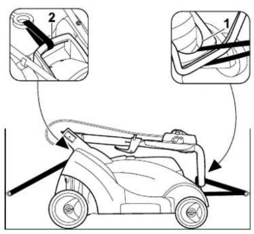


2000/14/EC, 2002/96/EC, 2004/108/EC,
2006/95/EC, 2006/42/EC, 2011/65/EC
natural_image
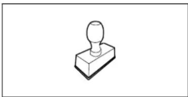
Simple line drawing of a mechanical component with a cylindrical top and rectangular base (no text or symbols)Thank you for choosing a VIKING quality product.
This product has been produced using state-of-the-art production methods and extensive quality assurance procedures, because our goal is only achieved if you, the customer, are satisfied with your machine.
If you have any questions concerning your machine, please contact your dealer or our sales agency directly.
I hope that your VIKING machine will give you great enjoyment.

Dr. Peter Pretzsch
Management
1. Table of contents
Notes on the instruction manual 28
General 28
Country-specific versions 28
Instructions for reading the instruction manual 28
Machine overview 28
For your safety 29
General 29
Transport 29
Preparations 30
Mowing procedure 30
Maintenance, cleaning, repairs and storage 31
Warning – dangers caused by electrical current 32
Disposal 32
Description of symbols 33
Standard equipment 33
Preparing the machine for operation 33
General 33
Installing mono handlebar (ME 339 C) 33
Installing dual handlebar (ME 339) 34
Assembling grass catcher box 34
Controls 34
Mono handlebar (ME 339 C) 34
Dual handlebar (ME 339) 35
Grass catcher box 35 Central cutting height adjustment 35
Notes on working with the machine 35
General 35 Mowing on slopes 36
Correct motor load 36
If the mowing blade blocks 36
Thermal motor overload protection 36
Safety devices 36
Two-hand operation 36
Motor run-down brake 36
Operating the machine 36
Electrical connection 36
Strain relief 37
Switching on lawn mower 37
Switching off lawn mower 37
Level indicator 37
Emptying grass catcher box 37
Maintenance 37
General 37 Cleaning the machine 37
Electric motor and wheels 38
Upper handlebar ME 339 38
Mowing blade maintenance 38
Removing and installing mowing blade 38
Sharpening mowing blade 39
Storage (winter break) 39
Transport 39 Carrying and securing lawn mower 39
Environmental protection 39
Minimising wear and preventing damage 40
Standard spare parts 40
CE - manufacturer's declaration of conformity 40
Technical specifications 41
Troubleshooting 41
Service schedule 42
Handover confirmation 42
Service confirmation 42
2. Notes on the instruction manual
2.1 General
This instruction manual constitutes original manufacturer's instructions in the sense of EC Directive 2006/42/EC.
VIKING is continually striving to further develop its range of products; we therefore reserve the right to make alterations to the form, technical specifications and equipment level of our standard equipment.
For this reason, the information and illustrations in this manual are subject to alterations.
2.2 Country-specific versions
VIKING supplies machines with different plugs and switches, depending on the country of sale.
Machines with European plugs are shown in the illustrations. Machines with other types of plug are connected to the mains in a similar way.
2.3 Instructions for reading the instruction manual
Illustrations and texts describe specific operating steps.
All symbols which are affixed to the machine are explained in this instruction manual.
Viewing direction:
Viewing direction when "left" and "right" are used in the instruction manual: the user is standing behind the machine and is looking forwards in the direction of travel.
Section reference:
References to relevant sections and subsections for further descriptions are made using arrows. The following example shows a reference to a section: ( 2.1)
Designation of text passages:
The instructions described can be identified as in the following examples.
Operating steps which require intervention on the part of the user:
- Release bolt (1) using a screwdriver, operate lever (2)...
General lists:
– Use of the product for sporting or competitive events
Texts with added significance:
Text passages with added significance are identified using the symbols described below in order to especially emphasise them in the instruction manual:

Danger
Risk of accident and severe injury to persons. A certain type of behaviour is necessary or must be avoided.

Warning
Risk of injury to persons. A certain type of behaviour prevents possible or probable injuries.

Caution
Minor injuries or material damage can be prevented by a certain type of behaviour.

Note
Information for better use of the machine and in order to avoid possible operating errors.
Texts relating to illustrations:
Illustrations relating to use of the machine can be found in the front of this instruction manual.
The camera symbol serves to link the figures on the illustration pages with the corresponding text passages in the instruction manual.

3. Machine overview
1 Upper handlebar
2 Lower handlebar
3 Housing
4 Motor hood
5 Rear wheel
6 Front wheel
7 Grass catcher box
8 Upper transport handle
9 Lower transport handle

10 Discharge flap
11 Rotary handle
12 Quick-clamping device
13 Motorstop lever
14 Height adjustment lever
15 Strain relief
16 Mains connection
17 Start button
18 Identification plate
4. For your safety
4.1 General

These safety regulations must be observed when working with the lawn mower.

Read the entire instruction manual before using the machine for the first time and keep it in a safe place for future reference.
Ensure that you are familiar with the controls and use of the machine.
Before initial use, advice should be obtained from the specialist dealer or other technician.
The lawn mower should not be operated after the consumption of alcohol, medications which impair reactions, or drugs.
Never mow in the vicinity of other persons, particularly children, or animals.
Be aware that the user of the machine is responsible for accidents involving other persons or their property.
Only give (or lend) the machine to persons who are familiar with this model and how to operate it. Always provide them with the instruction manual.
Caution – risk of accident:
The lawn mower is intended for private use and only for mowing lawns; its use for other purposes is not permitted and may be dangerous or result in damage to the machine.
Due to the physical danger to the user, the lawn mower must not be used, for example, for the following applications (incomplete list):
– for trimming bushes, hedges and shrubs,
– for cutting creepers,
– for the care of lawn roofs and balcony boxes,
– for clearing paths (vacuuming, blowing, clearing snow),
– for shredding or chopping tree or hedge cuttings,
– for levelling earth mounds, e.g. mole hills,
- for transporting clippings (except in the grass catcher box provided).
Caution – risk of accident:
Only use accessories which VIKING has supplied or authorised for use on this machine. Furthermore, modifications to the machine are not permitted.
Particular care is required during use in public green spaces, parks, sports fields, along roads and in agricultural and forestry businesses.

Caution: Danger to health due to vibrations.
Excessive exposure to vibrations
can result in damage to the cardiovascular or nervous system, particularly in persons with cardiovascular problems. Please consult a physician if you experience symptoms that may have been caused by vibrational loads. Symptoms of this kind principally affect the fingers, hands or wrists and include (incomplete list):
- numbness,
- p a i n ,
- muscular weakness,
- skin discolouration,
– unpleasant tingling sensation.
Children, persons with impaired physical, sensory or mental faculties or those lacking the appropriate experience, or persons who are not familiar with the instructions, must never be allowed to use the machine.
Never allow children under the age of 16 to use the machine. Local regulations may specify a minimum age for users.

Risk of death from suffocation!
Packaging material is not a toy - danger of suffocation! Keep packaging material away from children.
4.2 Transport

Always wear gloves to prevent injuries from sharp-edged components.
Switch off the machine prior to transport, disconnect the power cable and allow the blade to come to a standstill.
Note the information in the "Transport" section ( 13.) when lifting the machine.
Take the weight of the machine into account and use suitable loading aids (loading ramps, lifters) if necessary.
Avoid contact with the blade when lifting and carrying the machine.
Only transport the machine once the motor has cooled down.
Secure the machine and any machine components being transported (e.g. grass catcher box) on the load floor using adequately-dimensioned fastening material (belts, ropes etc.).
When transporting the machine, always observe regional legislation, especially regarding load security and the transport of objects on load floors.
4.3 Preparations
Persons who are not familiar with the instruction manual are not permitted to use the machine.
Observe the local regulations regarding permitted operating times for gardening power tools.

Always wear robust shoes and long trousers when mowing. Never mow barefoot or in
sandals.
Carefully inspect the complete area on which the machine is to be used and remove any large stones, sticks, wires, bones or other foreign objects which could be thrown up by the machine.
Before use, perform a visual check to ensure that the cutting tool, fastening screws and entire cutting unit are in good condition, check particularly for secure seating, damage and wear ( 12.5).
Replace all worn or damaged parts before using the machine. Replace any illegible or damaged danger signs and warnings on the machine. Your VIKING dealer has a stock of replacement stickers.
Never switch the motor on without a correctly installed blade. Risk of motor overheating.
Never use the mower with damaged safety devices, without functioning motor brake or attached safety devices, e.g. without the discharge flap or the grass-catching unit.
For safety reasons, always use an undamaged grass catcher box.
The switch mechanisms installed in the machine must not be removed or bypassed (e.g. by tying the motorstop lever to the handlebar).
Observe the instructions in section "Warning - dangers caused by electrical current" ( 4.6).
4.4 Mowing procedure
Keep others, particularly children, and animals out of the danger area. Make sure that others are not endangered.
Do not mow at ambient temperatures below +5°C (41°F).
Never mow wet grass or mow in the rain. The risk of accidents is higher if the grass is wet (increased danger of slipping for operator).
Only mow during the day or when there is enough light.
Place the machine on an even surface for start-up. The machine must not be tilted when starting the engine.
Exercise care when starting the motor. Observe the instructions in section "Initial operation of the machine" ( 11.). Keep your feet a safe distance from the cutting tool.
Only operate the machine at walking speed – never run when working with the machine. Working quickly with the machine increases the risk of injury due to stumbling, slipping etc.
Switch off the motor,
- if tilting of the mower is necessary when transporting over surfaces other than grass,
- when pushing the mower to and from mowing areas,
– before removing the grass catcher box.
Always ensure good stability on slopes. Avoid mowing on excessively steep slopes in order to prevent loss of control of the machine.
Be particularly careful when changing direction on a slope in order to prevent loss of control of the machine.
Only mow at right-angles to the slope and never up or down the slope, in order to avoid being run over by the running lawn mower in the case of loss of control of the machine or of falling.
Caution – Risk of stumbling!
Be particularly careful when moving backwards and when pulling the lawn mower.
Be particularly careful when turning the machine around or pulling it towards you.
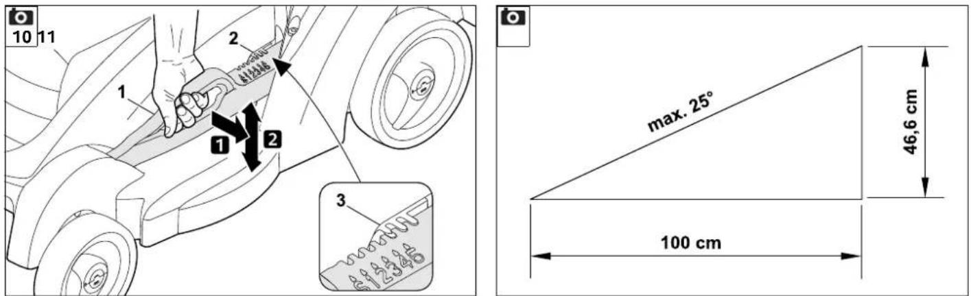
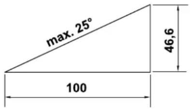
For safety reasons, the machine must not be used on slopes with an incline of more than 25^ (46.6%).
Risk of injury:
A slope inclination of 25^ corresponds to a vertical height increase of 46.6 cm for a 100 cm horizontal distance.

Beware of the work tools running on for several seconds before coming to a standstill.
STOP

Do not try to examine the blades while the lawn mower is operating. Never open the
discharge flap and/or remove the grass catcher box when the mowing blade is running. Rotating blades can cause injury.
Never attach any objects to the handlebar (e.g. work clothing). Extension cables must never be wrapped around the handlebar.
Regularly check that the blade is securely fastened and is not damaged or worn in any way ( 12.5).

Caution – risk of injury!
Never put hands or feet on or underneath rotating parts. Never touch the rotating blade.
Always keep away from the discharge opening. Always observe the safety distance provided by the handlebar.
Avoid switching on the machine repeatedly within a short period of time; in particular avoid "playing" with the start button. Risk of motor overheating.
Owing to the voltage fluctuations caused by this machine during the run-up period, other devices connected to the same circuit may be subject to interference in the case of unfavourable power supply conditions. In this case, appropriate steps should be taken (e.g. connection to a different circuit than the one used by the affected device, or operation of the machine using a circuit with a lower impedance).

Switch off the motor, disconnect the mains plug and ensure that the cutting tool has come to a complete standstill
– before remedying blockages, including those in the discharge chute,
- if the cutting tool has hit a foreign object. The cutting tool needs to be checked for possible damage. The lawn mower must not be operated with a damaged or bent blade shaft or motor shaft. Risk of injury through defective parts!
– Before you check, clean or carry out work on the mower, e.g. adjusting the cutting height, opening or closing the discharge flap;
- If the mower begins to vibrate excessively. In this case, the complete machine, in particular the cutting tool must be checked for possible damage and loose parts. Damaged parts must be replaced prior to further use, loose parts must be fastened/tightened.
– Before leaving the machine unattended;
– Before lifting, or carrying the machine;
– Before transporting the machine.
Never lift or carry a mower with the motor running or the mains lead connected.
It is not permitted to transport anything or anyone, particularly children, on the machine.
4.5 Maintenance, cleaning, repairs and storage

Before performing any work on the machine, before adjusting or cleaning the mower, or before
checking whether the electric cable is entwined or damaged, switch off the mower and disconnect the plug.

Always wear thick gloves when carrying out any work on the cutting tool.
Allow the machine to fully cool down before storing it in an enclosed space, performing maintenance on it or cleaning it.
Perform only those maintenance operations that are described in this instruction manual. Have all other operations carried out by a specialist dealer.
VIKING recommends that you have maintenance operations and repairs performed exclusively by a VIKING specialist dealer.
VIKING specialist dealers regularly attend training courses and are provided with technical information.
If you do not have the necessary expertise or auxiliary equipment, please always contact a specialist dealer. (VIKING recommends VIKING specialist dealers).
Only use high quality tools, accessories and spare parts. Otherwise, there may be a risk of accidents resulting in personal injury or damage to the machine.
VIKING recommends the use of genuine VIKING tools, genuine accessories and genuine spare parts. Their properties are optimally adapted to the machine and the user's requirements.
Genuine VIKING spare parts can be recognised by the VIKING spare parts number, by the VIKING lettering and, if present, by the VIKING spare parts symbol. On smaller parts, only the symbol may be present.
Ensure that all nuts, pins and bolts are securely tightened, so that the machine is in a safe operating condition.
Check the grass-catching unit regularly for wear, damage or for loss of functionality.
If the cutting tool or the lawn mower hits an obstacle or a foreign object, the motor must be switched off, the plug disconnected, and an inspection performed by a specialist.
Replace danger signs and warnings on the machine which have become illegible. Your VIKING dealer has a stock of replacement stickers.
The power cable should only be repaired or replaced by authorised electricians.
In order to prevent fire hazards, keep the area around the air vents between the motor cover and housing free from e.g. grass, straw, moss, leaves or emerging grease.
Components or guards that are removed for maintenance operations must be properly reinstalled immediately.
Carefully clean the lawn mower following use. Never use high-pressure cleaners and do not clean the lawn mower under running water (e.g. using a garden hose). Do not use aggressive cleaning agents.
These cleaners can damage plastics and metals, impairing the safe operation of your VIKING machine.
Check the entire machine for wear or damage on a regular basis, particularly before extended periods when the machine is not in use (over winter). Replace worn or damaged parts to ensure that the machine is always in a safe operating condition.
Store the cooled lawn mower safely in a dry, locked place that is inaccessible to children.
4.6 Warning – dangers caused by electrical current

Caution: Danger of electric shock! Particularly important for electrical safety are the mains cable, plug, on/off switch and
electric cable. Damaged cables, connectors and plugs, or electric cables that do not conform to regulations must not be used, to prevent any risk of electric shocks. Therefore, check the electric cable regularly for signs of damage or ageing (brittleness).
Never use a damaged extension cable. Replace defective cables with new ones and never repair extension cables.
Never use the machine if the cables are damaged or worn.
Danger of electric shock!
Do not connect a damaged cable to the mains and do not touch a damaged cable before disconnecting it from the mains.
Danger of electric shock!
Damaged cables, connectors and plugs, or electric cables which do not conform with regulations may not be used.
Keep the electric cable away from the blade when mowing.
Only use extension cables that are insulated against moisture for outdoor use which are suitable for use with the machine ( 11.1).

Although the drive motor is splashproof, do not use the lawn mower when it is raining or in wet environments.
Do not leave the machine unprotected in the rain.
Detach electric cables at the plug and socket and not by pulling on the electric cable.
Only connect the machine to a power supply that is protected by means of a residual current-operated protective device with a release current of a maximum of 30 mA. Your electrician can provide further information.
It must be noted that current fluctuations can damage the lawn mower when the machine is connected to a power generator.
Always ensure that the power cables used are adequately protected by a fuse.
For reasons of electrical safety, the electric cable must always be correctly installed on the handlebar ( 7.2).
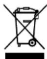
4.7 Disposal
Ensure that old machines are properly disposed of. Render the machine unusable prior to disposal. In order to prevent accidents, ensure that you remove the power supply cable or the electric cable from the on/off switch to the motor.
Risk of injury due to the mowing blade! Always store an old lawn mower in a safe place prior to scrapping. Ensure that the machine and the mowing blade are kept out of the reach of children.
5. Description of symbols
Caution!
Read the instruction manual before initial use.

Risk of injury!
Keep other persons out of the danger area.
Risk of injury!
Beware of the sharp mowing blade. The mowing blade runs on for several seconds after switching off (motor/blade brake). Before performing any work on the cutting tool, before carrying out maintenance and cleaning work, before checking whether the electric cable is entwined or damaged, or before leaving the machine unattended, switch off the motor and disconnect the plug.
Danger of electric shock! Keep the electric cable away from the cutting tool.
ME 339:
Start motor.
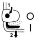
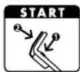
ME 339 C:
Start motor.
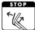
ME 339 C:
Stop motor.
6. Standard equipment
Item Designation
A Basic unit 1
B Upper part of grass catcher box 1
C Lower part of grass catcher box 1
D Pin 2
• Instruction manual 1
ME 339 C:
E Washer 2
F Screw 1
G Pin 1
H Clamping piece 2

Qty.
I Quick-clamping device 1
ME 339:
J Flat head bolt 2
K Cable guide 1
L Rotary handle 2
M Cable clip 1
7. Preparing the machine for operation
7.1 General

Risk of injury!
Observe the safety instructions in the section "For your safety" ( 4.).
- Place the machine on level and firm ground when performing all the operations described.
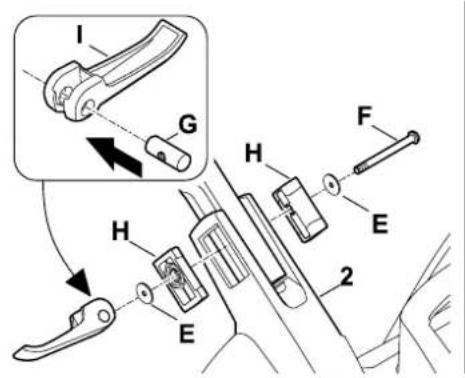
7.2 Installing mono handlebar (ME 339 C)
- Locate mono handlebar (1) in working position in handlebar console (2) and hold.
- Insert left and right clamping pieces (H) into handlebar console (2) as illustrated. Fit washer (E) onto screw (F) and guide screw (F) through clamping pieces and lower handlebar from the inside to the outside.
- Fit washer (E).
- Insert pin (G) in quick-clamping device (I) and screw both together onto screw (F).
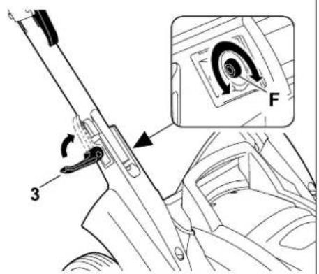
- Close quick-clamping device (3).

- Quick-clamping device (3) must be sufficiently tightened so that it closes completely and the handlebar is firmly attached to the handlebar console. If necessary, release quick-clamping device again and tighten or loosen screw (F).
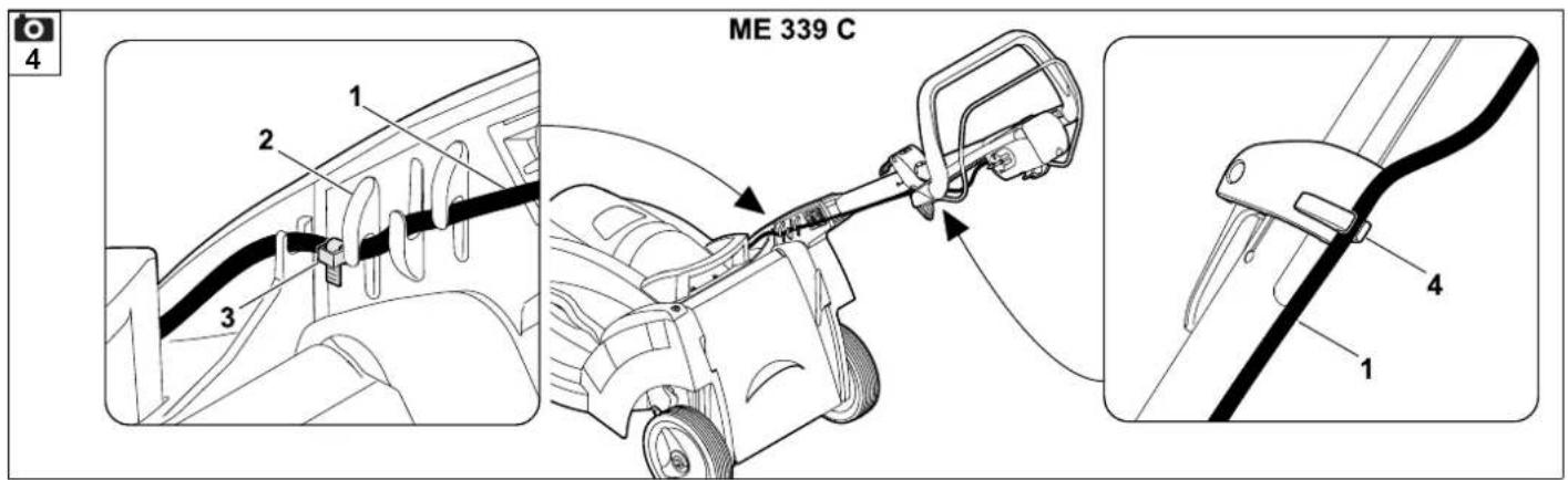
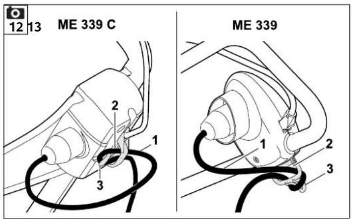
Installing electric cable:
- Insert electric cable (1) in strain relief moulding (2) of handlebar console as illustrated. Make sure the cable tie (3) is correctly positioned in the strain relief moulding.
- Press electric cable (1) into holder (4) on quick-release clamp body. The electrical cable must lie taught against the handlebar tube in the area of the lower handlebar.
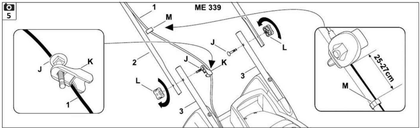
7.3 Installing dual handlebar (ME 339)

Installing upper handlebar:
- Insert flat head bolt (J) through cable guide (K) and attach electric cable (1).
- Fit dual handlebar (2) onto both lower handlebar sections (3). Insert flat head bolts (J) – on right with cable guide (K), on left without – through bores from the inside to the outside and tighten with rotary handles (L).
Installing cable clip:

Danger of electric shock!
In order to prevent damage to the insulating layer on the handlebar, only press on the cable clips by hand. Do not use any tools (e.g. hammer or screwdriver).
- Fasten electric cable (1) to upper handlebar with cable clip (M). Ensure a distance of 25 - 27 cm between cable clip and switch on upper handlebar.
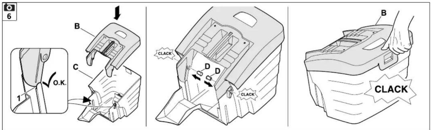
7.4 Assembling grass catcher box
- Fit upper part of grass catcher box (B) onto lower part of grass catcher box (C). Ensure correct position in guides (1).
- Push pin (D) through bores provided from inside.
- Allow upper part of grass catcher box (B) to engage in lower part of grass catcher box using slight pressure.
- Attach grass catcher box ( 8.3).
8. Controls
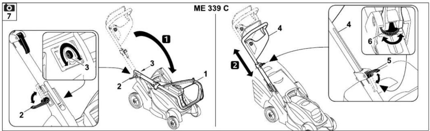
8.1 Mono handlebar (ME 339 C)
The ME 339 C lawn mower is equipped with an adjustable telescopic handlebar.


Danger of electric shock!
The electric cable must always be attached to the quick-release clamp body and the handlebar console. Some slack must be retained at the adjustment area of the telescopic handlebar at maximum handlebar length ( 7.2).

Danger of pinching!
The handlebar can fold down or retract when the quick-clamping device is released. For this reason, always hold the handlebar (1) with one hand at its highest point when you open the quick clamping device.
1 Folding down handlebar:
Transport position (for cleaning, for space-saving transport and for storage of the machine):
- Set handlebar to minimum height.
- Hold handlebar (1) with one hand and open quick-clamping device (2).
- Fold down handlebar (1) forwards.
- If necessary, quick-clamping device (2) can be closed and the handlebar set to the transport position.
Working position (to push machine):
- Fold up handlebar (1) rearwards and hold with one hand.
- Close quick-clamping device (2).
- Quick-clamping device (2) must be sufficiently tightened so that it closes completely and upper handlebar is firmly attached to handlebar console. If necessary, release quick-clamping device again and tighten or loosen screw (3).
- Adjust handlebar height.
2 Height adjustment:
The height of the telescopic handlebar is infinitely adjustable:
- Hold upper handlebar (4) with one hand and open quick-clamping device (5).
- Pull or push upper handlebar (4) out of/into lower handlebar to the desired handlebar height.
- Hold upper handlebar (4) with one hand and close quick-clamping device (5).
- Quick-clamping device (5) must be sufficiently tightened so that it closes completely and handlebar is firmly locked in lower handlebar. If necessary, release quick-clamping device again and turn knurled nut (6).
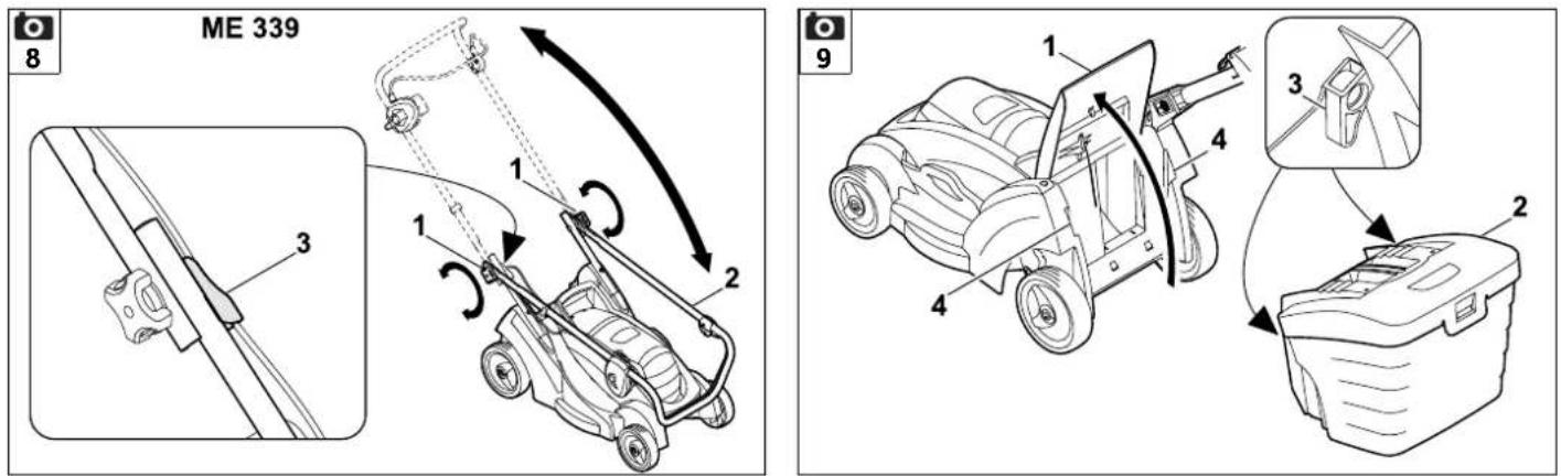
8.2 Dual handlebar (ME 339)


Danger of pinching!
The upper handlebar can be fold down when the rotary handles are released. For this reason, always hold the upper handlebar (2) with one hand at its highest point when you unscrew the rotary handles.
Folding down handlebar:
Transport position (for cleaning, for space-saving transport and for storage of the machine):
- Loosen rotary handles (1) until they can be moved easily backwards and forwards in machined grooves, then fold down upper handlebar (2) forwards.
Working position (to push machine):
- Fold up upper handlebar (2) rearwards and hold with one hand.
- Tighten rotary handles (1). Ensure correct position of cable guide (3).
8.3 Grass catcher box
Attaching:
- Open discharge flap (1) and hold it open.
- Attach grass catcher box (2) to mountings (4) on rear of machine by means of locating lugs (3).
- Close discharge flap (1).
Detaching:
- Open discharge flap (1) and hold it open.
- Lift grass catcher box (2) and remove rearwards.
- Close discharge flap (1).
8.4 Central cutting height adjustment

Five different cutting heights between 30 mm and 70 mm can be set.
Level 1 = lowest cutting height
Level 5 = highest cutting height
Lawn mowers for Great Britain:
Six different cutting heights between 20 mm and 70 mm can be set.
Level S = lowest cutting height
Level 5 = highest cutting height

In order to prevent damage, the lowest cutting height must only be used on even lawns (without bumps).
Setting cutting height:
- Push height adjustment lever (1) away from lawn mower slightly until lever is released from locating lugs (2).
- Increasing cutting height: Raise lawn mower using height adjustment lever (1) (push lever forwards).
Lower lawn mower using height adjustment lever (1) (push lever rearwards). - Push height adjustment lever (1) towards lawn mower slightly until locating lugs (2) engage in lever. The selected cutting height can be read off at the front locating lug (3).
Decreasing cutting height:
9. Notes on working with the machine
9.1 General

Risk of injury!
Untangle any knots in the cable immediately.
Guide the electric cable behind you when mowing. Electric cables can be inadvertently cut when mowing and present a tripping hazard. They therefore involve a high accident risk. For this reason, mow so that the electric cable is always visible in the area of grass that has already been cut.
To ensure a perfect, thick lawn, mow regularly and keep the grass short.
Do not cut the lawn too short in hot, dry conditions as it will dry out or burn in the sun and become unsightly.
The cutting pattern will be better with a sharp blade than with a blunt one; the blade should therefore be sharpened regularly (VIKING specialist dealer).
9.2 Mowing on slopes

For safety reasons, the lawn mower must not be used on inclines of more than 25°. A slope inclination of 25° (46.6%) corresponds to a vertical height increase of 46.6 cm for a 100 cm horizontal distance.
9.3 Correct motor load
Do not switch on the lawn mower in tall grass or at the lowest cutting height.
The lawn mower load must never cause the motor speed to drop significantly.
If the speed drops, select a higher cutting height setting and/or reduce the rate of feed.
9.4 If the mowing blade blocks
Switch off the motor immediately and disconnect the plug. Then eliminate the cause of the fault.
9.5 Thermal motor overload protection
If an overload of the motor occurs during operation, the built-in thermal overload protection device automatically deactivates the motor.
Causes for an overload:
– mowing excessively high grass or cutting height adjusted too low,
– excessive rate of feed,
– inadequate cleaning of the cooling air guide (inlet slots),
- mowing blade is blunt or worn,
- unsuitable or excessively long electric cable - voltage loss ( 11.1).
Recommencing operation
Resume normal operation of the machine following a cooling period of up to 10 min (depending on the ambient temperature) ( 11.).
10. Safety devices
10.1 Two-hand operation
The motor can only be switched on by pressing and holding the start button with the right hand and then pulling the motorstop lever to the handlebar with the left hand.
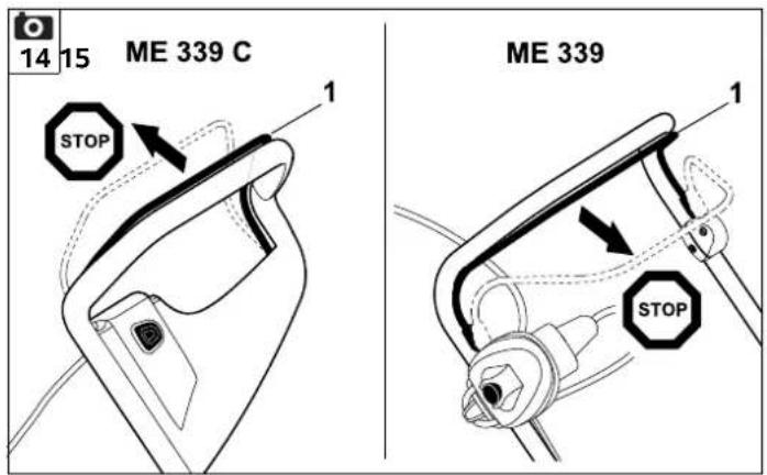
10.2 Motor run-down brake
When the motorstop lever is released, the mowing blade comes to a complete standstill in less than three seconds.
An integrated motor run-down brake shortens the run-down time until the blade stops.
11. Operating the machine
11.1 Electrical connection

Danger of electric shock!
Observe the safety instructions in the section "For your safety" ( 4.).
If using a cable drum, the connection cord must be unwound completely, otherwise electrical resistance may cause loss of power and overheating.
Only electric cables which are no lighter than rubber sheathed cables H07 RN-F DIN/VDE 0282 may be used as electric cables.
Recommended minimum cross-section:
up to 25 m Length: 3 x 1.5 mm ^4 up to 50 m Length: 3 x 2.5 mm ^2
The connectors of the electric cable must be made of rubber or have a rubber cover and conform to the standard DIN/VDE 0620.
The mains voltage and mains frequency must correspond to the information on the identification plate and the information contained in the section "Technical specifications" ( 18.).
The power cable must be adequately protected by a fuse ( 18.).
This machine is intended for operation with a power supply having a system impedance of Z_max at the transfer point (house connection) of maximum 0.49 ohms (at 50 Hz).
The user must ensure that the machine is only operated with a power supply which meets this requirement. If necessary, this information can be obtained from the local electric power company.
11.2 Strain relief

During work, the strain relief prevents any unintentional disconnection of the electric cable and any resulting damage to the mains connection on the machine.
For this reason, the electric cable must be fed through the strain relief.
- Form a loop in the electric cable (1) and guide it through the opening (2).
- Then push the loop over the hook (3) and pull it tight.
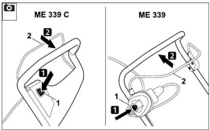
11.3 Switching on lawn mower


Do not start the motor in high grass or when the mower is set to the lowest cutting height, as this makes starting difficult.
- Press and hold down start button (1). Pull motorstop lever (2) to handlebar and hold.
- Start button (1) can be released once motorstop lever (2) is pressed.
11.4 Switching off lawn mower

- Release motorstop lever (1). Motor and mowing blade come to a stop after a short run-down time.
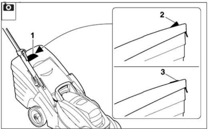
11.5 Level indicator

The grass catcher box features a level indicator (1) on the upper part of the catcher box.
The flow of air that is created by the rotary movement of the mowing blade and is responsible for filling the grass catcher box raises the level indicator (2): The grass catcher box is filled with clippings.
When the grass catcher box is full, this flow of air is reduced and the level indicator drops (3):
• Empty filled grass catcher box ( 11.6).
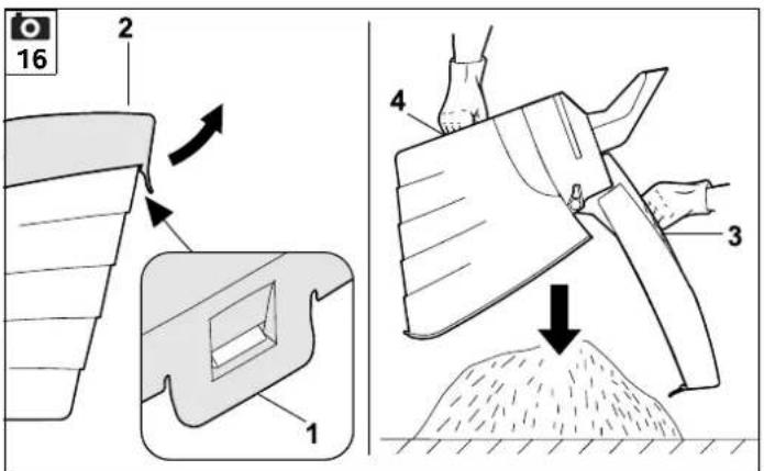
11.6 Emptying grass catcher box

- Switch off motor ( 11.4) and detach grass catcher box ( 8.3).
- Open grass catcher box at tab (1) and open upper part of the grass catcher box (2) upwards.
- Hold grass catcher box by handles in upper part of grass catcher box (3) and in lower part of grass catcher box (4) and empty it.
12. Maintenance
12.1 General

Risk of injury!
Observe the safety instructions in the section "For your safety" ( 4.).
Annual service by the specialist dealer:
The lawn mower should be inspected once annually by a specialist dealer. VIKING recommends VIKING specialist dealers.
12.2 Cleaning the machine

Maintenance interval:
After each use
- Detach grass catcher box ( 8.3).

Risk of injury:
Before tipping up the mower, place it on firm, level and flat ground. The machine may tip over when working on it in the cleaning position. Always stand to the side of the machine. Never work in front of or behind the mower.
Cleaning position ME 339 C:
- Fold down mono handlebar ( 8.1).
- Lift discharge flap (1), tilt mower upwards and set down on handlebar console (2).
- Leave handlebar (3) resting on the ground and fasten in this position with quick-clamping device (4).
Cleaning position ME 339:
- Fold down the dual handlebar ( 8.2).
- Tilt lawn mower upwards and set down on lower handlebars (5).
Notes on cleaning:
Clean the machine thoroughly each time it has been used. Care of the machine will protect it against damage and extend its service life.
Remove dirt from the cooling air guide (inlet slots) between the motor cover and the lower housing to ensure that the motor is adequately cooled.
Clean the mowing blade.
Clean the underside of the mower with water and a brush. Detach accumulated cutting deposits in the housing and in the ejection chute beforehand using a stick.
Never spray water onto motor components, seals, bearing points or electrical parts such as switches. This would result in expensive repairs.
If you are unable to remove the dirt with water using a brush or a cloth, VIKING recommends the use of a special cleaner (e.g. STIHL special cleaner).
12.3 Electric motor and wheels
The electric motor is maintenance-free.
The wheel bearings are maintenance-free.
12.4 Upper handlebar ME 339
Maintenance interval: Before each use
The upper handlebar is coated with a insulating layer. Should this layer become damaged, the upper handlebar must be replaced.
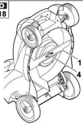
12.5 Mowing blade maintenance
Maintenance interval: Before each use

- Tilt mower upwards into cleaning position ( 12.2).
- Clean mowing blade (1) and check it for damage (notches or cracks) and wear; replace if necessary.
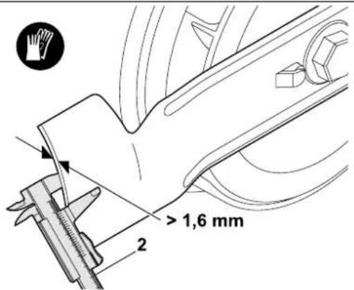
- Use a slide calliper (2) to measure blade thickness at 5 points at least. In particular, minimum thickness must also be ensured in the area of the blade wings.
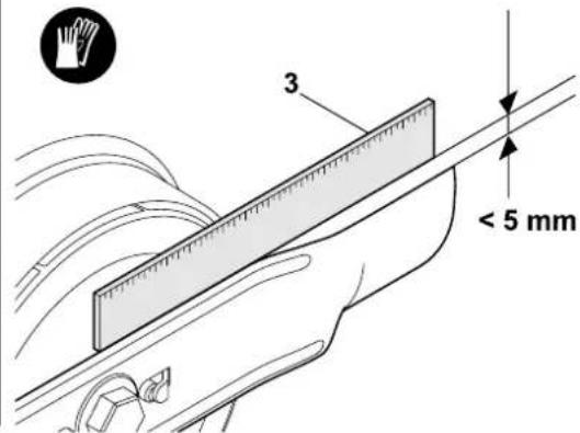
- Place a ruler (3) against the front blade edge and measure permissible grinding.
Wear limits:
The blade thickness must be at least 1.6 mm at any point.
The cutting edges may not be ground back by more than 5 m m during sharpening.
If the supplied standard blade is not installed in the lawn mower, but e.g. the mulching blade, which is available as a special accessory, different wear limits apply (see instruction manual Kit 339).

Risk of injury:
A worn or damaged blade may break off and cause serious injuries. The instructions for blade maintenance must therefore always be observed.
In particular, the lawn mower must not be operated if parts of the cutting unit (comprising the mowing blade, blade fastening screw and blade mounting) are damaged or worn.
Blades are subjected to differing degrees of wear depending on the location and duration of use. If you use the mower on sandy ground or use it frequently under dry conditions, the blade will be subjected to greater loads and will wear more quickly than the average.
Always replace the blade fastening screw (4) when replacing the mowing blade.
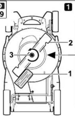
12.6 Removing and installing mowing blade


In order to prevent damage to the blade fastening screw, use a suitable hexagon socket (22 mm) for loosening and tightening.
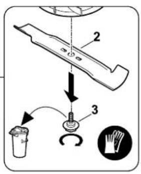
1 Removing:
- Use a suitable wooden block (1) to counterhold mowing blade (2).
- Unscrew blade fastening screw (3) and remove mowing blade (2).
2 Installing:

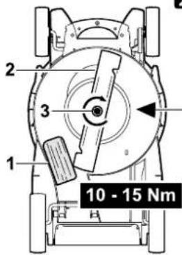
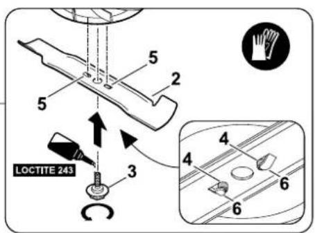
Risk of injury:
The mowing blade (2) must only be installed as shown. The tabs (6) must face downwards and the curved wings must point upwards.
Observe the specified torque of 10 - 15 Nm when tightening the blade fastening screws, as the secure attachment of the cutting tool depends on this. Additionally secure the blade fastening screw (3) with Loctite 243.
- Clean blade contact surface and blade bushing.
- Install mowing blade (2) with curved wings pointing upwards. Locating lugs (4) must be located in bores (5) of mowing blade.
- Use a suitable wooden block (1) to counterhold mowing blade (2).
- Tighten blade fastening screw (3) to a torque of 10 - 15 Nm.
12.7 Sharpening mowing blade

Risk of injury:
Check blade for damage before installing. The blade must be replaced if notches or cracks are identified, if the blade is worn back by 5 mm, or if the blade is thinner than 1.6 mm at any point ( 12.5).
VIKING recommends having the mowing blade sharpened by a technician. Operation of the machine is impaired in the case of an incorrectly sharpened blade (incorrect sharpening angle, imbalance etc.).
Sharpening instructions:
- Remove mowing blade ( 12.6).
- Cool the mowing blade when sharpening, e.g. with water. The blade must not be allowed to display blue colouring, as this would reduce its cutting quality.
- Sharpen the blade evenly to prevent vibrations due to imbalance.
- Observe sharpening angle of 30^ .
- After sharpening, remove any sharpening burr at the cutting edge using fine sandpaper if necessary.
12.8 Storage (winter break)
Store the machine in a dry and locked place that is generally free of dust. Make sure that it is kept out of the reach of children.
Only store the lawn mower in good operating condition, fold down the handlebar if necessary.
Keep all nuts, pins and bolts tightly fastened, replace danger signs and warnings on the machine that have become illegible, check the entire machine for wear and damage. Replace all worn or damaged parts.
Any machine faults must be completely remedied prior to storage.
Note the following points when storing the lawn mower for long periods (winter break):
- Clean all external parts of the machine with care.
- Thoroughly lubricate/grease all moving parts.
13. Transport
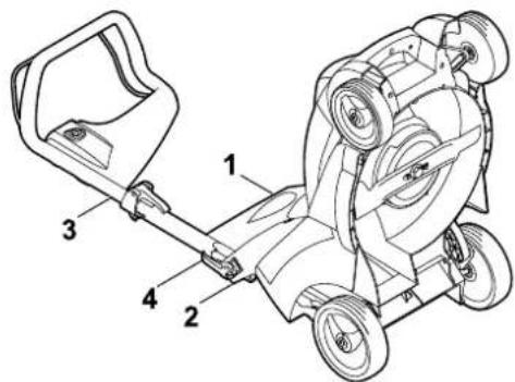
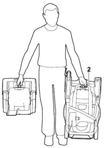
13.1 Carrying and securing lawn mower


Risk of injury:
Observe the safety instructions in the section "For your safety" ( 4.).
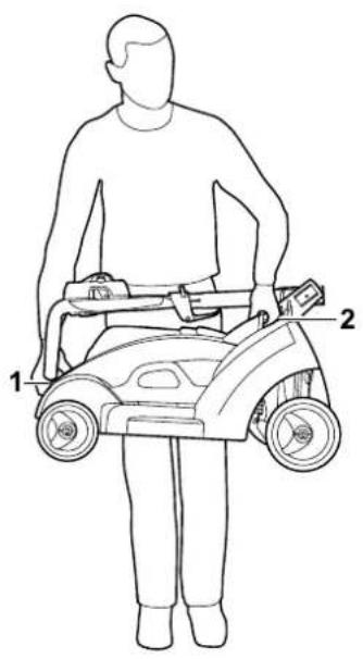
Carrying the machine:
- Only lift the lawn mower by the transport handles (1, 2). Always ensure sufficient distance between the mowing blade and your body, particularly your feet and legs.
- Carry the lawn mower using both hands, with one hand at the upper transport handle (2) and the other hand at the lower transport handle (1),
or
- carry the lawn mower with one hand at the upper transport handle (2).
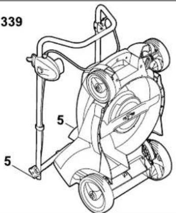
Securing the machine (lashing):
- Secure the lawn mower on the load floor using suitable fastening materials.
- Attach ropes or straps at the handles (1, 2).
14. Environmental protection
Lawn clippings should be composted and not disposed of in household waste.
The machine, its packaging and accessories are all produced from recyclable materials and must be disposed of accordingly.
By disposing of materials separately, and in an environmentally friendly manner, valuable resources can be re-used. For this reason, the machine should be disposed of for recycling at the end of its useful life. Pay particular attention to the information in the "Disposal" section during disposal ( 4.7).
Consult your recycling centre or your specialist dealer for information on the proper disposal of waste products.
15. Minimising wear and preventing damage
Please always observe the following important information for the prevention of damage or excessive wear to your VIKING machine:
1. Wearing parts
Some parts of the VIKING machine are subject to normal wear even when used properly and must be replaced in due time depending on type and duration of use.
These include:
- B | a d e
- Grass catcher box
2. Compliance with the information in this instruction manual
The VIKING machine must be used, maintained and stored with the care described in this instruction manual. Any damage caused by non-compliance with the safety, operating and maintenance instructions is the sole responsibility of the user.
This applies in particular to:
– inadequately dimensioned power cables (cross section),
– incorrect electrical connection (voltage),
– product modifications not approved by VIKING,
– the use of tools or accessories which are not approved or suitable for the machine, or are of inferior quality,
- improper use of the product,
– use of the product for sporting or competitive events,
– resultant damage due to continued use of the product with defective components.
3. Maintenance operations
All operations listed in the section "Maintenance" must be performed regularly.
If these maintenance operations cannot be carried out by the user, a specialist dealer must be commissioned to perform them.
VIKING recommends that you have maintenance operations and repairs performed exclusively by a VIKING specialist dealer.
VIKING specialist dealers regularly attend training courses and are provided with technical information.
If these operations are neglected, faults may arise which are the responsibility of the user.
These include:
– damage to the drive motor as a result of inadequate cleaning of the cooling air guide (inlet slots),
– corrosive and other resultant damage caused by incorrect storage,
– damage to the machine through the use of inferior-quality spare parts,
– damage due to untimely or inadequate maintenance or damage due to maintenance or repair work not performed in the workshops of specialist dealers.
16. Standard spare parts
Mowing blade
6320 702 0100
Blade fastening screw
6310 710 2800

The fastening elements for the mowing blade (e.g. blade fastening screw) must be replaced when replacing the blade, i.e. when installing the blade. Spare parts are available from a VIKING specialist dealer.
17. CE - manufacturer's declaration of conformity
We,
VIKING GmbH
Hans Peter Stihl-Strasse 5
declare that the machine,
Lawn mower, manually-operated and mains-powered (ME)
manufacturer's brand:
Type: ME 339.0
VIKING
manufacturer's brand: VIKING
ME 339.0 C
Serial number 6320
conforms to the following EU guidelines: 2000/14/EC, 2002/96/EC, 2004/108/EC, 2006/95/EC, 2006/42/EC, 2011/65/EC
The product has been developed in conformance with the following standards: EN 60335-1, EN 60335-2-77
Applicable conformity assessment procedure:
Appendix VIII (2000/14/EC)
Name and address of relevant, named location:
Compilation and storage of technical documentation: Johann Weiglhofer VIKING GmbH
The year of manufacture and serial number appear on the identification plate of the machine.
Measured sound power level: 92.5 dB(A)
Guaranteed sound power level: 93 dB(A)
Langkampfen, 2015-01-02 (YYYY-MM-DD)
VIKING GmbH

Research and Product Development Manager
18. Technical specifications
ME 339.0 / ME 339.0 C:
| Serial number 6320 | |
| Motor, design | Electric motor |
| Manufacturer | Cleva |
| Universal AC | |
| Type | motor |
| Voltage | 230 V~ |
| Power input | 1200 W |
| Frequency | 50 Hz |
| Fuse | 5 A |
| Protection class | II |
| Type of protection | IPX 4 |
| Cutting utilities | Cutter bar |
| Cutting width | 37 cm |
| Speed of cutting utilities | 3200 rpm |
| In accordance with Directive 2000/14/EC: | |
| Guaranteed sound power level L_WAd | 93 dB(A) |
| In accordance with Directive 2006/42/EC: | |
| Sound pressure level at workplace L_pA | 79 dB(A) |
| Uncertainty K_pA | 1 dB(A) |
| Cutter bar drive | permanent |
| Tightening torque for blade fastening screw | 10 - 15 Nm |
| Wheel diameter (front) | 150 mm |
| Wheel diameter (rear) | 180 mm |
ME 339.0 / ME 339.0 C:
| Grass catcher box | 40 l |
| Cutting height | 30 - 70 mm |
| Cutting height (Great Britain only) | 20 - 70 mm |
ME 339.0:
| Specified vibration characteristic in accordance with EN 12096: | |
| measured value a_hw | 0.82 m/sec ^2 |
| Uncertainty K_hw | 0.41 m/sec ^2 |
| Measurement in accordance with EN 20643 | |
| L/W/H | 122/42/107 cm |
| Weight | 14 kg |
| Weight (Great Britain only) | 15 kg |
ME 339.0 C:
| Specified vibration characteristic in accordance with EN 12096: | |
| measured value a_hw | 0.55 m/sec ^2 |
| Uncertainty K_hw | 0.28 m/sec ^2 |
| Measurement in accordance with EN 20643 | |
| L/W/H | 128/42/107 cm |
| Weight | 14 kg |
19. Troubleshooting
✗ If necessary, contact a specialist dealer; VIKING recommends VIKING specialist dealers.
Fault:
Motor will not start
Possible cause:
- N o m a i n s v o l t a g e
- Connection cable, plug, plug connector or switch defective
- Start button not pressed
- Motor is overloaded because the grass is too tall or too wet
– Motor overload protection activated
– Mower housing is blocked
– Fuse in plug faulty (GB version)
Remedy:
- Check fuse ( 11.1)
- Check cable/plug/switch and replace if necessary ( 11.1)
- Press start button (⇒ 11.3)
- Do not start motor in high grass, adapt cutting height ( 8.4)
- Allow machine to cool ( 9.5)
– Clean mower housing (⇒ 12.2) - Replace fuse in plug (✗)
Fault:
Frequently tripped mains fuse
Possible cause:
– Unsuitable electric cable
- Power overload
– Machine is overloaded due to mowing grass which is too long or too wet
Remedy:
- Use suitable electric cable ( 11.1)
- Connect machine to another circuit
- Adapt cutting height and mowing speed to mowing conditions ( 8.4)
Fault:
Excessive vibration during operation
Possible cause:
- Blade fastening screw is loose
- Blade is not balanced
Remedy:
- Tighten blade fastening screw ( 12.6)
- Re-sharpen (balance) or replace blade (⇒ 12.7)
Fault:
Poor cut, lawn turning yellow
Possible cause:
- mowing blade is blunt or worn,
– rate of feed is too high in relation to the cutting height
Remedy:
- Re-sharpen or replace mowing blade (⇒ 12.7)
- Reduce rate of feed and/or select correct cutting height ( 8.4)
Fault:
Starting problems or deteriorating motor power
Possible cause:
- Mowing grass which is too long or too wet
- Mower housing is blocked
Remedy:
- Adapt cutting height and mowing speed to mowing conditions ( 8.4)
– Clean mower housing (disconnect mains plug before cleaning) ( 12.2)
Fault:
Ejection chute blocked
Possible cause:
- Mowing blade is worn
- Mowing grass which is too long or too wet
Remedy:
- Replace mowing blade ( 12.7)
- Adapt cutting height and mowing speed to mowing conditions ( 8.4)
20. Service schedule
20.1 Handover confirmation
Model:
Serial number:
Date:

natural_image
Simple line drawing of a mechanical component with a cylindrical top and rectangular base (no text or symbols)Next service
Date: ____ ____ ____ ____ ____
20.2 Service confirmation
Please hand this instruction manual to your VIKING specialist dealer in the case of maintenance work.
He will confirm the service operations performed in the pre-printed boxes.

Service performed on

Next service date

Chère cliente, cher client,
natural_image
Simple line drawing of a mechanical component with a flanged top and base (no text or symbols)Prochain entretien
Date : ____ ____ ____ ____ ____
Meting conform EN 20643
l/b/h 122/42/107 cm
Gewicht 14 kg
Meting conform EN 20643
l/b/h 128/42/107 cm
Gewicht 14 kg
19. Defectopsporing
natural_image
Simple line drawing of a mechanical component with a cylindrical top and rectangular base (no text or symbols)natural_image
Simple line drawing of a mechanical component with a cylindrical top and rectangular base (no text or symbols)Prossima revisione
Data:
2000/14/EC, 2002/96/EC, 2004/108/EC,
2006/95/EC, 2006/42/EC, 2011/65/EC
2015-01-02 (AAAA-MM-DD)
VIKING GmbH
Weiglhofer
Director del Departamento de
natural_image
Simple line drawing of a mechanical component with a cylindrical top and rectangular base (no text or symbols)Próxima revisión
Fecha: ____ ____ ____ ____ ____
natural_image
Simple line drawing of a mechanical component with a cylindrical top and rectangular base (no text or symbols)2000/14/EC, 2002/96/EC, 2004/108/EC,
2006/95/EC, 2006/42/EC, 2011/65/EC
natural_image
Simple line drawing of a mechanical component with a cylindrical top and rectangular base (no text or symbols)Neste service
Dato: ____ ____ ____ ____ ____
Varning! Hälsorisk pga vibration!
natural_image
Simple line drawing of a mechanical component with a cylindrical top and rectangular base (no text or symbols)Nästa service
Datum: ____ ____ ____ ____ ____
20.2 Servicebekräftelse
2000/14/EC, 2002/96/EC, 2004/108/EC,
2006/95/EC, 2006/42/EC, 2011/65/EC
Anvendt procedure for
overensstemmelsesvurdering:
Tillæg VIII (2000/14/EC)
natural_image
Simple line drawing of a mechanical component with a cylindrical top and rectangular base (no text or symbols)Næste service
Dato: ____ ____ ____ ____ ____
natural_image
Simple line drawing of a mechanical component with a cylindrical top and rectangular base (no text or symbols)Następny przegląd
Data: ____ ____ ____ ____ ____
natural_image
Simple line drawing of a mechanical component with a cylindrical top and rectangular base (no text or symbols)Đalší servis
Dátum: ____ ____ ____ ____ ____
natural_image
Simple line drawing of a mechanical component with a cylindrical top and rectangular base (no text or symbols)natural_image
Simple line drawing of a mechanical component with a cylindrical top and rectangular base (no text or symbols)Sljedeći servis
Datum: ____ ____ ____ ____ ____
20.2 Potvrda servisa
Prilikom radova održavanja dajte ove upute za uporabu svom ovlaštenom VIKING serviseru.
natural_image
Simple line drawing of a mechanical component with a cylindrical top and rectangular base (no text or symbols)Dalši servis Datum: ____ ____ ____ ____ ____
2000/14/EC, 2002/96/EC, 2004/108/EC,
2006/95/EC, 2006/42/EC, 2011/65/EC.
natural_image
Simple line drawing of a mechanical component with a cylindrical top and rectangular base (no text or symbols)Nākamā apkope

natural_image
Simple line drawing of a mechanical component with a cylindrical top and rectangular base (no text or symbols)corespunde cu următoarele directive CE: 2000/14/EC, 2002/96/EC, 2004/108/EC, 2006/95/EC, 2006/42/EC, 2011/65/EC
Conform directivei 2000/14/EC:
Nivel maxim de
Conform directivei 2006/42/EC:
Nivelul presiunii
muncă L_pA 79 dB(A)
Incertitudine K_pA 1 dB(A)
natural_image
Simple line drawing of a mechanical component with a cylindrical top and rectangular base (no text or symbols)2000/14/EC, 2002/96/EC, 2004/108/EC,
2006/95/EC, 2006/42/EC, 2011/65/EC
natural_image
Simple line drawing of a mechanical component with a cylindrical top and rectangular base (no text or symbols)Επόμενη συντήρηση
2000/14/EC, 2002/96/EC, 2004/108/EC,
2006/95/EC, 2006/42/EC, 2011/65/EC
natural_image
Simple line drawing of a mechanical component with a cylindrical top and rectangular base (no text or symbols)Следующий техосмотр
Дата: ____ ____ ____ ____ ____
2000/14/EC, 2002/96/EC, 2004/108/EC,
2006/95/EC, 2006/42/EC, 2011/65/EC
natural_image
Simple line drawing of a mechanical component with a cylindrical top and rectangular base (no text or symbols)Следващ сервис
дата:
natural_image
Simple line drawing of a mechanical component with a cylindrical top and rectangular base (no text or symbols)natural_image
Simple line drawing of a mechanical component with a cylindrical top and rectangular base (no text or symbols)Järgmine teenindus
natural_image
Simple line drawing of a mechanical component with a cylindrical top and rectangular base (no text or symbols)Növbeti xidmæt
Tarix: ____ ____ ____ ____ ____
natural_image
Product lineup of five lawn lawn tools including a grass lawn, grassing equipment, and a tiller (no visible text or labels)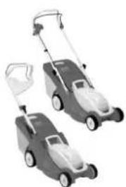
natural_image
Two lawn curlers with adjustable arm and wheels, shown in grayscale (no text or symbols visible)
0478 121 9917 E
E
INT 1