GB 320 - Blower MCCULLOCH - Free user manual and instructions
Find the device manual for free GB 320 MCCULLOCH in PDF.
| Product type | Leaf blower |
| Brand and model | McCulloch GB 320 |
| Engine | 2-stroke, 25 cc, 0.6 kW |
| Maximum engine speed | 8000 rpm |
| Spindle speed | 10,000 rpm |
| Weight (without accessory) | 3.9 kg |
| Fuel tank capacity | 340 ml |
| Fuel | Mixture of unleaded gasoline 90 octane and 2-stroke oil at 50:1 |
| Ignition | Champion spark plug, gap 0.6 mm |
| Guaranteed sound power level | 115 dB(A) |
| Sound pressure level at operator's ear | 100 dB(A) |
| Vibration level (left/right handle) | 8.9 / 7.5 m/s² |
| Main functions | Blowing leaves, debris, grass; sweeping use |
| Safety | ON/OFF switch, mandatory eye and ear protection, safety distance of 15 m |
| Maintenance | Clean air filter every 5 h, replace spark plug annually, empty tank before storage |
| Spare parts | Cutting head (not applicable for blower), air filter, spark plug, spool of line (for brushcutter) |
| Repairability | Carburetor adjustment possible, other repairs by authorized dealer |
| Certification | CE compliant with directives 2006/42/EC, 2014/30/EU, 2000/14/EC |
Frequently Asked Questions - GB 320 MCCULLOCH
User questions about GB 320 MCCULLOCH
0 question about this device. Answer the ones you know or ask your own.
Ask a new question about this device
Download the instructions for your Blower in PDF format for free! Find your manual GB 320 - MCCULLOCH and take your electronic device back in hand. On this page are published all the documents necessary for the use of your device. GB 320 by MCCULLOCH.
USER MANUAL GB 320 MCCULLOCH
GB Operator's manual 2-13
SE Bruksanvisning 14-25
DK Brugsanvisning 26-38
FI Kayttoohje 39-51
NO Bruksanvisningen 52-63
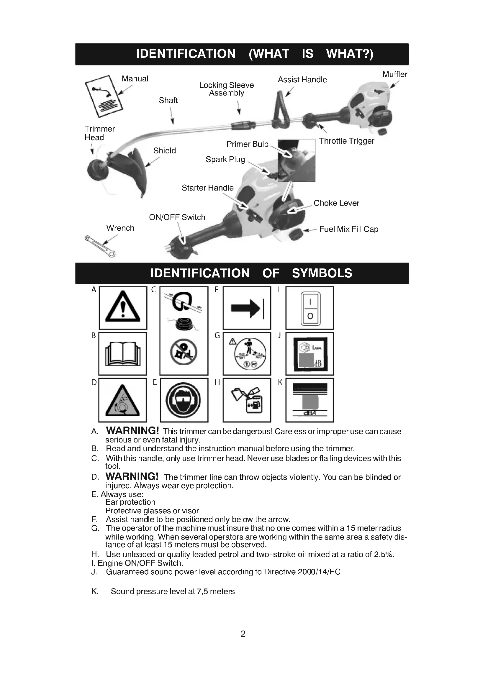
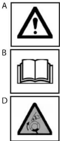
A. WARNING! This trimmer can be dangerous! Careless or improper use can cause serious or even fatal injury.
B. Read and understand the instruction manual before using the trimmer.
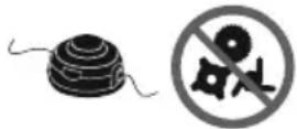
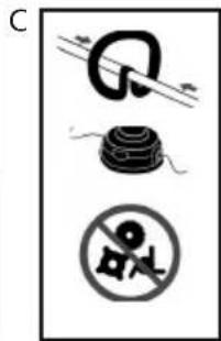
C. With this handle, only use trimmer head. Never use blades or flailing devices with this tool.
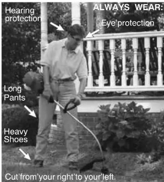
D. WARNING! The trimmer line can throw objects violently. You can be blinded or injured. Always wear eye protection.
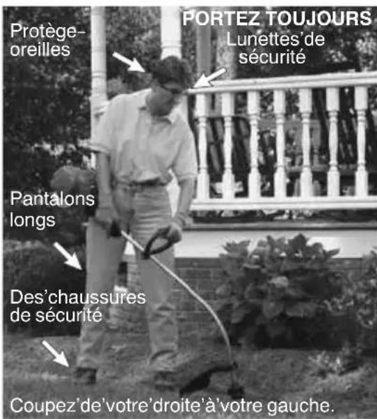
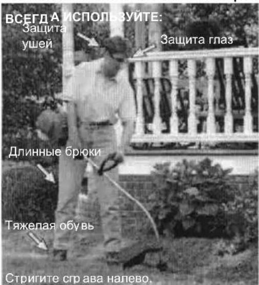
E. Always use:
Ear protection
Protective glasses or visor
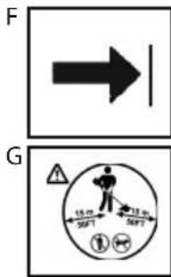
F. Assist handle to be positioned only below the arrow.
G. The operator of the machine must insure that no one comes within a 15 meter radius while working. When several operators are working within the same area a safety distance of at least 15 meters must be observed.
H. Use unleaded or quality leaded petrol and two-stroke oil mixed at a ratio of 2.5% .
I. Engine ON/OFF Switch.
J. Guaranteed sound power level according to Directive 2000/14/EC
K. Sound pressure level at 7,5 meters
SAFETY RULES

WARNING: When using gardening liances, basic safety precautions should always be followed to reduce the risk of fire andous injury. Read and follow all instructions.
This power unit can be dangerous! Operator responsible for following instructions and warnings on unit and in manual. Read entire instruction manual before using unit! Be thoroughly familiar with the controls and the proper use of the unit. Restrict the use of this unit to persons who read, understand, and follow instructions and warnings on unit and in manual. Never allow children to operate this unit.
INSTRUCTION MANUAL
SAFETY INFORMATION ON THE UNIT

DANGER: Never use blades, wire, or
flailing devices. This unit is designed for line trimmer use only. Use of any other accessories or attachments will increase the risk of injury.

WARNING: Trimmer line throws obs. violently. You and others can be blinded/red. Wear safety glasses and leg protec. 1. Keep body parts clear of rotating line.
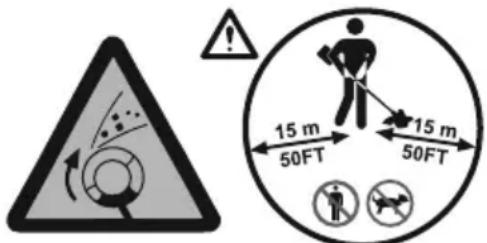
Keep children, bystanders, and animals 15 meters away. If approached stop unit immediately. If situations occur which are not covered in this manual, use care and good judgement. If you needassistance, contact your authorized service dealer.
OPERATOR SAFETY

WARNING: This machine produces
an electromagnetic field during operation. Under some circumstances, this field may interfere with active or passive medical implants. To reduce the risk of serious or fatal injury, we recommend persons with medical implants to consult their physician and the medical implant manufacturer before operating this machine.
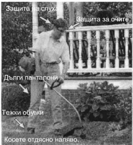
- Dress properly. Always wear safety glasses or similar eye protection when operating, or performing maintenance, on your unit (safety glasses are available). Eye protection should be marked Z87.
Always wear face or dust mask if operation is dusty. - Always wear heavy, long pants, long sleeves, boots, and gloves. Wearing safety leg guards is recommended.
Always wear foot protection. Do not go barefoot or wear sandals. Stay clear of spinning line. - Secure hair above shoulder length. Secure or remove loose clothing or clothing with loosely hanging ties, straps, tassels, etc. They can be caught in moving parts.
- Being fully covered also helps protect you from debris and pieces of toxic plants thrown by spinning line.
- Stay alert. Do not operate this unit when you are tired, ill, upset or under the influence of alcohol, drugs, or medication. Watch what you are doing; use common sense.
- Wear hearing protection.
- Mufflers fitted with catalytic converters get very hot during use and remain so for some time after stopping. This also applies at idle speed. Contact can result in burns to the skin. Remember the risk of fire!
- Never start or run inside a closed room or building. Breathing exhaust fumes can kill.
- Keep handles free of oil and fuel.
UNIT / MAINTENANCE SAFETY
- Disconnect the spark plug before performing maintenance except carburetor adjustments.
- Look for and replace damaged or loose parts before each use. Look for and repair fuel leaks before use. Keep in good working condition.
- Replace trimmer head parts that are chipped, cracked, broken, or damaged in any other way before using the unit.
- Maintain unit according to recommended procedures. Keep cutting line at proper length.
- Use only 2mm diameter line. Never use wire, rope, string, etc.
Install required shield properly before using the unit. Use only specified trimmer head; make sure it is properly installed and securely fastened.
Make sure unit is assembled correctly as shown in this manual. - Make carburetor adjustments with lower end supported to prevent line from contacting any object.
- Keep others away when making carburetor adjustments.
- Use only recommended accessories and replacement parts.
- Have all maintenance and service not explained in this manual performed by an authorized service dealer.
FUEL SAFETY
- Mix and pour fuel outdoors.
- Keep away from sparks or flames.
- Use a container approved for fuel
- Do not smoke or allow smoking near fuel or the unit.
- Avoid spilling fuel or oil. Wipe up all fuel spills.
- Move at least 3 meters away from fueling site before starting engine.
- Stop engine and allow to cool before removing fuel cap.
Always store gasoline in a container approved for flammable liquids.
CUTTING SAFETY
WARNING: Inspect the area before each use. Remove objects (rocks, broken glass, nails, wire, etc.) which can be thrown by or become entangled in line. Hard objects can damage the trimmer head and be thrown causing serious injury.
- Use only for trimming, scaling, mowing and sweeping. Do not use for edging, pruning or hedge trimming.
- Keep firm footing and balance. Do not overreach.
- Keep all parts of your body away from muffler and spinning line. Keep engine below waist level. A hot muffler can cause serious burns.
- Cut from your right to your left. Cutting on left side of the shield will throw debris away from the operator.
- Use only in daylight or good artificial light.
- Use only for jobs explained in this manual.
TRANSPORTING AND STORAGE
- Allow the engine to cool; secure unit before storing or transporting in vehicle.
- Empty fuel tank before storing or transporting the unit. Use up fuel left in the carburetor by starting engine and letting it run until it stops.
- Store unit and fuel in an area where fuel vapors cannot reach sparks or open flames from water heaters, electric motors or switches, furnaces, etc.
- Store unit so line limiter cannot accidentally cause injury. Unit can be hung by the shaft.
- Store the unit out of the reach of children.
- Secure the machine during transport.
SPECIAL NOTICE: Exposure to vibrations through prolonged use of gasoline powered hand tools could cause blood vessel or nerve damage in the fingers, hands, and joints of people prone to circulation disorders or abnormal swellings. Prolonged use in cold weather has been linked to blood vessel damage in otherwise healthy people. If symptoms occur such as numbness, pain, loss of strength, change in skin color or texture, or loss of feeling in the fingers, hands, or joints, discontinue the use of this tool and seek medical attention. An anti-vibration system does not guarantee the avoidance of these problems. Users who operate power tools on a continual and regular basis must monitor closely their physical condition and the condition of this tool.
ASSEMBLY
WARNING: Make sure unit is properly assembled and all fasteners are secure.
Examine parts for damage. Do not use damaged parts.
It is normal for the fuel filter to rattle in the empty fuel tank.
Finding fuel or oil residue on muffler is normal due to carburetor adjustments and testing done by the manufacturer.
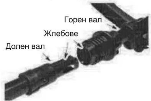
SHAFT ASSEMBLY
CAUTION: When assembling shaft, place the unit on a flat surface for stability.
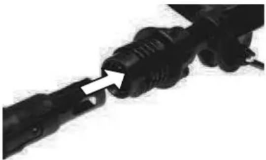
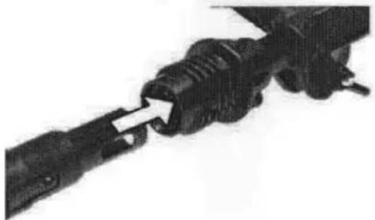
- Align grooves on upper and lower shafts.
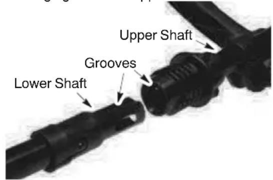
- Push the two shafts together until the lower shaft is fully seated in the upper shaft (the shafts lock into place).
- Slide lower locking sleeve assembly over upper locking sleeve assembly and tighten by turning clockwise.
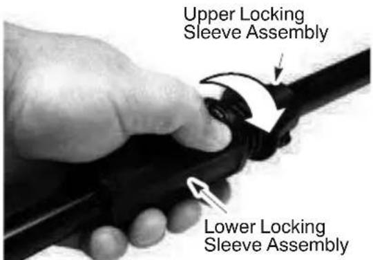
NOTE: If locking sleeve assembly will not tighten, the shafts are not fully seated.
ADJUSTING THE HANDLE
WARNING: When adjusting the assist handle, be sure it remains above the locking sleeve assembly and below the mark or arrow on the shaft.
-
Loosen wing nut on handle.
-
Rotate the handle on the shaft to an upright position; retighten wing nut.
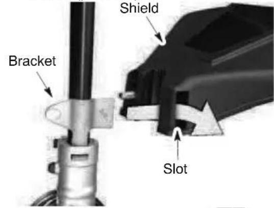
ATTACHING THE SHIELD
WARNING: The shield must be properly installed. The shield provides partial protection from the risk of thrown objects to the operator and others and is equipped with a line limiter which cuts excess line. The line limiter (on underside of shield) is sharp and can cut you.
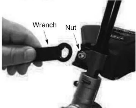
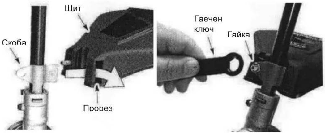
- Remove nut from shield.
- Insert bracket into slot on shield.
- Pivot shield until bolt passes through hole in bracket.
- Reinstall nut and tighten securely with wrench (provided).
OPERATION
WARNING: Be sure to read the fuel information in the safety rules before you begin. If you do not understand the safety rules, do not attempt to fuel your unit. Contact an authorized service dealer.
FUELING ENGINE
WARNING: Remove fuel cap slowly when refueling.
This engine is certified to operate on unleaded petrol. Before operation, petrol must be mixed with a good quality 2-cycle air-cooled engine oil designed to be mixed at a ratio of 50:1. A 50:1 ratio is obtained by mixing 5 liters of unleaded petrol with 0,1 liter of oil. DO NOT USE automotive oil or marine oil. These oils will cause engine damage. When mixing fuel, follow instructions printed on oil container. Once oil is added to petrol, shake container momentarily to assure that the fuel is thoroughly mixed. Always read and follow the safety rules relating to fuel before fueling your unit.
CAUTION: Never use straight petrol in your unit. This will cause permanent engine damage.
FUEL REQUIREMENTS
Use good quality unleaded petrol. The lowest recommended octane grade is 90 (RON).
IMPORTANT
Use of alcohol blended fuels (more than 10% alcohol) can cause major engine performance and durability problems.
WARNING: Incorrect use of fuel and/or lubricants will cause problems such as: improper clutch engagements, overheating, vapor lock, power loss, lubrication deficiency, deterioration of fuel lines, gaskets and internal carburetor components, etc. Alcohol blended fuels will cause a high absorption of moisture in the fuel/oil mixture, causing the separation of oil and fuel.
HOW TO STOP YOUR UNIT
- To stop the engine, move the ON/OFF switch to the OFF position.
HOW TO START YOUR UNIT

WARNING: The 'trimmer' head will
turn while starting the engine. Avoid any contact with the muffler. A hot muffler can cause serious'burns.
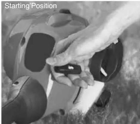
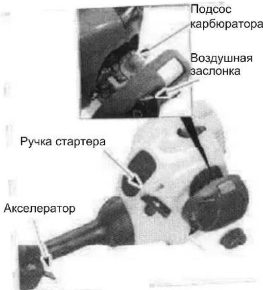
STARTING A COLD ENGINE (or a warm engine after running out of fuel)
- Set'unit on'a'flat surface.
- Move ON/OFF switch to the ON position.
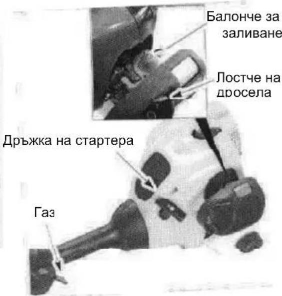
- 'Slowly'press'the'primer bulb 6'times.
- 'Move'choke'lever'to'FULL'CHoke'position.
- 'Squeeze'and'hold'trigger'through'all remaining steps.
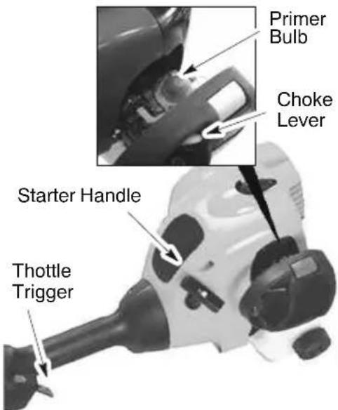
- 'Pull starter' rope handle sharply until engine sounds as if it is trying to start, but do not pull rope more than 6 times.
- 'As soon as engine sounds as if it is trying to start, move choke lever to HALF CHoke.
- 'Pull'starter'rope'sharply'until'engine'runs, but'no'more'than6'pulls.Ifthe'engine doesn't'ststart'after6'pulls'(at'the'HALF CHoke position), move the choke lever to
the'FULL'CHoke'position'and'press'the primer bulb 6 times. Squeeze and hold the throttle trigger and pull the starter rope2 more times.Move the choke lever to the HALF CHoke position and pull the starter rope until the engine runs, but no more than 6pulls. NOTE: If engine'sill doesn't start, it is probably flooded. Proceed to STARTING'A FLOODED ENGINE.
- 'Once'the'engine starts, 'allow it'to'run 10 seconds, then move the choke lever to RUN. 'Allow the unit to run for 60 more seconds at RUN before releasing the throttle trigger. NOTE: If engine dies with the choke lever in the RUN position, move the choke lever to the HALF'CHoke position and pull the rope until engine runs, but no more than 6' pulls.
STARTING A WARM ENGINE
- Move ON/OFF switch to the ON position.
- 'Move the choke lever to the HALF CHOKE position.
- 'Squeeze'and'hold'the'throttle'trigger. Keep'thruttle'trigger'fully'squeezed'until the engine runs'moonthly.
- 'Pull'starter'rope'sharily'until engine'runs, but no'more than5'pulls.
- Allow engine to run 15 seconds, then move the'choke'lever to'the RUN'position.
NOTE: If engine has not started, pull starter rope'5'moe'pulls. If enginestill'does'not-run,it is'probably'flooded.
STARTING A FLOODED ENGINE
Flooded'engines'can'be'started'by'placing the choke lever in the RUN position; then, pull the'rope'to'clear'the'engine'of'excess'fuel. Thiscould'require'pulling'the'starter'handle many times depending on how badly the unit is flooded. If the unit still doesn't start, refer to TROUBLESHOOTINGTABLE.
OPERATING INSTRUCTIONS
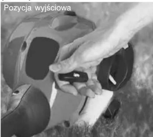
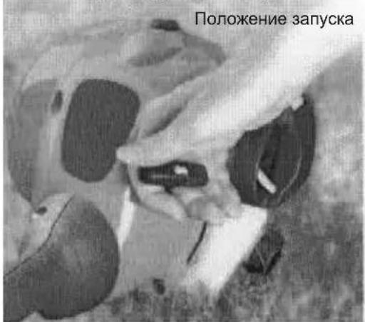
OPERATING POSITION
WARNING: Always wear eye protection and hearing protection. Never lean over the trimmer head. Rocks or debris can ricochet or be thrown into eyes and face and cause blindness or other serious injury. Do not run the engine at a higher speed than necessary. The cutting line will cut efficiently when the engine is run at less than full throttle. At lower speeds, there is less engine noise and vibration. The cutting line will last longer and will be less likely to "weld" onto the spool. Always release the throttle trigger and allow the engine to return to idle speed when not cutting. To stop engine:
- Release the throttle trigger.
- Move the ON/OFF switch to the OFF position.
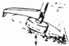
Advance line by tapping the bottom of the cutting head lightly on the ground while engine is running at full speed. The metal line limiter blade attached to the guard will cut the line to the proper length.
WARNING: Use only 2mm diameter line. Other sizes and shapes of line will not advance properly and will result in improper cutting head function or can cause serious injury. Do not use other materials such as wire, string, rope, etc. Wire can break off during cutting and become a dangerous missile that can cause serious injury.
CUTTING METHODS
WARNING: Use minimum speed and do not crowd the line when cutting around hard objects (rock, gravel, fence posts, etc.), which can damage the trimmer head, become entangled in the line, or be thrown causing a serious hazard.
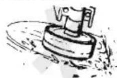
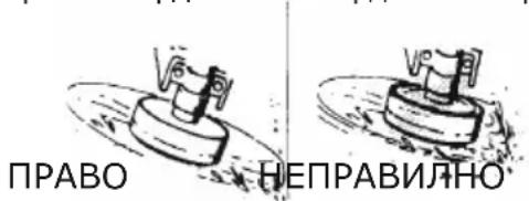
- The tip of the line does the cutting. You will achieve the best performance and minimum line wear by not crowding the line into the cutting area. The right and wrong ways are shown below.
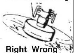
Tip of the Line Does The Cutting
Line Crowded Into Work Area
The line will easily remove grass and weeds from around walls, fences, trees and flower beds, but it also can cut the tender bark of trees or shrubs and scar fences.
- For trimming or scalping, use less than full throttle to increase line life and decrease head wear, especially:
During light duty cutting.
- Near objects around which the line can wrap such as small posts, trees or fence wire.
- For mowing or sweeping, use full throttle for a good clean job.
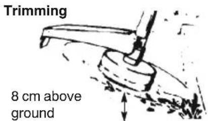
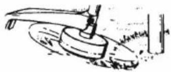
TRIMMING - Hold the bottom of the trimmer head about 8 cm above the ground and at an angle. Allow only the tip of the line to make contact. Do not force trimmer line into work area.
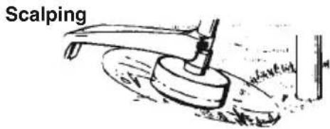
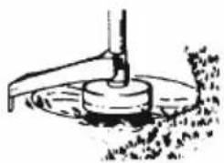
SCALPING - The scalping technique removes unwanted vegetation. Hold the bottom of the trimmer head about 8 cm above the ground and at an angle. Allow the tip of the line to strike the ground around trees, posts, monuments, etc. This technique increases line wear.
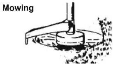
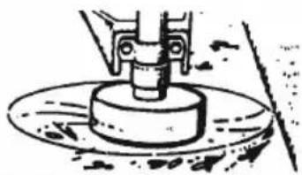
MOWING - Your trimmer is ideal for mowing in places conventional lawn mowers cannot reach. In the mowing position, keep the line parallel to the ground. Avoid pressing the head into the ground as this can scalp the ground and damage the tool.
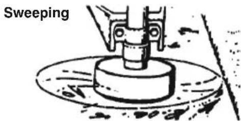
SWEEPING - The fanning action of the rotating line can be used for a quick and easy clean up. Keep the line parallel to and above the surfaces being swept and move the tool from side to side.
MAINTENANCE

WARNING: Disconnect the spark
plug before performing maintenance except for carburetor adjustments.
CHECK FOR LOOSE FASTENERS AND PARTS
Spark Plug Boot
Air Filter
Housing Screws
Assist Handle Screw
- Debris Shield
CHECK FOR DAMAGED OR WORN PARTS
Contact an authorized service dealer for replacement of damaged or worn parts.
- ON/OFF Switch -- Ensure ON/OFF switch functions properly by moving the switch to the OFF position. Make sure engine stops; then restart engine and continue.
- Fuel Tank -- Discontinue use of unit if fuel tank shows signs of damage or leaks.
- Debris Shield -- Discontinue use of unit if debris shield is damaged.
INSPECT AND CLEAN UNIT AND LABELS
After each use, inspect complete unit for loose or damaged parts. Clean the unit and labels using a damp cloth with a mild detergent.
- Wipe off unit with a clean dry cloth.
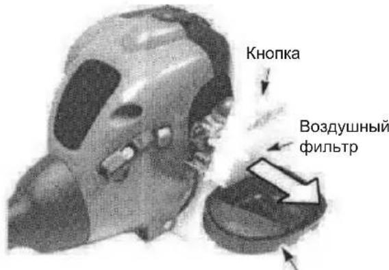
CLEAN AIR FILTER
A dirty air filter decreases engine performance and inc reases fuel consumption and harmful emissions. Always clean after every 5 hours of operation.
- Clean the cover and the area around it to keep dirt from falling into the carburetor chamber when the cover is removed.
- Remove parts as illustrated.
NOTE: Do not clean filter in gasoline or other flammable solvent toavoid creating a fire hazard or producing harmful evaporative emissions.
- Wash the filter in soap and water.
- Allow filter to dry.
- Replace parts.

REPLACE SPARK PLUG
Replace the spark plug each year to ensure the engine starts easier and runs better. Set spark plug gap at 0,6 mm. Ignition timing is fixed and nonadjustable.
- Twist, then pull off spark plug boot.
- Remove spark plug from cylinder and discard.
- Replace with Champion QCJ-6Yspark plug and tighten securely with a 19 mm socket wrench.
- Reinstall the spark plug boot.
SERVICE AND ADJUSTMENTS
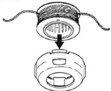
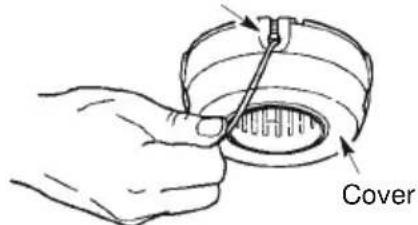
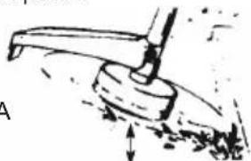
REPLACING THE LINE
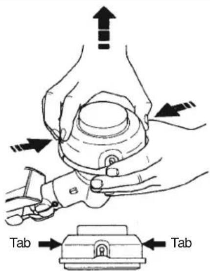
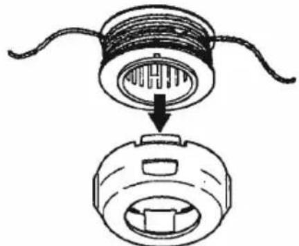
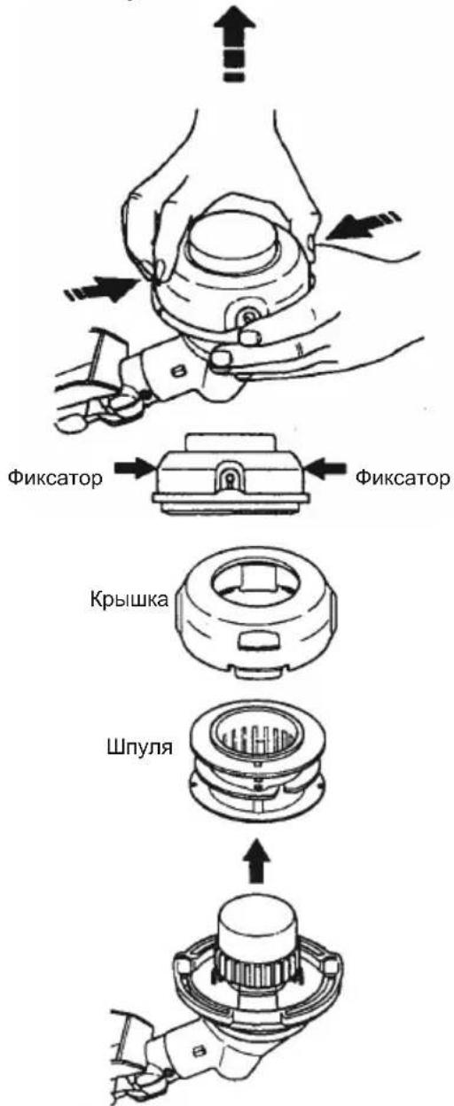
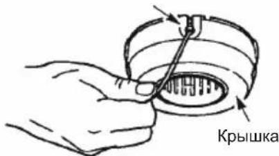
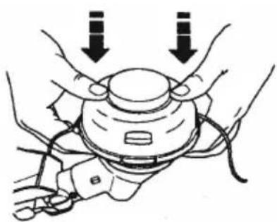
- Press the tabs on the side of the trimmer head and remove cover and spool.
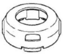
Cover
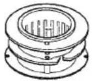
Spool
↑

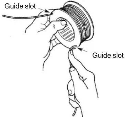
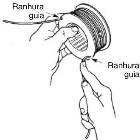
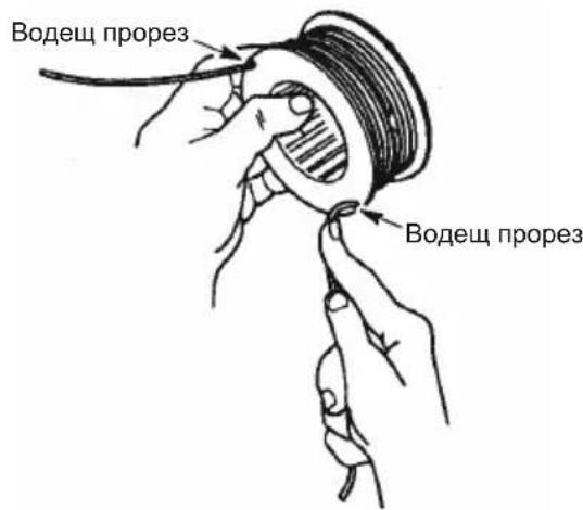
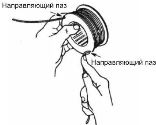
8. Position the lines in the guide slots.
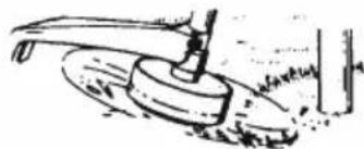
- Remove any remaining line.
- Clean dirt and debris from all parts. Replace spool if it is worn or damaged.
- Replace with a pre-wound spool, or replace line using a 8 meters length of 2mm diameter line.

WARNING: Never use wire, rope,
string, etc., which can break off and become a dangerous missile.
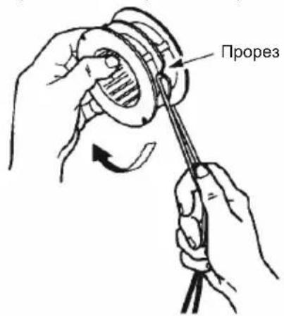
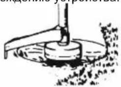
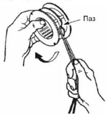
- When installing new line on an existing spool, hold the spool as shown.
- Bend the line at the midpoint and insert the bend into the slot in the center rim of the spool. Ensure line snaps into position in the slot.
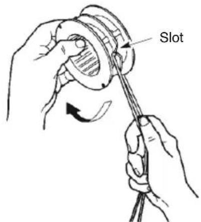
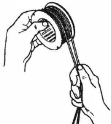
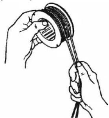
7. With your finger between the lines, wrap the lines evenly and firmly around the spool in a clockwise direction.
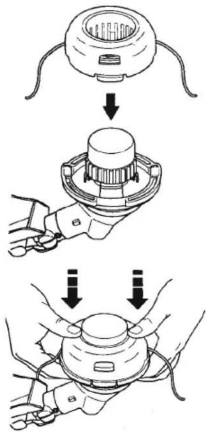
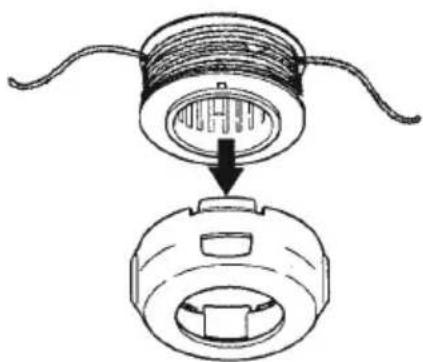
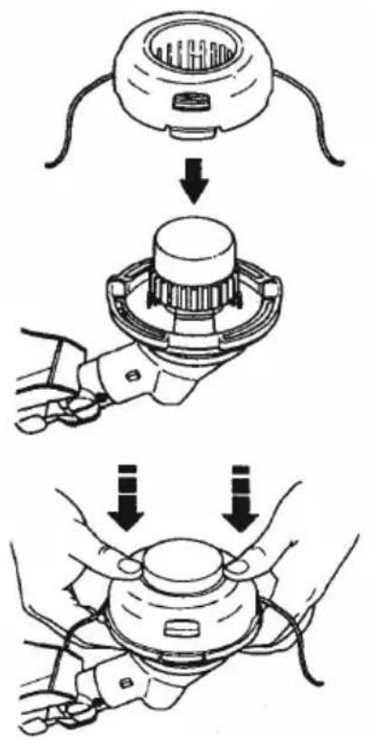
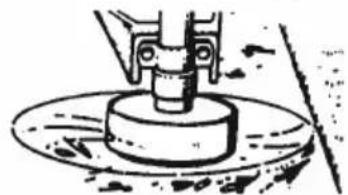
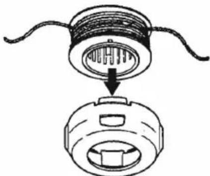
9. Place the spool in the cover as shown below.
10. Insert the ends of the lines through exit holes in the sides of the cover.
Line exit hole
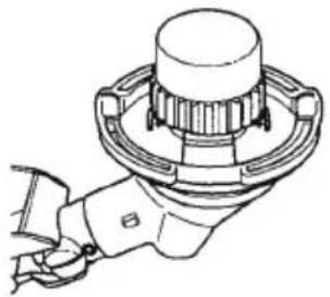
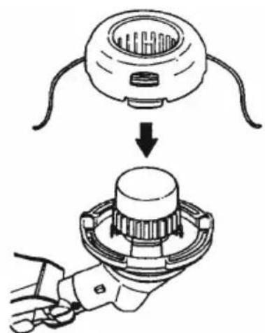
11. Reinstall the spool and cover onto the trimmer head. Push until cover snaps into place.

CARBURETOR ADJUSTMENT
WARNING: Keep others away when
making idle speed adjustments. The trimmer head will be spinning during this procedure. Wear your protective equipment and observe all safety precautions.
The carburetor has been carefully set at the factory. Adjustments may be necessary if you notice any of the following conditions:
- Engine will not idle when the throttle is released.
Make adjustments with the unit supported so the cutting attachment is off the ground and will not make contact with any object. Hold the unit by hand while running and making adjustments. Keep all parts of your body away from the cutting attachment and muffler.
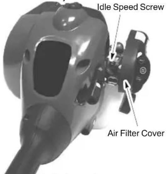
Idle Speed Adjustment
Allow engine to idle. Adjust speed until engine runs without stalling (idle speed too slow).
- Turn idle speed screw clockwise to increase enginespeed if engine stalls ordies.
- Turn idle speed screw counterclockwise to decrease engine speed.
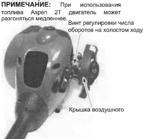
NOTE: When using Aspen 2T fuel, the engine acceleration may be slower.
If you require further assistance or are unsure about performing this procedure, contact an authorized service dealer.
STORAGE

WARNING: Perform the following
steps after each use:
- Allow engine to cool before storing or transporting.
- Store unit and fuel in a well ventilated area where fuel vapors cannot reach sparks or open flames from water heaters, electric motors or switches, furnaces, etc.
- Empty fuel tank before storing or transporting the unit.
- Store unit and fuel well out of the reach of children.
- Store unit with all guards in place. Position unit so that any sharp object cannot accidentally cause injury.
SEASONAL STORAGE
Prepare unit for storage at end of season or if it will not be used for 30 days or more.
If your unit is to be stored for a period of time:
Clean the entire unit before lengthy storage.
- Store in a clean dry area.
Lightly oil external metal surfaces.
ENGINE
- Remove spark plug and pour 1 teaspoon of 50:1, 2-cycle engine oil (air cooled) through the spark plug opening. Slowly pull the starter rope 8 to 10 times to distribute oil.
- Replace spark plug with new one of recommended type and heat range.
Clean air filter. - Check entire unit for loose screws, nuts, and bolts. Replace any damaged, broken, or worn parts.
- At the beginning of the next season, use only fresh fuel having the proper gasoline to oil ratio.
OTHER
- Do not store gasoline from one season to another.
- Replace your gasoline can if it starts to rust.
TROUBLESHOOTING TABLE

WARNING: Always stop unit and disconnect spark plug before performing all of the recommended remedies below except remedies that require operation of the unit.
| TROUBLE CAUSE REMEDY | ||
| Engine will not start. | 1. ON/OFF switch in OFF position. 2. Engine flooded. 3. Fuel tank empty. 4. Spark plug not firing. 5. Fuel not reaching carburetor. 6. Carburetor requires adjustment. 1. Carburetor requires adjustment. 2. Crankshaft seals worn. 3. Compression low. | 1. Move ON/OFF switch to ON position. 2. See “Starting a Flooded Engine” in Operation Section. 3. Fill tank with correct fuel mixture. 4. Install new spark plug. 5. Check for dirty fuel filter; replace. Check for kinked or split fuel line; repair or replace. 6. Contact an authorized service dealer. |
| Engine will not idle properly. | 1. See “Carburetor Adjustment” in Service and Adjustments Section. 2. Contact an authorized service dealer. 3. Contact an authorized service dealer. | |
| Engine will not accelerate, lacks power, or dies under a load. | 1. Air filter dirty. 2. Spark plug fouled. 3. Carburetor requires adjustment. 4. Carbon build-up on muffler outlet screen. 5. Compression low. | 1. Clean or replace air filter. 2. Clean or replace plug and regap. 3. Contact an authorized service dealer. 4. Contact an authorized service dealer. 5. Contact an authorized service dealer. |
| Engine smokes excessively. | 1. Choke partially on. 2. Fuel mixture incorrect. 3. Air filter dirty. 4. Carburetor requires adjustment. | 1. Adjust choke. 2. Empty fuel tank and refill with correct fuel mixture. 3. Clean or replace air filter. 4. Contact an authorized service dealer. |
| Engine runs hot. | 1. Fuel mixture incorrect. 2. Spark plug incorrect. 3. Carburetor requires adjustment. 4. Carbon build-up on muffler outlet screen. | 1. Empty fuel tank and refill with correct fuel mixture. 2. Replace with correct spark plug. 3. Contact an authorized service dealer. 4. Contact an authorized service dealer. |
DECLARATION OF CONFORMITY
EC Declaration of Conformity
Issuer's name: Husqvarna AB, SE-561 82 Huskvarna,Sweden (Tel: +46-36-146500)
Husqvarna AB claims sole responsibility for the trimmer and/or brushcutter platform(s) LT25NCOP
representing model(s) TRIMMAC from 2013 serial numbers and on-wards. The platform number and model number are clearly stated in plain text on the type plate along with the year with subsequent serial numbers.
The object of the declaration described above is in conformity with the requirements of the Council's
Directives:
2006/42/EC relating to machinery (2006-05-17)
2014/30/EU relating to electromagnetic compatibility (2014-02-26)
2000/14/EC relating to the noise emissions in the environment (2000-05-08)
In accordance with Annex V, the declared sound values are stated in the technical data sheet of the operator's manual.
The following standards have been applied:
EN ISO 12100:2010, EN ISO 11806-1:2011, CISPR 12:2007, ISO 14982:2009
Notified Body: TUV Rheinland LGA Products GmbH
Notified Body for Machinery (notified under 0197)
Tillystraße 2 - 90431 Nürnberg, Germany
TÜV Rheinland N.A. has carried out a voluntary type examination on behalf of Husqvarna AB, providing AK72133347.01 - Certificate for type examination. This voluntary type examination certificate is applicable to all manufacturing locations and Countries of Origin, as stated on the product. The supplied trimmer and/or brushcutter conform to the example that underwent EC type examination.
Signed on behalf of: Husqvarna AB, Huskvarna, Sweden, 01-10-2013

Ronnie E. Goldman, Director of Engineering (Authorized representative and responsible for technical documentation)
TECHNICAL DATA SHEET
MODEL:TRIMMAC(LT25NCOP)
ENGINE
Cylinder displacement, cm^3 25
At'maximum engine power, 'rpm'8000
Maximum rotational frequency of the spindle, rpm 10000
Engine speed at recommended maximum spindle
rotational frequency, 'rpm'10000
Recommended'speed'idling,'rpm'4000
Maximum engine power,measured in
accordance with ISO'8893, kW'0 ,6
Catalytic converter muffler'Yes
IGNITION SYSTEM
Spark'plug'Champion
Electrode'gap, mm'0,6
FUEL AND LUBRICATION SYSTEM
Fuel tank'volume'capacity,'cm3 340
Fuel consumption at maximum engine power, measured in accordance with ISO'8893, g/h'407
Specified fuel consumption at max. engine power, measured in accordance with ISO'8893, g/kWh'768
WEIGHT
Weight without fuel, cutting attachment and guard, kg 3,9
NOISE EMISSIONS
(see Note 1)
Sound power level, measured dB(A) 109
Sound power level, guaranteed L_WA dB(A) 115
SOUND LEVELS
(see Note 2)
Equivalent sound pressure level at the operator's ear, measured according to'EN'ISO'11806 and'ISO'22868, dB(A)
Equipped with trimmer head (original) 100
VIBRATION LEVELS
(see Note 3)
Equivalent vibration levels (a_hv,eq) at handles,measured according to'EN'ISO'11806 and ISO'22867, m/s2
Equipped with trimmer head (original), left/right 8,9/7,5
Note 1: Noise emissions in the environment measured as sound power (L_WA) in conformity with EC directive 2000/14/EC. Reported sound power level for the machine has been measured with the original cutting attachment that gives the highest level. The difference between guaranteed and measured sound power is that the guaranteed sound power also includes dispersion in the measurement result and the variations between different machines of the same model according to Directive'2000/14/EC.
Note 2: Reported data for equivalent sound pressure level for the machine has a typical statistical dispersion (standard deviation) of 1 dB(A).
Note 3: Reported data for equivalent vibration level has a typical statistical dispersion (standard deviation) of 1m / s^2
| Model TRIMMAC (5/16 RH arbor shaft thread) | ||
| Approved accessories | Type | Cutting attachment / guard, part. no. |
| Trimmer head | TNG7 (Ø 2 mm line) | 537419223 / 530096229 |
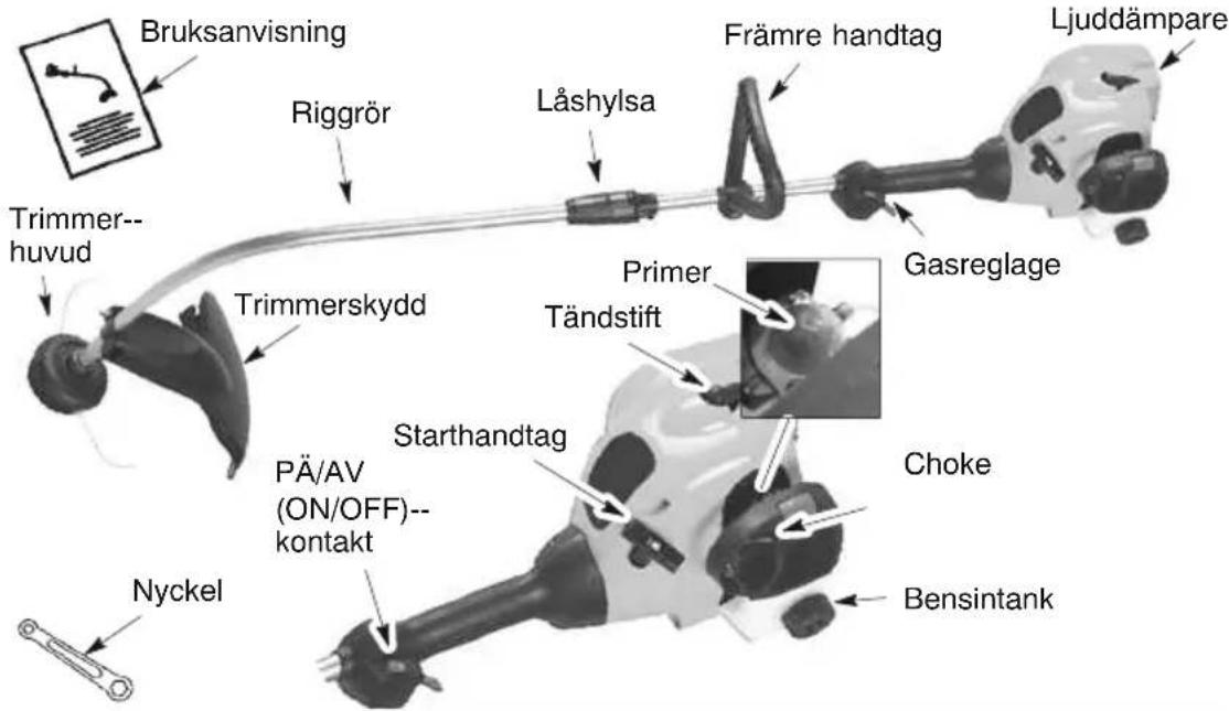
IDENTIFIERING (VAD ÅR VAD?)
FÖRKLARING AV SYMBOLER

A. VARNING! Denna trimmer kan vara farlig! Vardslos ell fer aktig anvandning kan orsaka allvarlig eller livshotande skada.
Anmalt organ for Maskiner (anmalt under 0197)
Tillystraße 2 - 90431 Nürnberg, Tyskland
MALLI:TRIMMAC(LT25NCOP)
MOOTTORI
VEDLIKEHOLDSSIKKERHET
SKIFT UT TENNPLUGGEN
INSTRUCTIONS DU FONCTIONNEMENT
POSITION LORS DE L'UTILISATION
ASSURANCE DE CONFORMITE
WAARSCHUWING: Zorg ervoor
DE HANDGREEP AFSTellen

WAARSCHUWING: Koppel de
CARBURATOR AFSTellen
WAARSCHUWING: Houd
WAARSCHUWING: Volbrengen
na elk gebruik:
SISTEMA DI ACCENSIONE
Candela'Champion
QCJ-6Y
REEMPLAZO DE LA BUJIA
Bujia Champion QCJ-6Y
Distancia de electrodos, mm 0,6
- Coloque as linhas nas ranhuras guia.
- Coloque a bobina na tampa.
ADVERTÉNCIA: Execute as
ZAL/WYL w poIozeni WYL.

paliwa)
WYSUWANIE SIEZYLIKII
vibratsionitased (R,eq), m/s
Originaalsevasak--/parempoolsemuruniidukipeaga 8,9/7,5
BHIMAHHE: Korato crIIO6BaTe Bana, noCTaBeTe ypeDa Bbpxy nIOCKa NOBbpxHOCT 3a CTa6NJHOCT.
- NopapabHete Xne6oBeTe Ha rOpHnI n DoJIHnBaJl.
- HaTnCHete Dbata BaJa eINH KbM dpyr, DOKaTO DoJHnRr HAnbJnHO BHe3e B RopHnra (BaNoBete 3aCTaBaT Ha MAcTo C UpaKaBaHe).
- ⅡIb3HeTe DoJHaTa ΦHKcnpaua BtUka BbpyrOpaTaΦHKcnpaua BtUka N 3aTeHHeTe Ype3 BbptHe No YacOBHNKOBaTa CTpeJIka.
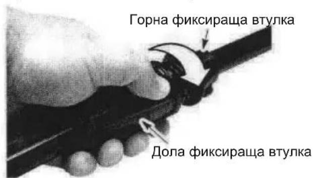
3A6EENKKA:AKOΦnKcnpaTaBtYlKaHe Ce 3aTeHRe,BAIOBeTe He ca HAnbNHO crNo6eHN eINH KbM dpyr.
PERYUNPAHE HA DPTbXkATA
BHIMAHHE! Korato perynnpate nomouhata dpbKka, BHIMaBaTe Ta da octaHe Haqikcupaata BtJka n noD MapknpoBkata nn CTpeKnata Bbpx BaJa.
-
Pa3xna6te KpuiuataTaraKaHa npbkkata.
-
3aBbPTeTe IpbXkata Bbpxy Bana Do n3npaBeHO nonoxeHne; 3aTeHete OTHOBO KpuiuHaTata raika.
MOHTIPAHE HA UNTA
BHIMAHHE! ⅢntbT Tp6Ba Da 6bJe npabnHIO MOHTnpaH. ⅢntbT OcnhypRa
yactuHa 3aunTa CpeuP nCK OT n3XBbPneH npeDMeTu KbM OepaTopa N dpyrN liua
n e cHa6dEn C orpaHnHTeH Ha KOpData, KOITO OTP3Ba n3NIuHaT a KopDa.
OrpaHnHTeJrT Ha KOpData (Ha DoJIHATA cTpaHa Ha uTa) e ocTbp N MoKe Da BV
nopexe.
- Cbane teraata ot ueta.
- NocTabete cko6a B npope3a Ha ueta.
- 3aBbPTeTe uHTa, DOKATO 6oNTbT BJe3E B OTBOP B CkObaTa.
- IocTabete OTHOBO raikata n 3aterhe Te 3paBO C raeueH KIOU (pnploxeh).
PABOTA
BHIMAHNE!прдда 3anoyhe,нелремнho npogete Инфорmaцята 3a ropIBOTOBpa3deHa npabnata 3a 6e3onacnoct.Ак He pa3bnpate npabnata 3a 6e3onacnoct,He ce onntBaIte da 3apeKdaTe ypeDa cn.OsbpHeTe ce KbM yIbJIHOMOueH cepBn3.
3APEKDAHE HA MOTOPAC TOPNBO
BHIMAHHE! Prn 3apeKdahe c ropuBO CBAJrTe KanaQKaTa 3a ropuBTO 6abHO. DBrarTep e ceptnФmupan 3a pa6oTa c 6e3OIOBEH 6eH3IN. PpeDu p60Ta 6eH3INbT Tp8Ba Da ce CMEcN C NOxODAIO KOJIueCTBO B3dUwHO OXJaDEHO MacNo 3a DByTAkTOB N BriratEn, PpeHa3NaYeHO 3a CMEcBaHe B CbOTHOseHne 50:1. CboTHoUSeHne 50:1 ce NoCTra qpe3 CMEcBaHeTo Ha 5 IITpa 6e3OIOBEH 6eH3IN C 0,1 IITpa MacNo. HE IV3I0J3BAITE MacNo 3a aBTOMoBnI IN MOTOpHnI. Te3N BIDOBe MACNO MORAT Da npuHrT NOBpeDa Ha MOTopa. Korato CMECBATE ropuBOTO, CpeDbaiTe IHCTpyKUnTE, O3NaueHbPxy KOHTeHepa Ha MacNoTo. CpeD kato Do6aBNTe MACNTO KbM 6eH3InHa, pa3KlAteTe KOHTeHepa, 3a da Ocnrypnte PbJHOTO CMEcBAHe Ha ropuBTO. BnHaR nPoouTaIte n Cna3BaIte npabnata 3a 6e3OAnchocT no OTHOseHne Ha ropuBTO, PpeDu Da 3apeDnTe ypeDa cn C ropuBO.
BHIMAHHE! HnKora He n3no3BaIte YnCT 6eH3nH 3a 3apeKdaHe Ha ypeHa. Toba ue npuHH NoCToHHN NOBpeDi Ha DnraTeJIa.
N3NCKBAHNA TROPBOTO
I3no3BaIte Do6pokaecTbeH 6e3oIOBeH 6eH3nH. Hau-HuCKOTOp npenopbHTeH0 OKtaHOBO YucNo e 90 (RON).
BAXHO
I3noJ3BaHeTo Ha rOpNBA, cMeceHn cbc cnInrT (NoBue oT 10% cnInrTHo cbDbpxaHne), MoKe Da npedn3Bvka npo6JIemn C pa6OtaT a n Cpoka Ha ekcnloaTaun Ha DBrVaTeJIa.
BHIMAHHE! HenpabHnHOTo n3no3BaHe Ha rOpBIO u/nn Cma3OuHm MaTePnAnI npedn3BnKbA np6bnem Kato: HenpabHnHO 3aJeNCTBaHe Ha cBeHNHTeJ, npeprBaHe, 3aNbpxHa He Hn3napEnH, 3ary6a Ha MOUHOCT, HeoCTaTbUHO OMcJIbaHe, pa3pyuBaHa He rOpBONPOBODITE, yNtBTHENrTa N BtpeWnHTe KOMNoHETn Ha Kap6ypaTopa n dp. Pn rOpBaTa, CbDbpxaun Cnpt, CMeCTa OT rOpBIO mACNO Norlbua MHOrO Bnara, KoETO BOIN DO OTdEJaHE Ha rOpBOTO OT MaclOTO.
KAKDA CINPATE YPEDA CN
3a da cnpeTe motopa, noctabe Te KInoua BKJ./N3KJI. B noIooJeHne I3KJI.
KAK DA CTAPTIPATE YPEDA CN
BHIMAHNE! PnBKnUOVAHe Ha MoTopa rnaBaTa Ha Kocaykata ige ce 3aBbptN.
136raBaTe DonnpaHe Do 3arnyuHnten. Pn ropeu, 3arnyuHnten MoKe da ce noJyat
cepno3Hn n3rapHn.
CTAPTIPAHE HA CTYIDH MOTOP (nIHa TOnbI MOTOp cIeD CBbpBaHe Ha rOpNBOTO
CTapTOBO noNoxehne
-
NocTabete ypeda Bbpxy paBHa nobbpxHOCT.
-
NocTaBeTe KJIoua BKJ./N3KJI.B noLoXeHne BKJI.
-
BaBHO HATnCHTe 6aJohUeTo 3a 3aJIbBaHe 6 nTn.
-
IpeMeCTeIocTHeTo 3a IpoCeJa Ha nIoXKeHne IIbJIeH IPOCEJI.
-
HatncheTe 3aDpBxTe HATnCHaT CnyCbKa, DOKATO n3nblHIne BCnKn OCTaHaJI N CTbNk.
-
IbpaTe BxkeTo 3a CTapTnpaHe p3KO, DOKaTO MOTOpBt N3daDe 3ByK KaTO Ye Jn ONITBa Da CTapTnpa, Ho He To IbpaTe NOBee O T 6 nTn.
-
BeDHara cIeI KaTo MOTOpbT n3daJe 3Byk, KaTo Ye JIn ONITBa Da CTapTnpa, IpeMeCTe IocTeTo Ha npocena Ha IIOJIOBnH DPOCEI.
8.ДьрайтБькeto3aCTapTupaHe p3ko,DOKATO MOTOpBt CTapTupa,HO He NOBeue ot 6 nbTu.AKO MOTOpBt He CTapTupa Cne6dpbNbaHn(BnoNoXeHne IIOOBnH DPOCEI),npeme cTeTe loCTyeTo HaDPocela Ha noNoXeHne IIbJIeH DPOCEI n HATncheTe 6aONOHceto 3a 3aJIINBaHne 6 nbTu.HaTncHeTe 3aApbXte cnycbKaHa ra3Ta n N3DbPnaTe BxKeto 3a CTapTupaHe OSe 2 nbTu.PpeMeCteTe NoCTyeTo Ha DPocela B noNoXeHne IIOOBnH DPOCEI n N3DbPnaTe BxKeto 3a CTapTupaHe,DOKATO MOTOpBt 3apa60Tu,HO He NOBeue OT 6 dpbNbaHn.
3A6EJEXKKA: Ako MOTOpbT He CTapTnpa, BepoTHo e 3aJaBeH. PpeMnHeTe KbM CTAPTIPAHE HA 3AIDABEH MOTOP.
- CnE Kato MOTOpBt CTapTnpa, octaBeTe Da npa6To 10 cekyHn, a Cne ToBa npemecTe Te NoCTyeTo Ha dpocela Ha N3KJIIOUey H DPOCEI (RUN). OcTaBeTe yepda Pa6To One 60 cekyHn Ha N3KJIIOUey H DPOCEI (RUN), npeDn da otyncHete cnycbKa Ha ra3Ta. 3AEBJEXKA: Ako MOTopBt Cnpe npri noLoxHeH He NoCTyeTo N3KJIIOUey H DPOCEI (RUN), npemecTe Te NoCTyeTo Ha dpocela Ha noLoxHeH NoIOBnH DPOCEI n 3dbpnaTe BbxKeTo, DokaTO MOTopBt 3apa6To, Ho He nobYeOT 6 nbTu.
CTAPTINPAHE HA TONbJI MOTOP
- NocTaBeTe KJIoua BKJ./I3KJI.B noLoXeHne BKJI.
- PpemecTeTe NoCTyeTo 3a Dpocena B noJIOXeHne IIOOBnH IPOCEJI.
- HATNCHETe 3aApbXte CnycbKa Ha ra3Ta. 3aApbXte CnycbKa Ha ra3Ta HATNCHaT DOKpaI, DOKaTO MOTOpBt 3apa6OTn IJaIKO.
4.ДьрайTe BxKeTo 3a CTapTnpaHe P83KO,ДOKATO MOTOpbT CTapTnpa, Ho He NOBueO15 n7n. - Octabete MOTopa da npabotn 15 ckyHn, a cneT TOBa npemecTe JIOCTeTo Ha IPOCEJa Ha N3KJIQUYEH IPOCEJ (RUN).
3A6EENKKA: Ako MOTOpBT He CTapTnpa, DpbNHHe Te BxKeTo 3a CTapTnpaHe Oue 5 nTbTu. Ako MOTOpBT BCE OSe He paBoto, ToB BePOrTHo e 3aDaBeH.
CTAPTIPAHE HA 3AADABEH MOTOP
3aDaBeHnTe MOTOpn MoRaT Da Ce CTapTnpa, KaTo Ce NocTaBn JIOCTYeTO 3a DpoCeJa B noLoXeHne IV3KIIIOUeyEN DIPOCEI (RUN); cNei ToBa dpbHnTe BbxKeTo, 3a da IpoOuNCTHTe MOTopa OT n3nHOTo rOpBO.ToBa MOxE Da n3nCKBa MHOrO dpbNBAHn Ha dPbXkata 3a CTapTnpaHe, B 3aBncMOCt OT CTeneHTa Ha 3aDaBnHe Ha ypeHa. Ako MOTopbT BCE oSe He ce CTapTnpa, Bk. TAbJIuCATA 3A OTCTPAHRAHE HA HEIN3NPABHOCTN.
INHCTPYKUIN 3A PABOTA PABOTHO NOJIOXEHNE
BHIMAHHE! BuHaH HoCeTe NoXoJaU npEJa3nteHa OuTe n Clyxa. Hnkora He ce 6bIraIte BbPxy rnaBata Ha KocaykaTa. KaMbH nn OTnAbu MoKe da pIKOswipaT B OHTe N IuTeTo BN N da PpeDn3BnKaT OCnEJaBaHe nn DpyrO cepno3Ho HapaHbAhe.
He nyskaTe MOTopa npn no-Bucoka ckopocT, OTKoJkoTo e Heo6xOdmo. Pexeata Koprda ige pexe eefekTINBHO, KOrato MOTOpbT pa6OT npn o60pOn, NO-HnCKN OT nbJHa ra3. Ppr no-Hnckn o60pOt nMa n no-MaIkn OWM n Bn6paun Ha MOTopa. Pexeata
Kopda Ie Tpae No-DbIro BpeMe n C no-Manka BepoarTHoc Tce Ce "3abapu" Bbpxy Makapata.
BnHaHOr OtnyckaIte CnycbKa Ha r3Ta, 3a da ocTabInTe MoTopa Da ce BbpHe Ha obOpOTn Ha npa3eH xoI, Korato He pexkete.
3a da cnpeTe MoTopa:
OtnycheTe cnycbKa Ha ra3Ta.
IocTaBeTe KInOua BKJ./N3KJI. B noNoXeHne I3KJI.
N3JIIN3AHE HA KOPDA HA KOCAYKATA
KopdaTHa KocaykaTa ige n3n3a c np6n3nteJHO 5 cm BCEKNbT, KORAto DoJHata
act Ha rnaBata Ha Kocaykata ce yukHe B 3emrTa, npMOTOp, pa6oteu Ha nbHa ra3.
Ha-eFikacHaTa DblxHa Ha KopdaTa e MaKcImaHaTa DblxHa, N03BOJBaHa OT
OrpaHnHTeJa Ha KopdaTa. BuHa rnoDlbpxaIte uNTa NoCTaBeH ha MAcTo, KORAto
pa6oTnte C ypeDa.
BHIMAHNE! I3noI3BaIte cAmO KOpda C dIaMeTbp 2 MM. PnDpyrpa3Mepn I φopmHa KOpTa TЯ HMa Da I3JIN3a npabNtHO N TOBa Ue DoBede Do He npabNtHa ΦyHKUHa Ha p3aHe Ha rIaBata, KoETo MoKe Da npuHnC cepNo3HO HapaHbAhe. He I3noI3BaIte Dpyr MaTePnaJI NaTO XNu, KOHeU, BxKe U dp. XNuTa MoKe da Ce OTyInn pRn p3aHe n Da ce npEBpHe B ONaCHA paKeTa, KOrTo Da npuHnC cepNo3HO HapaHbAhe.
METODI HA PRA3AHE
BHIMAHNE!ИЗнOL3ВаTe MInHMaJIHa CkOPOCTи HeДONyCKaIe HATpyNBAHe Ha KOPda, KOratopeXeTe OKOIO TBbPdI npeDMETn (KaMbHn, YaKbI, KOLOBE Ha ORpda N Dp.), KOnTO MoXe Da IOBpeJr TlAbTa Ha KocauKaTa, Da ce 3AnJeTb KOpdaTa IIN Da Ce INxBbPJIr, KoTo Da c63JaIe cepNo3Ha OnaCHOCT.
PraheTo ce n3Bpwa ot kpa Ha KopdaTa. Ie noctnHte Ha-no6pa eKTHBOCT mHmMaJIHO n3HOCBaHe Ha KopdaTa, aKO He HATpyNBATE KOPDa B 30HaTa Ha p3aHe. Io-dony ca nokaAH npabuHnT n rpeuHnT haun.
KocheTo Ce n3BbPwBa OT KpaHa KopdaTa.
KopdaTa e ha6paHa B pa60ThaTa 06JaCT.
KopdaTae Iecno ige npemaxBa TpeBa n PnBeBn OkOIO CTeHn, OrpaDN, DbPBeTa n CBeTHn IexN, HO MoKe Da pExe N BnCraIa Kopa OTo DbPBeTa UIn Xpactanak N da Oueptaba OrpaDN.
3a noDpr3BaHe nInn 3TpBΓBaHe, n3NoI3BaIe No-HnCKn O6OpOTn OT nbHata ra3, 3a da yNbJNKeTe XnBOTa Ha KOpDaTa NHaMaJInte n3HOCBaHETo Ha rnaBATA, oco6eHo:
-Повреман рязанпи пк ржим.
-B 6n30ct do oBeKTH, OKoNo KOnTo KOpDaTa MoKe Da ce ycye, HapPmep TbHKn KOJOBe, DbPbEta nn OrpaHa TeJ.
3a Kocene nIIN npOuHCTBaHe n3nON3BaIe TbIHa ra3, 3a Do6pa N uCtTa pa60Ta.
IOPR3BAHE -ДрькTe ДолнаТа уст Ha ГлаваТа Ha KocaykaTа Ha OKOJI 8 CM HaJ3emЯТи NOД bгЛ. OctabeTe KOtakTbT Da ce N3BbPwBa cmo C kpar Ha KopdaTa. HeHATNCKaIte cbc cnla KOpdAra B 30HaTа Ha pa6Ota.
N3TPbΓBAHE - IoxBaTbT Ha n3TpBΓBaHe cnyxn 3a OTcTaPraHbAHe Ha HeHyxHa pactnteHocT. DpbXte Donhata Yact Ha rnaBata Ha Kocaykata Ha OKONo 8cm Hnd 3emrTa n noD bIbn. OctabeTe KpaT Ha KopdaT da ce ypr B 3emrTa OKONO dIpbEta, KOIOBE, OCHOBn n dp. To3n noxBat yBeJIuYaba n3HOCBaHeto Ha Kopdata.
N3TPbΓBAHE
KOCEHE - Baawata Kocayka e nideaHa 3a KOceHe Ha MeCTa, KOHTO cTaNapTHnTe TpeBn KocayKn He Morat Da DoCTnAT. B noLoXeHne 3a KOceHe, DpbXte KopDaTa ycnopeHa Ha 3emrTa. N36raBaiTe Da HATnCKate rnaBaTa B 3emrTa, TbN KaTO TOBa MoKe Ja n3TpBrHe 3emrN da NobpeDn IHCTpyMeHTa.
KOCEHE
ПОЧNTBAHE - BeHTnIaTOPHOTO DeIcTBHe Ha BbPTaTa ce KOpda MoKe da ce n3noI3Ba 3a 6bp30и IeCHO YIcTeHe.ДрБxTe KOpdA ta NapaIeHa Ha NHa nOBbpxHOCTte, KOINTo Ce IpoUcTbAT, И DBNXeTe INHcTpymEHTa OT eDHaTa Ha dpyrata CTpaHa.
ПОЧИСТВАЕ
TEXHnuecko OBCJIyKBAHE
BHIMAHNE! IpeKbcHeTe Bpb3KaTa KbM CBeUta npeNi TexHnuecko O6cnykBaHe, OCBeH npi HacTpoKn Ha Kap6ypaTopa.
ПЮВЕРЕТЕ 3A PA3XЛАБЕНФИКCATOPИЧАCTИ
-KoH3OJa Ha CBeuTa
Bb3dyueHΦnIITbp
BUNTOBE Ha KOxya
BnHT Ha nOMOHaTa dpbXka
·Ⅲnt3aOTnabun
ПЮВЕРЕТЕ 3A NOBPEDEH NЛN N3HOCEH YACTN
OsbpHeTe ce KbM yNbHOMOeH cepBn3 3a 3amHa Ha NOBpeHnte NIN N3HOceHn Yactn.
Knou BKJ./N3KJI. - YBepTe ce, ye KIOUbT BKJ./N3KJI. e n3npaBeH, KaTo ro noCTabte B noLoXeHne N3KJI. YBepTe ce, ye MOTOpbTe cnpra; cIeD TOBa ro npChete OTHOBO n npOdbJIxkeTe.
Pe3epBoap 3a rOpB0 - CnpTe da n3no3BaTe ypeDa, ako pe3epBoapbT 3a rOpB0 nokaxe npn3Haun Ha nobpeDa nn npOTnuAhe.
IHT3aOTnabun-Cnpete da n3noJ3BaTe ypeDa,ako uNTbT 3a OTnadBuH e NOBpeDeH.
ПОВЕРETЕ И NOΥСТETE UРEDA И ETИКETITE
CneB BcKa ynoTpe6a npOBepBaIte ypeDa 3a pa3Xna6eHn nn nobpeDeHn qactn. Pocntete ypeDa n eTKeTHe, KaTo n3non3BaTe BnaKHa KbpNa CbC cna6 MnaJeH npenapat.
I36bpoTe ypea c ucta cyxa Kbpna.
NOUCTBAHE HA Bb3dYuHHNФHJTbP
3ambpceHnT Bb3dyuWeH cHNTbP BNOaBa pa6oTaHa MoToPa n yBeNnAba KOHCymaunrTa Ha rOpBnOB n BpeHNTe emncnn. BuHaRn nouchBaIte cJeD BCEK 5 Yaca pa6ota.
- NocntBaIte Kanaka I MCTOTO OKOIO Hero, 3a Da He No3BONITE KaI da nonaHe B Kamepata Ha Kap6ypatopa, Korato 6bDe CBAeH KanakBT.
- Yactnte ce CBAJRT, KaKTo e NIOCTpnpaHO.
3A6EJEXKKA: He nouCTBaIte qnITbpa B 6eH3nH nIN dpyR Bb3nAmEH m pa3TBOpHTen, 3a da n36erHeTe pNcKa OT NOXAP anACHn n3napEnia.
- PpomnTe pntbpa cbc canyH BOda.
- OctaBeTe fHJTbpa Da n3cbxHe.
- DobaBete HAKOJIKO KANKIN MACNO BbB FNTbpa; CTNCHeTe FNTbpa, 3a da pa3npedeJNTe MacNoto.
- NocTabete Ha MRCTo Yactnte.
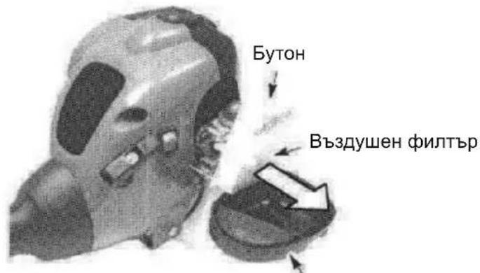
Kanak Ha Bb3dyuHnA qntTbp
CMRAHACBELTA
CBeuTa Tp6Ba Da ce CMeHb BcKa rOHa, 3a Da ce rapaHTnpa, Ye MOTOpbT ue ce cctapTnpa no-Necho H uce pa6oTn no-do6pe. PerynpaTe MeKdHaTa MeKdy KOHTaKTtHe Ha CBeuTa Ha 0,6 MM. BpeMeTo Ha 3anaIbaHe e qHKCuPaHO n He MoKe da ce perynpa.
- 3aBbptete, a cneToba n3BaTe TE KOH3OJaTa Ha CBeuTa.
- 13BaTe CBeUta OuINHbpa Iy NxBbpeTe.
- 3aMeHeTe r cBc CBeu ChampionQCJ-6Y n a 3aTerHeTe 3dpaBO c rnyx KIOU 19 MM.
- IocTabete Ha Mxcto KOH3OJaTa Ha CBeuTa.
CEPBn3 IN PEGYINPOBKN CMHA HA KOPDATA
- HatncheTe fKcTopuTe OCTpaHn Ha rnaBata 3a p3aHe n cBaJeTe Kanaka makapata.
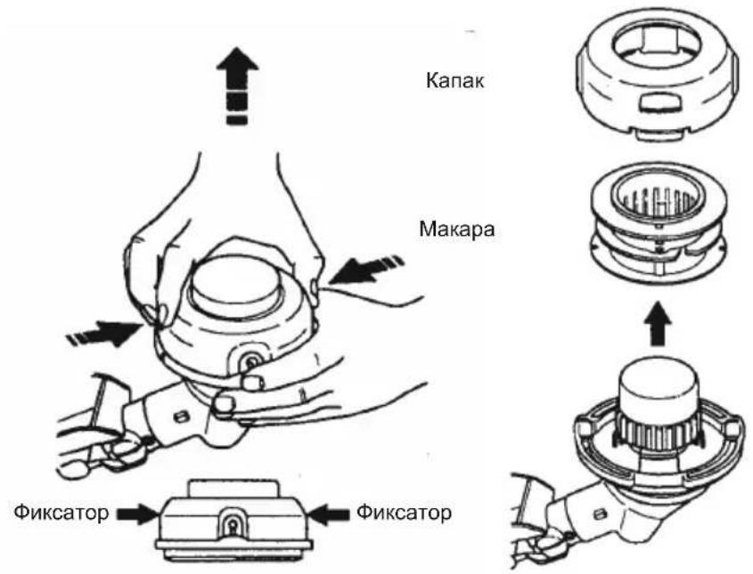
2.ИЗвадаTe OCTaBaUaTa KOpda.
3. IOnuHCTe 3aMbpcBaHnra TIOCTaTbUHTe OT BCNUqYactN. 3ameHete MaKapata, aKO e N3HOceHa INI NOBpeDeHa.
4. 3aMeHete r c npEeBapntEnHO HaMOTaHa MaKapa, KaTo n3nOJ3BaTe IbJnxHa OKoJIO 4,5 MeTpa C dNaMeTbp 2,4 MM.
5. Korato noctabrTe HOBa KOpDa Bbpy CbueCTByBaUa MaKapa, DpbjTe MaKapaTa, KaKTo e NOKa3aHo Ha fNrgpata No-dony.
6. IperbHete KOpda Ta B CpeaTa N BmBkHeTe IperbBkata B npope3a B cHTpaHaTa paMaHa MaKapata.YBepTe ce, Ye KOpdaTa e ippaKaHaJa Ha MRCTo B npope3a.
- Kato noctabnte npbct Mejky HABNBNTe Ha KopdaT, Ra HABNte paBHomepHO OKJIO MAKapata B NOCOKa Ha YacOBHKOBATA CTpeJIka.
- NocTabaTe HABNVbKNTe Ha KOpdaTbBb BOneUte npope3n.
- NocTabete Makapata B kanaka
- Ппекаши Краида Та Н Кордота пез ИЗхODЯЦNTe OTBOPИВ CTpaHINHTe CTEHИНКANAKA.
OTbOpn 3a n3m3aHe Ha KopdaTa

- NocTabete OTHOBOMakapata n Kanaka Bbpxy rnaBata 3a p3aHe. HATNCHTe, DOKATO KANAKBT UpaKHe Ha MCTO.
PEYUNPAHE HA KAPBYPATOPA
BHIMAHNE! He donyckaite B 6n3ocdpyx xopa, KORATo npaBte perynnpOBKITE Ha npa3nXoJ. No BpeMe Ha ta3n npoeDypa rnaBata Ha Kocaykata ue ce BbptN. Hocete 3aunTHnte cncpeCTBa n cb6nOdaBte BCNUK MEPK 3a 6e3OnacHOCT.
Kap6ypatopbTe BHNMaTeJIHO HAcTpoEH 3aOJa. PeryInpOBKn MoKe da 6bDat Heo6xOIMN, aKO 3a6eJekTe Bb3HnKbaHeTo Ha HraKoe OT CneDHnTe yCNOBn:
MToOpbT Hma Da pa6oTu Ha npa3eH XoI, KOrato ra3Ta ce OTnycHe. HanpaBetepe rpynnpOBKeTe, KaTo NpOdbpKaTe ypeDa No TaKbHaunH, Ye pepeTo npncnoc6neHne e HAd ZemrTa n Hma Da ce Donpe Do HkaKbN ppeMet. PpiDbPkaTe ypeDa c pbKa, DOKato pa6oTuE n npabTe peynpOBKn. Pa3eTe BCnKu Yactn Ha TAnoto Cn daJeUOT pekeTo npncnoc6neHne u 3arnyuInTeIa.
PerynpoBka Ha npa3Hna XoJ
IpycheTe MToTaHa npa3eH xoJ. PerynnpaTte 6opOTte,doKATO MOTOpbT pa60Tu 6e3 npekcbAHe (pni npa3eH xoD CTbPde Hnckn o6opOTn).
3aBbptete BNHTa 3a ckopocT ha npa3eH xoI no yacOBHKOBaTa cTpelenka, 3a da yBeNnTe o6OpOTte Ha MOTopa, aKO npeKcbNA HIN 3araCBA.
3aBbptete BnHTa 3a CKOpOCT Ha npa3eH XoJ o6paTHo Ha YacOBHnKOBaTa CTePknKa, 3a Da HamaNTe O6opOTnte.
3A6EENKKA:ПиИЗNON3BaHHe Ha roPnBTo Aspen 2T, yckopeHneTo Ha DBnraTeN MoKeJa 6bJe no-6aBHo.
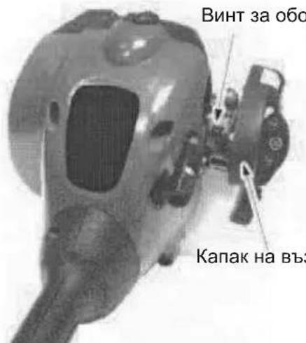
BnHT 3a o6opOTn Ha npa3eH xoD
KanakHaBb3DyHnHnФnTbp
AkoBn e Heo6xoDm aOnbHnTeHa NOMOu nHe cTe yBepeHn B n3nbHeHneTo Ha Ta3n npoueDpya, ce 06bphEt Ke bHnHomOueh cepBu3.
CbXPAHEHNE
BHIMAHHE! CneB BcraKa ynoTpe6a n3nBJIHbAaTe CneHNTE CTbNkI:
OCTaBete DnIraTeTna I3CTnHe, npei Da ro npnbepeHa cbxpaHHe nnn TpaHCnOpTpNaTe.
CbxpaHbAte ypea n rOpBTo Ha do6pe npoBetpBaHo MxCTO,Ha KOeT O napTe Ha rOpBOTO da He MORAT Da DOCTnHaT Do NCKPN NIN OTKpNT NAmbk OT HArpeBaTeJn HA BOda, eNEkTpOMOTOp NIN PBeKBIOUBAteJN, Neu n dp.
I3npa3HeTe pe3epBoapa 3a roPBO, npEn da npnbepeHa cxbxpaHne nn TpaHCnOpTpate ypea.
CbxpaHbAte ypea n ropnbTO daJeu ot o6cera Ha deca.
CbxpaHbAte ypea c BcNk npedna3nIeIIOCTabeH. NocTabeTe ypea H TAKOBA MRCTO, Ye HeROBa OCTpa YacT Da He MOKe da PpUHHN CNYaHHO HapaHbAHe.
CE3OHHO CbXPAHEHME
IoproTBeTe ypea 3a cbxpaHHe cnei 3aBbPbBaHe Ha ce30Ha nIaKO ToI HMa da ce n3non3Ba 30 dHi nn noBeYe.
Ako ypeBbT Bn Tp8Ba Da ce npnbepe Ha cbxpaHHe 3a onpeJeH cpoK:
Ppei npoBjnxTeHcxbxpaHHeHne nouchte Te cIyra ype.
CbXpaHbAaTe ypeHa Na uCTO n cyxo Macto.
KeHaMaXeTe C MacNo BbHUnHe MeTaHn NOBpbxHOCTN.
MOTOP
I3BaTe CBeUa HaneIe 1 yaeHa IbXnUka MacNo 3a DByTaKToB DBrIaTeN 3a CmecBaHe 50:1 B OTbopa Ha CBeUta. DpbHHeTe 6abHO BxKeTo 3a CTapTnpaHe 8 do 10 nbTN, 3a da pa3npedeJIte MacNOto.
3ameheTe CBeuTa C HOba OT npenopbUbaHn TUN n TOJINHeH dnaana3OH.
- Nounctete Bb3dyuHHnqunTbp.
IpoBepete cenya ype3a pa3xnaabeHH BnHTOBe,raKu n 6oTObE.3ameHete BCNUKNIOBpeDeHN,CyneHH NnN 3HOceHH Yactn.
Ipn 3anoUbaHe Ha CneBaunCe3OH, H3noN3BaTe cMo HOBO rOpNB0, C Heo6xOJMMOTcBtHOJHHe Ha 6eH3nH MaCNO.
ДPyГИ
He cbxpaHbAaTe 6eH3nH OT eINH ce3OH 3a dpyr.
3aMeHete Ty6aTa 3a 6eH3nH, aKo 3aNoUHe da pJxJaCBA.
TABJIUCA 3A OTCTPAHRAHE HA HEN3INPABHOCTN
BHIMAHHE! BuHaH cnnpaIte ypeDa n ppeKbCBAIte Bpb3KaTa KbM CBeU Ta, ppei Da n3nBnHraBe I npenOpbYBaHIne KopeKcun No-dOly, c N3KnIOueHHe Ha KopeKcUnTe, KOITOn n3NCKBaT ypeBt da pa6OTn.
2006/42/EO no OTHoWeHHe Ha MaunHHTo o6OpyDbAhe (2006-05-17)
2014/30/EC no OTHoUeHHe Ha eNeKtpomarHHTHaTa CbBMeCTMIOCT (2014-02-26)
2000/14/EO NO OTHOWeHHe Ha eMUCnTe Ha 7yM B OkOnHaTa cpeJa (2000-05-08)
B CbOTBcTCTBnC AHeKc V, DeKlapnpaHnTe CToHocTn Ha 7ym Ca NocOueHN B JInCTa C TexHnueChn DaHHn Ha pBkoBDCTBOTo 3a onepaTopa.
Pnntaratge GntaHnTgAaptn:
EN ISO 12100:2010, EN ISO 11806-1:2011, CISPR 12:2007, ISO 14982:2009
TUV Rheinland LGA Products GmbH
IocoueHO BeDMCTBO 3a MaunHHOTo o6OpyBaHe (nocoueHO nD 0197)
Tillystraße 2 - 90431 Nürnberg, Germany
TUV Rheinland N.A. npoBepe ueeneHacOeHO nHTBaHe Ha TnHa OT HMeTo Ha Husqvarna AB, KaTO
IpeIOCTaBn AIGP3HHT 3a H3NITBaHe Ha TIna. To3n cepTnΦHKat 3a ueJeHaocOeHO
H3NTBAHe e npilokm 3a BCnK MeCTa Ha npOn3BOcTBo n CTpaHn Ha npOn3XoD, KaKTo e NocOeHO Ha npOdykTa. OoctabeHnT TpImep H/nn Xpactope3auchKa OTROBapra Ha npImepHnmaOdeJ, KoTo e npemHaI npE3 EBponeNcKO H3NTBAHe Ha Tnna.
IopnncanoOT HmTo Ha: Husqvarna AB, Huskvarna, Sweden, 01-10-2013

Ronnie E. Goldman, Director of Engineering (YpbHOMOeH npedCTaBHTeN oTRObApu 3a TeXnueckata DOKymeHTaun)
MOJEL:TRIMMAC(LT25NCOP)
MOTOP
Pa6oTeH o6eM, cm³ 25
PnMaKcMaJHa MoHocT Ha DBrTaTeJIa, 06./MnH. 8000
MaKcImaJIHa YecToTa Ha BbPteHe Ha OCTa, 06./MnH. 10000
CkopoCT Ha DnBiratJIpy npnpenOpbYBaHm MaKcMaJHn
obopOTn Ha BbptHe Ha octa, o6./MnH. 10000
IpenopbUbaHn o6oTn Ha npa3eH xoD, o6./MmH. 4000
MaKcMajHa MoiHCT Ha DnBraTeIa, I3MepeHa B CbOTBeTCTBne c ISO 8893, KW 0,6
KaTaNITUeH KOHBePTOpEn 3aIyuINTeI Da
CNCTEMA HA 3ANAJBAHE
Cbeu Champion
Pa3cToHnE MeKdy eJekTpoDnte,MM 0,6
TOPUBO IN CMA3OUHA CNTEMA
BmectnmoctHa pe3epBoapa 3a ropno, cm3 340
Pa3xOHa ro npu MaKcImaHb MoHocT Ha DnIraTeJn,
n3Mepeh B cboTBetCTBne c ISO 8893,g/h 407
CneuPhiupan pa3xoHa ro npu MaKcImaHa MoHocT
Ha DnIraTeJn, n3Mepeh B cbOTBeTCTBne c ISO 8893,g/kWh 768
TEIIO
Be3 npncno6leHne 3a p3aHe nn nT, npa3eH pe3epBoap, kg 3,9
EMUCN HA WYM
(Bx.3a6eJexka1) HnBOHa 3ByKoBaTa MoHocT, n3MepeHa dB(A) 109 HnBOHa 3ByKoBaTa MoHocT, rapaHTnpaHa LwA, dB(A) 115
HMBA HA 3BYKA
(Bx. 3a6eJekka 2)
EKBVAJIeHTH HbHa Ha 3ByKOBOTo HAJrAHe npu yxOTo Ha
noTpe6nteIy, n3MepeHn B cBoTBcTCTBne c EN ISO 11806 n
ISO 22868,dB(A)
ObopydBaH c TpImeRHa rnaBa (opuHaJIHa) 100
HNBHA BNBPAUNITE
(BK. 3a6eNeKka 3)
EKBBaJIeHTHn HbHa Na Bn6paIaTa (ahv,eq) B pBkoXBaTKITE,
m3MepeHcBrlacHo EN ISO 11806 n ISO 22867, m/s2
O6OpuDbAH cTpImepHa rIaBa (opRInHaIIHa), IraBO/daCHO 8,9/7,5
3a6eJekka 1: EmcHnTe Ha Wyma B OKJHaTa CpeJa, n3MepeHn KaTo 3ByKObAMoHocT (LwA) B cbOTBeTCTBne C dIpeKtNbHa ha EO 2000/14/EO. OTYeTeHnTe HnBa HaWyma 3a MaunHaTa ca n3MepeHn C oprHnHaJIHO tpeKeIoo o6OpyDbaHe, KoEtO daBaHaN-BnCOKOTO HnBO. Pa3NJkata MeJy rapaHTnpaHOTo N n3MepeHOTo HnBO Ha Wyma e BTOBa, Ye rapaHTnpaHOTo HnBO Ha Wyma BKIIIOUvBa CbIoo I DCnepCnraTa B pe3yIITaNTeOT n3MepBaHTo, KAKTO IN BapnaCnTE MExJy pa3JIuHnTe MaUnHn OT eINH INCbUIMoJeI, B cbOTBeTCTBne C dIpeKtNbA 2000/14/EC.
3a6eJekka 2: OTuTeHnTe DaHHN 3a EKBuBaJIeHTHO To HnBO Ha 3ByKOBOTo HaJIraHe 3a MaunHaT aMAt TnUuHa CTaTnCTnuecka DnCnepcna (CTaHdapTHO OTKnOHeHne) ot 1 dB(A).
3a6eJekka 3: OTuTeHInTe DaHHN 3a EKBuBaJIeHTHO paBHNue Ha Bn6paUra Ta IMaTINnHa cTaTnCTnuecka dncnepcna (CTaHdapTHO OTKNoHeHne) ot 1m / s^2
BE3ONACHOCTb ONEPATOPA NPEyPExKDeHHe:MaunHa Bo
pa60tbi CO3daet 3JNEKTPomarHHTHOe noJe. B
ONpeDeIeHHbIX O6CTOReTbCTBax 3TO NOle
MOKeTe CO3DaBaTB NOMExn IJI NaCCNBbIX N
AKTHBbIX MeINHCKNX IMNlaHTaHTOB.
YTo6bl N36exKaTb PnCKa cepBe3HOrO
NOBpeKdEHNr INn CMePTN, JInzam C
MeINuHckmN ImNlaHTaHTAmN
peKOMeHdyETc npOKoHCyNbTIpOBAbCra C
BpaQOM IN3ROTOBHTeMe IMNpaHTaTa,
npexde Yem pncTyNaTb K pa6ote c 3Toi
MaunHoH.
OeBaITeCb COOTBETCTBYUIM O6pa3OM. Pn 3KcNpy aTaun nInn 06CnykubAHn BAweo yCTpoiCTBa NcNoJIb3yIte 3aUNTHbIE OUYIN DpyrIe NOIO6HbIE 3aUNTHbIE CpeCDTBA. 3aUNTHbIE OOKI DOJIKHbI IMeTb MapKnPOBky Z87.
- Pn pa6oTe B 3aBileHHbIX MecTx Bcerda HadeBaIeMaCKy IJIa NIIa MACKy OT IIJI.
Bcerda haedeBaIte nIOTHbIE dINHHbIe UTaHbI, py6aKc y dINHHbIMn pyKaBaAMn, 60tNHKn n nepuATKn. PeKOMeHdyETc HaeBaTb 3aunTHbIe cpeCTBa Ira Hor.
Bcerda Hocnte 3aunthyO oByb. He xoJnte 60cNKOM n He HOCnte caHaJIIN. PacnoJaaraTecb Ha pacCToHnN OT BpaauuuxcI detaJe yctpoCTBa.
3aKoJInte BOIOcbl,ecn OHIOCTAOT Do nIeU. 3aKpeINTE NnCHIMNTe CBO6OHyO OExkdy Nn ODeXkyC He 3acteryHM MaHKeTAMn,CHe 3aB3aHHbIMN JIeHTAMn T.n.Cbo6OHaN Hn He 3acteryo OExKa MoXeT NonActb B DnKyUneCe qACTn MEXaHN3Ma YcTPOJCTBa.
-ПолнаяЗациТЯ NOВЕРХHOCTNTeNA TAKKE NO3BOJNT Bam ybepeYbcr OТ MYCOPA N OCTaTKOB TOKCNUHbIX paCTeHn, OT6pacbIbAeMbIx rA3OHOKOcNkoI.
- BybTe BcERda BHIMATEbHbI. He NOlb3yntecb yCTPOBCTBOM, ecIN Bbl yCTaNN, 60JIbHbI INN YEM-TO paccTpoehbI, INN ecIN Bbl HAXOINTeCb NOB3deJCTBnEM anKORoJ NIN KAKNX-JIN6O JekapCTBeHHbIX npenapatOB. CneDNTe 3a TEM, yTO Bbl Denaete, OyNbTe pa3ymHbI.
BoBpempa60tblnna3aunTbyuwe nCnoJb3ynte6epyuin.
InyuHTeN C kataJn3aTOpam B npoecce pa60tBcJbHO HarpeBaIoTcN HeKOTOpoe Bpem Nocne BblKnIOueHnO ctaIOCTc RopAHHN.3TO npONCXoINr HxOIOCTOM XOy. PnIKoCHOBHeN K Hm MOXET pInBecTN K OXOry KOxN. POMHNT 6 onaCHOCTN BO3HNKHOBEHn noXapa!
- HNKoIgHa He 3anyckaIte DnBraTeIb n He daBaIte emy pa6OtaB B 3akpyITOM nOMEueHnn nn 3daHnn. BdbixaHne BbIXIOINbIX raoB MoXeT npNBecTn K CmeptJIbHOMy NCxOy.
He donyckaTe nonaHaTHnToJIbMa macna Ha pyuKny cTpoNCTBa.
TEXHnKA B63ONACHOCTN INPN 3KcJIyATAUINI
OBCJNYKUBAHUYCTPOICTBA
Bce DeiCTBnno 06nyKBAHnIO,3a NCKNHOeHNEM HAcTPOIKn KAp6IopAToPA, DOJXHBblINHrTBcR npn OTcoEINHeHHo CBeue 3aKnraHn.
- Ppeq KaJbIM nCNoIb3OBAHnEm OCMOTpTe yCTpoNCTBO Ha HAnuHe NOBpeKdEHHbIX NIN OTBePHyBuxxCr DeTanei 3aMeHnte nx. Ppeq nCNoIb3OBAHnEm OCMOTpTe yCTpoNCTBa Ha HAnuYe yTeuek TOnJIbNA u yCTpaHnTe nx. CoepKnte yCTpoNCTBO B xopoWem pa6oYem COCTOHN.
- Ppei nCIOJIb3OBAHnEM yCTPOIcTBA 3aMeHInTe De TaIN CTPNHyueI rONOBK, ecJIN OHN IMeHT CKONbl, TpeUHHbl, CJOMAHBI ININ IOBpeXKeHbI TEM ININ HbIM o6pa30M.
BbINOHnTe 06cnyKuBaHne yCTpoNCTBa B COOTBETCTBUN C peKOMeHdyEmbIMn npoceDypAMn. DepxNte CTpyUyuroOBky Ha COOTBETCTBYIOUcEM paCCTOHN.
-Дяpe3kn nCnoJb3yIte TOnko peKyo cTpyHy dIaMeTpOM 2 MM. He nCnoJb3yIte npoBoDa,BepeBKn,CTpyHbI N.T.I.
- Pered nCNoJIb3OBAHnEM yCTpoIcTBA npabNtBHO yCTaHOBnTe 3aunTHbI kKpaH. NcnoJIb3yIne ToNbKO yKa3aHHyo cTpiRyuTo rOIOBky; y6eDntEcB, YTO OHa npabNtBHO yCTaHOBJeHa n HaDeXHo 3akpenHeHa.
- Y6eIntecb B IpaBnIbHOCHTN C60pKN yCTPOnCTBa B COOTBeTCTBIM C daHHbIM pyKOBODTBOM.
PerynpoBky Kap6bopaTopa npOn3BODnte c noDnTOn HxKHe yAcTbIO, YTO6bl CTpyuza rOIOBka He KacaJaCb HnKaKOro npedMeTa.
- Ppi perynipOBKe Kapbiopatopa, noCTOpOHHe DOJXHbI HAXOHTbcr Ha 6e3onachom pacctoHn.
IcnoIb3yIe ToIbKO npHaIeXHocTn 3aIacHbIe YactN, KOtOpblpeKOMeHdyEmble.
Bce 6cnykBaHne n peMOHT yCTpOINCTBa, KOToPbIe He yKa3aHbI B DaHHOM pyKOBOIDCTBE, DOJXHBbl BblONHrTbcra aBTOPi3OBaHHbIM DnJIpeom P0 6cnykBaHHIO.
MEPbI INPEAOCTOPOXHOCTN INPNOBPAUHNC TOJIINBOM
CmeunBaIe n 3aunBaIte TOnnBO BHe NOMeueHn.
XpaHnTe TOnJIINBO BdaJN OT MeCT o6pa3OBAHN ICKP NIIOTKpbITORO nJaMeHn.
- NcnoJb3yIe EMKoCTN, CNEuaJIbHO npedHa3NaueHHbe DnTOnJIbBa.
He Kypnte Hne DonyckaIte KypeHnpaDM C TOINBOM INC yCTpoiCTBOM.
He npolnBaIe TOnJIuBO nIM MacNo. BbITPte BCE pa3NHBueecr TOnJIuBO
- Перед зауckом Двигатултесь, Кам минимун, на 3metpa OT моста заразыкп ТОПЛВОМ.
- Pered OTKpbIHTeM TOnnBHO np6Kn BbIKJIOUHTe DnurTaTeJIb n daITe emy OCTbITb.
Bcerda xpaHnTe TOnJIuBO B EMKoCTx, CneuaanbHo npeHa3HaueHHbIX DnRA BOcIIaMeHraIOUxxCs KJDKOCTe.
TEXHnKA B63ONACHOCTN IPN PE3KE TPABbl
PNEpyPEXKDEHNE:peepKaJdbIM nCNoIb3OBAHnEM yCTpoiCTBa,OCMOTpnte TepprTOpHIO.YaJIInTe HnOpOHNbe npEdMeTb (kAMHI,CTeKnA, rBO3Dn, npOBoA u T.n.), KOTOpBle MOrYT 6bITb OTbPOWeHb ra3OHOKoNko ININ MOrYT nonAcTb B CTpyuOIO roNOBky. TJeKeIbe npEdMeTb MOry NOpeDnTB CTpyuOIO roNOBky ININ 6bITb OTbPOWeHb,ITO MoKET pINBeCTN K TpaBMe.
IcnoJb3yIte DaHHoe yCTpoiCTO JToJIbKO IJRA CTpIXKKn, YdaJIeHnPAcTNIteJIbHOrO NOKPOBa, CkaUINBaHnI NOIMTaHnI. He NCNoJb3yIte IJRA OpbA6OTkn KpaEB, NOpe3Kn BETBeN IJIN CTpIXKKn XINBOI N3rOpOIn.
TBepeO cToIe Ha Horax u CoXpaHnTe paBHOBeCne. Ppi 3KcNJIyatauyn yCTpoiCTBa He TAHNTecb.
- Depxntecb Ha 6e3oanachom pacctoHnO tnyuNTen n Bpaauouecra Ctpnryuei roIOBKn. Dnrgatelb raoHOKOcnjIKN BCerda DOJKeH HaxoNTbcn Hxke ypOBH TaIIIN. PpiKOCHOBeHne K Tropyemy rIyUHTeHIO MOXET PPINBECTN KOKOrAM.
OcuyieCTBnIeTe CTPNkky CnpBaHaJeBO. CtpnKka TpaBbI CNeBa 3KpAna H03BOINr OT6paCbIaTb OTxObl OTonepatopa.
IOnb3yTeCb yCTPOBCTBOM TOJIbKO B DHeBHOe Bpemn npxOpoWeM NCKYCCTBeHHOM OCBeHEn.
IcnoJb3yUte yctpoiCTBO TOJIbKO DnBbIOJHHeHna pa60T, ONICaHHbIX BHaCToASe HNCTpyKuIN.
TPAHCNOPTNPOBKA IN XPAHEHNE
-ДаиTe DBnraTeHIO OCTbIb;Кak CneJyET 3aФИКСИPyIte yCTpoIcTBO nepeI erO xpaHeHHeM mN TpaHCnOpTIpOBkoI.
- ПередхраанehнemинТранспорьковустба сеinteToNIMBO n36baK.ИспльзуITEToNIMBO,OCTaBшeeсВКapбюрatope,3anycTnBДВURAteЛьиДавemynopabotatbdoNoHOBbipabOTknToNIMBa.
XpaHnTe yCTpOcTBO N TOJINBO B MecTe, rIe napbl 6EH3nHa He MOryT CONPINKOCHYbC C NCKpAMN NIN OTKpbITbIM NJIaMeHEM, BdaNN OT HArpeBaTeNeB BOdbl, 3NEKTpOMOTOpOB,pybNbHnKOB,neey n T. n.
XpaHnte yctpoNCTBO TaK, TTo6bl OrpaHnHTeJIb CTpRyuIeI rOLOBKn He MO
HaheCTN CnyaHbIX TpaBM. YcTpoIcTBOMoKet 6bITb NOBWeHo 3a Tpy6y.
XpaHnTe yCTpoIcTBO B MeCtax, HeoCTynhIx dIaJeTei. 3akpeIJIte MaunHy BO BpeM TaPacnOpTIpOBKn.
CNEUINBHOE INPEUYIPKDEHNE:
Bo3deIcTBnE Bn6paun npn npOIOJNtBbHOM nCNOJb3OBaHnn pyHbIX 6eHNHOBBIX yCTPOINCTB MOKET npNBecTN K NOBpeKJeHHIO KPOBeHOCbIX COcyoB INn HEPBbIX OKOHaHH NaNbuaX,pykax IN CYCTABAX, YTO MOKeT Bbl3BaTb HApUSeHHRA B KPOBOChA6JxHm NnAn AHOpMaJIbHoE NOTOBdJeHHe. DnITeJIbHoe IcN0JIb3OBaHne yCTPOINCTBA B XOJOnDbIX
ycIOBnX MoKET Bbl3BaTb NOBpeJdeHne KPOBEHOCHbIX COcYOBy COBepSeHHO 3dOpOBbIX IIOeB. B Cnyae BO3HNKHOBEHnRAkNX CmNTOMOB Ka K OHMeHne, NOTE PcNJIb, N3MeHeHne CBeta NIN TEKCTypbl KOKN INI NOTePRA YBCTBNTeNBHOCTB NaIbCuax, pykax INN CYCTaBax, PpeKpatnte N0lb3OBaTbCRA DaHHbIM yCTpoICTBOM n O6paTntecb K Bpauy. AHTNB6paUNOHnCA CTema He rapaHTnpyeOTCYCTBnA 3TNX npobem. POnlb3OBaTeNN, KOTOpbl ETOCToRHHO IN perynIrpHO NcONb3yOT MExaHueeCKNe IHCTpyMeHTbl, D0JNKbl TtateJIbHO CNEINTb 3a CBOIM fN3NuEeCKM COCTOHRnEM IN COCTOHRnEM CBOIN HNCTpyMeHTOB.
C6OPKA
PNEyPExHEHc:Y6eNTecb,TO yCTpoiCTBO npaBnIbHO co6paHo N UTO BCE KpeNEXHbIe yCTpoiCTBa KaK CneNyET 3akpenHebl.
OcMOTpTe DeTaJIH Ha HAIuYHe NOBpeXDeHn. He NcNoJIb3yIte NOBpeXDeHHbIe DeTaJIH.
B Nyctom TOnJIINBHOM 6aKe TOnJIINBHyIbФnJIbTp MOKeT rpeMeTb -3TO HOpMaJIbHoeAIBJeHHe.
HaHnueckoJIeHnOcTaTkoB TOnnBaMaCnABIyUHTeJe - HopMaJIbHOeAIBHeHne, Bb3BaHHoe peryNIpOBKOpKap6Opatopa n npOBepKo pa60tBIDBnraTeJn3rTOBNTeJem.
CBOPKA WTAH
BHIMAHHE: Pn c6opke tHaHn yCTaHOBNTe yCTpOHTBO Ha NIOCKyIO NOBepxHOCTb, YTO6bl OecneuHTb erO yCTOnuBOCTb.
- CoBmecTe XeJIo6Kn Ha BepxHei HIXHHeI WtHaTrax.
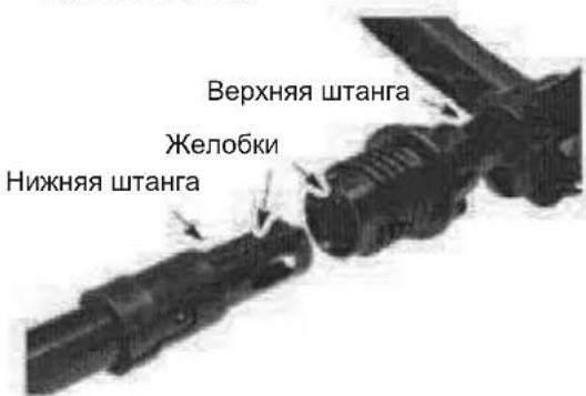
- CoeINHnTe WtAHn, BDbNHyB HxKHOU WtAHry B BepXHIO Do ynpa (WtAHn CcENnIOTc).
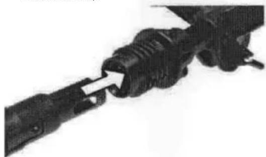
- HauBnHbTe HxKHO 即CTb COeHHHTeHbHO MyTbHa BepXHO 3aTHNE, NOBOPaUNBa No YacBOI CTpeNke.
PIMMEUHNE: Ecn coeunHntbHy MyfTy 3aTMyTb He ydaetc, uTaHn He CdBHyTb do ynpa.
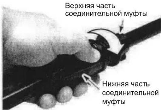
PERYJINPOBKA PUYKIN
PPEyIpyEHEHpeRpyuKny6eIITcB,TO OHa HaxoHTcMeJy pbyarom ra3a n CoeHNtBHyO MyfTy.
1.Ocna6bTe rainky-bapaaek Ha pyyke.
2. ПовернITE руку на Турб В Берхонноюжен; Chobа Затянite raиky -6apawek.
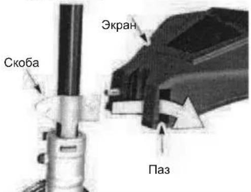
KPEINIEHNE 3AUINTHOFO 3KPAHA
ПЕДУПЕЖDEHNE:экpandoJxhen
6bIb npabnblHo yctaHOBHe. OH
06ecneuBaET qactNHyU 3aunTy
onepatopa N dpynx IIOeN OT
OT6paCbIbAembIX ppeMeTOB n O6OpyObaH
OrpAHnHTeJIEM, KOToPbB BbINOHNrE
OBpe3Ky NO BBICOTE. OrpAHnHTeNB
OBpe3Kn (pacnoJNOXeH NoD 3KpaHOM) OueHb
OCTpb- -o6 Hero MoXHO nope3aTbcra.
1.ΟΤΒΕρΗΝε ταῦκην Ḁλεκραήε.
2.YcTaHOBnTe CkO6y B n3 3KpaHa.
3.ПовернiteхранТаK,TO6bI 60NT npoewepe3OTBepCTne B Cko6e.
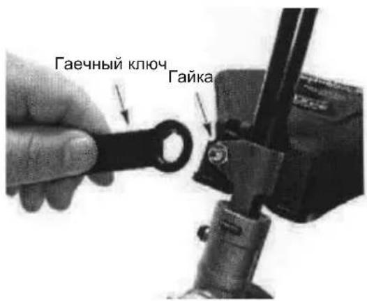
- Choba yctaHOBHTe raKy Ha MeCTO n 3aBepHnTe ee npn NOMOuN KIOUa (npnilaraetc).
3KCNJNYATAUH
PNEpyPEXDEHNE: Npe3anyckom Dnuratena y6eintecb, YTO Bbl BNIMATEIbHO O3HaKOMNINcB C npaBNAMn TEXHNK 6e3onacCHOCTn npoOBpaueHnC TOnNIbOM. EcInn Bbl He noHnnpaBN TPaBN TExHNK 6e3onacHOCTn, He 3anpabJrTe Bawe yCTpoiCTBO TOINBOM. O6paTntecb K ABTOPIN3OBAHHOMy DNlepy nO bcnykBaHIO yCTPOICTBa.
3ANPABKA DBNΓATEJIY TOIINBOM
IPEDyPEXEHEN: Pn3a npabke yctpoiCTBa TOnnBOM MeJneHNO tBopauBaIte KpbIuKy 6eH3o6ka. DAnHbI dBratJIb CeTINpOBOAH nPa60tI C He3TNIPOBAHbIM 6eH3HOM. Ipeed pa60ToB 6eH3HN CJeDeYet CMeuaTb C MOTOpHbIM MaclOM XopoUeRO KaueCTBa, PpeHa3NaYeHHbIM DnA DByXTaKTHbIX DBratEnC B03DuWbIM OXLnJxdeHHeM B COOTHOWeHn 50:1. CoOTHOWeHne 5:1 DOCTrAETC CMeuBANHeM 5 NITPOB He3TNIPOBaHHoro 6eH3HnA c 0,1 NITpa macna. HEJB3R POJIb3OBATbCR ABTOMOBHLbIM INu CYoOBbIM MacnOM. Macna Takoro TIna MOrYT NOBpeNTb DBratEn. Pn pnproTOBHeHn TOONBHOc Mecn CNeDuYnte Yka3aHnM Ha EMKOCTN C macnOM. Cpa3y xe NoCle Do6abHeHn Ma cna K 6eH3Hy BCTpxhNTE EMKocTB, YTObI obecneuHT bODhopHOe nepemeuBAHne Cmecn. IpexKeJe Yem BblONHrTb 3anpABky UcTPOcTBA TOnnBOM, 68a3aTeJIbHO npouTIne n Co6JIIOaIte npaBnA TeXnKn 6e3OnaCHOCTN, OTHOcUeCEK TOnnNBy.
OCTOPOXKHO! Hn B KOem cnyae He 3aIINBaIe B BaI dBnraTeIb Hepa36abIeHHb IeH3In. 3TO BB13OBET Heo6paTUMoe NOBpeJKeHne DnBraTeIa
TPEBOAHNAKTONINBY
IpIMHeTHe3TNINPOBaHbI6EH3HXopoWeroKaueCTBa.MnHmAlhBoe peKOMeHdyEMOe OKTaHOBOe YNCNo-90 (RON -DopOxHoe OKTaHOBOe YNCNo).
BAKHO
IcnoJIb3OBAHHe OInpTOcoDEpKaUx TOnnIB (B KOTOpBX CInpT CoCTaBnREt 60Jee 10%) MoKeT OTpuataJbHO CKa3aTbCra Ha xapaKTePncTnKax IN PPOJONKInTeNbHOCTn Cnyk6bl DnBnTaTeJIa.
PENyPExEHENHe: HeBepHoe
nPmHeHnE TOJINBa H/INn CMa3OHybIX MaTePnAIOB MOKeT PnVBecTN K CneDyUoIIM HeNCnpaBHOCTAM: HeBepHoE BKIOUeHne CUeJIeHn, nepeRpeB, 06pa3OBaHne «napoBOrO 3AMKa》,NOTepa MoUHOCTN, HApUeHne CMA3OHyBX CBOICTB, NOBpexDeHnE TOJINBOIpOBOIDOB, IPOKlaDOK IN BHYTpEHnX KOMNoHEHTOB KAp6HpTaOpa N T.D. CnInrTOcoDEpKaUne TOJINBa Bbl3IiBAOT CNlbHyO a6Cop6uH O BnaRn B ToJINBOMACsHHO CMECN C NocJeDyIOUeCenapaueHn TOJINBa MAcJa.
KAK BbIKJIIOUHTb
T30HOKOJIky
- BbIKIOHEny DnIaTeN yCTAHOBITe BbIKIOUaTeN bNOJoxHe N E Bbl.
KAK 3ABECTI RA3OHOKOJIky
PPEyPExHNE: Pn 3anycke DInrataTeI rONOBka ra3OHOKCNK 6bydTe Bpaatbcra. N36eraIte npNKoCHOBehn K rnyuHTeHIO. PpIKoCHOBehne K rOpAemy RfUwNTeHMOKET pNBECTN K OXKOrAM.
3ANYCK XOJODHORO DBNATENJI (n nn TeNloro DBratena nocne nonHoro pacxoda tonnna)
1.YCTaHOBNTe yCTpOHTBO Ha POBHOI NOBEXHOCTN.
2.YcTaHOBInTe BBIKHouaTeInb B NoIOXeHne BKn.
3. MeДпeнHo HaxMITE KHONky NOcoca 6 pa3.
4.YCTaHOBInTe pbyar BO3dUHNo 3acNOHKn B NOJIOKeHnI NOHOrO 3aKpbITnI 3acNOHKn.
5.HaKMTe uYdePbXnBaTe pBuaR r3a BO BpEMa BBIOJIHeHnBCEx yKa3aHHbIX HNKe DeICTBn.
6. Pe3ko DeepHInTe pykny shhypa cTapTepaTAK, yTO6bI pa3daJcR 3ByK, KaK 6ytdTo DBnIraTeNbIbIT aETcR 3aBeCTncB, Ho HeNoBToPraTe NOnbITOK 3anycka 6Oonee 6pa3.
7. KaK ToIbko Bbl ycblwnte 3Byk, KaK 6ytdo DnBraTeNb PbItaeTc 3aNcyTtBcR, yCTaHOBIne pbHar BO3dUshOH 3acNOHKn B noNoXKeHne HAnONoBHy 3akpbITOn 3acNoHKn (HALF CHoke).
8. Pe3ko DehpHnTe 5Hyp cTapTepa 1nna 3anycka DbrarateIe.Ecn n DbrarTeIb cpa3y He 3anyctnnc, NOBtOpnte NOnbItky He 6 pa3. Ecn DbrarTeIb He 3anyctnnc no cne 6 non bTOK (npn noLoXeHN BO3dyuHoh 3acNoHKn HALF CHOKE), yCTAHOBnTE pbUar BO3dyuHoh 3acNoHKn B NOLOXeHHe NOJHOrO 3akpbltna (FULL CHOKE) HaxMMte Ha noDcoC Kap6upopata 6 pa3. HaxMMte H depXnTe pbUar ra3a I DepHnTe WHyp cTapTepa eue 2 pa3a. YCTAHOBnTE pbUar BO3dyuHoh 3acNoHKn B NOLOXeHne HALF CHOKE n DepraTe uHyp cTapTepa Do 3anycka DbraratE, Ho He 6oone 6 pa3. PPMUEAHHE: Ecn DbrarTeIb BCE Xe He 3anyckaetc, To OH BO3MOxHo 3aInr. IpeeiDnTe K pa3deny 3AUYCK 3AJNTORO DBNRATEJI.
9. Nocne toro kak Dnuratentb 3aBeTeTc, daTe emy npabotatb B TeueHne 10 cekynd n 3aTEM yCTaHOBtpe pbuar BO3dyuHOn 3acNOHKn B OTKpbTOe noJIOXeHne (RUN). DaTe yCTpoiCTby
napa6oTaB B TeueHne 60 cekyHn npn OTkpblToB BO3dyuHoi 3acNoHke (RUN) n 3aTeM OTnyCTnte pbUar ra3a. IPIPMEAHNE: Ecnn DBruratEn 3arnox npn OTkpblToB BO3dyuHoi 3acNoHKe (RUN), yctahOBHTe pbUar 3acNoHKn B noJooKeHne HanoNobHy 3akpblToB 3acNoHKn (HALF CHOKE) n depraIte uHyp cTapTepa dna 3anycka DBruratEn, HO He 6pa3.
3ANYCKTOPRAEOTDBNIGATEJIJA
1.YCTAHOBNTe BBIKHIOHTeB B NOIOXHeHNE BKJ.
2. YcTaHOBnTe pblar Bo3DyUH0n 3acNoHKn B NOJIOKeHne HAnOIOBHy 3aKpbIToN 3acNoHKn (HALF CHOKE).
3. Haxmnte n Depxknte HaxaTbIM pbyar r3a. Depxknte pbyar nonHOCTbIO HaxaTbIM Do tex np, NOKA DBnraTeIb He HauyHET POBHO pa6oTaTb.
4. Pe3ko DeepHnTe UHyp CtapTepa nnycka DbrarateJ.Ecnn DbrarateNb cpa3y He 3anyCTnnc, NOBTOpHTe NOnbTKy He 60nee5pa3.
5.ДaIte DnraTeHIO nopabOtaB B TeueHne 15 cekyHn n 3aTeM yCTaHOBIne pbluaR BO3dyuHNo 3acNOHKn B NOJIHOCTbHO OTKpbItoE NOLOKeHne (RUN). IPNMEUAHNE: Ecnn DnBaTaeNb BCE Xe He 3anyctnnc, NOBTOPTE NOnbItky eue 5 pa3.Ecnn DnBaTaeNb BCE Xe He 3anyCKaETcA TO OH BO3MOXHo 3aNT.
3ANYCK 3AJNTOTO DBNIGATEJIJA
3aHbI B DnRaTeB MoKet 6bTb 3anye H NocpeCTBOM yCTAHOBKn pbyara BO3dyuHOI 3acNOHN B NOHOCbIO OTKpbItOE NOOKeHne (RUN). 3aTeM DepraTe uHyp CTapTepa dnydJIeHnN 3 DBnraTeN n3JINuKOB TOnnBa. B 3aBNCIMoCTN OT TOR, HACKONbKO CNJbHO 3aHT DBnraTeNb, Bam, BO3MOXHo, npndTCr DepraTb uHyp CTapTepa HeCKoNbKO pa3. EcIn DBnraTeNb BCE JxHe 3anyckaeTc, o6paTnTeCb K TABNJUe O6HAPyXeHnN I YCTPAHEHnR HEUCNPABHOCTEi
HNCPTPYLNO3KCPNYATAUIN NOLOXHENE PNI 3KCPNYATAUIN
PENyPEXDEHNE:Bcerda
NcNoB3yIte 3aunTy dna rna n yuei. HnKorda He haknoHnTecb nepecltpnye RoIOBko. KamHn nn Mycop Moryt cPnKOoWETb OT ra3OHOKOcnIKn nn MoryT 6bItb OTbpoWeHbI eIO BAM B rna3a nn NnIO npNBecTI K OcnenneHIO nn K dpYroCepBe3HO TpaMe.
He 3KcnnyatpyuTe Dnuratelb Ha ckopocTn, npeBbIaHoue Heo6xOdmyIO. CtpnxKa TpaBb I npOnCxOHT HauBoJe e 0fpeKTNBHO npn He NnHOCTbIO OTKpblTOI DPOCCeJIbHOI 3acNoHKe. Ppn NOHNKeHHoN CKOPoCTn Dnuratelb pOn3BOUIT MehSe Wyma n Bn6paun. Ppn 3tOM CTpnuyuaar CTpyHa 6byet Cnykntb DOJbWe n He 6ydet "PnBapNBATbc" K kATyKe.
EcnBbHe ctpnkeTe TpaBy,OTnyctnte pbiarra3a,yTO6bl DBIgateJIb pa6oTan Ha xOIOCTbIX O6OpOtax.
IIra octaHOBKn DnIaTeJIa:
-
Otnyctnte pbuar r3a.
-
YcTaHOBnTe BbIKNIOuATEJIb B NIOIOKeHne BblKJ.
INPEMEUEHNE T3OHOKOCHIKN INPCTPNKKE
IpepeMaTe ra3oHOKocnky, cnerka kacacb 3emn HnxHe yacTbO CTpnuye roNoBKn. Pn 3Tom DnRaTeNb DOJXeH pa6oTaB Ha nonHO CKOPoCTN. OrpaHnHTeNbHoe ne3Bne MeaJIInuecko CTpyHbl, npKpenNeHhoE K OCHOBAHIO, 6ydet 6pe3aTb Tpaby Ha COOTBeTcTBYIOUyIO BHCOTy.
PNDYPNEXHENE: NcnoB3yTe TOIbKO Kpyrnyo CTpyHy DnAmEtPOM 2 MM. Ppi dpyrom pa3mepe nnn dpyroon fOpme ctpyaHa He 6ydet HopMaJIbHO pe3aTb TpaByTO pnpBeTe K HApUSeHIO pa6Obl CTpIryuEe rOJOBKn IIN MoKet npVBecTu K cepbe3hBM TpaBMam. He NCNoNb3yTe dpyrHe MaTePnAJIb, TaKne KaK npBODa, ctpyHb, Tpocbi n T. n. PpOBOD MOKET pa3OpBaTcBra BO Bpemr CTPnKKn n CTAb ONaChbIM OpyXnEM, KOtOpoe MOKET Bbl3BaTb cepbe3HbTE TpaBMbl.
CNOO6blCTPNKKN
PENONb3yTe MNHIMaIbHyIO CKOpOCTb H He NpeperpyKaIte CTpyHy npCtpnKke TpaBb BOKpyr TBepDbIX PnpMeTOB (kAMKn, rpaBn, cTOn6bl 3abopa n T. n.), KOTOpBle MOryT NOBpeDHTb CTPnryUO roNOBky, 3anyTaTbCBA H He nn 6blb OTbpoWeHb IroNobKO, YTO MOKe TpNBcTn K TpaBMam.
KoHeC cTpyueyroJIOBKN peXeT TpaBy. HanNyUHne pe3yNbTaTbI MNHMaNbHbI n3HOC pExyuee cTpyHbIOCTnraETc npn noCTeNEHHOM BBODe cTpyueyen roJOBKn Ha TeppntOpNo, rde Heo6xOdmo BblNOJIHeHne cTpykKn. IpaBUNbHbI e HennpaBUNbHbI cnocobI cTpykKn noka3AhHnKe.
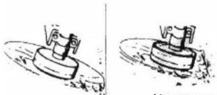
PpabnIbHO-KoHeC CTpyuee roIOBKn peKet TpaBy.
HenpaBnBHO- CtpyHa nonHocTbO BBeHeHa Ha MeTo BbINOnHeHr CTpNkN.
- Ctpnyuajra roJOBka MoKet JERKO ydaJIaTb TpaBy u copHAn BOKpyr cTeH, 3a6OpOB, DepeBBeB u KInyM6, Ho OHa TaKke MoKet Cpe3aTb MmRkyo Kopy DepeBBeB nn KyCTapHKnOB u NOBpeDnTb 3a6Op.
Дпя ПОДрзк ИЛУ ydaJIeHЯ pactNTeIbHOrO NOKPOBa He 3KcNlyaTnpyIte rAOHOKOCINKy Ha MAKCMaJIbHbIX O6OpOTax, YTO NO3BOJNTb yBeJIuHTb CpOK ee Cnyx6bl n CHn3NTb H3HOC TOnOBKn, Oo6eHNo B CneDyUOux CNYaX:
Bo Bpemn NOCTOARHHo H60nbwo Nope3Kn. - Okono npedmetOB, KOtOpbIe MOrYT 6bITb o6pe3aHbI CTpyuie IROBkoI, HAnpImep, He6oJIbUne CToJbKN, DepeBbIy HIN PBOJOnOHn3rOPOdb.
- XopoWero BbINOJIHeHn CKaUINBaHn HJN NOIMTeHn NcNOJb3yInTe Ra3OHOKOcNIky Ha NoHOM r3e.
CTPNKKA - Depxnte HxHKn Kpa CTpyuce RoOBKn RaOHOKOCUNKN Ha BbICOTE OKoJ0 8cm Had 3emJIe N IOd yrIOM. KOHTC TpaBOI DOJKeH OcyueCTBnTbcr TOJbKO KOHcOM CTpyuce RoOBKn. He npJaarateN n3NJuHNX ycNIIN dJn nepemeHnA CTpyuero 6noka B Mecte npoBeHeH na pa6OT.
8cm(3dnoMa)HaD3emn
YDAHEHPE PACTNTIELBHOPO NOKPOBA Ydaene HpeactntelbHoro NOKPOBA NO3BOJRAET DaNITb HexeJaTeNbHyO pactntelbHOCTb. Depxnte HxKHN Kpa CTpyuien RONOBKN Ra3OHOKCN HA Bbcote OKIO 8 CM HaD 3emJe I NOd yrIOM. PPy UdaenHn pactntelbHoro NOKPOBA BOKpyr DpeBBeB, CTON6OB, NaMTHIKOB T. n. DEpxnte CTPnyuho rONOBky Tak, YTO6bl ee KOHeC kacanc 3emNI. TaKaT ETKHKA NOBbIaet INHOC CTpyuero 6noka.
YDAJEHNE PACTNTBHOIPOBA
CKAUNBAHNE-BaHa ra3oHOKOcnKa
ndeaIbHO NOxOuNT dNra CkaUNBaHn TpaBb
TAM, rDe O6bUHbIe Ra3oHOKOcnKn He MOryT
NCNoIb3OBaTcBc. Pn CkaUNBaHn DEpKInTe
CTPnryuTO roNobKy npaNNenbHo 3emn.
N3eRaIte KacAHn roNobKn C 3emNe, TAK
KAK 3TO npNBedeT K ydaJIeHNIO cNoR 3emn IN
NOBpeKeJeHNIO ycToPiCTBa.
CKALUNBAHNE
IOMETAHNE-Bb6poc ctpyn BO3dyxa ot BpaauoueenCtprnyeRrOBKMOKet NcnoB3ObaTcN DnA 6bICTporo uNCTORO noDMaH.Nepxnte Ctrpyuoyro NOBky napaJIneMbHO NOBepxHOCTn Hn HAp NoDMTaemOn NOBepxHOCTbU H 3aTeM nepemeuaTe yCTPOJCTBO n3 CTOPOHb B CTOPHY.
ПОДМETAHNE
OBCNJYKINBAHNE
PNEyPExEHHE: Bce DeiCTBnno 06cIyKuBaHnIO,3a NCKIHyeHEm HAcTPOKn KAp6HpTaOpA, DOnJXhbl BbINONHrTbc npn OTcoEINHeHHo CBeue 3aKunraHn.
YBEINTEECB BOTCYTCTBUN OCJABXK PEPNEHNI DETAEN
KoJnnaQOK CBeuN
B03dyuHbIyHnIbTp
BnHTbI Kopnyca
BnHT BCNOMORAteIbHOB pyuKIN
3aunTHbIn 3kpA
YBEINTECB BOTCYTCTBNIIOBPEKDEHHbIX IN3HOWEHHbIXDETAJIEN
IIN 3aMeHbIOBpeKdEHHbIX INN H3HOWeHHbIX DeTaeN O6paTNTecb B aBTOp3OBaHHbI UeHTp No o6cnykBaHNIO.
BbIKIOyateNB -Y6eNTecb B HopMaJIbHOM 0yHKUHOHPOBAHn BBKIOyateJIyCTaHOBUB eO B noIOxHeN E BIKI. Y6eNTecb, yTO DBrATeNB BbIKIOuHNCra, 3aTeM 3aHOBO 3anyCTne DBIRATENB IN pOdoJXnTe pa6oTy.
TOnnINBbI 6ak - PpeKpaNTe NCNoJIb3OBAHne yCTpOJCTBa, ecNI TOnnINBbI 6ak IMeET cJeDbI NOBpeXdEHnUyTeKy.
- 3KpaH 3aIHTbI OT Mycopa - PpeKpaNTte
NcNoJIb3OBAHHe yCTpOHTBa, ecJI N 3KpaH
3aIHTbI OT Mycopa NOBpeKdEh.
OCMOTPNTENOCHNTY YCTPOICTBO N ETO HAKJIENKIN
- Pocne KaJdoRo NcNoJb3ObaHnO OcmOTpnte BCE yCTpojCTBO Ha HAnuHe OCna6uNX IIN NOBpeKDeHHbIX DeTanei. OuncTe YCTPOJCTBO HAKNeKn, INcNoJb3yR BIAxHyTO TkaHb, CMOueHHyO B HeITpaJIbHOM MOIOUem CpeIcTBe.
3aTeM npoTpne yctpoNCTBO uNCTOu cyxOu TKAHbO.
NOUICTNE BO3DyushbI ΦNJIbTP
3aarp3HeHHb BO3dyHbI qnIbTp CHNxaet 3KcNpyatauONHbIe XapakTepncTNkUyCTpoiCTBa, NOBbIaET pacxO TOnnBa UyBeINuBAe BpeHbIE BblOpcbI. BblONHMyte uCTky nocJe 5 yacob 3KcNpyatauINyCTpoiCTBa.
- Noucntte KpbuKny nOBepxHocTb BOKpyr Hee, TTo6bl npedotBpaNTb nonaHaHe rpa3n B KaMepy Kap6kpatopa npn CHrTm KpbuKn.
- CHMNTe DeTaN KaK 3TO NOKa3aHo Ha pucyHke.
PIMMEAHNE: He npomBaIte pInbTp B 6eH3nHe nB Dpynx rOpOuNX XNdkoCTX BO n36exKaHne PnCKa BO3rOpaHn IIN o6pa3OBaHn BpeDhIx napOB.
3.Помоу Te mьтВMbIbHOB OBe.
4. IpocyuTe fHnIbTp.
5. Hahecnte Ha qinbtp HeckoIbKO kaneMb Macna n coxMnte erO dner paBHomepHoro pacnpedeHnMa.
6. YctaHOBnte DetaHn Ha MeCTO.
KpbuKa Bo3DyUHOro QnIbTp
3AMEHA CBEUH 3AXIAHNIA
Igna 6nnerueHn 3ayncKa n HopMaNbHo npabotb DnurataTeN exeroHO MeHnTe CBeuy 3aKnraHn. 3a3Op MExdy KOHTaMn CBeuH DoJKeH CoCTABnTb 0,6 MM. BpeMnCKpOo6pa3oBaHn qNKcnpoBaHHe He perynpyetc.
- OTBepHnTe CBeUy n 3aTeM CHmMtE C Hee KOJINaOH.
- BbTaunTe CBeU y n3 UINHnpa n yTnNn3npyuTe ee.
- YctaHOBnTe HOByo CBeuy MapKn Champion QCJ-6Y n KaK CNeDyTe 3aTaNHe ee npn NOMOUs KNIOHa Ha 19 MM.
- YctaHOBIne Ha MeCTO KOJINaUOK CBeuN.
3AMEHA CTPNΓUULEN CTPYHbI
- Haxmnte Ha KcTOpbI NO KpaM rONOBKn TpMMepa N CHMnTe KpbIuKy n uynno.
- YdaIte octaBsyocr necky.
- YdaIte co BceX DeTanei rpa3b n 06pe3Kn. 3aMeHTe KaTyuKy, ecn OHa N3HOWeHa INN NOBpeKdHa.
-
YctaHOBnTe UnyIc yKe HAMOTAHHOJIeCKO INBCTABbTE B IMeHOUcHJyNIO HOByo QnpMeHHyIO JecKy DInHO4,5M dNaMeTpOM 2,4 MM.
-
Pn 3anpaBKe HOBOJ JecKn B MHeOuOcKaTyUkY DePknTe KaTyUkY, KAK NOKa3aHO Ha pucyHke.
- CoHNT e Nccky NocpeDnHe n BCTaBbTe Nccky MeCTOM CnBa B Na3 Ha CpeDhem OoJe uynu. YBeDnTEcb, yTo necka 3aΦNKcnpObaHa B na3e.
7.Дерka naene MeKdy DByM Kcckamn Neckn, HamaTbIbaTe IN NO YacOBON CTpeJIke Ha IInyIIO NIOTHO IN paBHOMepHo.
- yIoxnTe KpaJ IeCKN B HApBaJIIOUJIne na3bl.
- YcTaHOBnTe UnyIIO B KpbIiKy.
- PpoJeHbTe KpaI neKn B BbIXOdHbIe OTBepCTnHa CTopoHax KpbIuKN.
OTBepCTnA cepdeHnka
- YctaHOBNTe UnyIIO N KpbIuKy Ha CBOE MecTo B rOJIOBKe TpIMMepa.HaxMtTe, 4TO6bI KpbIuKa 3aUeJIKNHylnacb.
PEIYJINPOBKA KAPBIOPATOPA
PPEyPExHEHNE: PnpeynpOBKe
XOIOCTORo XODa NOCTOPOHHe DOnKHBi
HaxOHTbCn Ha 6e3onacHom pacctOAHn. B
XoJe 3ToI npOeDpybI ROJOBKa
ra3OHOKcNIKn 6yDenBpaauTbcr.. Pn
BbINOHNpeYIpOBok HadeBaTe
3aunTHoe 6OpdyoBaHne n Co6JIouaTe BCE
Mepbl IpeOCTOPOXHOCTn.
Kap6opatop 6bl TuaTeNbHO OTpeYIpOBaH
Ha 3ABOE-N3ROTOBITEe. PeryIpOBKa
CKOPOCTx OJOCTOro XODa Heo6XoDima B
Clyuae BO3NHKnHOBeHn OdHO N3
NepeuNCHeHHix HIXe CNTyaU.
- PnO tnyckAHn pykRa3a DnIraTeJIb He nepexoHT Ha xOIOCTbIe OOBOpTbI. BbINONHnIte peYInpOBKn npn NODHrTom yCTpoNCTBe IINrTO, YTO6blpeKyuaA hacaKa He Kacanacb 3emn HcconpNKacanacB C KaKIMn-Jn6o PneDmTaMn. Bo BpEMpa60tBJ yCTpoiCTBa n BbINOnHeHHa perynipOBOK depKNTe yCTpoiCTBO pkoJ. DePKeNTecb Ha 6e3oNaChOM pacCToRHNOT rnyuNTeJI n BpaauIoueenC cTpnryeien roJIOBKN.
PERYUNPOBKA XOIOCTbIX OBOPOTOB
JaTe DnurateIIO nepenHn XoJIOCTOxOJ. OtperynpyTe CKOpocTb DnurateJIa TAK, YTO6bl OH He IIOX (UTo npOnCXODIT npn CInuKOM Hn3KoN CKOpocTn XoJOCTOxoJa).
- NOBepHnTe BnHT peryJnIPOBKn XOJocTOro XoJa No YacOBon CTpeJIke, ecNn DniratEnb pe3KO c6paCbIBaET 06OpOtbl NNr IIOXHeT.
-Дя yMeHbWeHnA CKOpOCTN DBrIaTeJIa BnHT peryIuPobKx XoJocTOx XoJa Heo6XoIIMo NOBopaYBaTb IpOTNB YacOBOI CTpeJIKN.
EcnBAM Heo6xOIMMa DOnONHITeNBHnIOMOuB NIN BbI He yBepenb IB npaBnIBHOCTN BblONHeHNA3ToI pOueDpybI, OpaTnTEcK ABTOPn3OBAHHomPypeCTabNTeIO No 06CnykuaBHNO nnDnIepy.
XPAHEHNE
PNEyPExEHEN: Nocne KaJdoRo HcNoIb3OBAHnB, BblOnHnTe CNeDyUoune DeiCTBn:
- nepei xpaHHeHem mnn TpaHCnOpTnpOBko DaTe DBNrTaTeHIO OCTbITb.
XpaHnTe yCTPOIcTBO I TOJIINBO B XOPOI npoBeTpNaEMOM MeCe, rDe napbl 6eH3nHa He MOrTy CoPnKOCHyTbcr C NCKpAMN INN OTKpbITbIM PnAmHeM, BdaNt OT HArpeBaTeNeB OBoI, 3NeKTpOMOTopoB, pyBnIbHnKOB, Neey N T. I. - Ipeep xpaHennm mnn TpaHCnOpTnpOBko yctpoiCTBa CneIe TOONBO n3 6aka.
XpaHn Te yCTPOcTBO n EMKoCTN C TOnJIINBOM B MecTAX, HeIOCTyINbIX dIa JTei.
XpaHnte yctpoiCTBO CO BCEMn yctaHOBNEHHbIMHa HEm ORpaJDeHNMaPacnoJaTaTe yctpoiCTBO TaK, YTO6bI eOcTpbIE DeTaN He MOJI NaHeCTN TpaBMy
MEXKCE3OHHOX XPAHEHNE
B KOHcEce3OHa Hn,ecn yctpoCTBO He 6yET nCNoB3oBaTbC8 BoJee 30 dHe,ero HEo6XoDIMO NOrTOBtB K XpaHeHHo.
EcnBaue ycTpoNCTBO 6ydet XpaHnTbcra npoDJIKHTeBHOE Bpem:
- PeredДЛNTeHbIM XpaHEnEM KAKcIeDyET NOUcTHTe BCE yCTpoNCTBO.
XpaHnTe yCTpOYCTBO B YNCTOM cyXOM NOMEueHm.
Cnerka npotpnte MacJOM BHeHMe MeTJIInueckne NOBepxHOCTu yCTpoCTBa.
DBNΓATEJIb
- BbItaunTe CBeUy 3axnraHnI upe3 3To OTBepCTne 3aneIe B cUNINHp OdHy YaHHy IOxKy Macna dIy 2-TaKTHbIX DBriratenei (KomHaTOn TemnepaTypb).8-10 pa3 MeDInHo DePHnte UHyp cTapTepa IJa paBHOMepHoro pacnPpeJeHnMaCna.
- YcTaHOBInTe Ha MeCTO HOByIO CBeuy peKoMeHdyeMoI MapKn n C COOTBeTCTByIOUIM KAJIINbHBiM YICNOM.
- NounCTte Bo3dyuHbI qnJIbTp.
- Ocmotpnte BCE yctpoiCTBO Ha npedmet ocna6ux BnHTOB, raeK n 6oNTOB. 3aMeHnte BCE nobpejXdeHHbIe, noJOMaHHbIe nn H3HOWeHHbIe DeTaNN yCTPOiCTBa.
B Hauane cneDyUoJero ce3OHa NCNoJIb3yIte TOJIbKO CBExeE ToJIInBO C COOTBETCTBYIOUM COOTHOUSeHHeM 6eH3nHa N Macna.
DpyrOe
He nCnoJb3yIe ToTnNBO,ocTabueecra npoOnoro ce30Ha.
- Ecni TOnJIINBHaЯ emKoCTb Haayana pXaBeTb, 3aMeHHTe ee.
Deknapaqna cooBentbNA EC
Hommah, Bbinyctmba Hekapauio: Husqvarna AB, SE-561 82 Huskvarna,Sweden (TeI.: +46-36-146500)
Honnann Husqvarna AB npHHMaet Ha c6e Bc0 OTBcTBeHHocTh 3a PnlaTOpMy (PnlaTOpMbI) TpMMepa H/nn MOTOKocbl LT25NCOP, COOTBeTCTByOuJeMoDeJI (MOdeJIaM) TRIMMAC c cepNHBIM HomepaMn 2013 n 6oJee. Homep PnlaTOpMbI HOMep MoDeJI rCho yKa3aHb I TeKCTe Ha Ta6JIuHc TEXHNHeCKnx DaHHbIX HapA dy C rOdom N3rTOBLeHra N cepNHBIM HOMepom.
YkaaHHb Bblwe npeMeT deKnapauu cooTBeTcBye Tpe6oBAHnM cIeDyIOx DnpEeKTHCobeta EbpOnbl;
2006/42/EC Np Maunam n oobpydoBaHnIO (2006-05-17)
2014/30/EU Np 3neKtpomarHnTHoN COBmecTmocTn (2014-02-26)
2000/14/EC Np n3JnyeHnIO uyma B OKpykaioyio cpey (2000-05-08)
B COOTBECTBnC npIIOJxHeHem V DeKJIapuPoBaHHbI BeJIuHbI yPOBHa YyMa yKa3aHbI B TexHueCKo CneUΦNkaUnn pyKOBOdCTBa OpeaTopa.
TEXHNUECKNEXAPAKTEPNUCTUKN
MOdJIb:TRIMMAC(LT25NCOP)
ДВИГATEЛБ
O6beM,cm325
PnMaKcMaJIbHOm MOUHOCrI DBrIaTeTn, 06/MnH 8000
MaKcHmAbHaCkOoCTbBpaueHnBaI(WnHdJI),06/MnH 10000
HcnoobopoTOB DBnraTeT nppeKOMeHdyeMoMakCmMaIbHoCKopocTN BpaueHnBa nAa (wnHdE), 06/MnH 10000
PekomeHnyeMoE YnCNo XoNocTbIX O6OpOTOB, 06/MnH 4000
MaKcImaJIbHaI MoIHoCTb DBIrTaTeIa, I3MepeHHaB
COOTBcTbNcISO8893,KBT 0,6
TnyuTeBcKaTaH3aTopoM Da
CNCTEMA3AXKIGAHNIA
Cbea 3axnraHn Champion 3a3op meKdy 3JekTpoDAMN,MM 0,6
CNCTEMA NODAH TOIJIINBA N CMA3KN
Obem TOnnBHO 6aKa, cm3 340
PacxoTOnnnaPnpMaKcImaJIbHOmMOUHOCrDBrIraTeJRA,
3aMepeHHbI B COOTBeTCTBnC ISO 8893, r/uc 407
Pacxod yka3aHHO TOONIBA pnp MaKcMaJIbHO MOUHOCn DBINrTeN, 3amepeHHB B COOTBeTCTBnC ISO 8893, r/KBT.yac 768
BEC
Bec ctpnpyuero npncocobne Hnn 3kpaHa C npctbM 6akom, Kr 3,9
YPOBEHb WYMA
(cm.Ппмецанe1)
UpoBHeMoUHocTn UyMa, n3MepeHHbI dE(A) 109
UpoBHeH MoUHocTn UyMa, rapaHTnpoBaHHbI LwA, d6(A) 115
YPOBHN WYMA
(cM. PnmuMeaHne 2)
3KBnBaIeHTHbIe ypOBHN 3ByKOBOrO daBHeHnHa yu
nonb3OBaTeJn, n3MepeHb corlacho EN ISO 11806,
ISO 22868, έB(A)
C roIobKo TprMMepa (oprrnHaJIbHO) 100
YPOBEHb BnBPAuN
(cM. PnmuMeaHne 3)
YpOBeHb Bn6paun (ahy,eq) Ha pyUkax n3MepeH corlacho
EN ISO 11806 n ISO 22867 B M/c
C roIobKO TpIMMepa (opuHaJIbHO), NeBbIM/npaBBIM 8,9/7,5
PnmeHne 1: YpOBeH b Wyma B OKpykaHOue cpe De N3MepReTcKa KAK MoUHocTB 3Byka (LwA) coIacHo dInpeKTNB Ebponeckoro Co03a 2000/14/EC. Yka3aHHb ypoBeH b Wyma dJI MaunHb I3MepeH c opINHaJIbHbIM pexyUHM o6OpYOBaHNEM, daOHUM HANBbICWH yPOBeHb. Pa3Hnca MExdy rapaHTnpoBaHHbIM I3MepeHHbIM yPOBHeM Wyma B TOM, qTO rapaHTnpoBaHHbIM yPOBeH b Wyma TaKke BkIIOuayet pa36poc pe3yJbTaTOB I3MepeHm IN BapnaUIM MeXdy MaUNHaMn OndHOI TOJ Xe MoJeJI, coIacHo dInpeKTNB 2000/14/EC.
PnmeHne 2: Ka3aHHbIe DaHHbIe 06 3KBuBaJIeHTHom ypOBHe 7yMOBOrO daBHeHna dMaHHbI IMeOT TnunHbI cTaTnCTnHeckn pa3bpoc (cTaHdaprTHoe OTKIOHeHne) 1 D5 (A).
PnmeHne 3: Ka3aHHbIe daHHbIe o6 3KBuBaJIeHTHom ypOBHe Bn6paUIMeIOT TINuHbI CTaTNCtUeCKn pa36poc (CTaHapTHe OTKIOHeHne) 1 M/c2.
| Модень TRIMMAC (Кончим Вала Справосторонец peзьбов 5/16) | ||
| СоotВeтCTвуошee Долоннітěльhoe оборудане | Тип | Заша рекуцero оборудану, aprтукун №. |
| Триммерна roловka | TNG7 (trpoс 0 2 ММ) | 537419223/530096229 |
IIEPITPAΦH
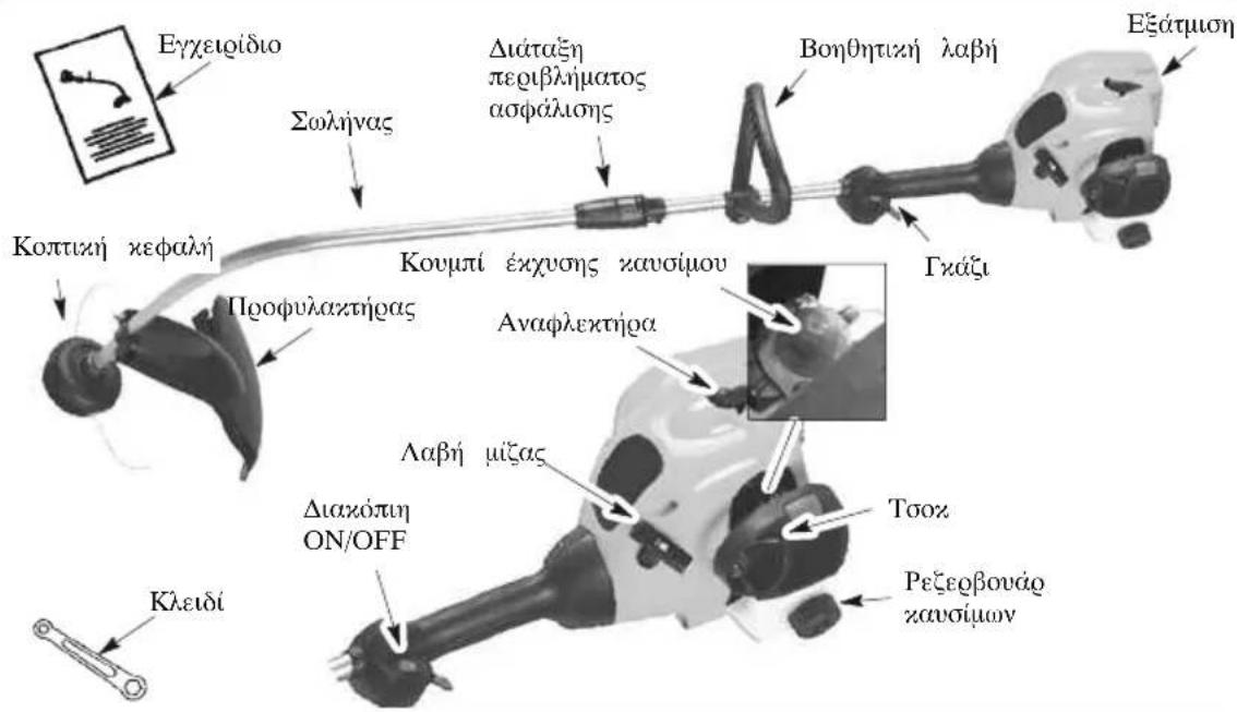
EIEEHGH\SYMBOA N


A. IPOEIAONIOIHSH! To xogtoxotuo uyncavnua unoepi va anodeixte eunivduo! H
aipooexn n xazn yonn uopei va npoxaleo e obao n axopa xai wopao tpaunouo.
B.Фgovtiote va diaafoe ta va xatavojoTe to Exyeiigio Xeiiguoov npv xonouoioeTo yooTOxOIOXo.
C. Me aun m lah, xonouoioitee movo n vdoan xonis. Nore m yonouoioitee aeidec n ouoxevcs xwnuatoa e ato to eoayaleio.
D. IPOEIAOIOIHsH! To yogroonnoo uogoe va neu e avnueeva biua. Yiaoya iivduvo ca vtofothe tva toauanotite. Na oooie nvy ta ayny noocia tvv noovoc.
TOIOOETHsH IIPOΦYAAKTHPA

IIPOEIAOIOIH2H:
O qoqfoaizjag avtoc qeTe va totothea oot.
O qoqfoaizjag papegei meqnn qooataia ao tov
xivouvo va nctaytov avnueieva oTo xeioutn ra ot
dAIOvX 11EVA EPODIAQAEVOG ME uA aeIDA anoxomis
Tov XALOSIOI TPO ANOXOTI To eauTO H
LAnOA anoxonis Tov XALOSIOI (xATo AO TO
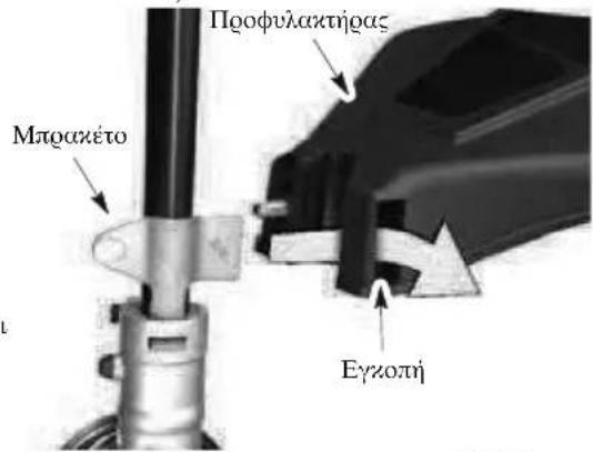
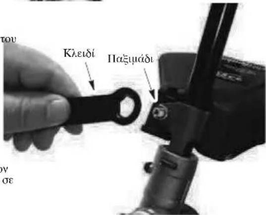
AEITOYPTIA

IIPOEIIOIOIH2H: Povrto va
diabioe 00a aogovv ta zavoua oovs xavoves aooaias, noiv axiote. Av dev nataaiaivee toux avoves oaoaiae, mny enxieoane va balee xainua oto unxavnu. Enzovovnote me eva Eevotodntuevo Seobt.
ANEΦOΔIAΣMOΣ ME KAYΣIMO

IIPOEIAOIOIHs: Oraovavartanpo
e Ta Xauou, va opagette Oya Xa npooexn To Xanax Tou doyoiou Xauoiou.
Aotc o uynnqde eivau ntoonuevoc yia leitouyia
ue aovuBnBevCIV. Nov ao tnLeuvogyia, n BvCIVN
poeTVA avayuyvetau neavn noornta laoti
diyoovos aegoyxous vnuo nov va exi
oxedaoei yia avaeien oe avaloyia 50:1.H avaloyia
50:1 enatvyxavetai avayuyovtac 5 litoa auovbng
BevCIVNS 0,1 litga naoiu MH
XPHIIMOIOEITE Ldai yua antoiznna n gnan
Ava ta laia gnoxaoiv cneus otov avnna. Ov aavayyve to xavouo, axolovnote t odnyes no avayapovra oto doxieio tou laoi.Moig to lau pooteei ont bevivn, avazynote onnuaia to cegebovag yia va bebaowdeite on to xavouo exeavauoyei owa Ta Ns daabae te na va axolovteire navtoe touxavovouos opqaleias ou oxeticovarue to xavouo ng avepodaioe Te movda aas.
IIPO2OXH: Not n xonauonoe ie oetn bevctin onuovada aac. daoepntua, 0a npoxnne iounu n Baaon oovxvnra.
AIIAITHSEEI KAYSIMOY
Xonauonouite auolubn BeVcIn xanig noiotntac. O
eunoros ouwawevoc agtuooc oxtavov eivat 90
(RON).
\SHMANTIKO
H xionxawouov noeogoxayao (u e Tegexntoana de axooan neyaooteon a 10%) uopei va geaaea oapago nnoaunata onv atdoon touvnnpaaoynv avthetaxtoana tou.

IIPOEIAOIOIH2H: H xonj
aovoiou kai/naivavov 0oovaleoepoogbauata
otc: Aovthetaevn eanoxn ouanextn, uveogoupov,
kieodua atov, anoleua wyooc, avenagxia
laivaoq, oogaaov tygauov kawouqou, tov
laaonov xai toy eovteqioov sagmuatov tov
xaupatee, ta. Ta vovuaov np tegiyov axooyn
poxaoleov nealn atogopnon yqaiaos ot
aeiya xavoiuoy/aidov tov 0a poaxaeoi oylo
diayooioo laiov xai zavoiou.
IIΩ Σ NA ΣTAMATHΣETE TO MHXANHMA
Tua aouarato 0 xavntnoos metaxavnote to dxaxoantn ont Oecn OFF.
IIΩ Σ NA BAAETE EMIPO Σ TO MHXANHMA
A IPOEIAOIOIHsH: H eaoaioo ngs yoiotov aoei oovnno. Atooivete 9. kthe enapn to onyaaonnH eatoum nov xaiet npooia va npoxaleoe oopapd eyazuaata.
EKKINH2H KPYOY KINHTHPA meta AIIO ANEPOIAaMO
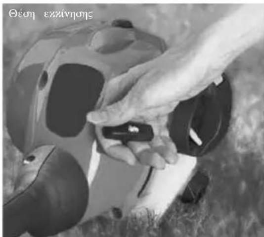
1.ToOnoOerntoe to unxavma πavo oε μa eπiδn EIOΦOVELOA
EIANEKKINHESH ZEETOY KINHTHPA
- Metaxunote to duxoON/OFF on theon ON.
2.Mataxwnote to toox onn 0eon (RUN). - Iaonote m oxavdaan. Koatnote narnneyn tn oxavdaan oto aneoc wotouva leuogynoe ouana
- Taqjnte aotoua to xogobv exzivnng va 5ekuvno o avugac, ala un to taqjnte npov ao nve Teo
5.AoIote rov zunmna va 15 devtegoe nna xai katoiv metaxinote to oo xon them RUN.
SHMEIOH: Av dev Seivnoe o avntnogc, TaqniTe to nooov exuvnoi neve axoyn qooec.Av na nn dev Seivnoe o avntnogac,piavov va exel uootei vreognnoo.
EKKINH2H TOY KINHTHPA OTAN EXEI YIIO2TEI YIIEPIIAHPQ2H
O xuvipas nov exu uovotel vuaqwnogom uogei va
eavnoe uauovotas to oo2 ont OenRUN
aupovtas to xoobov enkvivng ooe va xaravalooei n
peoiooetns beviving. Iowsv aoxeawntiva tgaibnve to
xoobov axvetes qoegs axoum, awihoya ue to baohu
wuganongos nov exu uovotel o uuvnpas, Av o
uvnpas eaxolouetva un eszwa, avapegeite orov
IINAKA ANTIMETQIIIEH IPOBAH-MATQN
OEESH AEITOYPTIAO EESH XEPIEMOY
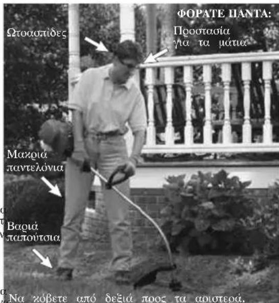

IIPOEIAOIOIHH:Φo@πaVα
a 1020 0000000000000000000000000000000000000000000000000000000000000000000000000000000
Mn leitouye tov auynnoa oe ueyaioteog taoynta
outn ou eivau ayxia. To zotuo vna 0 xoer
anotoleouana axon n aoy o yauuag aeueou
oe lyoteyn ao nguyo. Ze yauuoteegs taoynto
O auynnoas dnuuoyei Lyotego 0ofo Bo nai
kaadaoouc. To zotuo vna 0a diayoei
piqoiotego xn 0a vngovy Lyotene c naavotntes
Tuaei] OTO zapoiAI.
Oraov oraatae nV xom, va eAevthetae oavtoe Tn Ozavdaan va va eIepene Tov uimna va enoepel ony taoyma aodveua (peavvi).
Tia va stapatnoe Tn leitovoyia tov hyniqa: Aenveepoe Tn oxavdaan.
- Metaxwnote to daxoON/OFF orn the ON/OFF.
IIPOQOHJH NHMATOJ TOY TPIMEP
Iooxogone to zonxoxo xalodio xtuovtacs to 2aw
ngnns nepaans oto eaoosmu tov znuynqa
Lemouyei oanoy tonayra. H meaalua, ae
aoonigouov eviva noooqoquayn oto npoofwaztnog
Ox wipu to kdofo oto wadlno uip05.

IIPOEIAOIOIHsH: Xonouoovte
OVO OIOYIOV nuaue diaeetooov 2X. Tavnua EKIOIOWU OVEOUG Xa Oyauoos Dev Oa mooovv va POooOHTOIV Ooata Xa Oa exov os anotelEQA tv naan aeouovia ts xonwns xeapalns nyn pooxan obaqoi ToaunauoioMn XOauoTouie Aaaa ows ouqata, onayouc, oxivna aaaa. Av yonouonpoetoe ouqa, auo uogei va onaoi kana TIOAEXA TNS NNTS NVA vaaatganei oe enzivovdo ENOEVOVQoevo avxteiuevo nupogei va POnaaleo OOBAO TOaunauo. XOP
MEOAOI KOIHHE

IIPOEIAOIOIHs: Xonouooue
TIV EIAOIN Toaia Xa unv adnve to vua va axoataa n ta daiwaa a ts nois o diapoga onpa avaeuea (Teoe, xiaia, aoovouos an ophiies Xa hota) ta ootai uogoi yaoaoleovu baoi n rnaepai n Toutoqie, va moeovouiv oTo vina na expevdovotvi ngowawntos oobon cnua n tgaowauo.
Hxovivetau mTv axon tou vuaot. TaBaeiortn anodotixotra xai eaoitn 0oogatou vinaotos,my aphiote va xovetra bta oto oneio ts xomis. Pagato, vdoebvovtai ooooi ta o eoahevotgontoit xonis.
H xon yivea u e Tua bAwnn aOobotnnta axon tov vinaos. nAeAxuOnn oOpao Tou viuaos
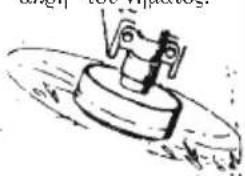

Σωτοι
Eoepauevo
To vua aqaei me eeyan exoia th xion kai ta 1cavia yuo ano toxouc, qoxtes, devta kai naogua, alia uoge i enoys va okei zai tov tougo pfio ano devo ra anoua zai va dnuuynnoa onudaa otov qoxtes. Ta to yalidoua n th ngioon baoonjx gonnoeite
ayoteo aio 1n oyo wote va diagzeoe to vua yia paooteo xovio daiotma xu va uadqe
ayoteog hooa ony zepaln, iattega:
Kata n biopexia aaoepus nonis
Kovda oe aunueeva ota oioia nogei va uaiybei to vina,6nwo osvloxouv,6evtg a
Tua aoteaouata meta n xogtozo n to
AAIAIEMA-Kaonto xaw dogo tnc xepalig v toe o kionoviaag aoe vipog pioitou 80 u. wao to edaofoGovtior eonwote mvo to daqo vnuuato exyetai oe enanm ne thxion.Mn xovete vua bda onnv npoyn ts xomie.
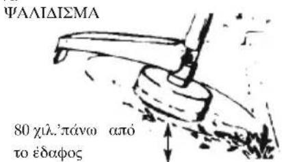
EeIOI - AiooovooTmy TeWnJ Eauwo,
Ooote va exo0ote ao to eaoos uapooa eo
avetoungn Baoonq. Koamto axo aoo ng
aeoigou to oueo o zion yovios na o inos paoiou 80
xA nnAo and to eaoos. Apno to axo oovuiocosva
Xuunoe OTO eadoos yiww ao nies, aoowou, maceg
na ooi. Exte vwny ouo nog otov aoolootheirinny
Teyai, to viua oieetua yiyoga.
EKPIZΩSH
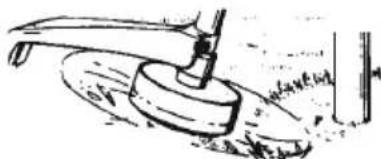
XOPTOKOH -To eoyaleio auo evua 1davno yia tvxooton o anuia onou ou nunues xogtoonntz es unxaves dev mooovv aexuv npoaan. Ka ta th daeena tns yogtoonm, qoantote to vna o Taagaaanr Toe n to edaooc. Mny nte tn xepaln OTO edapos duot auo Bt eige wc atoteaegua va Tetaytroiv xouata troyogw zau va uootei bao n to eoyaleio.
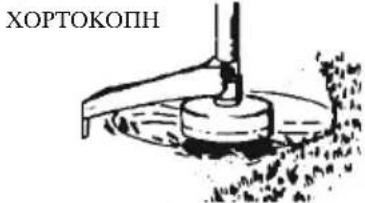
KAOAPIEMA XAOHE-O aogos nou dnmuovgyetai
aTO yonjyoga neqoiTepoevo vna uooge va
xonouoonei oto va quenete meaoia diaphoge
aaagoe aio ia ouzexgve npoyk.Keatnote
To vnae ae qadlan thn ao To edapoc nTv
Etuapeia nou thee va naagioe evo nuovate to
egyaaleio ano tn yia puega npoc tn alnn.
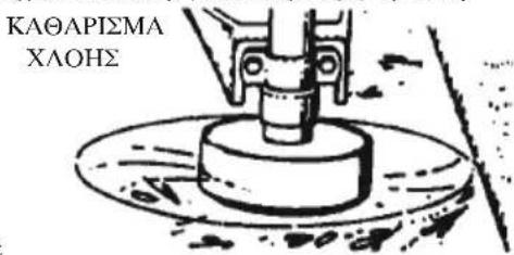
ΣYNTHPHH

IIPOEIIOIOIH: AOnovdeoe
to o v v xavete ouvugon, exto aio tou zauuvogateg.
EAETETIAYXONXAAPOY2 ΣFIKTHPEKAI EAPTHMATA
Piua Ynoooyjrs tov 2avthogor
ΦiAeog
Bides 2vyxpatnns to IVepiJuaTos
Bida Bontheta Xeepoalae
Aonida Hoootaoiaa aio Oqauata 2a Ytoalemuata
EAERETE IIA ΦΘAPMENA η KATEETPAMMENA EAPTHMATA
TnA vntaataaon xaneoqauevov n oaeveov
Egntauotav aeeuvthetae oe eva Egoovodnoevo
Zogt.
- DuaozonON/OFF. BeBauwtheta Tcog dozaoTOnON/ OFF toxog leuouyei oooia matauvovtacg to duazoTOnON/OFF ontchomOFF. Sryougevtte nog npnncnOaampe. Katoiv, eavvavhntn nnynmwnovexlote nnyeoxiaoc
Pegobovaoxovou. 1v gaetva Eaovonoyoantnoe to uynavna a v to gcegoabovaoov exi paei qnua n ex
Iooataeuro HeipBua. Taqantjote n xon ton egyaiou av to pooataeuro neiqiBua uooie BaaBn.
WARNING: Tampering with the engine voids the EU type-approval of this product.
EUV
PENyPExEHNHe: Hamecata B DmrgateJnpaBn HeBaIINHO EC OoObeHMeTO Ha TnHa To3N INpOdyKT.
EU V
UPOZORENJE: Neovlaštenim otvaranjem proizvoda ponistava se EU odobrenje tipa ovog proizvoda.
EU V
VYSTRAHA: Manipulace s motorem vede k zneplatneni typoveho schvaleni EU tohoto vyrobku.