
Cubix - Laser level STANLEY - Free user manual and instructions
Find the device manual for free Cubix STANLEY in PDF.
| Product type | Laser level |
| Brand | Stanley |
| Model | Cubix |
| Power supply | 2 AA batteries (LR6) |
| Leveling accuracy | ≤ 8 mm / 10 m (5/16 in / 30 ft) |
| Horizontal/vertical accuracy | ≤ 8 mm / 10 m (5/16 in / 30 ft) |
| Self-leveling range | ±4° |
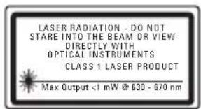
| Laser class | Class 1 (EN60825-1) |
| Wavelength | 630 nm ~ 670 nm |
| Operating range (line) | 12 m (40 ft) |
| Battery life | ≥ 12 hours (alkaline) |
| Protection rating | IP50 |
| Operating temperature | -10 °C ~ +40 °C (14 °F ~ 104 °F) |
| Storage temperature | -25 °C ~ +70 °C (-13 °F ~ 158 °F) |
| Main functions | Self-leveling, manual mode, cross line (horizontal and vertical), plumb, square |
| Maintenance and cleaning | Wipe with a soft, dry cloth. Do not use solvents. |
| Safety | Do not expose eyes to laser beam. Follow safety instructions in the manual. |
| Spare parts and repairability | For calibration, return the tool to the Stanley distributor. |
| General information | Use on a stable surface. Regularly check accuracy. Store with pendulum locked. |
Frequently Asked Questions - Cubix STANLEY
User questions about Cubix STANLEY
0 question about this device. Answer the ones you know or ask your own.
Ask a new question about this device
Download the instructions for your Laser level in PDF format for free! Find your manual Cubix - STANLEY and take your electronic device back in hand. On this page are published all the documents necessary for the use of your device. Cubix by STANLEY.
USER MANUAL Cubix STANLEY
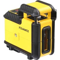
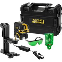
2 - Beam Self-Levelling Cross Line Laser
CUBIX
Self-Levelling
Please read these instructions before operating the product.


STHT77340
2 STHT77340
H5

J

J
J3
GB
Retain all sections of the manual for future reference.
User Safety

WARNING:
- Carefully read the Safety Instructions and Product Manual before using this product. The person responsible for the instrument must ensure that all users understand and adhere to these instructions.

WARNING:
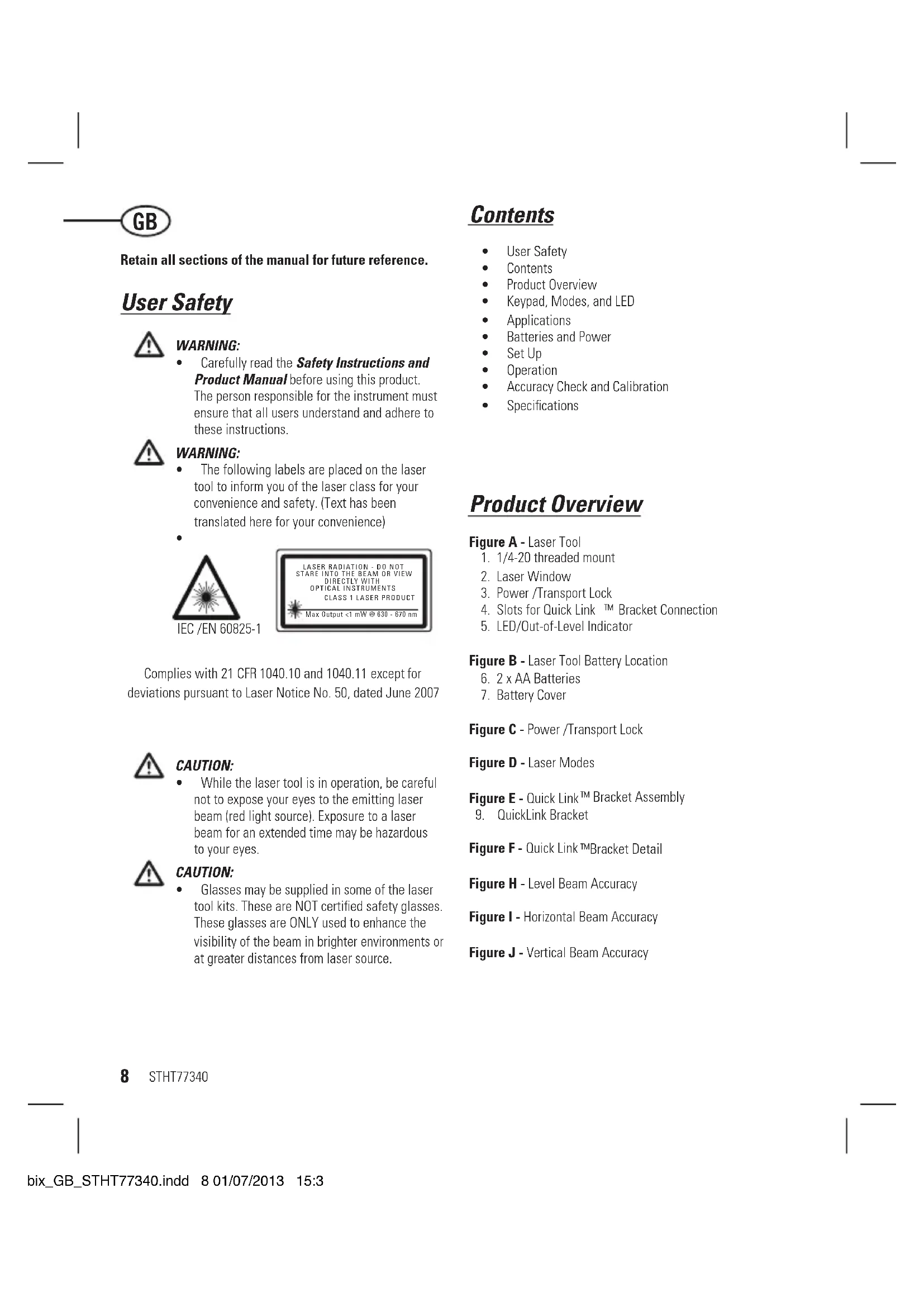
The following labels are placed on the laser tool to inform you of the laser class for your convenience and safety. (Text has been translated here for your convenience)

IEC/EN60825-1
Complies with 21 CFR 1040.10 and 1040.11 except for deviations pursuant to Laser Notice No. 50, dated June 2007

CAUTION:
While the laser tool is in operation, be careful not to expose your eyes to the emitting laser beam (red light source). Exposure to a laser beam for an extended time may be hazardous to your eyes.

CAUTION:
- Glasses may be supplied in some of the laser tool kits. These are NOT certified safety glasses. These glasses are ONLY used to enhance the visibility of the beam in brighter environments or at greater distances from laser source.
Contents
- User Safety
- Contents
Product Overview
Keypad, Modes, and LED
Applications
Batteries and Power - Set Up
Operation
Accuracy Check and Calibration
Specifications
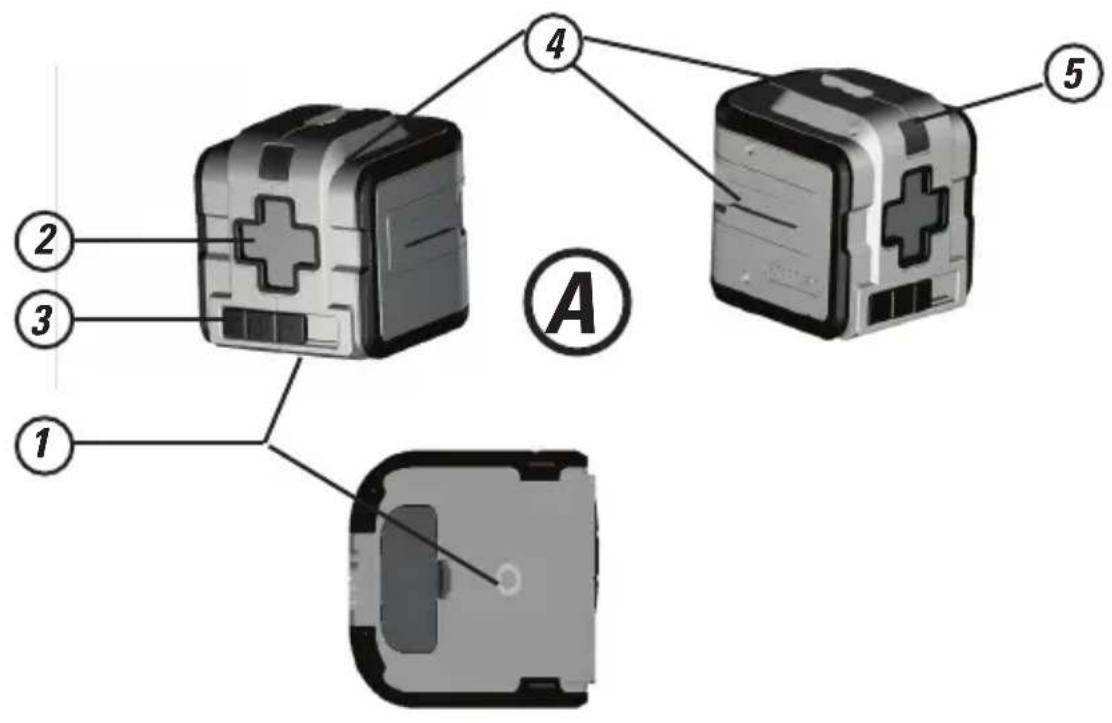
Product Overview
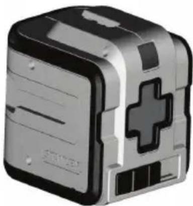
Figure A - Laser Tool
- 1/4-20 threaded mount
- Laser Window
- Power/Transport Lock
- Slots for Quick Link™ Bracket Connection
- LED/Out-of-Level Indicator
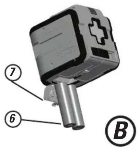
Figure B - Laser Tool Battery Location
- 2 x AA Batteries
- Battery Cover
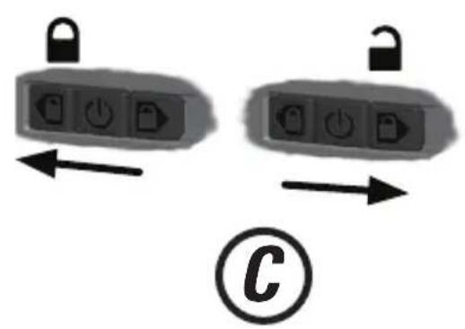
Figure C - Power /Transport Lock
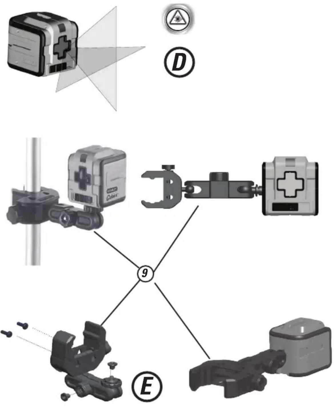
Figure D - Laser Modes
Figure E - Quick Link™ Bracket Assembly
- QuickLink Bracket
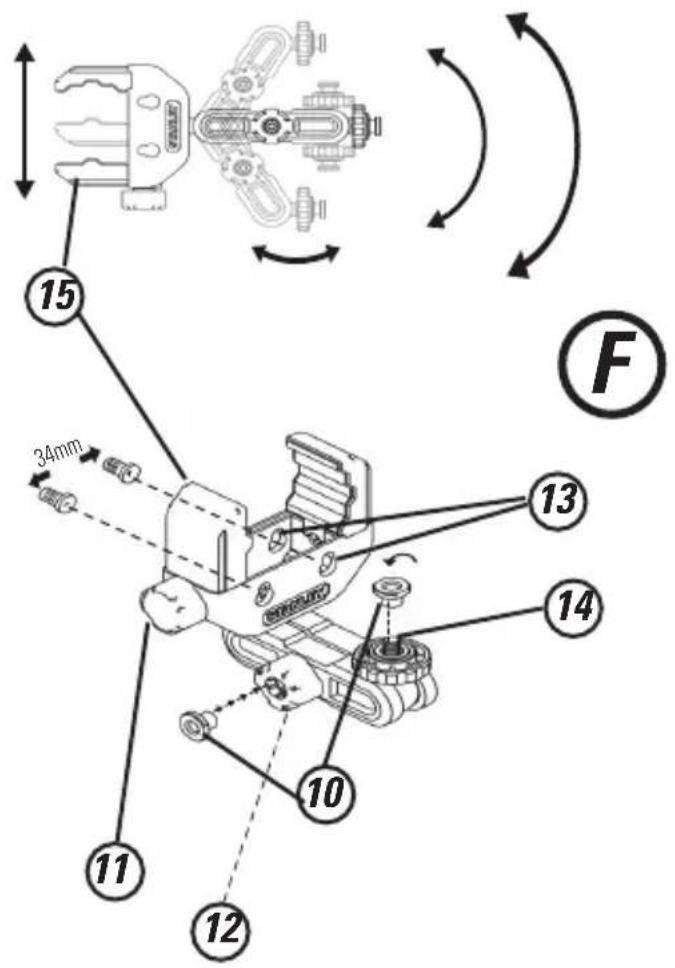
Figure F - Quick Link™Bracket Detail
Figure H - Level Beam Accuracy
Figure I - Horizontal Beam Accuracy
Figure J - Vertical Beam Accuracy
Keypad, Modes, and LED
Keypad/Switch

Power OFF/Pendulum Lock ON

Pendulum lock off /Self-leveling On

Pendulum lock on/Manual mode/
Self-leveling Off
- Move to the locked or unlocked position to turn the laser tool ON.
To turn the laser tool OFF, move to the centre position
All beams OFF
Modes
Laser Beam Available Modes
Cross Line ON (D.): Horizontal Beam Line and Vertical Beam Line ON
All beam lines OFF
Self-Leveling (See figures (C) and D)
- The pendulum lock on the laser tool needs to be switched to the unlocked position to enable self-leveling.
Manual Mode (See figures C and D)
- The laser tool can be used with the pendulum lock in the locked position when it is required to position the laser tool at various angles to project non-level straight lines.
LED/Out-of-Level Indicator Operation (See figure
A#5)

LED OFF
- Power is OFF/ Pendulum Lock is ON
- Power is ON, pendulum lock is OFF and
laser unit is within self-leveling range.
LED ON /Solid RED

laser unit is out of level.
or
Power is ON, pendulum lock is ON/ Self
Leveling is OFF.

QuickLink™ Bracket Overview
Figure F-QuickLinkTM Bracket
- T-nut to mate with slots on Laser Unit.
- Jaw Tightening Knob.
- Bracket Tightening Knob
- Hang holes for screw mounting. (34mm apart)
- 1/4-20" threaded mount.
- Adjustable Jaw
Bracket Applications
- The QuickLink bracket can be mounted in various positions by clamping the jaws to round or flat objects such as a tripod pole, door or bench.
The QuickLink bracket can be mounted on a vertical surface using the hang holes provided. (See figure #13)
The QuickLink bracket can be attached to the laser unit using the 1/4-20 threaded mount (Figure #14 and
figureA
1) or the t-nut and slot. Figure #10
STHT77340
Applications
Plumb Transfer
- Using the vertical laser beam, establish a vertical reference plane.
- Position the desired object(s) until they are aligned with the vertical reference plane to ensure object(s) are plumb.
Level Transfer
- Using the horizontal laser beam, establish a horizontal reference plane.
- Position the desired object(s) until they are aligned with the horizontal reference plane to ensure object(s) are level.
Square
- Using the vertical and horizontal laser beams, establish a poing where the two beams cross.
- Position the desired object(s) until they are aligned with both the vertical and horizontal laser beams to ensure objects(s) are square.
Manual Mode (See figures C
- Disables self-leveling function and allows laser unit to project a rigid laser beam in any orientation.
Batteries and Power
Battery Installation / Removal (See figure 8)
Laser Tool
- Turn laser tool to battery door and open.
Install / Remove batteries. Orient batteries correctly when placing into battery compartment. - Close battery door. Be sure that the door has been closed securely.

WARNING:
Pay close attention to the battery holder's (+) and (-) markings for proper battery insertion. Batteries must be of same type and capacity. Do not use a combination of batteries with different capacities remaining.
Set Up
Laser Tool
- Place laser tool on a flat, stable surface.
- If using the auto leveling feature move the pendulum / transport lock to the unlocked position. The laser tool must then be positioned in its upright position on a surface that is within the specified compensation range.
- The laser tool can be placed in any orientation and be functional only when the pendulum / transport lock is in the locked position.
Mounting on Accessories
- Position accessory in a place where it will not be easily disturbed and near the central location of the area to be measured.
- Set up the accessory as required. Adjust positioning to be sure accessory base is near horizontal (within laser tools compensation range).
- Mount the laser tool to the accessory using the appropriate fastening method to be used with such accessory / laser tool combination.

CAUTION:
- Do not leave the laser tool unattended on an accessory without fully tightening the fastening screw. Failing to do so may lead to the laser tool falling and sustaining possible damage.
NOTE:
It is best practice to always support laser tool with one hand when placing or removing laser tool from an accessory.
If positioning over a target, partially tighten the fastener, align laser tool, and then fully tighten.
Operation
NOTE:
See LED Descriptions for indications during operation.
- Before operating the laser tool always be sure to check the laser tool for accuracy.
- In Manual Mode, Self-Leveling is OFF. The accuracy of the beam is not guaranteed to be level.
- Laser tool will indicate when it is out of compensation range. Reference LED Descriptions. Reposition laser tool to be closer to level.
- When not in use, please be sure to power OFF the laser tool and place the pendulum lock in the locked position.
Power
- Move to the locked or unlocked position to turn the laser tool ON.
To turn the laser tool OFF, move to the centre position
Modes
Self-Leveling (See figures C and D)
The pendulum lock on the laser tool needs to be switched to the unlocked position to enable self-leveling.
The laser tool can be used with the pendulum lock in the locked position when it is required to position the laser tool at various angles to project non-level straight lines.
Manual Mode (See figures C and D)
- The laser tool can be used with the pendulum lock in the locked position when it is required to position the laser tool at various angles to project non-level straight lines.
Accuracy Check and Calibration
NOTE:
- The laser tools are sealed and calibrated at the factory to the accuracies specified.
It is recommended to perform a calibration check prior to its first use and then periodically during future use. - The laser tool should be checked regularly to ensure its accuracies, especially for precise layouts.
- When performing the accuracy checks, use the largest area / distance possible, closest to the operating distance. The greater the area / distance, the easier to measure the accuracy of the laser.
- The lock must be in the unlocked position to allow the laser tool to self-level before checking the accuracy.
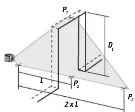
Level Beam Accuracy (See figure
- Place laser tool as shown with laser ON. Mark point P at cross.
- n_2 Rotate laser tool 180^ and mark point _2 at cross.
- Move laser tool close to wall and mark point P3 at cross.
Rotate laser tool 180^ and mark point _4 at cross.
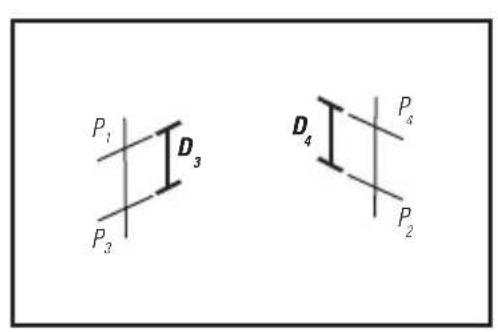
Measure the vertical distance between P_1 and P_3 to get D_3 and the vertical distance between P_2 and P_4 to get D_4 .
Calculate the maximum offset distance and compare to the difference of D_3 and D4 as shown in the equation.
If the sum is not less than or equal to the calculated maximum offset distance the tool must be returned to your Stanley Distributor for calibration.
Maximum Offset Distance:
Maximum
$$ = 0, 8 \frac {m m}{m} \times \left(D _ {1} m - \left(2 \times D _ {2} m\right)\right) $$
$$ = 0. 0 0 2 6 \frac {i n}{f t} \times \left\langle D _ {1} f t - \left\langle 2 \times D _ {2} f t \right\rangle \right\rangle $$
Compare: (See figure

$$ D _ {3} - D _ {4} \leq \pm \text {M a x i m u m} $$
Example:
D_1 = 10m,D_2 = 0.5m
D_0 = 0,5mm
D = -1,0mm
0.8mm x (10m - (2× 0,5m) = 7.2mm maximum offset distance
(0,5 ~mm) - (-1,0 ~mm) = 1,5 ~mm
1,5mm≤ 7.2mm
(TRUE, tool is within calibration)
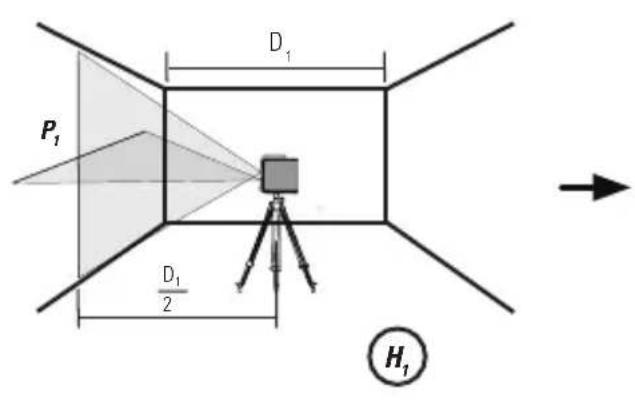
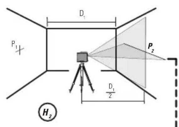
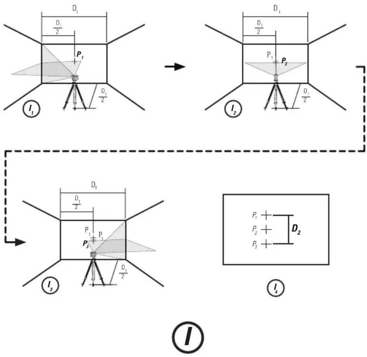
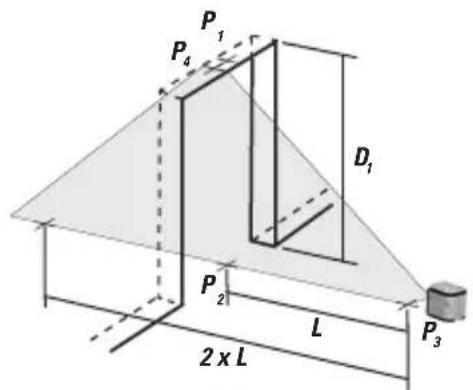
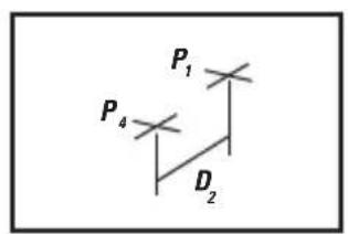
Horizontal Beam Accuracy (See figure ①)
- Place laser tool as shown with laser ON. Aim vertical beam towards the first corner or a set reference point. Measure out half of the distance D_1 and mark point P_1 .
- Rotate laser tool and align front vertical laser beam with point P_1 . Mark point P_2 where the horizontal and vertical laser beams cross.
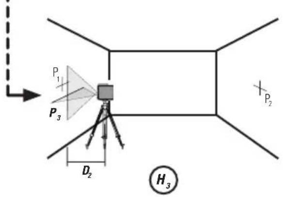
- Rotate laser tool and aim vertical beam towards the second corner or set reference point. Mark point P_3 so that it is vertically in line with points P_1 and P_2 .
Measure the vertical distance D_z between the highest and lowest point.
Calculate the maximum offset distance and compare to D2. - If D_2 is not less than or equal to the calculated maximum offset distance the tool must be returned to your Stanley Distributor for calibration.
Maximum Offset Distance:
$$ \begin{array}{l} \text {M a x i m u m} = 0. 8 \frac {\mathrm {m m}}{\mathrm {m}} \times \mathrm {D} _ {1} \mathrm {m} \ = 0, 0 0 2 6 \frac {\text {i n}}{\text {f t}} x D _ {1} f t \ \end{array} $$
Compare: (See figure 4)
$$ D _ {2} \leq \text {M a x i m u m} $$
Example:
D_1 = 5m,D_2 = 1,0mm
0.8× 5m = 4.0mm (maximum offset distance
1,0 mm ≤ 4,0 mm (TRUE, tool is within calibration)
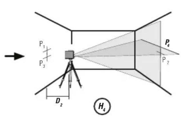
Vertical Beam Accuracy (See figure ①)
Measure the height of a door jamb or reference point to get distance D_1 . Place laser tool as shown with laser ON. Aim vertical beam towards door jamb or reference point. Mark points P_1, P_2 , and P_3 as shown.
- Move laser tool to opposite side of door jamb or reference point and align the same vertical beam with P_2 and P_3 .
Measure the horizontal distances between P1 and the vertical beam from the 2nd location.
Calculate the maximum offset distance and compare to Dp
If D_2 is not less than or equal to the calculated maximum offset distance the tool must be returned to your Stanley Distributor for calibration.
Maximum Offset Distance:
$$ \begin{array}{l} = 0. 8 \frac {\mathrm {m m}}{\mathrm {m}} \times \mathrm {D} _ {1} \mathrm {m} \ = 0, 0 0 2 6 \underset {\text {f t}} {\text {i n}} \times D _ {1} \text {f t} \ \end{array} $$
Compare: (See figure ③)
$$ D _ {2} \leq \text {M a x i m u m} $$
Example:
D = 2m,D_2 = 0.5mm
0.8mm x 2 m = 1.6 mm (maximum offset distance)
0,5 mm ≤ 1,6 mm (TRUE, tool is within calibration)
Specifications
Laser Tool
| Cubix(STHT77340 | |
| Levelling Accuracy: ≤8 mm / 10m (5/16in / 30 ft) | |
| Horizontal / Vertical Accuracy ≤8 mm / 10m (5/16in / 30 ft) | |
| Compensation Range: ±4° | |
| Working Distance (Line): 12 m (40ft) | |
| Laser Class: Class 1 (IEC/EN60825-1) | |
| Laser Wavelength 630 nm ~ 670 nm | |
| Operating Time (All lasers ON): ≥ 12 hours (Alkaline) | |
| Power Source: 2 x "AA" (LR6) | |
| IP Rating: IP50 | |
| Temperature Range (Operating): -10°C ~ +40°C (14°F ~ 104°F) | |
| Temperature Range (Storage): -25°C ~ -70°C (-13°F~158°F) | |
Notes
D
LED/Out-of-Level Indicator Operation (See figure
A#5)
LED AUS

Comparez: (Voir figure(5))
D_3 - D_4≤ ± Maximum
Example:
D_2 = 10m,D_2 = 0.5m
D_3 = 0,5mm
D_s = -1.0mm
0.8 × (10m - (2 × 0.5m) = 7.2mm (décalage maximal)
(0,5mm) - (-1,0mm) = 1,5mm
1,5mm≤ 7,2mm
Comparator: (Voir figure 4)
D_2≤ Maximum
Example:
D_1 = 5m,D_2 = 1,0mm
0.8 mm m x 5 m = 4.0 mm
(décalage maximal)
1,0mm≤ 4,0mm
Comparator: (Voir figure 3)
$$ D _ {2} \lesssim M a x i m u m $$
Example:
Specifications techniques
Outil laser
D_1 = 10m,D_2 = 0,5m
D_ = 0.5mm
D_4 = -1,0mm
0,8× (10m - (2× 0,5m) = 7,2mm
D_1 = 5m,D_2 = 1,0mm
0,8 mm x 5 m = 4,0 mm
Modo manual (Consulte as figuras C)
D_1 = 5m,D_2 = 1,0mm
0,8 mm x 5 m = 4,0 mm
Voeding is UIT/Pendulevergrendeling is AAN
- Voeding is AAN, pendulevergrendeling is UIT en laserenheid is Niet waterpas.
of - Voeding is AAN, pendulevergrendeling is AAN / zelfnivellering is UIT.
D_t = 5m,D_2 = 1,0mm
0.8 mm x 5 m = 4.0 mm (maximum offset afstand
1,0mm≤ 4,0mm
(TRUE, apparatus is binnen toleratie)
$$ D _ {2} \leq M a x i m u m $$
Voorbeeld:
D_1 = 2m,D_2 = 0.5mm
0.8 mm x 2 m = 1.6 mm (maximum offset afstand
0,5mm≤ 1,6mm
(TRUE, apparatus is binnen toleratie)
Technische gegevens
Lasermeter
$$ D _ {2} \leq M a k s i m u m $$
Eksempel:
D_1 = 5m,D_2 = 1,0mm
0,8× 5m = 4,0mm (maksimal offset-afstand
1,0mm≤ 4,0mm (SANDT,varktojet er inden for kalibreringen)
Nojagtighed af vertical laserstrale (Se figur
$$ D _ {2} \leq M a k s i m u m $$
Eksempel:
D_1 = 2m,D_2 = 0.5mm
0.8 mm x 2 m = 1.6 mm
(maksimal offset-afstand)
0.5mm≤ 1.6mm
(SANDT, varktojet er inden for kalibreringen)
Specificationer
Laservarktoj
| Cubix (STHT77340) | |
| Nivelleringsnøjagtighed: ≤8 mm / 10m | 5/16 tomer / 30 tod) |
| Horizontal / Verticaløjagtighed ≤8 mm | 10m (5/16 tomer / 30 tod) |
| Kompensationsområde: ±4° | |
| Arbejdsafstand (Linje): 12 m (40ft) | |
| Laserklasse: Klasse 1 (EN60825-1) | |
| Laserbølgelænge 630 nm ~ 670 nm | |
| Autonomia operativa: ≥12 timer (Alkalisk) | |
| Strømforsyning: 2 x "AA" (LR6) | |
| IP-klasse: IP50 | |
| Driftstemperaturområde: -10°C ~ +40°C (14°F ~ 104°F) | |
| Opbevaringstemperaturområde: -25°C ~ +70°C (13°F ~ 158°F) |
Bemærkninger
STHT77340 71
SE
Spara alla delar i manuales for framtida bruk.
Användarsakerhet

WARNING!
$$ D _ {2} \leq M a x i m u m $$
Exempel:
D_t = 5m,D_2 = 1,0mm
0,8× 5m = 4,0mm
$$ D _ {2} \leq M a x i m u m $$
Exempel:
D_1 = 2m,D_2 = 0.5mm
0.8 mm x 2m = 1.6 mm
$$ = 0. 8 \frac {m m}{m} x (D _ {1} m - (2 x D _ {2} m)) $$
Maksimum
$$ = 0. 0 0 2 6 \frac {\text {t o m m e r}}{f t} \times \left(D _ {1} f t - (2 \times D _ {2} f t)\right) $$
Sammenlign: (Se figur(5))
$$ D _ {3} - D _ {4} \leq \pm M a k s i m u m $$
EksempeI:
D_1 = 10m,D_2 = 0,5m
D_3 = 0,5mm
D_平 = -1.0 ~mm
0.8mm x (10m - (2x 0,5m) = 7,2 mm
(maksimalt tillatt avviksvstand)
(0.5mm) - (-1,0mm) = 1.5mm
1,5mm≤ 7,2mm
(SANN, laseren ligger innenfor kalibreringen)
$$ D _ {2} \leq M a k s i m u m $$
Eksempel:
D_t = 5m,D_2 = 1,0mm
0.8mmx5m=4.0mm
(maksimalt tillatt avviksvstand)
1,0mm≤ 4,0mm
(SANN, laseren ligger innenfor kalibreringen)
Noyaktigheavden vertikale stralen (Sefigur)
$$ D _ {2} \leq M a k s i m u m $$
Eksempel:
D_1 = 2m,D_2 = 0.5mm
0.8 mm x 2 m = 1.6 mm
(maksimal tillatt avviksvstand)
0.5mm≤ 1.6mm
(SANN, laseren ligger innenfor kalibreringen)
Tekniset tiedot
Laserlaite
| Cross90 (STHT77341) | |
| Nivelleringsnøyaktigkeit: ≤5 mm / 10m | |
| Horizontal / vertical nøyaktigkeit: ≤5 m/n / 10m | |
| Kompensasjonsrekkevidde: ±4° | |
| Arbeidsavstand (Linje): 10 m | |
| Laserklasse: Klasse 1 (EN60825-1) | |
| Laserbølgelende: 630 nm ~ 670 nm | |
| Driftstid: ≥15 timer (Alkalisk) | |
| Strømkilde: 2 x "AA" (LR6) | |
| IP-klasse: IP50 | |
| Betjeningstemperatur: -10°C ~ +40°C (14°F ~ 104°F) | |
| Lagringstemperatur: -25°C ~ +70°C (13°F ~ 158°F) |
Notat
PL
$$ D _ {2} \leq M a k s i m u m $$
Przyklad:
D_1 = 5m,D_2 = 1,0mm
0,8 mm x 5 m = 4,0 mm
$$ D _ {2} \leq M a k s i m u m $$
Przyklad:
D_1 = 2m,D_2 = 0.5mm
0.8 mm x 2 m = 1.6 mm
Ateevpyoioiog (OFF) npopooia / Evpeytoioi
ATREVEPYOtoiOnn (Off) kAeiδμaToC taλavTwaNs/
Everyponon (On) autoxwpoataeion

EvepyoioiOn (On) kaiidwpatoc taavtwos / Xepokivtn Aieioupyia /AtevepyoioiOn (Off) autoxwpootaui
Metakivote atn 0eon aopaiang n attaopaiang yia va epeyotoioge to epyaieio aeep.
Ia va aTVEpyoTioaTe To EpyaEio aeep, eTakivnoe Otv KevptkN t
- Ateevepytooinan (OFF) oawtww dσμw.
Tpotoi Aetoupyias
AiaTheoiIrpOIOI aeIOUpyiag doeunc leiEep
- Evεργοποιαση (ON) δίασταυμενων γραμμων (D1):
Evepytoioinan diaotaupwuevng kabetns kai opiciovia ypaunis
- Antevepytooinon (OFF) Tw ypaumw.
Autoxwooataogn(BaTeeOxyjuraCkaiD)
To kaiobwa taavtwong eitou evaaiou aeepipentei va metakivntheta nEa anapalianc yia va etipattei autoxwpoatauion.
Xeipokivtn λeivoupyia (Bλeπε σχηματα C καi D)
To epyaleio leiepi va xnpaiomoinei ie to kaeiodwa raavtwong otg oaoaipianosotavkati teio aataiteirai yvnt rooetnon Tou epyaleiou leiepuoi tio diapoeyswivc pokieevou v npobalee miaoatauoieves upeus
Aetoupyia Auxviac LED / Evdeiignc EKTOC Tepioxns XwpoTAtuionc (BAeTe OxHua #5)

ANTENEPRONOIHSH (OFF) AYXNIALED
Antepeyotoiogn (OFF) rpoofoocia / Evpeytoiogn (ON)
KAEiDomegaatGtahavtwon

Evepyoioan (ON) tropofoiaac, aTVEpyoioian (OFF)
KAEiBwUaTcAvaTwnCkIovadAeicEepEvTOsTouEupous autoxwooatauion.
Σταθερά KOKKINH
- EvpyoToinan (ON) Tpoopooiaoc, aTevpyoToinn (OFF) kEiOwpatoc taavtwonc kaiovadAaieCep EKTOs Tns TEPIOXnc xwooTaeMng.
- Evépyoioiog (ON) tpofooboiac, evépyoioiog (ON)
Meyi anooraon earomns:
$$ = 0. 8 \frac {\chi \lambda \sigma \tau}{\mu .} \times (D _ {1} \mu_ {.} - (2 \times D _ {2} \mu .)) $$
$$ \begin{array}{l} M E Y I O T O \ = 0, 0 0 2 6 \frac {i n}{f t} \times (D _ {i} f t - (2 \times D _ {2} f t)) \ \end{array} $$
D_1 = 5m,D_2 = 1,0mm
mm mm x 5 m = 4,0 mm (maximáni posun)
1,0mm≤ 4,0mm
(PLATI, prēsnost je dodržena)
Pnc.C-PnoKHeHnpeKeHnpeTeHnIHTaHn/6bOKnpOBKnMaTnHa
Pnc.D-Peknmbla3epa
Pnc.E-C6opka kpoonuTeHa Quick Link
9.KpOnuTeiN QuickLink
Puc.F-TeaIbHbIy UeptEx KPOHtEHa Quick LinkTM
Pcynok H-Touhoctb ypOBHn
Pcyhok I - ToHocb ropn3oHTaIbHorO nyuA
Pcynok J-ToocbBepTnKaIbHorO LyuA
Klauamypa, pekmbu cbe mododnbue udukamopb

KhoonouhnaheB/NepeKeHouateB
Kpamkoe onucaHue kpoHumeHa
QuickLinkTM
Pnc.F-KpohnteH QuickLinkTM
- T-ópbānáraiKa dπa Kpεπηηκ Na3am Ha Ia3epHOM npibope.
11.Pyuka dny 3aTnBAnHa 3axnMa. - Pukka dIa 3atraMbaHnKpOHsteHa.
- OTeBepCTnIy nIpy NOBBeWbAHnI npI MOHTaKe C NoMoUbBOHTOB (Ha paCCToRHH 34 MM).
- Pe3b60oe KpeHneHme 1/4-20".
- Perynpemybmyzaxmm.
06napu npumehnue kpohmeuHa
KpoHHTeIN QuickLink MoXHO yCTaHaBnBaTb B pa3hIx nOIOKeHHx, 3aФКСИРОВАВ 3aKHM Ha cΦepuYeCKHX INI POBhIX o6bektax, HAnPIMeP, HA HORE TpeHOM, DBeREx INI cKAMBe IN 3aTReHYB pyKHy. (CM. puc.F No11 u No12)
KpoHHTeIN QuickLink MOxHO yCTaHOBnTb Ha BepTmKanbHyIO NOBepXHOCTb C NOMOuIIO npOeJIaHHbIX OTBepCTM IIN IIN NOBeeWIMBAHN. (CM.puc. F No 13)
KpoHHTeIN QuickLink MOKHO npC0eHNHtB K HmKHeJ cA3n Na3epHOro np6opa, nONb3ype3b6boe KpennneHme 1/4-20" (cm. puc. F N214 u puc. A N21)nn KpennneHme T-06pa3Ho rAaN K na3y.
Pumehu
OTBec / Ipehoc ToeK
IcnoIb3yBepTnKaIbHbI Na3epHbI Ny, NoCTpoTe BepTnKaIbHyO KOHTPOJbHyO NIOCKOCTb.
-ДЯ obecneueHn OBecHOCTn Tpe6yemoro ObkeTa (ObeKeMoB) COBMECTnTe OBeKt (ObeKeMbI) C BepTKaJIbHOJ KOHTpONbHOJ PIOCKOCTbIO.
YpOBeHb/pepeHocToueK
IcnoB3yra ronp3oHTaHbHn na3epHbI nyu, noCTpoTe ronp3oHTaHbHyO KOHTPObnHyN NNOCKOCTb.
ДЯВыравиьанутpe6yemoroobekta(obekmo8)COBmecHTe obkT(obekmbi)Cropn3OHTaIbHOKHTpoJIbHOIIOCKOCTbIO.
YronbHnK
CnpoeuynTeBepTnKaIbHbI Hrop3oHTaIbHbI Na3epHbIe Iyu TAKIM O6pa3OM,TO6bI OHNpeceKaIINCB HYKHOI TOKe.
-ДЯ obecneueHnepenHnukyIpyHocn Tpebyemoro oBekTa (ObkeKmo) COBmctHe OBeKT (Obekmbi) C O6oMIM Na3epHbIM NjYamN.
PyuHOn peKHM (cm. pucyHKu ()
CpaHnmb: (cm. pucyHok _5
$$ D _ {2} - D _ {4} \leq \pm M a k c u m y m $$
Ppumep:
D_1 = 10M,D_2 = 0,5M
D_3 = 0.5MM
D_4 = -1,0MM
0,8 x(10M - (2× 0,5M) = 7,2MM
(MakcumaNbHO donycmumoe omKJtoHeHue)
(0,5MM) - (-1,0MM) = 4,5MM
1,5MM≤7,2MM
(umcpymem H TPEBYET kaIu6po8ku)
ToHocThROPn3oHTanbHorO Lyuca (cm. pucyHoK(
YCTAHOBHTe Na3epHbIM HNCTpymEt C BKNIOUeHHbIM Na3epoM, KAK NOKa3aHO Ha pucyKe. HanpaBtE BeptNKaJIbHbI NyuHa nebpbl yrOIN 3aADHHyO KOHTpOblHyTOky. N3mepbTe NOOBHy paCCTOHNr D1 IN OTMeTbTe TOky P1.
IIOBepHnTe Na3epHbI INCTpymENT H COBmecHTe NepeHnBePTNKaHbHbI Na3epHbI LyuC TOKOp P.OTMeTbTe ToKY PHa nepeceehnro np3oHTaIbHO r N BePtnKaJIbHO rNa3epHbIX Nyey.
10BepHnTe Na3epHbH INHCTpymeHT HnHaPaBbTe BepTKaNbHbIy Ha BTOPOYrOINN 3aDaHHyIO KOHTPOhHyTOkKy.OTMeTbTe TOkPy P HA OOnHOB BepTKaNbHOJ JINHmC TOKKAMn P nP2.
M3MpBe paccToHHe D no BepTnKaIIM MeKdy BbICSeI HN3Jei TOHKAM.
PaccuHTaTe MaKcHMaJIbHO DoIyCTHMoe OTKIOHeHne I cpaBHnTe erO c paCtOraHmE D2.
- Ecnu paccmohue D ,npeebwaem paccumahhoe makcunabho donycmumoe omknohene, uhcmpymehn heo6xodumo eephymb saewemy ducmpubomopy Stanley da Kaui6poeku.
MaKcumalbHo donycmUoe omKJIOHeHue:
$$ = 0, 8 \frac {M M}{M} \times D, M $$
MaKcumym
$$ = 0, 0 0 2 6 \frac {\partial I O U M}{\partial y m} x D _ {i} \phi y m $$
CpaHnmb: (cm. pucyHok
$$ D _ {2} \leq M a k c u m y m $$
Ppumep:
D_1 = 5M,D_2 = 1,0MM
MM 0,8 Mx5M=4,0 MM
(Makcumalbho donycmumoe omktoheHue)
1,0MM≤4,0MM
(UHcmpymem HETPE6YETKaiu6po8ku)
ToHocb BepTnKaIbHoro Lyuca (cm. pucyhoK)
U3MepbTe BlicOTy DBePHO rpoema NnKoHTpOblHOI TOckn (paCCmoHue D1).YctaHOBtne Ia3epHbN IHCTpyMeNT C BKIOUeHHbIM Ia3epOM, KaK NOKa3aHO Ha PNCyHKe. HanpaBBte BEpTKaJIbHbI NyuHa DBePBOH rpoem Nn KOnTPObHyTOchky. OTMeTbTe ToCKPi, P2 n P3, KaK NOKa3aHO Ha pCycHke.
12 Iepemecnte IaepHbI INCTpyMeHT Ha npOTNBIOJIOXHyIO CTOpOHy OT DBePHoI npOema NIM KOHTpOBHO TOKN COBmecTMeTO TOT Xe BepTKaJIbHbI NyC ToKAMN PnP3.
3 NImepbTe paccToHnne no ropn3oHTanm MeKny ToKoP P1nBepTKaJIbHbIM LyQOM, IpoeUpyEmbIM 2- ro nOIOKeHnA.
PacnTaeMaKcHmAbHoDOnyctHmoeOTKIOHeHneHcpaBHTero c paccToHnEM D.
- Ecnu paccmohue D 2 npeebuaem paccumahhoe mKcumalho donycmuoe omknlohenue, uHcmpymehm heo6xodmo eephymb eaewmy ducmpubomopy Stanley dnKaun6p8ku.
MakcumaIbHO donycmumoe omKJOnHeue:
$$ = 0, 8 \frac {M M}{M} \times D _ {1} M $$
$$ \begin{array}{l} M a k c u m y m \ = 0. 0 0 2 6 \frac {\partial \text {I O U M}}{\phi y m} x D _ {t} \phi y m \ \end{array} $$
CpaHumb: (cm. pucyHok 3
D_2≤ M C M M
Ppumep:
D_4 = 2M,D_2 = 0,5MM
MM 0,8 M x2M=1,6 MM
(MakcumalbHO donycmumoe omklohenue)
0,5MM≤1,6MM
(Unchmpymem HTEPBEYETKanu6poeku)
TexHuYeCKue xapaKmepucmuku
Ja3epHbI INHCTpymENT
$$ D _ {2} \leq M a x i m u m $$
Példa:
D_1 = 2m,D_2 = 0,5mm
0.8 mm m x 2 m = 1.6 mm (maximalan engedelyezett tavolsagelteres)
0,5 mm ≤ 1,6 mm (IGAZ, az eszkoz kalibralasa megfelelo)
Muszaki adatok
Lezereszkoz
D_1 = 5m,D_2 = 1,0mm
0,8 mm x 5 m =4,0 mm
(maximaln vzdialenost posunu)
1,0mm≤ 4,0mm
D_1 = 5m,D_2 = 1,0mm
0.8 mm × 5 m = 4.0 mm
TocTaBHe/M3BaXdaHe Ha 6aTePunTe (Bx. Puaypa B)
Ja3epeH ypei
3aBbpteteJiazephnI INHCTpymEnT KbdoHNuata.
OTbopeTe KaanaeTo Ha OTeJeHHeTo 3a 6aTePm, KaTo ro HATNCHEte NnB3Hete HABbH.
- NocTabete/N3BaTeTe 6BatePnte. Cna3eTe nonpaHocTtHa 6BaTePnte npn noctabraHTo mB napeHnyaypei.
3aTbOpTe n 3aKJIouTe KaIauTeHO Ha OTdeneHMeTO 3a 6aTePm, KATO rO p3HeTe, DOKATO upaKHe HA MCTOTOCN.
PPEyIpyKJDEHNE:
- O6bpheme bHUMaHue Ha 03HaueHuMa (+) u (-), 3a da nocmaume npabunho 6amepuume. Bamepuume mpr6ea da cbenadam no mun u 3apd. He u3non3eaume 6amepuu c pa3nUHO Hueo Ha 3apda.
YctaHObKa
Ja3epeH ypei
- NocTabeTe Ia3epHnI INcTpymEt Ha paBHa, cTaBnHa NOBbpxHOCT.
Ako n3no3BaTe fHyHKuYra 3a aBTOHbENIpaHe, npemecTe Te MaxanoTo /KnIOHa 3a TpaHCnOpTnpaHe BOTKIOUHO NOIOKeHne.CneTOBa Ia3ePHNHT HcTpymENT Tp6Ba Da 6bDe NoCTABeH B N3npaBeHO NOIOKeHne BbpyX IOBbPxHOCt,KoTTO Ce HAMIPA B ONpeJeHnKaOMNeHcAtOpEn Dnana3OH. - Ia3epHnT INhCTpyMeHT MoKe da 6bJe NOCTaBeH BvB BCaKaBb OpiEHnTp IN cyHKUHOHnpa eINHCTBEHO, KOraTO MaxaIIOTo / KIOuYbT 3a TpaHCnOpTnpaHe E B 3akNIOueHO NOIOXeHne.
MOnTnpaHHe Na npncTabKn
- NocTabete npncTabkata Ha MmCTo, KbTeTo Hma Da 6bDe necho nobpedeHa B 6JIn3OcT Do ceHtbpa Ha IIOuTa, KOrTO ue 6bDe n3MepBaHa.
I OIOROTBeTe pncTbKaTa, cNopei N3NCKBaHnra T P03NIOHnpaiTe taka, ye ochoBata Ha npctabKaTa da e 6JIn3o Do xOpN3OHTaNaTa (E KomneHcamOpHu duana3OH Ha na3epHu unHcmpymh). - MoHTnpaIe Ia3epHnI INCTpyMeH T bPxy npncTbKaTa KaTO n3oON3BaTe NOxOJaIa 3a TaKabA KOM6HaIaIg NpIcTabKa / Ia3epHnINCTpyMeH MeTo Ha 3aKpeNbaHe.

BHIMAHHE:
He ocmaaume naepnua uncmpymembpx npucmaka 63 nado3op u 63 da cme zameaHanu 3dpa0 3akpenauu BuHm. Ako He cnaume moea ycnoue, naepnua umhcmpymem moke necho da nadhe u da 6bde nopehen.
3A6EJIENKKA:
- Ppakmukama Hanaa euau, Kozamo nocmae unu cnaame naepnua uHcmpyMeH om npucmaKa, da npudbpxame uHcmpyMeHa c edha pka.
Ako 20 nozuohupame bpxuyen, yacmuho zamezheme 3akpenauu eHm, Hueuupaume la3epnua uHcmpymu m u ced moa zamezheme dokpaui.
ПоберkaHaToHocTtAnKaJIb6poBka
3AEBJEKKA:
Ja3epHume ypeo ce nnoMbupam u kanubpupam e 3aeoda 3a noocuHama myk moHocm.
- Ppenopbya ce da u38bpwime npoeepka ha kana6paumama npedu npeama ynomp6a u nppuoduho cnede moea.
TohocmHa na3epnua ype mpa6ea da ce npoeeprea peoeho, oc6eHno npu npue3Hu u3MepeaHua.
3aknoyeHemnpumpnOpmp6ea dae noloxehue omknouheo, 3a da moKe naepHuam uHcmpyMeH ma de caMOHeBnupa, npedu da ce npoeeprea moHocmma.
Ekncnoataua
3A6EJENKKA:
Bx. Onucanue Ha cemodouodume omHocho uDukaumme no epe me ha paoboma.
- Ppedu pa6oma buhazu npaeeme npoeepka ha mochocma Ha na3epnua ypeed.
Bpbunpekum camohueenupahemo u3knquho.He ce zapaanmua moHNO xOpuzOnmuane Ha Ibya.
Kozamo na3epnym ype de u38bN obxama ha komtehcamopa, moi nodaea cbomeemhama undukaua. Bx. Onucane Ha ceemododuode. Xopuzhmupaume makcumanno na3epnur ypeD
KoZamo He ce u3nOJ3ea, MoJra. yEepeMe ce, ye na3epHua m UHCmpyme H e u3KnIOUeH u MaxaIOMo e nocmaeHo 8 3aKIOUeHO NOJOKeHue.
Bknnoybahe
TpeMeCTeB3akIIOUeHOIMNOTKIOUeHOIOLOXeHne,3a Da BkIOUHTe Ia3epHOTO YCTPOCTBO.
3a da n3KJIOHTe Ia3epHOTO yCTPOIcTBO, IpemecTe B CpeHNO NIOXKeHne.
Pexm
CamohnBeHnpau/PbuehpeKm(Bx.Φuaypu C uD)
Maxanoto 3a 3aknoybahe Ha Ia3epnna HNCTpymehT py6Ba da 6bde B no3uyn OTKnueHo, 3a da e Bb3MOxHO CaMOHBeNIPAhe.
Ja3epnHr HNCTpyme MoKe Ja ce N3no3Ba C MAXaIOTo 3a 3akNIUOBAHe B NO3nue 3akNIUOeHO, KORATo Ja3epbT Tp6Ba Da ce No3nIOHnpa NOp pa3NJHn bTn 3a3aHTa Ha HeHNBeINPapn npabn JInHnn nN ToKKn.
ToHocHa Ibua 3a xOpunhtnpahe (Bx. Puaypa(H)
H1NocTabete na3epnna HnCTpyMeHT, KaKTo Ha nnIOCTpaunraTc BKNIOUeH na3ep. OTeBENExTe npeceHaTa TOnka C P1.
3aBpTeIaepHnIypeHa180°nOt6eKeTe npceuHaTaTOkaC P
HPiemeCTeIa3epnHa ype6bni3o do cTeHaOTBeJeKeTe npeceHata Toka C P
3aBbptete naepnna ypeHa 180° n otbeJeKeTe npceuHata ToKa c P.
H5N3MepeteBepTnKaIHOTo pa3cTOHHe MeJyP1uP3,3a da nOyuInTe D3 uBepTnKaIHOTo pa3cTOHne MeJyP2uP 3a da nOyuInTe D.
- 3NCHNETe MAKCMMAHOTO OTKIOHEHHe B pa3CTOHHaTaN cpaBHeTe C pa3NIkKaTa Ha D, IN D. KaKTo e NOKa3aHO BYpaBHeHNeTO.
Ako c6opbme no-maBk uU paeeH na3uucneHOMo MaKcumalno omKnOHeHue om pa3cmohemo, uHcmpymehb mP8ea da ce 6bpne npu ducmpubymopa Ha Stanley 3a kaun6pupahe.
MaKcumalHo omKnloHeHue om pa3cmOHaHEmo:
MM 0,8 Mx (D,M-(2xD.M)) MakcymM
Cpaeheme:Bx. quaypa
$$ D _ {3} - D _ {4} \leq \pm M a k c u m y m a $$
Ppumep:
D_1 = 10M,D_2 = 0,5M
D_3 = 0,5MM
D_d = 1,0MM
MM x (10M - (2x0.5M) = 7,2 MM (MaKcUMaJIHO omKnOHeHue om pa3cmOHaEmo)
(0,5MM) - (-1,0MM) = 1,5MM
1,5MM≤7,2MM
(BARPHO, uHcmpymemtbme KaIu6pupaH)
ToHOCHT Ha xOpu3oHTaHHnBbU (Bx. Puaypa)
10ctabete na3epnna HCTpymeh, KaKTo Ha nIOCTpaunra, C BKIOUeH na3ep. HAcOyTe BepTKaJIHH naBcKbM nbpBnB bIbn 3aJaDeHa pepepeHTa TOka. N3MepeTe NOOBnHata OT pa3CToAHHeTO Rn rO otBeJeKeTe c ToKa P1.
3aBbptTe Na3epHn INHCTpyMeHT nIOpaBHeTe npedHn BePTkAen H na3epENbC ToKa P. Ot6eJeTe TOkP2, KbTeOxOpNtAlHnT N BePTkAen Na3epHn PbHu Ce pecuat.
3aBbptete Na3epHn HNCTpyMeHT n HAcOyTe BepTKKaJIHn IbY KbM BTOPn BfJ INn 3aJaHe pedepeENTHa ToKHa. MapKnpaIe ToKHa P, taka Ye da e BepTKKaJIHO ycnpedHa Ha ToKn Pn P2.
6 IV3mepete BepTKaHOTo pa3ctOHNHe D2Mekdy HauBnCOKATA N HaH-HNCKATA TOKA.
- 3ucntete MaKcmaHTo OTKIOHeHne OT pa3ctOHHeTOI cpaBHeTe c D2.
AkoD He nO-MaIKO uu paHo Ha u3UcIeHomo MaKcUMaJIHO omKIOHeHue om pa3cmOraHemo, UHcmpyMeHmbl mPra6ea da ce ebpne npu ducmpu6ymopa Ha Stanley 3a KaIu6pupaHe.
MaKcumAnHo omKnloHeHue om pa3cmOHaEmo:
$$ = 0, 8 \frac {M M}{M} \times D _ {i} M $$
MaKcUMyM
$$ = 0, 0 0 2 6 \frac {\text {H H a}}{\text {F y T a}} x D _ {1} \phi y m $$
CpaHeme:Bx. qusypa 3
D_2≤ M c u m y m a
Ppumep:
D_1 = 5M,D_2 = 1,0MM
0.8 MM x 5M =4,0MM
(MakcumaHOn omKIOHeHue om pa3cmOHaEmo)
1,0MM≤4,0 MM
(BRPHO, uHcmpymeHmblm e KaIbpupaH)
ToHocHaBepTKaHHnIbU(BK.ΦuaypaJ)
J1N3Mepete BucOuHnHa Ha KacaTa Ha Bpata NIn pepepeHTHa ToKa, 3a Da NoIyUHe Pa3CToHnE D. IocTabeTe Na3epHnA INCTpyMeH, KaKTo Ha NIOcTpaunrTa, C BKIOueH Ja3ep. HAcOte BEPTKAKJIINH JbY KbM Kacata Ha Bpata NIn pepepeHTHa ToKa. O6BeNExeTe ToKn P, P2, n P3, KaKTo e NOka3aHO Ha NIOcTpaunrTa.
- Φ₂ ΠπeMeCTe Σaερa ΠσobpHaTa CtpaHa Ha Kacata
Ha BpaTATA ΜΠη peΦepeHTa TóUKa ΜπoPabHete
BéPTUKaJIHЯ NbU c P₂ Μ P₃.
3N3mepeteXOpn30HTaHHTpepa3ctOaHMeKdyP1nBepTKaHnIbUOTBtPOToMeCTONONOKeHne.
- 3ucnte MaKcMaHTo OTKIOHeHne OT pa3ctOHNeto cpabHete cD.
AkoD He no-MaIko unu pa6Ho Ha u3ucNeHomo maKcumAnHO omKnOHeHue om pa3cmOHaemo, uHcmpymHb mmp6Ba da ce 6bpne npu ducmu6yopopa Ha Stanley 3a KaIubpupaHe.
Makumalho omknlohehue om pa3cmohuemo:
$$ \begin{array}{l} = 0, 8 \frac {\mathrm {M M}}{\mathrm {M}} \times D _ {1} \mathrm {M} \ M a k c u m y m \ = 0, 0 0 2 6 \frac {N H U a}{\Phi y T a} \times D _ {t} \phi y m \ \end{array} $$
Cpaeheme: (Bx. quaypa
$$ D _ {2} \leq M a K c u m y m a $$
Ppumep:
D_1 = 2M, D_2 = 0.5MM
0.8 MM x 2M =1,6MM
(MaKcumaiHO omKnloHeHue om pa3cmouHuem)
0.5MM≤ 1.6MM
(BRPHO, uHcmpymemmbm e kaun6pupaH)
TexHnueckn daHHN
Ja3epeH ypei
| Cubix (STHT77341) | |
| Точность на的基础上可以接受: | ≤8 mm / 10m |
| Хоризонтailing / Вervикалha touchout: | ≤8 mm / 10m |
| Оьхbat на komпенсатор: | ± 4° |
| РавOTNO pa3stomonie (Пуня): | 12 m |
| Клас пазер: Клас | 1 (EN60825-1) |
| Дылхина на влина на пазер: | 630 nm ~ 670 nm |
| РавOTEN реким (пру онлайнения усучки льч): | ≥12 ча (Алkanег) |
| Зхсанове: | 2 x "AA" (LR6) |
| Оценистени на зашита (IP): | IP50 |
| Tempepatу老人家 диапазон за pавota: | -10°C ~ +40°C (14°F ~ 104°F) |
| Tempepatу老人家 диапазон за сбхсанे: | -25°C ~ +70°C (13°F ~ 158°F) |
3a6eJekn
STHT77340 159
RO
D_1 = 5m,D_2 = 1,0mm
0,8 x5m = 4,0mm
Maksimalais nobides attalums:
Maksimums
$$ \begin{array}{l} = 0, 8 \frac {m m}{m} \times (D _ {1} m - (2 \times D _ {2} m)) \ = 0. 0 0 2 6 \frac {\text {c o l l a s}}{\text {p e d a s}} \times \left(D _ {1} p \bar {e} d a - \left(2 \times D _ {2} p \bar {e} d a\right)\right) \ \end{array} $$
Salidzinajums: (Skat. attelu)
$$ D _ {3} - D _ {4} \leq \pm M a k s i m u m s $$
Piemers:
D_1 = 10m,D_2 = 0,5m
D_3 = 0,5mm
D_4 = -1,0mm
- 0.8 x (10 m - (2 x 0.5 m) = 7.2 mm (maksimalais nobides attalums)
(0,5mm) - (-1,0mm) = 1,5mm
1,5mm≤ 7,2mm
(PAREIZI, ierie icir kalibracijas robezas)
Horizontala stara precizitate (Skat. attelu 1)
D_1 = 5m,D_2 = 1,0mm
0.8 × 5m = 4.0 mm
(maksimalis nobides attalums)
1,0mm≤4,0mm
(PAREIZI, 1ericeirkalibracijrasrobezas)
Vertikāla stara precizitate (Skat. attelu J)
- Izmeriet durvu aplodas vai atsaues punkta augstumu, lai iegutu attalumu D Novietojiet lazera iceri ar iesegtulazeru. Vertikalo staru versiet uz durvu aplodu vai atsaues punktu. Atzimejetpunktus P_1 P_2 un P_3 ka paradits attela.
Pavietojiet lazera ierici uz pretejo durvju aplodas vai atsaues punkta pusi un izlidziniet vertikalo staru ar P_2 un P3 - Izmeriet horizontalo attalumu starp P_1 un vertikalo staru no 2. izvietojuma.
Aprekiniet maksimalo nobides attalumu un salfdziniet ar D 2
Ja D ^2 nav mazaks par(APREKINATO maksimalo nobides attalumu vai ir vienads ar to, icerice janogadā atpakaj Stanley izplatitājam kalibresanai.
Maksimailais nobides attalums:
$$ = 0, 8 \frac {m m}{m} \times D, m $$
Maksimums
$$ = 0, 0 2 6 \frac {\text {c o l l a s}}{\text {p e d a s}} \times D, p \bar {e} d a $$
Salidzinajums: (Skat. attelu 3)
$$ D _ {2} \leq M a k s i m u m s $$
Piemers:
D_1 = 2m,D_2 = 0,5mm
0.8 × 2m = 1,6mm
(maksimalais nobides attalums)
0.5mm≤ 1,6mm
(PAREIZI, ierie icr kalibracijras robezas)
Specifikacijas
Lazera 1erice
| Cubix (STHT77341) | |
| Limeşosanas precizitate: | ≤8 mm / 10m |
| Horizontal/vertikalprecizitate: | ≤8 mm / 10m |
| Kompensações diapazons: | ± 4° |
| Darba attalums (Linja): | 12 m |
| Lázera klase: | 1. klase(EN60825-1) |
| Lázera viljga garums: | 630 nm ~ 670 nm |
| Darbības laiks: | ≥12 stundas (sārna) |
| Barošanas avots: | 2 x "AA" (LR6) |
| Aizsardzības klase: | IP50 |
| Darba temperatūras diapazons: | -10°C ~ +40°C (14°F ~ 104°F) |
| Uzglabāsanas temperatūras diapazons: | -25°C ~ +70°C (13°F ~ 158°F) |
Piezimes
STHT77340 183
LT
Visas sio vadovo dorsis pasilikite, jei jj noretumete perziureti ateityje.
Naudotojo sauga

DÉMESIO:
D_1 = 5m,D_2 = 1,0mm
0,5× 5m = 4,0mm
(maksimalus kompensacinis atstumas)
1,0 mm ≤ 4,0 mm
(TRUE (TIKSLU), irankis sukablibruotas)
Vertikalaus spindulio tikslumas (Zr. pav. ①)
$$ D _ {2} \leq M a k s i m u m $$
Örnek:
D_1 = 5m,D_2 = 1,0mm
-0.8 mm m x 5 m = 4.0 mm
(maksimum yakinlastairma mesafesi)
1,0mm≤ 4,0mm
(DOGRU, alet kalibrasyonda)
$$ D _ {2} \leq M a k s i m u m $$
Ornek:
D_1 = 2m,D_2 = 0.5mm
mm 0,8 mkm x 2m = 1,6 mm (maksimum yakinlastirma
- 0.5mm≤ 1.6mm (DOGRU, alet kalibrasyonda)
Teknik Özellikler
Lazer Aleti
| Cubix (STHT77340) | |
| Hizalama Hassasiyeti: | ≤8 mm / 10m |
| Yatay / Dikey Hassasiyet: | ≤8 mm / 10m |
| Dengeleme Araiğl: | ± 4° |
| Delovna razdalja (Linija): | 12 m |
| Çalıkma Mesafesi (Nokta): Sinif | 1 (EN60825-1) |
| Valna duljina lasera: | 630 nm ~ 670 nm |
| Lazer Dalga Boyu: | ≥12aat (Alkalin) |
| Çalıkma Süres | 2 x "AA" (LR6) |
| Güç Kaynabr: | IP50 |
| IP Derecesi: | -10°C ~ +40°C (14°F ~ 104°F) |
| Çalıkma Sıcakkıngı Araliğl: | -25°C ~ +70°C (13°F ~ 158°F) |
Notlar
STHT77340 207
STANLEY.
© 2013 Stanley Black and Decker, Inc.
© 2013 Stanley Tools,
701 East Joppa Road,
Baltimore, Maryland 21286
www.STANLEYLASERS.com
A-07
- CUBIX
- GB
- Retain all sections of the manual for future reference.
- User Safety
- WARNING:
- CAUTION:
- Contents
- Product Overview
- Keypad, Modes, and LED
- Self-leveling Off
- Modes
- Laser Beam Available Modes
- Self-Leveling (See figures (C) and D)
- Manual Mode (See figures C and D)
- LED/Out-of-Level Indicator Operation (See figure
- LED ON /Solid RED
- QuickLink™ Bracket Overview
- Figure F-QuickLinkTM Bracket
- Bracket Applications
- 1) or the t-nut and slot. Figure #10
- Applications
- Plumb Transfer
- Level Transfer
- Square
- Manual Mode (See figures C
- Batteries and Power
- Battery Installation / Removal (See figure 8)
- Laser Tool
- Set Up
- Mounting on Accessories
- NOTE:
- Operation
- Power
- Self-Leveling (See figures C and D)
- Accuracy Check and Calibration
- Level Beam Accuracy (See figure H
- Maximum Offset Distance:
- Example:
- Horizontal Beam Accuracy (See figure ①)
- Compare: (See figure 4)
- Vertical Beam Accuracy (See figure ①)
- Compare: (See figure ③)
- Specifications
- Notes
- D
- LED AUS
- Comparez: (Voir figure(5))
- Comparator: (Voir figure 4)
- Comparator: (Voir figure 3)
- Specifications techniques
- Modo manual (Consulte as figuras C)
- Voorbeeld:
- Technische gegevens
- Eksempel:
- Nojagtighed af vertical laserstrale (Se figur
- (maksimal offset-afstand)
- (SANDT, varktojet er inden for kalibreringen)
- Specificationer
- Bemærkninger
- SE
- Spara alla delar i manuales for framtida bruk.
- Användarsakerhet
- WARNING!
- Exempel:
- Sammenlign: (Se figur(5))
- EksempeI:
- (maksimalt tillatt avviksvstand)
- (SANN, laseren ligger innenfor kalibreringen)
- Noyaktigheavden vertikale stralen (Sefigur)
- Tekniset tiedot
- Notat
- PL
- Przyklad:
- Tpotoi Aetoupyias
- Autoxwooataogn(BaTeeOxyjuraCkaiD)
- Xeipokivtn λeivoupyia (Bλeπε σχηματα C καi D)
- Σταθερά KOKKINH
- Meyi anooraon earomns:
- Klauamypa, pekmbu cbe mododnbue udukamopb
- Kpamkoe onucaHue kpoHumeHa
- QuickLinkTM
- Pnc.F-KpohnteH QuickLinkTM
- 06napu npumehnue kpohmeuHa
- Pumehu
- OTBec / Ipehoc ToeK
- YpOBeHb/pepeHocToueK
- YronbHnK
- PyuHOn peKHM (cm. pucyHKu ()
- Ppumep:
- ToHocThROPn3oHTanbHorO Lyuca (cm. pucyHoK(
- MaKcumalbHo donycmUoe omKJIOHeHue:
- CpaHnmb: (cm. pucyHok
- ToHocb BepTnKaIbHoro Lyuca (cm. pucyhoK)
- MakcumaIbHO donycmumoe omKJOnHeue:
- CpaHumb: (cm. pucyHok 3
- TexHuYeCKue xapaKmepucmuku
- Példa:
- Muszaki adatok
- TocTaBHe/M3BaXdaHe Ha 6aTePunTe (Bx. Puaypa B)
- Ja3epeH ypei
- PPEyIpyKJDEHNE:
- YctaHObKa
- MOnTnpaHHe Na npncTabKn
- BHIMAHHE:
- 3A6EJIENKKA:
- ПоберkaHaToHocTtAnKaJIb6poBka
- 3AEBJEKKA:
- Ekncnoataua
- 3A6EJENKKA:
- Bknnoybahe
- Pexm
- CamohnBeHnpau/PbuehpeKm(Bx.Φuaypu C uD)
- ToHocHa Ibua 3a xOpunhtnpahe (Bx. Puaypa(H)
- MaKcumalHo omKnloHeHue om pa3cmOHaHEmo:
- ToHOCHT Ha xOpu3oHTaHHnBbU (Bx. Puaypa)
- MaKcumAnHo omKnloHeHue om pa3cmOHaEmo:
- CpaHeme:Bx. qusypa 3
- ToHocHaBepTKaHHnIbU(BK.ΦuaypaJ)
- Makumalho omknlohehue om pa3cmohuemo:
- Cpaeheme: (Bx. quaypa
- TexHnueckn daHHN
- 3a6eJekn
- RO
- Maksimalais nobides attalums:
- Salidzinajums: (Skat. attelu)
- Piemers:
- Horizontala stara precizitate (Skat. attelu 1)
- Vertikāla stara precizitate (Skat. attelu J)
- Maksimailais nobides attalums:
- Salidzinajums: (Skat. attelu 3)
- Specifikacijas
- Piezimes
- LT
- Naudotojo sauga
- DÉMESIO:
- Vertikalaus spindulio tikslumas (Zr. pav. ①)
- Örnek:
- Ornek:
- Teknik Özellikler
- Notlar
- STANLEY.
Brand : STANLEY
Model : Cubix
Category : Laser level