STG404 - String trimmers GREENWORKS - Free user manual and instructions
Find the device manual for free STG404 GREENWORKS in PDF.
User questions about STG404 GREENWORKS
0 question about this device. Answer the ones you know or ask your own.
Ask a new question about this device
Download the instructions for your String trimmers in PDF format for free! Find your manual STG404 - GREENWORKS and take your electronic device back in hand. On this page are published all the documents necessary for the use of your device. STG404 by GREENWORKS.
USER MANUAL STG404 GREENWORKS
2 General power tool safety warnings. 4
3 Installation. 4
3.1 Unpack the machine 4
3.2 Attach the guard 4
3.3 Assemble the shaft. 4
3.4 Attach the auxiliary handle.. 5
3.5 Install the battery pack.. 5
3.6 Remove the battery pack.. 5
4 Operation. 5
4.1 Start the machine 5
4.2 Stop the machine 5
4.3 Operation tips.. 5
4.4 Cutting tips.. 5
4.5 Adjust the length of the cutting line.. 5
4.6 Line cut-off blade.. 5
4.7 Adjust the cutting diameter.. 6
4.8 Use the shoulder strap.. 6
5 Maintenance. 6
5.1 General information.. 6
5.2 Clean the machine 6
5.3 Remove any remaining line.. 6
5.4 Install the cutting line.. 6
5.5 Remove the trimmer head.. 6
5.6 Assemble the trimmer head.. 6
6 Transportation and storage. 7
6.1 Move the machine 7
6.2 Store the machine. 7
7 Troubleshooting. 7
8 Technical data. 8
9 Warranty. 8
10 EC Declaration of conformity. 8
1 DESCRIPTION
1.1 PURPOSE
This machine is used to cut grass, light weeds, and other similar vegetation at or around ground level. The cutting plane must be approximately parallel to the ground surface. You cannot use the machine to cut or chop hedges, shrubs, bushes, flowers and compost.
1.2 OVERVIEW
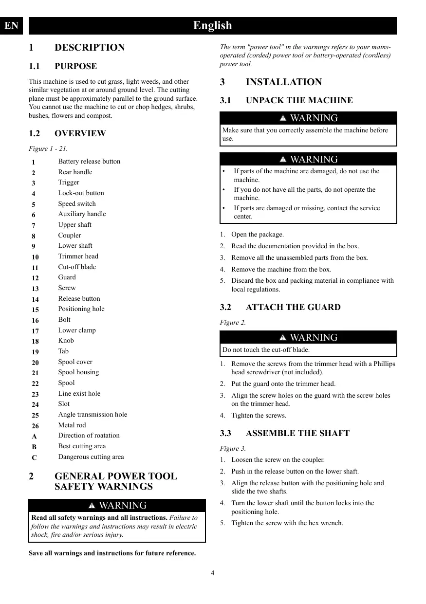
Figure 1 - 21.
1 Battery release button
2 Rear handle
3 Trigger
4 Lock-out button
5 Speed switch
6 Auxiliary handle
7 Upper shaft
8 Coupler
9 Lower shaft
10 Trimmer head
Cut-off blade
12 Guard
13 Screw
14 Release button
15 Positioning hole
16 Bolt
17 Lower clamp
18 Knob
19 Tab
20 Spool cover
21 Spool housing
22 Spool
23 Line exist hole
24 Slot
25 Angle transmission hole
26 Metal rod
A Direction of roatation
B Best cutting area
C Dangerous cutting area
2 GENERAL POWER TOOL SAFETY WARNINGS
WARNING
Read all safety warnings and all instructions. Failure to follow the warnings and instructions may result in electric shock, fire and/or serious injury.
Save all warnings and instructions for future reference.
The term "power tool" in the warnings refers to your mains-operated (cored) power tool or battery-operated (cordless) power tool.
3 INSTALLATION
3.1 UNPACK THE MACHINE
WARNING
Make sure that you correctly assemble the machine before use.
WARNING
If parts of the machine are damaged, do not use the machine.
If you do not have all the parts, do not operate the machine.
If parts are damaged or missing, contact the service center.
- Open the package.
- Read the documentation provided in the box.
- Remove all the unassembled parts from the box.
- Remove the machine from the box.
- Discard the box and packing material in compliance with local regulations.
3.2 ATTACH THE GUARD
Figure 2.
WARNING
Do not touch the cut-off blade.
- Remove the screws from the trimmer head with a Phillips head screwdriver (not included).
- Put the guard onto the trimmer head.
- Align the screw holes on the guard with the screw holes on the trimmer head.
- Tighten the screws.
3.3 ASSEMBLE THE SHAFT
Figure 3.
- Loosen the screw on the coupler.
- Push in the release button on the lower shaft.
- Align the release button with the positioning hole and slide the two shafts.
- Turn the lower shaft until the button locks into the positioning hole.
- Tighten the screw with the hex wrench.
3.4 ATTACH THE AUXILIARY HANDLE
Figure 4.
- Remove the knob from the handle.
- Attach the auxiliary handle on the shaft.
- Set the auxiliary handle in the comfortable position.
- Tighten the auxiliary handle with the knob.
3.5 INSTALL THE BATTERY PACK
Figure 5.
WARNING
- If the battery pack or charger is damaged, replace the battery pack or the charger.
- Stop the machine and wait until the motor stops before you install or remove the battery pack.
-
Read, know, and follow the instructions in the battery and charger manual.
-
Align the lift ribs on the battery pack with the grooves in the battery compartment.
- Push the battery pack into the battery compartment until the battery pack locks into place.
- When you hear a click, the battery pack is installed.
3.6 REMOVE THE BATTERY PACK
Figure 5.
- Push and hold the battery release button.
- Remove the battery pack from the machine.
4 OPERATION
i IMPORTANT
Before you operate the machine, read and understand the safety regulations and the operation instructions.
WARNING
Be careful when you operate the machine.
4.1 START THE MACHINE
Figure 6.
- Push the lock-out button and pull the trigger.
- Push the speed switch to the desired operating speed. Push the speed switch to position 1 for low speed or position 2 for high speed.
4.2 STOP THE MACHINE
Figure 6.
- Release the trigger to stop the machine.
4.3 OPERATION TIPS
Figure 7.
WARNING
Keep clearance between the body and the machine.
WARNING
Do not operate the machine without guard in place.
Do these tips when you use the machine
- Keep the machine connected to the correctly worn harness.
- Keep a firm hold with the two hands on the machine while you operate the machine.
Cut tall grass from the top down.
If grass winds around the trimmer head:
- Remove the battery pack.
- Remove the grass.
4.4 CUTTING TIPS
Figure 8.
- Tilt the machine toward the area to be cut. Use the tip of the cutting line to cut grass.
- Move the machine from right to left to prevent thrown debris toward the operator.
- Do not cut in the dangerous area.
- Do not force the trimmer head into uncut grass.
- Wire and picket fences cause cutting line wear and breakage. Stone and brick walls, curbs, and wood can wear the cutting line quickly.
4.5 ADJUST THE LENGTH OF THE CUTTING LINE
Figure 9.
While you operate the machine, the cutting line gets worn and shorter. You can adjust the length of the cutting line.
- Hit the trimmer head against the ground while you operate the machine.
- Line is automatically released and the cut-off blade cuts the excess length.
4.6 LINE CUT-OFF BLADE
Figure 10.
This trimmer is equipped with a line cut-off blade on the guard. The line cut off blade continuously trims the line to ensure a consistent and efficient cut diameter. Advance line whenever you hear the engine running faster than normal, or when trimming efficiency diminishes. This will maintain best performance and keep line long enough to advance properly.
4.7 ADJUST THE CUTTING DIAMETER
Figure 10.
i NOTE
The machine is set at a 35.6cm cutting diameter. You can adjust to a 40.6cm cutting diameter.
Set the cutting diameter to 35.6cm for greater runtime and 40.6cm for a larger cutting area.
- Remove the battery pack.
- Remove the blade screws from the cut-off blade.
- Turn the cut-off blade 180^ .
- Tighten the blade screws.
- Attach the carabiner to the carrying ring on the pole.
- Put on the shoulder strap.
- Adjust the length of the strap so that the carabiner is about the width of a hand below your right hip.
5 MAINTENANCE
i IMPORTANT
Read and understand the safety regulations and the maintenance instructions before you clean, repair or do the maintenance work on the machine.
i IMPORTANT
Make sure that all nuts, bolts and screws are tight. Examine regularly that you install the handles tightly.
i IMPORTANT
Use only the replacement parts and accessories of the initial manufacturer.
5.1 GENERAL INFORMATION
i IMPORTANT
Only your dealer or approved service center can do the maintenance that is not given in this manual.
Before the maintenance operations:
- Stop the machine.
- Remove the battery pack.
Cool the motor. - Store the machine in cool and dry place.
- Use correct clothing, protective gloves and safety glasses.
5.2 CLEAN THE MACHINE
- Clean the machine after use with a moist cloth dipped in neutral detergent.
- Do not use aggressive detergents or solvents to clean the plastic parts or handles.
- Keep the trimmer head free of grass, leaves, or excessive grease.
- Keep the air vents clean and free of debris to avoid overheating and damage to the motor or the battery.
- Do not spray water onto the motor and electrical components.
5.3 REMOVE ANY REMAINING LINE
Figure 12-15.
- Push the tabs on the sides of the trimmer head at the same time.
- Remove the spool cover and the spool.
- Remove any remaining line.
- Put the spool in the spool housing.
- Install the spool cover onto the trimmer head.
- Push the spool cover until it clicks into position.
5.4 INSTALL THE CUTTING LINE
Figure 16-18.
i NOTE
Do not put more than 15 feet of cutting line in at a time.
- Line up the slots on the spool cap with the slots on the trimmer head.
- Put the cutting line through the hole. Push the cutting line until it exits the opposite hole.
- Pull the cutting line through until there is an equal quantity of cutting line on each side.
- Turn the spool cap clock-wise to wind the cutting line into the trimmer head. Keep approximately 5 in of cutting line above out of each side of the trimmer head.
5.5 REMOVE THE TRIMMER HEAD
Figure 19 - 20.
- Put the metal rod in the specified angle transmission hole to fix the trimmer head.
- Turn the trimmer head clockwise to loosen it. Do not remove the spacer from the shaft.
5.6 ASSEMBLE THE TRIMMER HEAD
Figure 21.
- Put the metal rod in the specified angle transmission hole to fix the trimmer head.
-
Assemble the trimmer head.
-
Turn the trimmer head counterclockwise to tighten it.
- Remove the metal rod.
i IMPORTANT
You must install the cut-off blade when you use the trimmer head.
6 TRANSPORTATION AND STORAGE
6.1 MOVE THE MACHINE
When you move the machine, you must:
- Wear gloves.
- Stop the machine.
- Remove the battery pack and charge it.
- Assemble the blade guard.
6.2 STORE THE MACHINE
- Remove the battery pack from the machine.
Make sure that children cannot come near the machine. - Keep the machine away from corrosive agents such as garden chemicals and de-icing salts.
- Secure the machine during transportation to prevent damage or injury. Clean and examine the machine for any damage.
7 TROUBLESHOOTING
| Problem | Possible Cause | Solution |
| The machine does not start when you push the trigger. | No electrical contact between the machine and the battery pack. | 1. Remove battery pack. 2. Check contact and install the battery pack again. |
| The battery pack is depleted. | Charge the battery pack. | |
| The lock-out button and trigger are not pushed at the same time. | 1. Pull the lock-out button and hold it. 2. Pull the trigger to start the machine. |
| Problem | Possible Cause | Solution |
| The machine stops when you cut. | The guard is not attached to the machine. | Remove the battery pack and attach the guard to the machine. |
| Heavy cutting line is used. | Use only with the nylon cutting line of 2.0 mm/2.4 mm diameter. | |
| The grass winds around the motor shaft or the trimmer head. | 1. Stop the machine. 2. Remove the battery pack. 3. Remove the grass from the motor shaft and trimmer head. | |
| The motor is overloaded. | 1. Remove the trimmer head from the grass. 2. The motor will recover to work as soon as the load is removed. 3. When you cut, move the trimmer head in and out of the grass to be cut and remove no more than 8" in pass. | |
| The battery pack or machine is too hot. | 1. Cool the battery pack until its function returns to normal. 2. Cool the machine for approximately 10 minutes. | |
| The battery pack is disconnected from the tool. | Install the battery pack again. | |
| The battery pack is depleted. | Charge the battery pack. | |
| The line does not advance. | Lines are welded to themselves. | Lubricate with silicone spray. |
| Not enough line on spool. | Install more line. | |
| Lines are worn too short. | Advance the cutting line. | |
| Lines are tangled on spool. | 1. Remove the lines from the spool. 2. Wind the lines. | |
| The line keeps breaking. | The machine is used incorrectly. | 1. Cut with the tip of the line, avoid stones, walls and other hard objects. 2. Advance the cutting line regularly to keep full cutting width. |
| The grass winds around the trimmer head and motor housing. | Cut tall grass at ground level. | 1. Cut tall grass from the top down. 2. Remove no more than 8" in each pass to prevent wrapping. |
| The line does not cut well. | The cut-off blade becomes dull. | Sharpen the cut-off blade with a file or replace it. |
| Vibration increases obviously. | The line is worn down at one side and not advanced in time. | Make sure that the line on both sides is normal. Avoid the line. |
8 TECHNICAL DATA
| Voltage | 60 V |
| No load speed | 6000 ±10% RPM |
| Cutting head | Bump feed |
| Cutting line diameter | 2.0 mm/2.4 mm |
| Cutting path diameter | 35.6 cm / 40.6 cm |
| Weight (without battery pack) | 3.6 kg |
| Measured sound pressure level | LPA=87 dB(A), KPA=3 dB(A) |
| Guaranteed sound power level | LwA.d=96 dB(A) |
| Vibration | 7.5 m/s2, k=1.5 m/s2 |
| Battery model | G60B2/G60B3/G60B4/G60B4 and other BAC series |
| Charger model | G60UC and other CAC series |

Noise value.
9 WARRANTY
(The full warranty terms and conditions can be found on Greenworks website)
The Greenworks warranty is 3 years on the product, and 2 years on batteries (consumer/private usage) from the date of purchase. This warranty covers manufacturing faults. A faulty product under warranty might be either repaired or replaced. A unit that has been misused or used in other ways then described in the owner's manual might be rejected for warranty. Normal wear, and wear parts are not considered as warranty. The original manufacturer warranty is not affected by any additional warranty offered by a dealer or retailer.
A faulty product must be returned to the point of purchase in order to claim for warranty, together with the proof of purchase (receipt).
10 EC DECLARATION OF CONFORMITY
Name and address of the manufacturer:
Name: GLOBGRO AB
Globe Group Europe
Address: Riggaregatan 53 211 13 Malmö, Sweden
Name and address of the person authorised to compile the technical file:
Name: Peter Söderström
Address: Riggaregatan 53 211 13 Malmö, Sweden
Herewith we declare that the product
Category: Grass trimmer
Model: STG404 (2108307)
Serial number: See product rating label
Year of Construction: See product rating label
-
is in conformity with the relevant provisions of the Machinery Directive 2006/42/EC.
-
is in conformity with the provisions of the following other EC-Directives:
2014/30/EU
2000/14/EC & 2005/88/EC
2011/65/EU & (EU)2015/863
Furthermore, we declare that the following (parts/clauses of) harmonised standards have been used:
EN 60335-1; EN 50636-2-91; EN 62233; EN 55014-1; EN 55014-2; EN ISO 3744; EN ISO 3744; ISO 11094; IEC 62321-7-2; IEC 62321-4; IEC 62321-5; IEC 62321-6; IEC 62321-7-1; IEC 62321-8; IEC 62321-3-1
Conformity assessment method to Annex VI / Directive 2000/14/EC.
Grass trimmer
Measured sound power level: L_WA = 94dB(A)
Guaranteed sound power level: L_WA.d = 96dB(A)
Place, date:
Signature: Ted Qu, Quality Director
Malmö, 10.10.2020
Ted qu
Deutsch
DE
1 Beschreibung. 11
Name and address of the person authorised to compile the technical file:
Name: Peter Söderström
Indirizzo: Riggaregatan 53 211 13 Malmö, Svezia
6.1 DÉPLACEMENT DE LA MACHINE
10 DÉCLARATION DE CONFORMITÉ CE
IEC 62321-7-2; IEC 62321-4; IEC 62321-5; IEC
62321-6; IEC 62321-7-1; IEC 62321-8; IEC 62321-3-1
A这其中, you can find a variety of different types of equipment.
2 ALGEMENE VEILIGHEIDSWAARSCHUWIN
GEN VOOR ELEKTRISCH GEREEDSCHAP
WAARSCHUWING
Herewith we declare that the product
Categore: Grastrimmer
Model: STG404 (2108307)
1.ДлЯ OCTaHOBKN MaIIHHb OTIyCTHTe IpeIHN KypKOBbIy BbIKJIIOUaTeJIb.
4.3 COBETbI IIO 3KcIIJiyATAUHH
Puc. 7.
BHIMAHINE
Co6JIOaITe IINCTaHcHIO MeKJy TeJOM H MaIHHOH.
BHIMAHINE
3aippeaaetpa6oatb 6e3 Ⅲntka.
Co6IIOJaTe yka3aHHbIe coBETbI npH 3KcIIyataaHH MaHHbI
- IIpHCOeIHnHrTe MaIIHHy K IIpaBnJIbHO 3aKpeIJIeHHOMy IJIeYHeBOMy peMHIO.
BoBpempa60bI IIOTHO yepKHBaiTe MaIIHHy 06EHMy pyKaMH. - BbICkyIO TpaBy cpe3aIte Cbepxu BnH3.
EcJIN TpaBa HamaTbIbaeTcH Na TpHMMePhyIO RoIOBky:
- H3BJIeKHTe aKKyMJIaTOp.
- Y6eHrTe TpaBy.
4.4 COBETbI IIO PE3AHHIO
Puc. 8.
HaKIOHnTe MaHHHy B cTOpOHy pe3aHHa. PeKbTe TpaBy KOHIOB JIeKNi.
- TTO6bI IpeoTbPaTHTb IonoaHaHHe OTJeTaOoiHX o6pe3KOB B OeepaToP, IpeMeuiaTe MaHHHy Cnpaba HAnEBO.
Pycckn
3aIpeiaetpe3aTBbOancho30He.
3aIpeiaaeTcHnIpaBIAITb TpHMMePhyIO rOJIOBky B Hecpe3AHHyIO TpaBy.
IpoBIOJUOHNAI INIaKETHEAORpJaN3HaIIINBAOTI NOBpeZdAIOr IeCKy.KaMeHNbIe HKnPnIHbIe bCTHeBb, 6OpJOpbIuN IApEBeCINHb6IcTPO H3HaIIINBAOTI JeCKy.
4.5 OTPEGYJINPYI TE JINHUYJECKH
Puc. 9.
IpeJHaJIOMTexo6JIyKHBaHIN:
OctaHOBHTeMaIIHHy.
H3BJIeKHTe aKKyMJIaTOp.
JaIteBnIgTeJIIOOCTbITb.
MaIIHHy Heo6xOJHMO xpaHHTb B IpoXJIaIHOM H cyXOM MecTe.
IcnoJIb3yIte cneIOJekdy,3aIHTbIe nepaTkn H 3aIHTbIe OCHK.
5.2 OUHCTKA MAIIHHbI
- IIЯ чстКн МшIHи ВпОсLE ИСПЛьЗВаHЯ
ИСПЛьЗИТЕ BДАЖНУТ TKAнБ, ПИМОЧЕНHYОВ
НЕИТРАЛь"HOM YСТЯПЕМ СрЕДСТBE.
3aPpeIaeTcHcIOJIb3OBAbI arpeCCHBHeIe HCTIe Ie cpeCTBa HJIIN pactBOpHTeJIIN dJIaYHCTKN IIaCTMaCCOBbIX IeTaJIe HpyeK.
B TprHMMepHOI ROJIOBKe He JOJIKNHO 6bITb TpaBBI, JINCTbeB H Ype3MepHOKOJIINueCTBa KOHNCTeHTHOcMCA3KN.
BENTHJIIOHOHHOE 10peBCTNIOJIKHb6bTbIYCHSTBM, 63IOCTOPOOHHX IOPEIMETOB, YTO6bIIOPEIoTBpATHTB nepeRpeB INOBpeKJdHHe DIBrAteJIIN AKB. - BeperHTe DBHrataIb H 3JIeKtprueckHe KOMIOHeHTbI OT IIOIIaHaHH BObl.
5.3 YUJAJIHTE OCTATKN JIECKN
Puc. 12 - 15.
- OJIOHOBpeMeHHo HaIaBHTe Ha IaIIKN IIO 6OKAM TPhMMepHOI GoIOBKN.
- CHHMMTE KpbIHKy KaTyIIKN H N3BJIeKHTe KaTyIIKY.
- YdaJIHTe ocTaTKn JieCkn.
4.ΠΟMECTHTe KATyIiKy B KATyIiEuHbI OTCek. - YctaHOBHte KaTyIIKU H KpbIiKU KaTyIIKN Ha TPhMMepHyIOIIOBky.
- Naabnte Ha KpbuK Ky KaTyuKN Do IIeJUka.
5.4 3AKJIADKA JIECKH
Puc. 16-18.
i PIPIMEuaHHe
He 3aJIaIbIbaiTe 6OJIe e 5 M Iieckn 3a OINH pa3.
- CoBMeCTHTE Inpope3N B KpbIiKe KaTyIIKN H rOJIOBKe TPhMMepa.
- IIpoIeHbTe Iecky Uepe3 OTBepCTHa.ToJIkaIte Jecky IO tex Iop,IOKA OHa He BbIJeT H3 OTBeTHOrO OTBepCTHa.
3.ПOTЯнHTe 3a JecKy TaK,чTOбы KOHць JIeCKn C o6eHX CTOPOH 6bIIN paBHOJ DIIHHbI.
4.ПовернITE Кршку Katушки рoptнв саюь CTpeJKN, TTObI BTHyTb YacTb JecN B TPhMMePHyO TGOLOBK.ДИнна JECN C Kajdoс ТсОРНБI DOJIЖHa COCTaBJIbHe 6OJIeE 5".
5.5 CHA THE TPHMMEPHOI TOJIOBKN
Puc.19-20.
- 3aФнСЧPyIte TrHMMePHyO FOI0Bky, ПОмecТВМеТДИМЕСКУ IITaHrY B OТБерСтп ДДЯуTIOBOI nepeJauN.
2.ПовернITEТРHMМЕРУЮЛОВКИ ПОЧАСОВ CTpeJIKN, YTO6bI OCLa6Hb ee.He cHmaiTe paCnOpiKc CBIIa.
5.6 CBOPKA TPHMMEPHOI TOJIOBKN
Puc. 21.
- 3aФнСчPyIe TrPmMepHyO rOJIOBKy, nOmeCTH mTaJIHueCKyIO IIIaHTY B OTBepCTHe IJr yTIOBOI nepeJaHn.
- Co6epHTe TpHMMepHyIOIIOBky.
3.ПовернITEТРHMМЕЧУЮГIOВКИ ПОТНВ acoboi CTpeJIKN,чTOБы 3ATHyTb ee. - H3BJIeKHTe MeTaJIJIHuecKaI IIIaTHra.
i BAXHO
I\Pn HcIOJIb3OBAHHH TpHMpeHoi rOJOBKN Heo6xOJHMO yCTaHOBHt OTpE3HOH HOK.
6 TPAHCIOPTHPOBKA IN XPAHEHNE
6.1 IEPEMEIEHNE MAIIINHBI
8 TEXHNUECKNE DAHHbIE
TaKke 3aBJIaEM, cTO IPOJyKT COOTBETCTBYET CJIeIyIOIIIM (YacTm/CTaTBm) eINHbIX CTaHApTOB:
EN 60335-1; EN 50636-2-91; EN 62233; EN 55014-1; EN 55014-2; EN ISO 3744; EN ISO 3744; ISO 11094; IEC 62321-7-2; IEC 62321-4; IEC 62321-5; IEC 62321-6; IEC 62321-7-1; IEC 62321-8; IEC 62321-3-1
CIOOC 0UeHNK COOTBETCTBnK K PpHIOXeHHIO VI / DInpeKTHe 2000/14/EC.
TpHMMep
I3MepeHHbIypoBeHb3BykoBOro LwA=94Ib(A) IaBJIeHHa:
ФakTNueckHypoBeHb3BykoBOrO LwA.d=96,Ib(A)IaBJIeHnI:
MecTo, daTa: IoiIinCb: T3i Ky (Ted Qu), HneKTop IO kaueCTBy
Malmö, 10.10.2020
Ted qu
Suomi
1 Kuvaus. 60
6 TRANSPORT OCH FÖRVARING
6.1 FLYTTA MASKINEN
4.4 TIPS FOR KLIPPING
Figur 8.
- Hold maskinen på skrå mot det området som/GL klippes. Bruk tuppen av skjærtråden til á klippe gresset med.
- Beveg maskinen fra hóyre mot venstre for á unngá at kvist og kvast kastes mot operatøren.
Unngåå klappe i det farlige området. - Ikke legg press på trimmerhodet nár du skal klippe gresset.
- Stälträdgiender og gjerdestolper kan forarsake at tränden slites av. Murer av stelin ermarstein, fortauer og trematerialierkan raskt slite ut skjareträden.
4.5 JUSTERE LENGDEN PASKJÆRETRADEN
Figur 9.
5.3 USUN POZOSTALA ZYLKE
Rysunek 12 - 15.
10 DEKLARACJA ZGODNOSCI WE
5.4 INSTALACE ZACÍ STRUNY
Obrázek 16-18.
i POZNÁMKA
7 RIESENIE PROBLEMOV
IEC 62321-7-2; IEC 62321-4; IEC 62321-5; IEC
62321-6; IEC 62321-7-1; IEC 62321-8; IEC 62321-3-1
10 DECLARATIE CONFORMITATE CE
IEC 62321-7-2; IEC 62321-4; IEC 62321-5; IEC
62321-6; IEC 62321-7-1; IEC 62321-8; IEC 62321-3-1
Metoda de evaluare a conformităti la Anexa VI / Direciva 2000/14/CE.
Trimmer cu fir
Nivel de putere acustica mascarat: L_WA = 94dB(A)
Nivel de putere acustica garantat: L_WA.d = 96dB(A)
Locul, data:
Semnatura: Ted Qu, Director Calitate
Malmö, 10.10.2020
Ted qu
6bIraPcKn
1 OmmcaHne. 136
1.1 IeI 136
1.2 IpiEJIeI 136
2 O6iH HpeDyIpeJKeHn 3a 6e3oIacHOcT 3a eJIeKtpHuYeCKn HnCtpyMeHTn. 136
3 MoHTaK. 136
3.1 Pa3oIIaKOBaHe Ha MaIHHaTa. 136
3.2 MoHTaK Ha IIpeIIa3IteJIa 136
3.3 MoHTaK Ha IIpbTa. 137
3.4 3aKpeIbAHe Ha cIIOMaIateJIHaTa pIbKOxBaTka 137
3.5 MoHTIpaHe Ha akMyJlaTOpHaTa 6aTepeHna.....137
3.6 Cheme taKymlyaTopHaTa 6aTepeHn.. 137
4 Pa6ota. 137
4.1 Cstaptnpahe Ha maIIHHaTa. 137
4.2 CnnpaHe Ha maIIHHaTa. 137
4.3 CbBent 3a pa6oTa. 137
4.4 CbBentn3a p83aHe. 137
4.5 HactpoBaHe Ha IbJxHHaTa Ha peKeiHaTa KOpJa... 138
4.6 Hox 3a orp3BaHe Ha KopJaTa. 138
4.7 HactpoJaHaIHaMeTbpaHa p3aHe. 138
4.8 YIIOrpe6a Ha peMbka 3a pamo... 138
5 Ioppbka. 138
5.1 O6ua HnΦopMauiu 138
5.2 IooHCTBaHe Ha MaIIHHaTa. 138
5.3 OtctpaHete octaHaJIata kOpI 138
5.4 Инсталаране на рекшага корда 139
5.5 I3BaKdHa Ha IlaBaTa Ha HOKnIaTa. 139
5.6 CgIIO6BaHa He IJIaBaTa Ha TpHMepa.... 139
6 TpaHcIopT n cIbXpaHeHHe. 139
6.1 IipemecTeMaHHHaTa 139
6.2 CbxaHeHHe Ha MaIIHHaTa. 139
7 OtctpaHЯBaHe Ha HeH3IpaBHOCTn. 139
8 TexHHueckn DaHHN. 140
9 Fapanuia. 141
10ДeКларацnia 3a cboTBeTcTBne ha EO. 141
1 OIIINCAHNE
1.1 IEEJ
TaN MaIIHnHa ce H3IOJI3Ba 3a P3aHe Ha TpeBa, MaIKN IIeBENI IN Dpyra IIOIO6Ba paCTNHTeIHOCT PnH IN OKIOI 3EMHO TO HbE. PeKeIaTa PA8HNHa Tp8Ba Ia 6bJat PnHbIN3teJIHO ycNOPeHa Ha 3eMa. He MoKe Ja H3IOJI3BaTE MAIIHnHa 3a P3aHe HIn CE Ha IJIET, IIy6paIi, XpaCTH, IIbETH KOMIOCT.
1.2 IPEIJIeI
He JOKOCBaIte KpaHnHa HOK.
- H3baIeTe BHNTOBete OT IaBAtHa TPhMepa c Kpbctata OTBePTka (He e OocTaBeHa).
- IocTaBete IIpeIIa3HTeJI B rIaBaT a Ha TpHMepa.
3.Плдравнete OTВОРИTE 3A ВИНTOВЕТЯ HA ПпДИАЗNTЕЛС OTВОРИTE Ha ПлаваТа HA ТрHMepa. - 3aTeRHeTe BnHTOBeTe.
3.3 MOHTAK HA IIPTA
ueypa 3.
- OTBnHTe BnHTa Ha cBeiHnHTeJIa.
- Hattchete 6ytoHa 3a Ocbo60kDaBaHe Ha dOJIHHaBai.
3.Плдрав overheБутоназаocb6okДавансotворазпоиншониране ИпьзHTeДВаТа Вал. - 3aBbptTe IOJIINHBAJI,IOKAto 6yToHbT ceΦHKnpa B OTBOPa 3aIO3NIOOHnPaHe.
- 3aterheTe BnHTa C KJIIOH IIEcTOrpaM.
3.4 3AKPEIIBAHE HA CHIOMAFATEJIHATA PbKOXBATKA
eypa 4.
1.ДемоHTнраиTe KОПЧЕТО рБКoxВатkaTа.
2. 3aKpeIe cIOMaTeJIHaTa pBkoXBaTka BbpxBaJa.
3. HactpoTe cHOMaTeJIHaTa pBkoXbAtKa B yIO6Ha I03HnIa.
4. 3aterheTe cnoMaTeHaTa pkoXBaTka c KOHETo.
3.5 MOHTHPAHE HA AKMYJIATOPHATA BATEPHIA
eypa 5.
IPIEUYIPEXJEHNE
AkoakymylatopnHATA6aTepeHHIIN3aprJHOTO yctpoiCTBO caIOBpeEHHIIOMeHeTe aKymylatopnHATA 6aTepeHHIIN3aprJHOTO yctpoiCTBO.
Cnpere MaIIHnata Hn3aKaaiTe,doKaT0 DnBHaTeJIr He cnpe IpEdu MoTHIpaHe HIn ChemaHe Ha akymyIatopHnata 6aTepeH.
IpuOHTe,3aIO3aHtEceHcna3BaIte HnCTpyKuHITeBpKOBoDCTBOTo H Na kymyIaTopA H 3apJdHOTUycTPOHCTBO.
1.Пидравнetepeбраета3aПовиногеHaakymylatopnata 6aTeprna cЖлобовerteВOTДЛЕнгetoHaakymylatopa.
2. HaTHCHETe akymylatopHata 6aTepeHb OTdEJIeHHetoHa akymylatopa, dOKATO akymylatopHata 6aTepeHb He ce 3aKJIIOUH B MCTOTO.
3. Korato Chyete IIpaKaBaHe, akymylatopHata 6aTePnE e MOHTIpaHa.
3.6 CHEMETE AKUMYJIATOPHATA BATEPHIA
eypa 5.
- HATHCHETe H3aIpbjXte 6yToHa 3a OCB6O6KJaBaHe Ha akymylatopaa.
- Chemete akymylaatopnHaTa 6aTepeHrO T MaHHaT.
4 PABOTA
i BAXHO
IpeHn da pa6oHTte c MaHHnHaT aIPOUeTe H pa36epete Hapei6He 3a 6e30PiachOCT H NHCtpyKuHInTe 3a pa6oTa.
IPIEUYIPEXDEHNE
BHHMaaHTe, KOrato pa6oHTHe c MaIIHHaTa.
4.1 CTAPTHPAHE HA MAIIHHATA
_ueypa6
- HaTHcHete 6yToHa 3a 3aKJIIOuBaHe H npbIHHe CnYcbKa.
- HaTHcHete IpeBkJIIOuBaTeJ3a ckOPOCT Do JKeJHaHata pa6oTHa ckOPOCT. HaTHcHete IpeBkJIIOuBaTeJ3a ckOPOCT Do IIO3NIIJI 13a HnCKa ckOPOCT HnIIN IO3NIIJI2 3a BnCOKA ckOPOCT.
4.2 CINHPAHE HA MAIIHHATA
_ueypa6
- Ocbo6oTe cIycbka 3a da cIpeTe MaIIHHata.
4.3 CbBETH 3A PABOTA
u e y p a 7
PIPEJYPIEJKDEHNE
Cn3BaIte pa3cTOnHHe mKdy TReITo H MaIIHHaTa.
PIPEJYPIEJKDEHNE
He pa6oTeTe c MaIIHHata 6e3 IocTaBeH IIpeIINa3HTeJI ha MxCTO.
H3IbJIHbAaIte Te3H cBbETH, KOrato H3IO.I3BaTe MaHHHata
-Дьжтмаинога TCbрэн KaBm IIpaBnIHO Hoceha c6py.
IIOJIbPkaJHe 3IpaB 3aXBaT c IBe pIe Ha MaIIHHata, KOrato paOToHtE c He.
- Pekete BHCOKaTa TpeBa OTo Rope Ha DoJy.
Ako TpeBaTa ce yBHe oKOJIO rJaBaTa Ha TPhMepa:
- IpiemaxheTe akMyJiaTopHaTa 6aTepeHra.
- IpipeMaxHeTe TpeBaTa.
4.4 CbBETH3A P83AHE.
u z y p a 8
HaKJIIOHeTe MaIIHHaTa KbM 3OHaTa, KOHTo IIe ce pEke. H3IOI3BaIte BbPxA ha KOpIaTa 3a pI3aHe, 3a da peKeTe TpeBa.
-ДинжeteMaIHINHATAOTJЯCHOHaJIIBO,3aJaIpeODTbpaHTHeN3XbpbJIaHEHaOTIIaIbIiKbMOnIEpaTopa.
He pexkete B onacha 3oHa.
He H3IOJI3BaIte CIIa Bbpx IJIaBATA Ha TPhMepa KbM Hen3P3aHaTata TpeBa.
TeIeHNi IbPBeHn ORpaIIN pNHyHbAT H3NOcBaHe INOBpeHa na KOpIaJa. KaMbHn, TyXJIeHN cTeHN, 6OpIIOH nIbPBo. MoRat 6b3poA n3HcOst peKeuaTATA kOpJia
4.5 HACTPOIBAHE HA JbJIKIHATA HA PEJKEIIATA KOPIA
_ueypa9
Дokато равOTHTe с MaIIHHaTа, ржeeшета корд ce H3nOcBa n CTaba NO-Kbca.Може да наст ponte ДьЛЖнога на ржeeшета Корд.
- Yapape TlabaTa Ha TprHmepa B 3emTa, IOKaTo pa6OTHe C MaIIHHaTa.
- Kopdata ce ocbo6okdaBa ABtOMaTHuHO IN KpaHnHT HOK OTP3Ba H3JIHHaTAt bJIXHHa.
4.6 HOJ3A OTP3BAHE HA KOPIATA
zypa 10.
TpHmepbTe o60pyBaH c HOK 3a OTP3BaHe Ha KOpIaHa nIpeIaIaIeJIa. HoKbT 3a OTP3BaHe Ha KOpIaTa HnepeKbCHATO IOpI3Ba KOpIaTa, 3a Ia OcyIrpH NIOCTOHaHE n eEkeTHBHe peKeiI dHaMeIbP. H3BaJdIte KOpIaTa KORAtoUoyete DnHrAteJI Ta pAOBTH IO-6bP3O t OHPMaJIHO HIN KOrato eEkeTHBHOCTTa Ha pRA3e HAmAJe. Toba IIe NOIdbPka HAI-NIOpa IPOIN3BOIDHTJEHOCT H Ie 3aIIaHn KOpIaTa DOCTaMbHcIO bJIra 3a IpaBVJIHO H3BaKJaHe.
4.7 HACTPOIKA HA IINAMETbPA HA P3AHE.
uzypa10
i BEJIEKKA
MaHHaTa e HacTpoHa Ha 35.6 cm dHametbp 3a p3aHe. MoKe Ja hAcTpoHTe Do 40.6 cm dHametbp 3a p3aHe.
HactpoIte dIaMeTbpa 3a p3aHe IO 35.6 cm 3a IIO-TOIAJ M JHBOT H 40.6 cmIO-TOIAMa 3OHa Ha p3aHe.
- IIpeMaxHete akyMylatopHata 6aTepeHra.
- H3BaIeTe BHTOBete Ha HOka Ha KpaHnHa HOK...
- 3aBpTeTe KpaHnHa HOK Ha 180^
- 3aTeRHeTe BnHTOBeTe Ha HOka.
4.8 YIOTPEBA HA PEMbKA 3A PAMO
u ypa 11.
- 3aKpeIeTe Kapa6HHKaTa KbM HocEIIH Na IIpbTa.
-
IocTaBeTe pembka 3a paMo.
-
PerguHpaIte IbJIgKHaTaHa peMbKa, TaKa Ye Kapa6HNKATA Da 6bJe Ha IIINpHnAta Ha pBkata PoI DЯChOTo Bn 6eJIo.
5 IOJIIPbJKA
i BAXHO
Ipochete H pa36epete pa3nope6hnte 3a 6e3oanchoct H nHCTpykunite 3a NIOJbXka, IpeNJa NIOuHCTHte, peMOHTHpate HIN da H3BbpiHTe DeHIOHTH NO IOIDpbXka NO mAsHHata.
i BAXHO
Ybepe Ce, Ye BcHKn raiKn, 6oiTObe H BNHTOBe ca 3aTeHaN. PeIOBHO IIPOBepaIte DaJIH cTe MOHTnpaJIH 3IpaBO pIkoXBAkNTe.
i BAXHO
H3noJI3BaIte eHNCTBeHO pe3epBHH qaTn H akcecoapn OT IIpbBOHaJAHN IIpOH3BOJNTeJI.
5.1 ObIa HNΦOPMAIIH
i BAXHO
Cama BuaHIN TbPBOEHI HJN OIOBOpEH CepBUN3EH IeHTbP, MOKe JIa H3BbPbIIa IIIOJIbPkKa, KOrTo He I ppeCTabeHa B TOBa PBKOBoIDCTBO.
IpeHneHIOIOIOIpbKka:
Cnpete MaHHHaT.
- IpiemaxheTe akMyJiaTopHaTa 6aTepeHra.
OxlaTeIbHrTaTeJIa.
CbxaheTe MaHHHaTa Ha xJaIHO n cyxo macto.
H3IOJI3BaIte IIOxIOJIaII npExn, 3aIHTHN p6kABIIH OOHla 3a 6e3OJaNCHOT.
5.2 IOUHCTBAHE HA MAIIHHATA.
CJIeIyHOTpe6aIOOHCTeMaIHINHaTcBJIaKHa KbPnA ITOIeHa B HeyTpajEH IOOHCTBaII IIpeIIapat.
He IIOJIaIbIe arpeChBHNIOuHCTBaIIINIpnapath HIIaPTBOpHTeIN3aIOHCTBAHe Ha IIaCTMaCOBHTe aactH INI pKoXbATKITHe.
Плдьржайтглара на ТрнмераЧпса OTТpeBa,Линсти Длипекомерна Смзka.
IoiIbIprJaiTe B3JIuHInTe OTBOPN UHTn H Cbo6OJIINOTIOIaIbIi, 3a Ia H3eRHeTepirpBaHe N IOBpeHaMoTOpA HII akymyIaTopA.
He npbckaTe BOa B MOTopa HIN eJektpnueckHTe KOMIOHEHTH.
5.3 OTCTPAHETE OCTAHAJIATA KOPД
Tp6bda MoHTnHpate OTeP3BaHIOK, KOrato H3IOJI3BaTe IaIaTa Ha TPhMepa.
6 TPAHCIIOPT IN CbXPAHEHNE
6.1 IIPEMECTETEMAIIHHATA
Korato IIpeMeCTBaTe MaHHaTa Tp86Ba Da:
HocHTe pBkaBHn.
CπpeTe maiHHaTa.
- H3BaIeTe akyMylatopa n Iro 3apeIeTe.
MoHTnpaIte IpeIpa3HTeJIra 3a HOJa.
6.2 CbXPAHEHHe HA MAIIHHATA
- Cheme akymlyaTophata 6aTeprna OT MaIIHHata.
- Ybepete ce, Ye IeIa He MoTat Ja IIOJIHKAT Do MaIIHHaTa.
Ipa3eMaHHnHaTaJaJIeUOT KOpO3HBNH IIpeNaIHT, KaTO IraJHHCKN XHMHKAJIN H coJ 3a O6e3JIeJBAHe. - Obe30IaIeTe MaIIHnHaTte IIO BpeMe Ha TpAHCIOpt, 3a Ja IIpeOToBpArHe ToBpeJa HIn HapAHHaBe. IIOHcTeTe HIOPebEte MaIIHHata 3a IOBpeJi.
7 OTCTPAHЯBAHE HA HEN3IIPABHOCTH
| IIpo6JIeM | Бьзможнa пprчнha | Рсшениe |
| Maшината нe сторpa, Когато натисны сПИСьк. | НЯма еileктprчески КоNTаКТ мeжdy Машината и akymуларoga. | 1. ПIpemaxhete akymулatopнatura батерnia. 2. ПIpobepete коNTаКТа и moHTнраite OTHOBO akymулatopнatura батерnia. |
| Акymулatopнatura батерия e иЗTOSUHeA. | 3apeДeTe akymулatopнatura батерnia. | |
| ЗakлIOчBaшсят БУТОн H сПИСьКБТ He са нахшати eДИноврemeHNo. | 1. ИЗдьрайte ЗakлIOчBaшсятБУТОн H го 3ДрьЖte. 2. ДрьПИЕт сПИСьКа за дасторпатe maшинatura. | |
| ПюбLEM | Бъзможна пчунна | Рechениe |
| Машината сирра, когато peжete. | Пюдпазителготе e пькрелен Кьм машината. | Изва对接е akумлал�огната баеряи И монтейайte пюдпазитelл Кьм машината. |
| Изпюлзва на төжka корда за рязаhe. | Изва对接е ekнстевно 흉лочова peжewska kорда c 2.0 mm/2.4 mm даметыр. | |
| Травата се habива окол вала на motора илл Главата на Тримета. | 1. Спгете машината. 2. Пюмaxх对接е akумлал�огнатабаеряи. 3. Пюмaxх对接е{Trabata okoл вала на мотори Главата на Тримета. | |
| Мotорьт e претоварен. | 1. Изва对接е{Tримерната гала от{Tраватa}. 2. Мютьт се се Вьзстанови за работа ведна селд като Товарьtsьдо otстpanen. 3. Когато对接е Извадддуэи в БарайтЕ Тримерната гала в{Trabata, когато{Tрябддуэ. 6ьддо ot相对较они otстданове не повоче от 8 Ичua на щенично рязache. | |
| Актулалогната 6атерия ил mашината са Тьрддгорш�. | 1. Охл对接е akумлалогнатабаеряи, дokато Фуншдддуэи мс се Вьрnat KBM HopmaллOTO. 2. Охл对接е машината пьбдддддддддддддддддддддддддддддддддддддддддддддддддддддддддддддддддддддддддддддддддддддддддддддддддддд徳. | |
| Актулалогната 6атерия e раздинена от Инстру金融市场. | Мо nttnрайт e OTнобу оу Akумлалогнатабаеряи. | |
| Актулалогната 6атерия e Изтошени. | За对接е akумлалогнатабаеряи. |
| ПюбLEM | Бьзожнathушина | Рechениe |
| Kордата не напредва. | Кордente са залейени сда за дуг.a. | Смаджete сбс сллковов спеги. |
| Няма доста这笔кон корда на мakарatura. | Монычайte пооче корда. | |
| Кордente са Историческая Тьрдд Къco. | Надреване на рекшата корда. | |
| Кордente са за пелейна в мakapatura. | 1. Исторète кордente ot мakapatura.2. Habийтete кордente. | |
| Кордente п rodentsлжав(at ла ce чуlists. | Машината се ИсторITA helipавлино. | 1. Рекete с bbyрха на кордата, Исторгайто Камыни, с低调и и дугг.Tьрдим обektи.2. Истораяхета кордата рedingно за ла за палэntе Пьлэната пирнна на ряазане. |
| Т人民银行 се habива okолю галвatable на trимера и корпуна на моторpa. | Рекete Висока трава при ИнвOTO на зематa. | 1. Рекete Висока трава от明确提出лду.2. П佩мавайто Новец OT Истua на с��нику ряданes, за лду пedingвате увинва. |
| Кордата не рекеdoespe. | Краийнот пож e Затьпен. | 3аточete краийнот пож с плда плл Г о рindмениe. |
| Очев dingho уVESичадане на вибрац ninthе. | Кордата с Исторета OT сда сtrога и поЕ Исторета на врeme. | Уberete ce, чу кордата OT дveетестаги сюрмalingа. Исторетe рекшата корда. |
8 TEXHINUeCKN DAHHN
| Нашижени | 60 V |
| СкорOST бez натоварвае | 6000 ±10% об/мен |
| Рeshewska палва | Уд的答案 |
| Диамetedр на рesheniata korда | 2.0 mm/2.4 mm |
| Диамetedр на рesheniata пьтека | 35.6 cm / 40.6 cm |
| TeTIO (6e3 akymylatopnata 6aTepnry) | 3.6 Kt |
| Измерedo Ниво на Звково наляганe | LpA=87 dB(A), KpA=3 dB(A) |
| ГарANTрано Ниво на сnilа на 3bvyka | LWA.d=96 dB(A) |
| Вибрашии | 7.5 m/s2, k=1.5 m/s2 |
| Модел на akymу latopната 6aTepnry | G60B2/G60B3/G60B4/G60B4 и другп сөрпь BAC |
| Модел на зapядно uystroюстvo | G60UC и другп сөрпь CAC |

CToiHocTHaIyM.
9 TAPAHIIH
(Пьлнгет rapанионнс copokobе и уловma morat Да 6ьдат hamepenHa Greenworks ye6ctpaHHaata)
IrapaHnetaTaGreenworks e 3 roHNn 3a npOyKta n 2 roHNn 3a bateprHnte (noTpe6bteJIcka/actha yonptpe6a) oT daTata ha 3aKUYBae. RaapanHneta Ta noPckBa IpoN3BOCTBeHH
deEeKTH.NepeKTeH npOyKTIO npapAHIHTa MoKe J a 6bJe HINIO pONpaBEN. YpeI, c KOII e 6HIO
3IOYNIOTpe6eHO H IN e H3NOJ3BAH IO NaHInp PaoJIueH OT OHNCAHn B pkoBDCTBOTO HA noTpe6bTeJIra, rapaHnHnTa MOKe Ja 6bJe anHIpNaHa. HopMaJHOto N3HC0BaHe n
H3NCBaHE na CHTt He ce NoKpHBat OT rapaHnHtA.
OpHnHaJIhATA raPapHsna H npOH3BOIDTeJIe He ce BJIne O
kAKBTo H a Da 6HIO doIIbIHTeJIra hapAHIHTa PpeJIlaRaHa o T
IINCTPNbTyopar HIN TbproBeua Ha dpe6Ho.
EHH DepeKTeH npOyKT Tp6BaJa 6bJe BbPHTo ToTuKaTa Ha 3aKyUbAHe, 3aJa Ce hAnpArB peKlAmaunI IIO rapaHInIgta, 3aeJHO c JOKa3aTeJIcTBo 3a NOKyIIkata (KcoBa 6beJcka).
10 IEKJIAPAIIHA CbOTBETCTBHE HA EO
HmE H aDpec Ha npOn3BODHTeIa:
HMe: GLOBGRO AB
Globe Group Europe
Ampec: Riggaregatan 53 211 13 Malmö, IIBeuena
HMe H aIpc Ha yIbJIHOMOIIeHOTo JIuCa 3a CbCTabAHe texHHuecknfaaiI:
HMe: Peter Soderstrom
Ampc: Riggaregatan 53 211 13 Malmö, IIBeuena
C NaCTOJIIOTo IeKJIapHpAmE, Ye npOyKtBt
Kateropn: KopIOB TpHMeP
MoIeI: STG404 (2108307)
Cepheh Homep: BHK etHKeta c HOMHaJIHN CTOHOCTH Ha npOyKTA
TOnHa Ha BHK eTHKeTa c HOMHaJIHH KOHcTpUHpaHe: CTOHOCTH Ha IPOyKTa
e B cBtOBtETCBHe CbC cBtOBtHTHe pa3nOpeIbH Ha JIpuKTHBaTa 3a MaIIHHHTe 2006/42/EC.
e B cBtBcTcTBHe c pa3nope6nte Ha cIeHNHTe npyHn HnpeKTHBN HA EO:
2014/30/EU
2000/14/EC & 2005/88/EC
2011/65/EU & (EU)2015/863
IIOJIbJIHHTeJIHO,HHeIeKJIapHpAme,Ye cIEJHHTe(JeTaJIH/ KJIay3H Ha)cblIacyBaHH CTaHdaptn ca H3NoJI3BaHH:
EN 60335-1; EN 50636-2-91; EN 62233; EN 55014-1; EN 55014-2; EN ISO 3744; EN ISO 3744; ISO 11094; IEC 62321-7-2; IEC 62321-4; IEC 62321-5; IEC 62321-6; IEC 62321-7-1; IEC 62321-8; IEC 62321-3-1
MeToI 3a OueHka Ha cBoTBeTcTBHeTo Ha IIpHIOKeHHe VI/ IInpeKTHBa 2000/14/EO.
KopIOB TpHmep
H3MepeHO HNBO Ha CNla Ha 3Byka: L_WA = 94dB(A)
Гаранграноннвова снлаяни вуka: L_WA.d = 96 dB(A)
MnayyicTe n aeia Kaonnc.
Oav mertakive to naxvma npée va:
ΦopateγaVTia.
- i k o y e t e n 1eitovpyia tou mynavmuatoC.
Apaapeote n ovoiua iu atapov kai opptote tnv.
- UvapuoynoTe to npoostaevtko
6.2 AIOOHKEYH MHXANHMATO
Apaipoe t mpatapia ano to mynavna.
Bεβαωθειτε δι τα παιδίδεν μπορουν vα πλησιασουν το μηχανημα.
Kpatatao 亚 aakpi ao diapwotka poiovta, ownznnkau kai anonaywtka alata kniov.
Aosaioteto mxaavma kara ta metapopcaote va mnu vnapaia ntpauatouoc.Kaapote ka eetao t o mxaavma yia qnue.
aalall 1000000000000000000000000000
1
2
S_ ACD = 1 + 52 + 12 + ( 12 - 12) + 1 = 6
4
.5
3.2
.2
a_i A
.1
2
3.815 1,20001 Jwcl Cn 3.816 20001 Jwcl Cn 3.817
4
3.3
3
.1
J 2000
22gall 22g gall 12000 12000
4
.5
3.4
4
1
.2
3
4
3.5
.5
1
1.1
m = 311
Jie 1
ailll llll 1
a
a 151
()
4.4
.8
a
a 1
.
.
aegd yad jydi a 0jdy
4.4.4.4.4.4.4.4.4.4.4.4.4.4.4.4.4.4.4.4.4.4.4.4.4.4.4.4.4.4.4.4.4.4.4.4.4.4.4.4.4.4.4.4.4.4.4.4.4.4.4
JL 4.5
9
aaii jia iiaai uie. aiin aaii jia iiaai
.1
2
4.6
.10
J 1 1 1 1 1 1 1 1 1 1 1 1 1 1 1 1 1 1 1 1 1 1 1 1 1 1 1 1 1 1 1 1 1 1 1 1 1 1
4.7
.10
i
jollll jlll l 13 13 13 13
.1
2
3
3.6
.5
.1
.251 2023年全国春季班
4
J 1 J 1
ai a ai 分母最小值为 k .
在 Rt ABD 和 Rt CAD 中
291 4.1
6
.1
1 2
2
J 4.2
.6
.1
Jus 4.3
.7
m = 311
.151, chuo 2y diao de lao
在 Rt ABN 中:
y
则 · = | | · | |
S_ OBC = 12 · OB · BC = 12 × CD × 5
L
ai = 12,bi = - 12
:251 1
5.6
.21
.1
.2
3
4
AR
| plo i |
| . . . . . . . . . . . . . . . . . . . . . . . . . . . . . . . . . . . . . . . . . . . . . . . . . . . . . . . . . . . . . . . . . . . . . . . . . . . . . . . . . . . . . . . . . . . . . . . . . . . . . . |
6
6.1
a a a a a a a a a a a a a a a a
a
IEC 62321-7-2; IEC 62321-4; IEC 62321-5; IEC
62321-6; IEC 62321-7-1; IEC 62321-8; IEC 62321-3-1
.EC/2000/14 1111111111111111111
1
(L_WA = 94dB(A)
(L_WA.d = 96dB(A)
2021年上海春季班
S OBC = S ABC + S_ BOC
Ted Qu
Malmö, 10.10.2020
Türkce
1 Açıklama. 156
1.1 Amac 156
1.2 Genelbakis 156
.annnnn nn by nnwn nn no nnnn 2
nwnnn nn npnn nnn nn nn nn nn nn nn nn .3
.4
.5
yyn np 3.4
.477x
nnnnnnnnxnon 1
.2
.3
nnnnnnnnnnnnnnnn 4
nbnnnnnnn 3.5
.577X
1
1.1
nnnnnnnnnnnnnnnnnnnnnnnnnnnnnnnnnnnnnnnnnnnnnnnnnnnnnnnnnnnnnnnnnnnnnnnnnnnnnnnnnnnnn
.00000000000000000000000000000000000000
1.2
.21-17
1
nnnn 2
P 3
4
5
6
7
7 8
nnn 9
wann 10
nnn 11
12
13
14
15
16
nnn nn 17
18
nnn 19
20
nnpn 21
22
23
24
25
nnon 26
A
B
C
wn 2
#
nnnn nn nn nnnnnnnnnnnnnnnnnnn
nnn nynsbnn nn, hwn nn bnn bnn
Tnynnnnnnnnnn nn
"wnnn nnyn onnnn nn nnnn nn" "wnnn nn nn"
(wn)nno7yN(wn)nno7ysvnn
nTn nn Nnn
NNTNN
m 4.4
.877X
wn npwwn nn nnn wwn nn nn nn
Xn nn nn
mnnn nn nnnnnnnnnnnnnnnnnnnnnnnnnnnnnnnnnnnnnnnnnnnnnnnnnnnnnnnnnnnnnnnnnnnnnnnnnnnnnnnnnnnnnnnnnnn
.
. nnn nn nn nn nn nn nn nn nn
mnnn nn w nnnn npnnn nn nnnn nn nnnn nn nnnn nn nnnn nn nnnn nn nnnn nn nnnn nn nnnn nn nnnn nn nnnn nn nnnn nn nnnn nn nnnn nn nnnn nn nnnn nn nnnn nn nnnn nn nnnn nn nnnn nn nnnn nn nnnn nn nnnn nn nnnn nn nnnn nn nnnn nn
.
nnnn nn nnnn 4.5
977X
n nn nnnnnnnnnnnnnnnnnnn
.
n nn nnnnnnnnn 1
nnnnnnnnnnnnnnnnnnnnnnnnnnnnnnnnnnnnnnnnnnnnnnnnnnnnnnnnnnnnnnnnnnnnnnnnnnnnnnnnnnnnnnnnn
nnnnn 4.6
.10 77X
n nn nnnnnnnnnnnnnnnnnnnnnnnnnnnnnnnnnnnnnnnnnnnnnnnnnnnnnnnnnnnnnnnnnnnnnnnnnnnnnnnnnnnnnnnnnnnnnnnnnnnnnnnnnnnnnnnnn
nnpnnb bwn nn nnnn
Tnnn np nnn 4.7
.1077x
#
cm 40.6 n nn .nnn n 35.6 nn
nnnnnnn
40.6 nwn nn nn nn nn cm 35.6 nn nn nn nn nn
Jnnn nn n nnhcm
.1
. 2
.180°-nnnnnnnn nn 3
anbnnnn npn .4
non non non non 4.8
.1177x
1
. nnnn nn nn .2
3
nnnnnnnn
#
NIN NIOI INN NNN,POIN IN NIOIN.
mno n npnnn nn nn nn nn nn .
ybnn bnnn nn nnnnn nn nn nnnn
nbnn nnnn nn nnnn nn nnnn .1
2
.3
3.6
.577X
nbnnnn nn by nownn nyn pn .1
.2
7ywn 4
wn i
wnnn nn nnnn mnp np np np
A
non nyan nynn
4.1
.67
pnn by pnb nbvyn pnby pn .1
nnn nn nnnnnnnnnnnnnnnnnnnnnn 2
nnn 2 nnnn 1
4.2
.67
wnnnn nn n 1
nhyoyn 4.3
.7
A
jbn npn by
#
- 1
non nynn nnn mnn nn np
nnnnn nn by nnnnnnnn nn nn by npn
.
n#h hnnn nn nnn
:wnnn nn nnnn nn nnnn nn nnnn
w i
4.5-1
wnnn nn nn nn nn nn nn nn nn nn nn nn nn nn nn nn nn nn nn nn nn nn nn nn nn nn nn nn nn nn nn nn nn nn nn nn nn nn nn nn nn nn nn nn nn nn nn nn nn nn nn nn nn nn nn nn nn nn nn nn nn nn nn nn nn nn nn nn nn nn nn nn nn nn nn nn nn nn nn nn nn nn nn nn nn nn nn nn nn nn nn nn nn nn nn nn nn nn nn nn nn
nnnnnnnnnnnnnnnnnnnnnn nn nwn 2
777
3
.
n nn n nn nn nn nn nn nn nn nn nn nn nn nn nn nn nn nn nn nn nn nn nn nn nn nn nn nn nn nn nn nn nn nn nn nn nn nn nn nn nn nn nn nn nn nn nn nn nn nn nn nn nn nn nn nn nn nn nn nn nn nn nn nn nn nn nn nn nn nn nn nn nn nn nn nn nn nn nn nn nn nn nn nn nn nn nn nn nn nn nn nn nn nn nn nn nn nn nn nn nn nn
w h s hnn nn nnnn nn 15-wn nn
.
wnnn nn p75 5.5
.20-19
xN npnnn nn nnnnnnnnnnnnnnnnnnn
.
nxpnn nn nnnn nn nnnn nn nnnn .2
(7) nnnnnnnp
5.6
.21 mnn
wn npnnn nn nnnnnnnnnnnnnnnnnnnnn
.
.2
.3
nnonnnnnnnnnn 4
wn i
nnnnn nn nnnn nn nn nn nn
monnnn 6
6.1
ninn nn nnnnn
.
nnnnnnnnnnnnnnnn
monn 6.2
nab npnnnnpnnn nnnn nn nnnn
mnnn
n np n np n np n np n np n np n np
pnnn nn nnn
npnn 5
i
n, np be npnnn nnnn np np np np
wn npnnn 1
i
y
2017 2018
i
Pnwn nn bnnn nnn nnwn
5.1
i
nwnnn nn nynn nn nnnnnnnnnnnnnnnnnnn
nnnnnnnnnnnnnnnnn
nppnn nnnny
nnonnnn
nppnnn nn
n 1000000000000
5.2
nna nnnn nn nnnnnnnnnnnnnnnnnnnn
pn npnnn nn nnnn nn nn nn nn
mnnn mnnn
177 11X 107,777 777
y
n#hnhnnnnnnnn
wnnn nn 5.3
15-12
wnnn nn nnnn bn by nnnn-yn .1
2
.3
.4
wnnn nn by hn noan nx npn .5
pipipipipipipipipipipipipipipipipipipipipipipipipipipipipipipipipipipipipipipipipipipipipipipipipipipipipipipipipipipipipipipipipipipipipipipipipipipipipipipipipipipipipipipipipipipipipipipipipipipipip
an an npnn 5.4
18-16
EC/2006/42 wnn nn nnnn nn nnnn
n nn nnn nn nn nn nn nn nn nn nn nn nn nn nn nn nn nn nn nn nn nn nn nn nn nn nn nn nn nn nn nn nn nn nn nn nn nn nn nn nn nn nn nn nn nn nn nn nn nn nn nn nn nn nn nn nn nn nn nn nn nn nn nn nn nn nn nn nn nn nn nn nn nn nn nn nn nn nn nn nn nn nn nn nn nn nn nn nn nn nn nn nn nn nn nn nn nn nn nn nn nn nn
EU/2014/30
EC & 2005/88/EC/2000/14
EU & (EU)2015/863/2011/65
wOAn (oPn / oPn) by 0001 wO O O O W
:
EN 60335-1; EN 50636-2-91; EN 62233; EN 55014-1;
EN 55014-2; EN ISO 3744; EN ISO 3744; ISO 11094;
IEC 62321-7-2; IEC 62321-4; IEC 62321-5; IEC
62321-6; IEC 62321-7-1; IEC 62321-8; IEC 62321-3-1
.EC/2000/14 mnn/VI nno-ynnnn noyn
wnwn
(L_WA = 94dB(A)
ninnnnn nnnnn
(L_WA,d = 96dB(A)
innnnn nn nnnnnn
nNN,ip:nn
:nnn,
Ted qu
Malmö, 10.10.2020
Lietuviu k.
1 Aprasymas. 169
1.1 Paskirtis. 169
1.2 Apzvalga. 169
8 TECHNINIAI DUOMENYS
| Itampa | 60 V |
| Variklio sūkiq skai-čius be apkrovos | 6000 ±10% sūkiq/min. |
| Pjovimo galvutè | Lynelio prailginimas stuktelèjus gal-vute i Žemè |
| Pjovimo lynelio skersmuo | 2.0 mm/2.4 mm |
| Pjovimo zonos skers-muo | 35.6 cm / 40.6 cm |
| Svoris (be sudétinès baterijos) | 3.6 kg |
| Išmatuotas garso slègio lygis | \( L_{PA}=87 dB(A), K_{PA}=3 dB(A) \) |
| Garantuotas garso ga-lios lygis | \( L_{WA,d}=96 dB(A) \) |
| Vibracija | 7.5 \( m/s^2, k=1.5 m/s^2 \) |
| Baterijos modelis | G60B2/G60B3/G60B4/G60B4 ir ki-ti BAC modeliai |
| Ikroviklio modelis | G60UC ir kiti CAC modeliai |
9 GARANTIJA
4.2 MAŠINAS APTUREŠANA
Attels Nr. 6.
- Lai apturetu masinu, atlaidiet iedarbinasanas sledzi.
4.3 PADOMI MASINAS LIETOSANA
Attels Nr. 7.
BRIDINAJUMS
Ieverojiet drosu attalumu starp savu kermeni un masinu.
BRIDINAJUMS
Nelietojiet masin, ja tai nav uzstadits aizsargs.
Lietojot masinu, nemiet vera sādus padomus:
- Masinai jābūt savietenai ar pareizi uzvilktu siksnu.
Stradajot ar masinu, turiet to ar abam rokam.
Garu zali grieziet no augsas uz leju.
Ja zale aptinas ap trimmera galvu:
- Iznemiet akumulatoru bloku.
- Iznemiet nop!auto zali.
4.4 PLAUSANAS PADOMI
Attels Nr. 8.
Sagaziet masinu virziena pret plausanas zonu. Plaujiet zali ar griezejauklas galu.
- Pärvietojiet masinu no labas puses uz kreiso pusi, lia atgriezumi neatlektu operatora virziena.
- Neplaujiet bistamajā zona.
Nespiediet trimmera galu nenoplautaja zalē ar spēku.
- Stieples un mietu zogi var radit nodilumu auklai un var to parraut. Ja aukla saskaras ar akmens un kiegelu mura sienam, apmalem un kokmateriali, ta atri nodilst.
4.5 GRIEZÉJAUKLAS GARUMA PIELAGOSANA
Attels Nr. 9.
7 PROBLEMU NOVERŠANA
Name and address of the person authorised to compile the technical file:
Nimi: Peter Soderstrom
Aadress: Riggaregatan 53 211 13 Malmö, Rootsi
Käesolevaga kinnitame, et toode
Liik: Johvtrimmer
Mudel: STG404 (2108307)
Seerianumber: Vt. toote andmesilti