
GETUP BLGL/A/90 - Kitchen hood ELICA - Free user manual and instructions
Find the device manual for free GETUP BLGL/A/90 ELICA in PDF.


| Product type | Cooker hood |
| Brand | ELICA |
| Model | GETUP BLGL/A/90 |
| Width | 90 cm |
| Power supply | 220-240 V / 50-60 Hz |
| Maximum suction power | Not specified in the manual (estimated: about 700 m³/h) |
| Installation type | External extraction or recirculation with charcoal filter |
| Number of speeds | 3 speeds + 2 Boost speeds (Boost 1: 30 min, Boost 2: 7 min) |
| Lighting | Integrated LED, variable intensity |
| Connectivity | WiFi 2.4 GHz (b/g/n), Elica Connect app, voice commands |
| Extendable panel | Yes, controlled by button P1 |
| Grease filter | Washable metal (dishwasher or hand wash) |
| Activated charcoal filter | Washable (every 2 months), replacement every 3 years |
| Filter saturation indicator | Yes, flashing L1 lights |
| Minimum distance to cooking surface | 400 mm (recommended) |
| Exhaust duct diameter | 150 mm |
| Maximum duct length | 5 meters (with limitation on bends) |
| Weight | Not specified (estimated: about 15-20 kg) |
| Safety standards | EN/IEC 60335-1, EN/IEC 60335-2-31 |
| Warranty | Compliance with European standards, recycling according to WEEE |
| Monthly maintenance | Cleaning the grease filter (at least once a month) |
| Lamp replacement | Contact authorized service |
Frequently Asked Questions - GETUP BLGL/A/90 ELICA
User questions about GETUP BLGL/A/90 ELICA
0 question about this device. Answer the ones you know or ask your own.
Ask a new question about this device
Download the instructions for your Kitchen hood in PDF format for free! Find your manual GETUP BLGL/A/90 - ELICA and take your electronic device back in hand. On this page are published all the documents necessary for the use of your device. GETUP BLGL/A/90 by ELICA.
USER MANUAL GETUP BLGL/A/90 ELICA
KIT0121000 0150x1000mm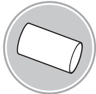
KIT0121003 0158x59mm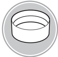
KIT0121006 90°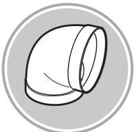
KIT0120991 222x89x1000mm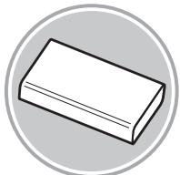
KIT0121001 227x94x80mm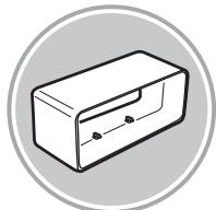
KIT0121004 90° 227 x 288 x 94 mm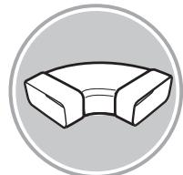
KIT0121005 90° 227 x 94 mm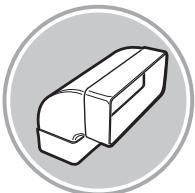
KIT0121008 227x94 - 0153mm
KIT0121010 190x190 - 0147mm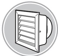
KIT0121009 INT 216X82mm EXT 290X160mm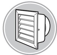
KIT0121002 15° - 227 x 94 mm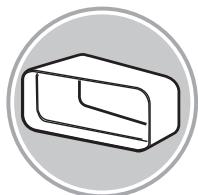
KIT0126810 227x94mm

www.elica.com
www.shop.elica.com

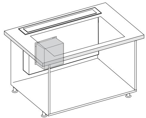
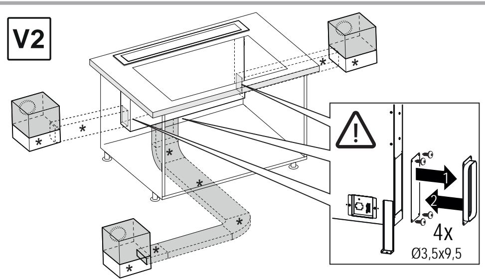
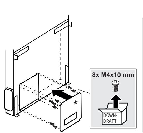
4x03,5x9,5mm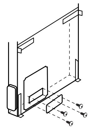



A
2
B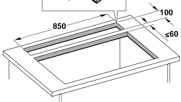

A


3.1
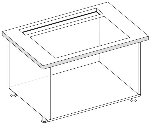
4
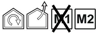
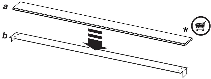

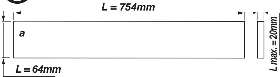
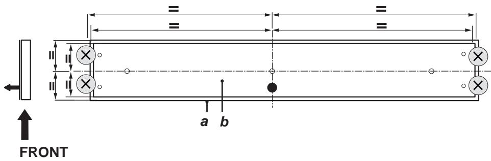




FRONT

BACK
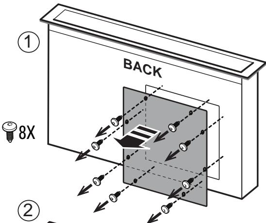
8X
M4 x 10
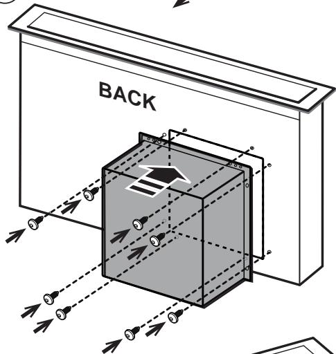
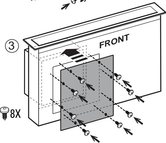
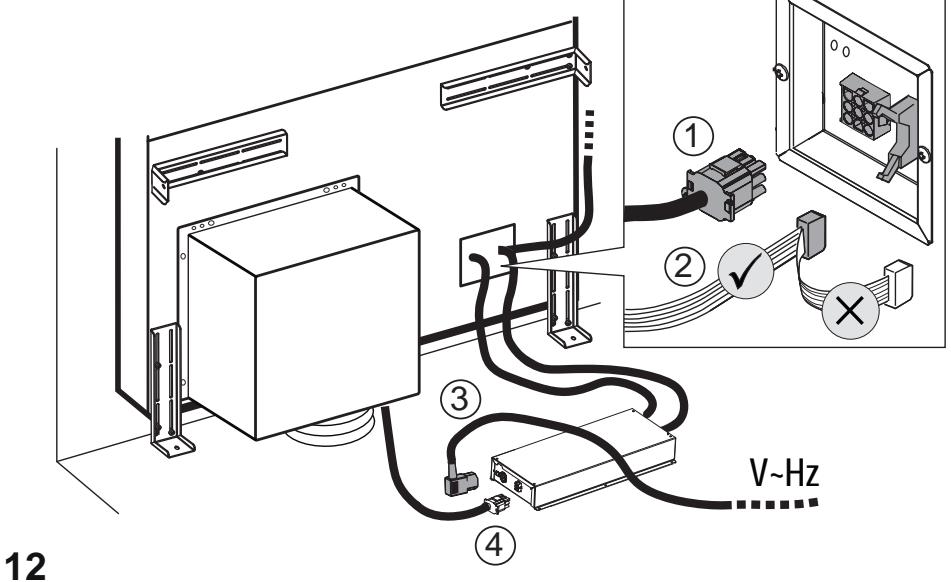

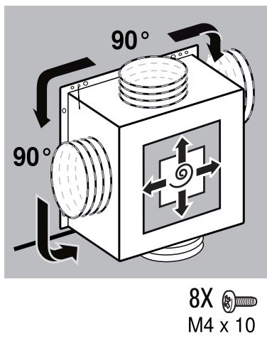
4X M4X10
14.1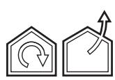

14.2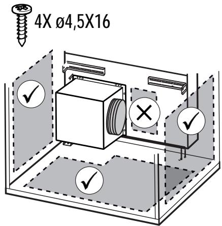


15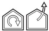
16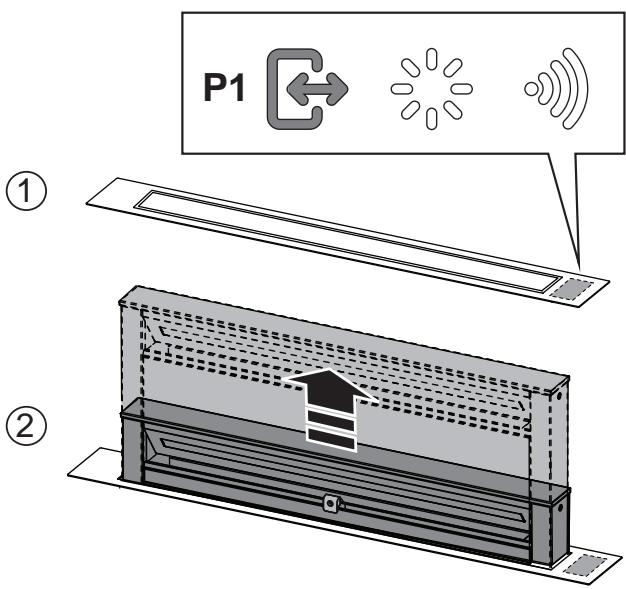





EN "Download the ELICA CONNECT APP to enjoy all the advantages of your connected product. Follow the instructions in the leaflet attached to the product"
EN "You can control your Elica hood with voice commands. Use the ELICA CONNECT APP to discover which voice assistants your hood is compatible with."
Closely follow the instructions set out in this manual. All responsibility, for any eventual inconveniences, damages or fires caused by not complying with the instructions in this manual, is declined. This appliance is intended to be used in household and similar application such as: - staff kitchen areas in shop, offices and other working environments; - farm houses; - by clients in hotels, motels and other residential type environments; - bed and breakfast type environments.
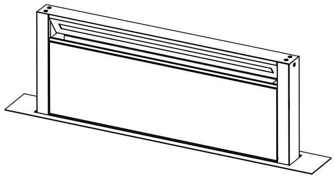
The hood can look different to that illustrated in the drawings in this booklet. The instructions for use, maintenance and installation, however, remain the same.
It is important to conserve this booklet for consultation at any moment. In the case of sale, cession or move, make sure it is together with the product. - Read the instructions carefully: there is important information about installation, use and safety. - Do not carry out electrical or mechanical variations on the product or on the discharge conduits. Before proceeding with the installation of the appliance verify that there are no damaged all components. Otherwise contact your dealer and do not proceed with the installation.
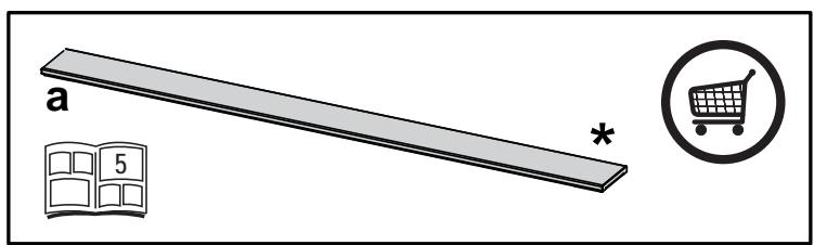
Note: The parts marked with the symbol "(*)" are optional accessories supplied only with some models or otherwise not supplied, but available for purchase.
Caution
- Before any cleaning or maintenance operation, disconnect hood from the mains by removing the plug or disconnecting the mains electrical supply.
- Always wear work gloves for all installation and maintenance operations.
- This appliance can be used by children aged from 8 years and above and persons with reduced physical, sensory or mental capabilities or lack of experience and knowledge if they have been given supervision or instruction concerning use of the appliance in a safe way and understand the hazards involved.
- Children shall not be allowed to tamper with the controls or play with the appliance.
- Cleaning and user maintenance shall not be made by children without supervision.
- The premises where the appliance is
installed must be sufficiently ventilated, when the kitchen hood is used together with other gas combustion devices or other fuels.
- The hood must be regularly cleaned on both the inside and outside (AT LEAST ONCE A MONTH).
- This must be completed in accordance with the maintenance instructions provided. Failure to follow the instructions provided regarding the cleaning of the hood and filters will lead to the risk of fires.
- Do not flambe under the range hood.
- Do not remove filters during cooking.
- For lamp replacement use only lamp type indicated in the Maintenance/Replacing lamps section of this manual.
The use of exposed flames is detrimental to the filters and may cause a fire risk, and must therefore be avoided in all circumstances.
Any frying must be done with care in order to make sure that the oil does not overheat and ignite.
CAUTION: Accessible parts of the hood may become hot when used with cooking appliances.
- Do not connect the appliance to the mains until the installation is fully complete.
- With regards to the technical and safety measures to be adopted for fume discharging it is important to closely follow the regulations provided by the local authorities.
- The air must not be discharged into a flue that is used for exhausting fumes from appliance burning gas or other fuels.
WARNING! Failure to install the screws or fixing device in accordance with these instructions may result in electrical hazards.
- Do not use or leave the hood without the lamp correctly mounted due to the possible risk of electric shocks.
- Never use the hood without effectively mounted grids.
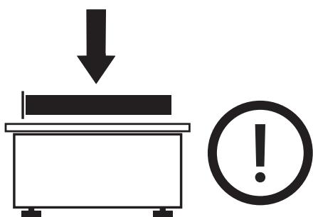
- The hood must NEVER be used as a support surface unless specifically indicated.
- Use only the fixing screws supplied with the product for installation or, if not supplied, purchase the correct screws type.
- Use the correct length for the screws which are identified in the Installation Guide.
- In case of doubt, consult an authorized service assistance center or similar qualified person.
WARNING! Do not use with a programmer, timer, separate remote control system or any other device that switches on automatically.
Electrical connection
The hood must be connected to the mains supply by qualified and trained technicians.
The mains power supply must correspond to the rating indicated on the plate situated inside the hood. If provided with a plug, connect the hood to a socket in compliance with current regulations and positioned in an accessible area, after installation. If it is not fitted with a plug (direct mains connection) or if the plug is
not located in an accessible area, after installation, apply a double pole switch in accordance with standards which assures the complete disconnection of the mains under conditions relating to over-current category III, in accordance with installation instructions.
WARNING! Before re-connecting the hood circuit to the mains supply and checking the efficient function, always check that the mains cable is correctly assembled.
Installation
If the instructions for installation for the gas hob specify a greater distance, this must be adhered to.
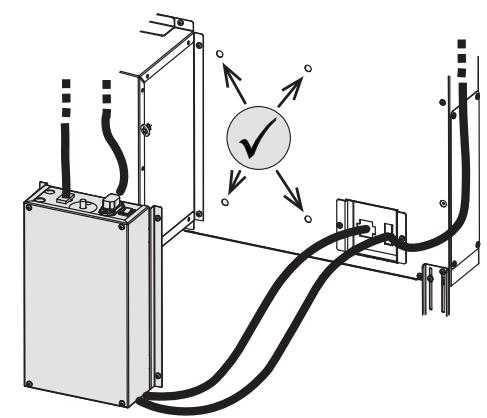
Note: The installation must be performed so that accessibility to the hood and its electronic components is always ensured for possible technical assistance interventions.
Note: the cable that connects the remote motor to the hood is 3 metres long.
Caution! Do not cut the cable between the hood and the engine to avoid losing your right to warranty!
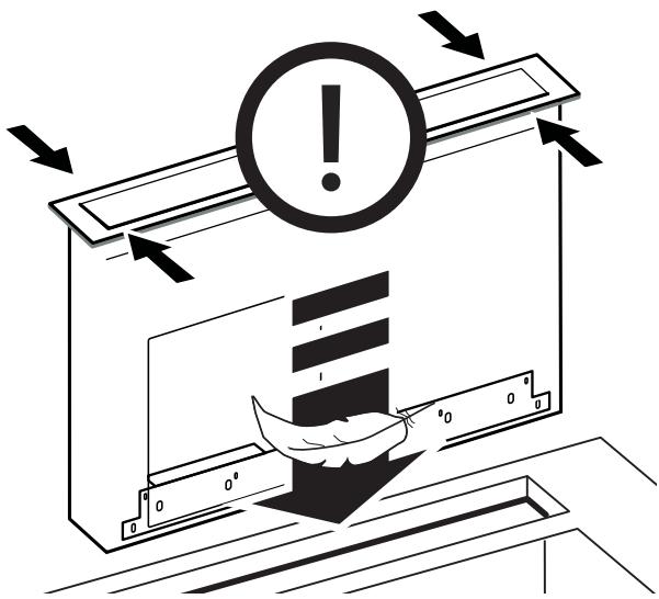
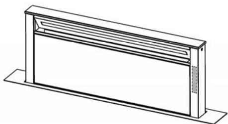
When handling the hood, do not put hands within the range of action of the pull-out suction panel (trolley).
The hood is equipped with safety switches which inhibit operation when the front filter panel is unhooked.
With the intention of constantly improving our products, we reserve the right to make all the changes in their technical, functional or design characteristics, deriving from their evolution. In case of the version with external motor, the normal operation of the hood requires the use of a suction unit (external motor) of the same manufacturer.
When installing the product, it is recommended to keep a minimum distance of 400 mm between the worktop and any components laid on top of the hood.
This is to let the suction panel move upwards (opening) and downwards (closing) without any obstacles, and to facilitate access to the hood controls on the panel.
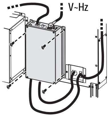
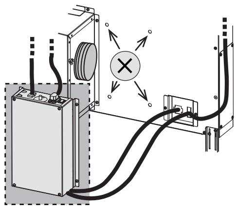
WARNING: Put the metal box containing the electronic components at a distance not shorter than 65 cm from the gas hob or 65 cm from the hood suction point.
RECOMMENDATION: We recommend you to install the metal box containing the electronic components at a distance of at least 10 cm from the ground and sufficiently from all sources of heat (e.g., side of an oven or hob).
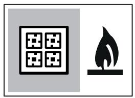
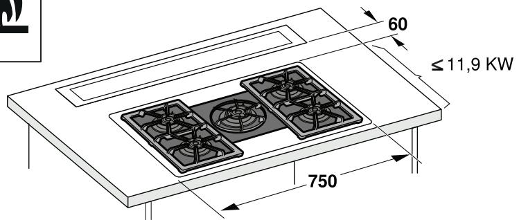
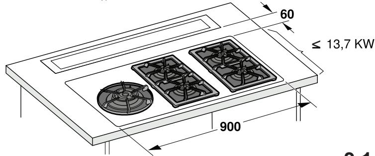
GAS COOKTOP:
All gas cooktops must not exceed the following values:
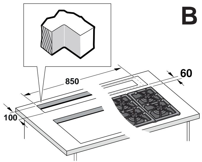
Maximum total power as in fig.3 and max 5 single burners.
A 75cm gas cooktop must not exceed the following values:
Maximum total power 11.9 KW; maximum total power of rear hobs: 4.7 KW; maximum power of wok 4.2 KW. A 90 cm gas cooktop must not exceed the following values: Maximum total power 13.7 KW; maximum total power of rear hobs: 4.7 KW; maximum power of wok 6 KW.
- Range hoods and other cooking fume extractors may adversely affect the safe operation of appliances burning gas or other fuels (including those in other rooms) due to back flow of combustion gases. These gases can potentially result in carbon monoxide poisoning. After installation of a range hood or other cooking fume extractor, the operation of flued gas appliances should be tested by a competent person to ensure that back flow of combustion gases does not occur.
- This appliance is marked according to the European directive 2012/19/EC - UK SI 2013 No.3113 on Waste Electrical and Electronic Equipment (WEEE).
- By ensuring this product is disposed of correctly, you will help prevent potential negative consequences for the environment and human health, which could otherwise be caused by inappropriate waste handling of this product.

- The symbol on the product, or on the documents accompanying the product, indicates that this appliance may not be treated as household waste. Instead it should be taken to the appropriate collection point for the recycling of electrical and electronic equipment. Disposal must be carried out in accordance with local environmental regulations for waste disposal.
- For further detailed information regarding the process, collection and recycling of this product, please contact the appropriate department of your local authorities or the local department for household waste or the shop where you purchased this product.
Appliance designed, tested and manufactured according to:
- Safety: EN/IEC 60335-1; EN/IEC 60335-2-31, EN/IEC 62233. Performance: EN/IEC 61591; ISO 5167-1; ISO 5167-3; ISO 5168; EN/IEC 60704-1; EN/IEC 60704-2-13; EN/IEC 60704-3; ISO 3741; EN 50564; IEC 62301.
- EMC: EN 55014-1; CISPR 14-1; EN 55014-2; CISPR 14-2; EN/IEC 61000-3-2; EN/IEC 61000-3-3; ETSI EN 301 489-1; ETSI EN 301 489-17; ETSI EN 300 328; IEC 62311:2019.
Suggestions for a correct use in order to reduce the environmental impact: Switch ON the hood at minimum speed when you start cooking and keep it running for a few minutes after cooking is finished. Increase the speed only in case of large amounts of smoke and vapor, and use boost speed(s) only in extreme situations. Replace the charcoal filter(s) when necessary to maintain good odor reduction efficiency. Clean the grease filter(s) when necessary to maintain good grease filter efficiency. Use the maximum diameter of the ducting system indicated in this manual to optimize efficiency and minimize noise.
Use
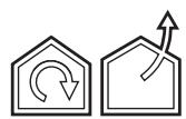
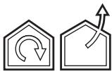
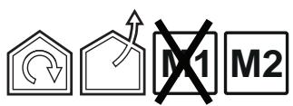
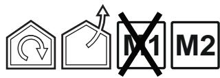
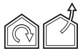
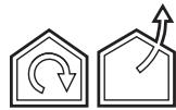
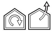
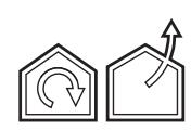
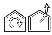
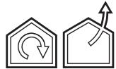
The hood is designed to be used either for exhausting or filter version.

Extraction version
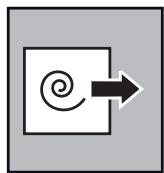
In this case, the fumes are conveyed outside of the building by means of a special pipe connected with the connection ring located on top of the hood.

CAUTION!
The exhausting pipe is not supplied and must be purchased separately.
The diameter of the exhausting pipe must be equal to that of the connection ring.

CAUTION!
If the hood is supplied with an active charcoal filter, then it must be removed.

Filtration version
The aspirated air will be degreased and deodorized before being fed back into the room.
In order to use the hood in this version, you have to install a system of additional filtering based on activated charcoal.
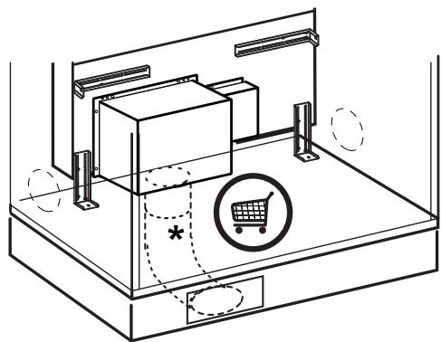
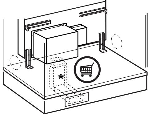
Note: The recycled air in the charcoal filter is sent back to the kitchen through a duct which conveys air to a side of the cabinet.
The models with no suction motor only operate in ducting mode, and must be connected to an external suction device (not supplied).
The connecting instructions are supplied with the peripheral suction unit.
Mounting
Before starting to mount the appliance, make sure that no component is damaged, otherwise contact the dealer and stop mounting. In addition, read all the instructions below carefully.
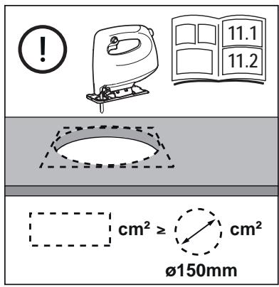
Use an air outlet pipe no longer than 5 metres. - Limit the number of curves in the duct since each curve reduces the suction effectiveness equivalent to 1 linear metre. (E.g.: if two 90° curves are used, the duct should be no longer than 3 metres). - Avoid drastic changes of direction. Use a duct with 150mm diameter constant for the whole length. Use a duct made of standard complying material. - In case of failure to observe the instructions above, the supplier can not be held responsible for capacity or noise problems and no warranty will be granted. - Before making the hole, make sure that the inside of the cabinet, near the hood housing area, does not have the structure of the cabinet or other particulars which may cause problems for the proper installation. Make sure that the overall dimensions of the hood and the hob are compatible with the cabinet and therefore the installation is feasible.
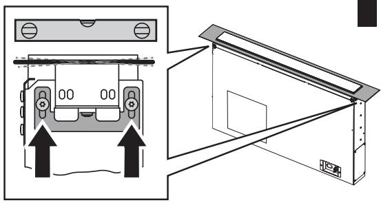
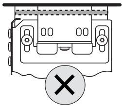
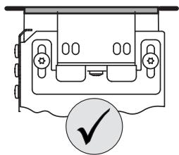
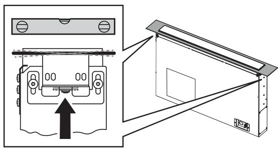
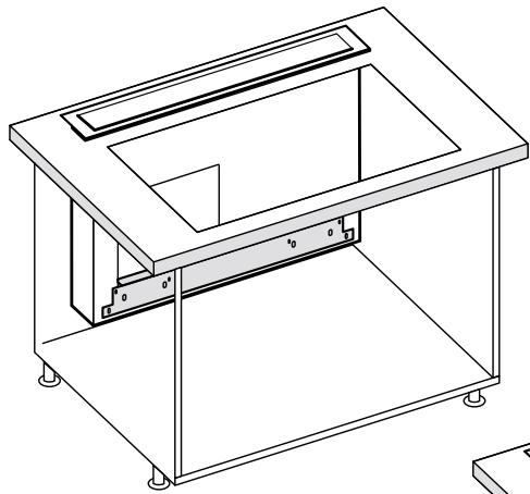
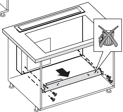
Before inserting the screws into the cabinet, make sure that the product is perfectly perpendicular to the worktop.
Panel Assembly
(only for models where the panel is not supplied with the hood)
CAUTION!
Installation must be carried out only by qualified installers.
FOR THE INSTALLER: Responsibility for installation of the hood, including verification of the conformity of any fixing kit supplied with the product, is the sole responsibility of the installer. Following is a non-exhaustive list of helpful instructions for the installer:
- use a fireproof PANEL (compliant with art. 30 of IEC/EN 60335-2-31), suitable for the operating temperature (at least 80°C ) and humidity (at least 93% ) reached during use;
- total weight of PANEL used should not exceed 1,5kg
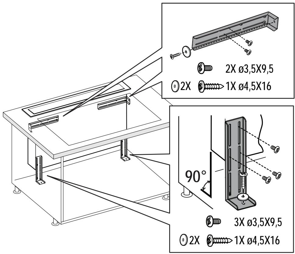
- secure the PANEL to the hood using the fixing points. See the illustrations dedicated to assembly of the panel not supplied with the hood.
- use suitable mechanical parts to fix the PANEL (not included in the assembly kit). Elica denies all liability for damage to persons or property resulting from incorrect installation of the gypsum panels and/or product.
Elica Connect
The hood features a WiFi function for remote connection via the Elica Connect app.
Minimum system requirements:
2.4GHz WiFi b/g/n wireless router, Android or iOS smartphone. Via the stores, check that the app is compatible with the operating system your smartphone is running.
Note: The ELICA manufacturer declares that this model of household appliance with WiFi module radio equipment complies with Directive 2014/53/EU.
The radio equipment operates within the 2.4GHz ISM frequency band, and the maximum radio frequency power transmitted does not exceed 20 dBm (e.i.r.p.).
Warnings:
Data protection. The data that the connected device detects is collected to allow for all the services of the connected appliance to be used. Further information on how the collected data is processed and on the privacy policy is available at www.elica.com. Availability in different countries. The Elica Connect service is available in specific countries. For further information, see the dedicated section at www.elica.com. Future changes. Elica reserves the right to make any changes deemed useful to improve the Elica Connect service. As a result, the descriptions contained in this manual are not binding and should be treated as purely indicative.
Operation
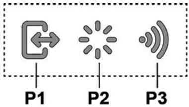
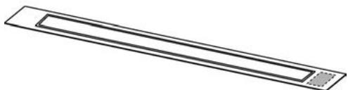
Control Display A
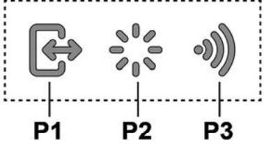
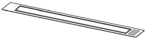
P1. Intake panel opening/closing button P2. Light ON/OFF button P3. WiFi connection button
P1. Intake panel opening/closing button
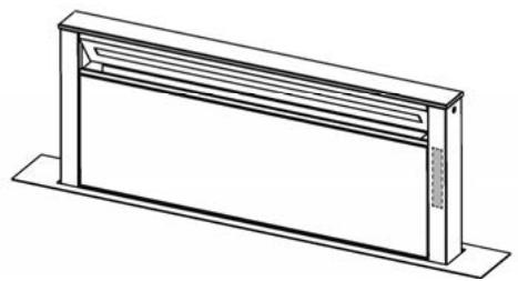
If the panel is CLOSED, by pressing button P1, the hood will turn on and the intake panel will be raised.
This operation will also give access to control display B, which manages motor and lighting.
If the panel is OPEN, by pressing button P1, the hood will turn off and the intake panel will be closed. This operation stops all active motor and lighting functions immediately.
Note: With the panel closed or while it is moving, control display B will remain deactivated. When the panel is completely open, it will be possible to use display B.
P2. Light ON/OFF button
If the panel is CLOSED, by pressing button P2, the hood will turn on, the intake panel will be raised and the lights will turn on only when the pull-out hood is completely open.
If the panel is OPEN, it will only be possible to turn the hood lights on and off.
Note: Light button P2 does not manage Light Dimming and does not turn the hood off.
P3.WiFi button
- WiFi configuration: if the WiFi function is not configured, press for about 2 seconds to enter WiFi configuration mode and follow the instructions on the App to complete the procedure.
During the configuration procedure, the button will light up indicating the connectivity status (see WiFi status table) To interrupt the WiFi configuration procedure, press for about 2 seconds when the button is lit up and is flashing fast.
Once the WiFi function has been configured, if you want to change it, press for about 6 seconds to reset the WiFi
parameters (the button will turn off) and repeat the configuration procedure.
- WiFi activation/deactivation: after the configuration, it is possible to deactivate/activate the WiFi function. Press for about 2 seconds to deactivate/activate the WiFi function.
Deactivating the function does not cause the loss of the WiFi parameters.
WiFi status table
| WiFi button | Device connection status |
| Light off | WiFi not configured or off |
| Light on steady | WiFi connected |
| Light flashing fast | Attempt to connect to the WiFi router |
| Light flashing slowly | Attempt to connect to the Elica cloud |
| Light on with short flashing light | Remote command being received (e.g. engine ignition or light turned on) |
Control Display B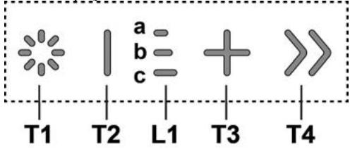
T1. Light ON/OFF button T2. Decrease intake speed / motor off button L1. Speed indicator LED on T3. Motor on / increase intake speed button T4. "BOOST" - intensive speed - function button
T1: Light ON/OFF button
to turn the light on and off.
Press and hold button T1 to increase or decrease the intensity of the light.
T2: Decrease speed / motor off button
Press to decrease the intake power, until the extractor hood is turned off.
Press and hold to turn the hood off directly.
L1: Speed indicator LED on
The central LEDs light up according to the intake speed active/used:
1st speed, LED a will light up
2nd speed, LEDs a+b will light up
3rd speed, LEDs a+b+c will light up
T3: Increase speed button
Press to turn the hood on
Press to increase the intake power.
T4: "BOOST" - intensive speed - function button. Press T4 to activate the intensive intake speed "BOOST 1", timed for 30 minutes
This prolonged timing has been designed to guarantee a suitable cooking time for preparations that release high amounts of smoke during cooking
Note: after the 30 minutes, the hood will go back to the previously set intake speed ***
with the motor on "BOOST 1", press T4 again to activate the intensive intake speed "BOOST 2", timed for 7 minutes
Note: after the 7 minutes, the hood will go back to the previously set intake speed ***
Note: press T4 again, during the 7 minutes, to go back to the previously set intake speed ***
with the "BOOST1" and "BOOST2" functions active, press:
T2 to go back to the previously set intake speed ***
T3 to go back to the 3rd intake speed
*** the previous intake speed remains visible via the indicator LEDs L1
if you have set the intensive speed directly with the hood off, the motor will be turned off after the set time.
While using the "BOOST" functions, the T4 symbol flashes ("BOOST 1": white light - "BOOST 2": blue light)
Filter Saturation indicator lights
At regular intervals, the hood signals the need to perform maintenance on the filters.
LED L1 (a-b-c) on and flashing light (all indicator lights flashing together): perform maintenance on the grease filter.
LED L1 (a-b-c) on and alternating light (the indicator lights turn on in sequence): perform maintenance on the active carbon filter
Note: The filter saturation indicator is visible within the first 10 seconds on turning on the hood; the saturation indicators must be reset within this time.
Reset filter saturation indicator:
Press and hold button T3
LED L1 (a-b-c) turns on and off (depending on the type of filter being reset, the indicator lights flash together or turn on in sequence); an acoustic signal will confirm the reset operation.
Activation of filter saturation indicator
Note: this operation must be performed with the hood off.
- Grease filter
This indicator is normally activated. 1st prolonged press of buttons T3 and T2: if the indicator is active, button T3 turns on; press button T2 to deactivate it. If the indicator is not active, button T2 turns on; press button T3 to activate it.
If the indicator is active, button T3 turns on. Press button T2 to deactivate it. If the indicator is not active, button T2 turns on. Press button T3 to activate it.
- This indicator is normally deactivated. 2nd prolonged press of buttons T3 and T2: if the indicator is active, button T3 turns on; press button T2 to deactivate it. If the indicator is not active, button T2 turns on; press button T3 to activate it.
Note: 3rd prolonged press of buttons T3 and T2.
If the indicator is active, pressing button T2 turns on button T3 to deactivate it. If the indicator is not active, pressing button T3 turns on button T2 to activate it.
Cleaning
Clean using ONLY a cloth dampened with neutral liquid detergent. DO NOT CLEAN WITH TOOLS OR INSTRUMENTS. Do not use abrasive products. DO NOT USE ALCOHOL!
Cleaning
Clean using ONLY a cloth dampened with neutral liquid detergent. DO NOT CLEAN WITH TOOLS OR INSTRUMENTS. Do not use abrasive products. DO NOT USE ALCOHOL!
Grease filter
Traps cooking grease particles.
This must be cleaned once a month (or when the filter saturation indication system - if envisaged on the model in possession - indicates this necessity) using non aggressive detergents, either by hand or in the dishwasher, which must be set to a low temperature and a short cycle.
When washed in a dishwasher, the grease filter may discolor slightly, but this does not affect its filtering capacity.
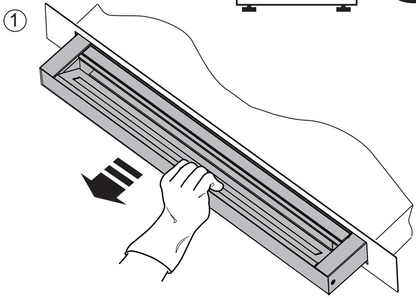
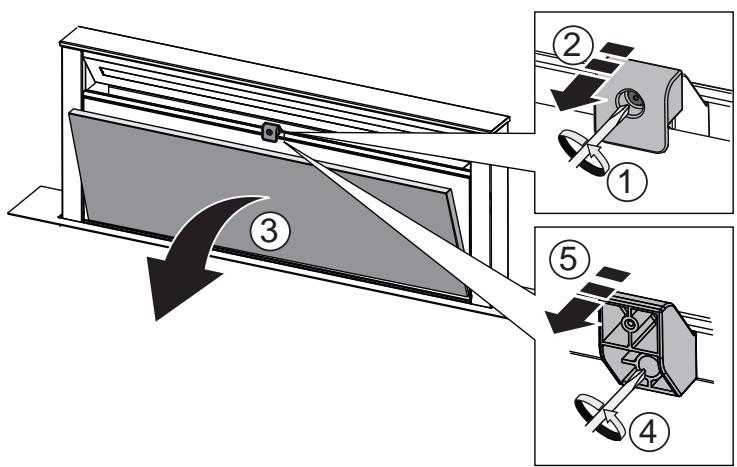
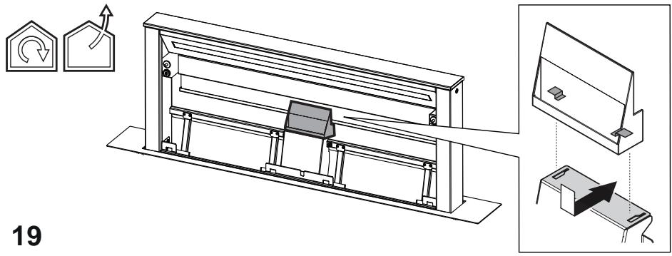
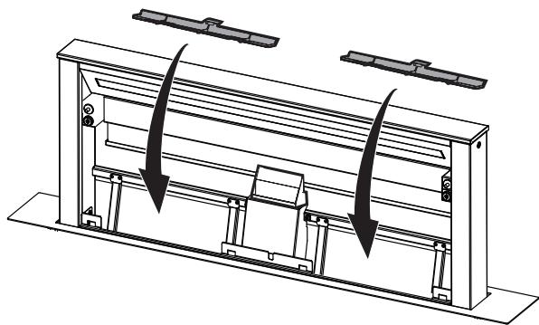
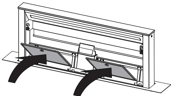
When inserting and removing grease filters and charcoal filters, please make sure that the extractable unit of the hood is in open position.
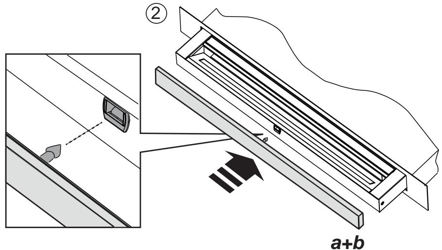
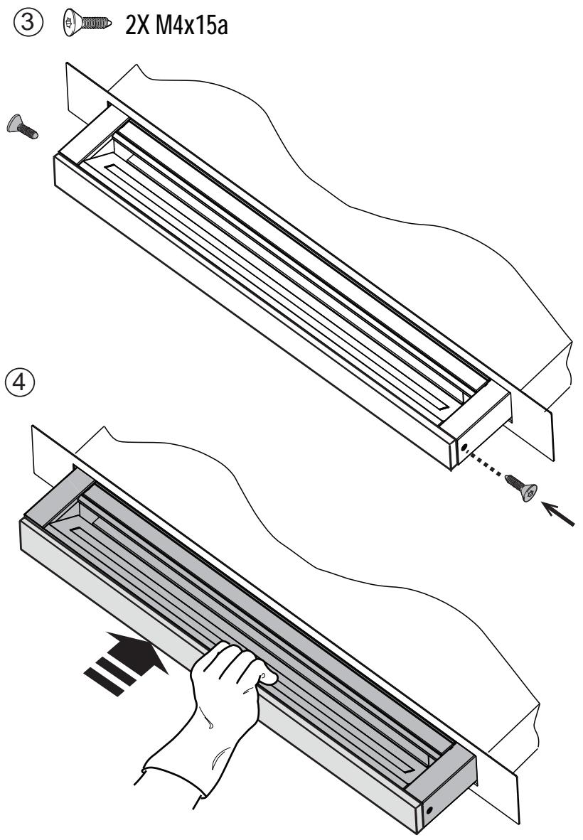
Then remove the front panel, by pulling on the upper part of each side at the same time.
The panel turns forward, so that grease filters can be inserted.
Fig. 18-21
Charcoal filter (filter version only)
It absorbs unpleasant odors caused by cooking.
Washable activated charcoal filter
The charcoal filter can be washed once every two months (or when the filter saturation indication system - if envisaged on the model in possession - indicates this necessity) using hot water and a suitable detergent, or in a dishwasher at 65°C (if the dishwasher is used, select the full cycle function and leave dishes out).
Eliminate excess water without damaging the filter, then put it in the oven for 10 minutes at 100°C to dry completely. Replace the mattress every 3 years and when the cloth is damaged.
After removing the grease filter, it is possible to insert the charcoal filters (not supplied).
Replacing lamps
The hood is equipped with a lighting system based on LED technology.
The LEDs guarantee an optimum lighting, a duration up to 10 times longer than the traditional lamps and allow to save 90% electrical energy.
To replace lights, contact authorised spare part center.
Activating filter saturation indicator
Filter saturation indicator
The indicator is activated automatically after 20 hours of operation. To reset it, press the T3 button. Press the T2 button to deactivate it.
If the indicator is activated, press the T3 button. Press the T2 button to deactivate it. If the indicator is deactivated, press the T2 button. Press the T3 button to activate it.
Display B for command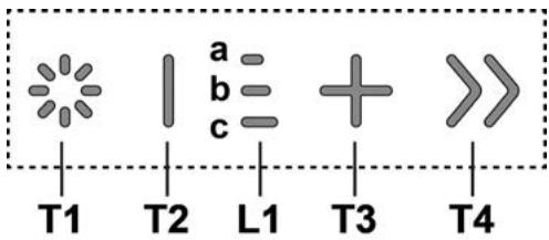
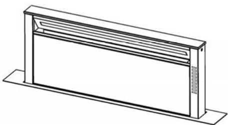
Press to turn on the hood
WARNING: Do not connect the appliance to the mains until the installation is fully completed.
Do not allow children to play with the appliance! Cleaning and maintenance must not be performed by children without supervision. - The room must be adequately ventilated when the hood is used simultaneously with appliances burning gas or other fuels. - The hood must be cleaned frequently, both internally and externally (at least once a month). - Follow the maintenance instructions in the manual! - Failure to follow the instructions for cleaning the hood and for cleaning or replacing the filters may result in a fire hazard. - Strictly forbidden is the preparation of flambé dishes under the hood. To replace the lamps, use only those specified in the section "Replacing the lamps", as specified in this instruction manual. The use of open flames is harmful to the filters and may cause a fire, so it must be avoided at all times. The preparation of fried food must be done under supervision, as overheated oil may ignite. ATTENTION: When the hood is in operation, the accessible parts may become hot. Do not connect the appliance to the mains until you have completed the installation.
- All parts of the technical data and safety measures that must be taken for the discharge of fumes and vapors, and in accordance with the regulations, must be strictly followed as prescribed by the competent local authorities.
- The extracted air must not be discharged into a flue used for exhausting fumes from appliances burning gas or other fuels. ATTENTION! Failure to install the screws or fixing devices in accordance with these instructions may result in electrical hazards. Do not use or leave the hood without the correctly mounted lamps, as there is a risk of electric shock.
- Never use the hood without the correctly mounted grid!
- The hood must never be used as a support surface unless this is specifically indicated.
- When mounting, use only the screws supplied with the device. If they are missing, purchase suitable screws. Use screws of the appropriate length, as indicated in the installation instructions.
- If replacement of the lamp is required, contact the authorized service for technical maintenance by qualified personnel.
WARNING! Do not use the programmer, timer, remote control, or any other device that activates automatically.
! Electrical connection
The connection to the electrical mains of the hood must be carried out by qualified and specialized technical personnel.
The mains supply must correspond to the rating indicated on the data plate of the hood, located on its inner side. If it is equipped with a plug, connect the hood to a socket that complies with current regulations and is accessible after installation. If it is not equipped with a plug (direct connection to the mains), or if the plug is not accessible after installation, use a bipolar switch with a contact opening of at least 3 mm, in compliance with installation rules.
WARNING! Before connecting the hood to the mains and checking that it functions properly, verify that the cable is installed correctly.
Installation
If the instructions for the gas cooking appliance specify a distance, then it must be
respected.
Warning: Installation must be carried out in such a way as to ensure access to the hood and electrical components for any necessary technical maintenance. Warning: The cable that connects the hood to the mains must be
WARNING! Do not connect the hood's power cable to the motor, so as not to lose the right to warranty.
During operation of the hood, do not place your hands in the area of action of the suction or near the internal mechanism.
The hoods are equipped with safety switches that stop their operation when the filter or front panel is removed.
In an effort to constantly improve our products, we reserve the right to make changes to the technical and functional characteristics of the devices, as well as to their aesthetic appearance, which are part of their continuous evolution. For models with external motor, for the correct functioning of the hood, the height of the suction unit (external motor) must be installed with the chimney.
Install the appliance at a minimum distance of 400 mm. The distance between the working plate and the ventilation components, located above the aspirator.
Make sure you have sufficient clearance when moving the hood up (opening) and lowering the hood (closing) of the aspirating panel, and this clearance should be sufficient to reach the commands of the aspirator, located on the panel.
WARNING: Insulate the metal duct and electrical components at a distance of no less than 65 cm from the gas pipe, or in any case, 65 cm from the aspirating grid.
RECOMMENDATION: We recommend that you install the metal duct and electrical components at least 10 cm away from the surface and at a sufficient distance from any heat source (for example: the side of the gas hob or the gas stove).
GAS STOVE TYPE:
For gas hobs, the following values must be observed: Maximum total power as indicated on the label. Max. 5 burners. For gas stoves from 75 cm, the following values must be observed:
Maximum total power: 11.9 kW; Maximum power for gas burners: 4.7 kW; Maximum power for wok: 4.2 kW. For gas stoves with a width of 90 cm, the following values must be observed:
Maximum total power: 13.7 kW; Maximum power for gas burners: 4.7 kW; Maximum power for wok: 6 kW.
This product complies with the requirements of:
- European Directive 2012/19/EC - UK SI 2013 No.3113
- Waste Electrical and Electronic Equipment (WEEE).
Ensure that this product is recycled separately to protect the environment and your health.

The symbol on the product or its documentation indicates that this product must not be treated as household waste, but must be handed over to the appropriate collection point for the recycling of electrical and electronic equipment. Please contact your local authorities for information on waste disposal. For more information about the recycling of this product, please contact your local waste collection service or the store where you purchased this product.
Type of product, country of origin and manufactured in accordance with:
- Safety: EN/IEC 60335-1; EN/IEC 60335-2-31, EN/IEC 62233.
- Performance characteristics: EN/IEC 61591; ISO 5167-1; ISO 5167-3; ISO 5168; EN/IEC 60704-1; EN/IEC 60704-2-13; EN/IEC 60704-3; ISO 3741; EN 50564; IEC 62301.
- EMC - Electromagnetic compatibility: EN 55014-1; CISPR 14-1; EN 55014-2; CISPR 14-2; EN/IEC 61000-3-2; EN/IEC 61000-3-3; ETSI EN 301 489-1; ETSI EN 301 489-17; ETSI EN 300 328; IEC 62311:2019.
Recommendations for correct use to reduce the impact on the environment: Turn on the hood at minimum speed when you start cooking and let it run for a few minutes after cooking is finished. Increase the speed only in case of large amounts of fumes and vapors. Increase the speed only in extreme situations. Replace the filter/filters with active carbon when necessary to maintain good odor absorption efficiency. Clean the grease filter/filters when necessary to maintain good grease filter efficiency. Use the maximum diameter of the air exhaust system, specified in this manual, to optimize efficiency and reduce noise.
Use
Hood with motor or without motor: It extracts and filters the air through the filters, while simultaneously recirculating it.

Extraction version
The air is exhausted outside through an air duct.
It must be connected to the ventilation duct.
WARNING!
The air duct is not included with the hood and must be purchased separately.
The appliance must be connected to the mains in accordance with the requirements.
WARNING!
If the appliance is equipped with an active carbon filter, the air must be discharged outdoors.

Extraction mode with recirculation
The extracted air is conveyed through the duct to be discharged outdoors through the wall. To use the appliance in this operating mode, it is necessary to install the additional recirculation filter system on the active carbon filter.
Note: The air that is recirculated from the active carbon filter is discharged back into the room through the air duct, which is located on the upper side of the appliance.
Models without extraction: The motor is designed to operate only in the recirculation mode. The appliance must be connected to a permanently recirculating unit, which is purchased separately.
The instructions for connection are supplied together with the peripheral recirculation unit.
INSTALLATION
Before starting the installation of the device, check the data and the components of the device. If any are missing, contact the supplier and stop the installation. Read all the instructions carefully.
- The air duct must be installed with a maximum length of 5 m. Pay attention to the minimum number of bends in the duct, as each bend reduces the duct capacity by 1 linear meter (for example: if there are 2 bends with a 90° angle, the length of the duct must not exceed 3 m.). Do not change direction abruptly.
- Use ducts with a diameter of 150 mm for the air flow. The material from which the ducts are made must comply with the applicable standards.
- In case of non-compliance with the installation instructions, the supplier company assumes no responsibility for any problems in the operation or for an increase in noise, and consequently provides no warranty. Before making the hole, make sure that on the other side of the wall, where the appliance will be installed, there is no structure or other elements that could obstruct the installation of the appliance. Make sure that the dimensions of the appliance and the hob are compatible and that there is no obstacle for installation. - Place the screws in the wall, make sure that the device is positioned perpendicular to the work surface.
will be installed the appliance, do not damage the structure of the wall or other elements that could obstruct the installation of the appliance. Make sure that the dimensions of the appliance and the hob are compatible and that there is no obstacle for installation. - Place the screws in the wall, make sure that the device is positioned perpendicular to the work surface.
Installation of the panel
(for models where the aspirator is not supplied)
WARNING!
The aspirator must be installed only by qualified personnel. For the installer: read the installation instructions for the aspirator, including the check of the fixing kit compliance, which may be included with the product. In the following, only the essential information for the installer is presented.
The panel must comply with IEC/EN60335-2-31, suitable for the operating temperature (up to 80°C) and humidity (up to 93%) of the appliance; - the total weight of the panel must not exceed 1.5 kg; - fix the panel to the aspirator using the fixing screws. See the illustrations for the installation of the panel, which is not supplied with the aspirator. - For fixing the panel, use suitable mechanical components (if not included in the installation kit). If you open any responsibility for the safety of the panel or the product, in case of incorrect installation of the panel and/or the product.
Elica Connect
Connect the device with WiFi function for remote control via the Elica Connect app.
Minimum system requirements:
2.4GHz WiFi b/g/n router, Android or iOS smartphone. Check the app stores for compatibility of the app with the operating system version of your smartphone.
Note: The manufacturer ELICA declares that this model of kitchen hood with WiFi radio equipment is in compliance with Directive 2014/53/EC.
The radio equipment operates in the frequency range of 2.4GHz, maximum transmitted radio frequency power does not exceed 20 dBm (e.i.r.p.).
Precautions:
Data protection. The data collected by the device are processed to allow the use of all functions connected to the device. For more information on how the collected data are processed, you can visit the website www.elica.com. Availability of the service. The Elica Connect service is offered in certain countries. For more information, visit the dedicated section of the website www.elica.com. Changes. Elica reserves the right to make any changes it deems useful for improving the Elica Connect service. Therefore, the descriptions and references in this manual are not binding and have indicative value.
Instructions for use
Control display

P1. Button for opening/closing the suction panel. P2. Light ON/OFF button P3. WiFi connection button
P1. Button for opening/closing the extraction flap
If the flap is CLOSED, by pressing button P1 the extractors will turn on and the extraction flap will open.
This operation will give access to the command that controls the motor and the lighting.
If the flap is OPEN, pressing button P1 will close the flap, which will close the extraction flap. This operation will immediately stop all active motor functions and lighting.
Note: When the flap is closed and the device is off, the control panel will remain off. When
the flap is fully open, it will be possible to use the panel.
P2. Light button ON/OFF
If the flap is CLOSED, by pressing button P2 the extractors will turn on, the extraction flap will open, and the lights will turn on, but only when the damper is fully open.
If the flap is OPEN, it can be controlled only by turning the extractor lighting on and off.
Note: The light button P2 does not control the dimming of the lights and does not control the extraction from the extractor.
P3. WiFi button
- WiFi configuration: If the WiFi function is not configured, press for about 2 seconds to enter WiFi configuration mode and follow the instructions in the application to complete the procedure.
During the configuration procedure, the button lights up, showing the connection status (see the WiFi status table).
To exit the WiFi configuration procedure, press for about 2 seconds when the button light is flashing.
If the WiFi function is already configured and you want to change it, press for about 2 seconds to reset the WiFi parameters (the button will turn off) and repeat the configuration procedure.
- To activate/deactivate the WiFi function, press and hold for about 2 seconds. Deactivating the function will not lead to loss of WiFi parameters.
Status table WiFi
| Бутон WiFi | Стачс Врьзka усточтvo |
| Изклочena СBVТПИна | WiFi не в КONDФигүріран илі виклочen |
| Постоанно ВКЛочena СBVТПИнa | WiFi сbvрэан |
| Мiraшиа бърза СBVТПИнa | Опит за сbvрзвае с рутет WiFi |
| Мiraшиа Bavна СBVТПИнa | Опит за сbvрзвае с cloud Elica |
| Вклочен Индікаторс Краты мiraшиа СBVТПИнa | Прочемане с дисцantoно уразWIЕпe (нарр. Залалвае на моторі піи OCBETПЕнe) |

T1. Button light ON/OFF T2. Button speed decrease / motor off L1. LED indicator for speed activation T3. Button motor on / speed increase T4. "BOOST" function - intensive speed - T1: Button light ON/OFF
To turn the light on and off.
By pressing and holding button T1, it is possible to increase / decrease the light intensity.
T2: Button speed decrease / motor off
Press to decrease the suction power, until the vacuum cleaner turns off.
Press and hold to turn off the vacuum cleaner directly.
L1: LED indicator for speed activation
The central LED indicator lights up based on the speed at which the vacuum cleaner is activated:
1 speed: blue LED indicator a 2 speed: blue LED indicator a+b 3 speed: blue LED indicator a+b+c
T3: Button for increasing speed
Press to turn on the vacuum cleaner.
Press to increase the suction power.
T4: "BOOST" function button - intensive speed
Press T4 again to activate the intensive aspiration speed "BOOST1", with a timer for 30 minutes.
This increased temperature is created to guarantee a one-time period, useful for cooking with high smoke emission.
Note: after 30 minutes, the aspirator will not return to the previously set aspiration speed***
After the motor is turned on in "BOOST 1", press T4 again to activate the intensive aspiration speed "BOOST 2", with a timer for 7 minutes. Note: after 7 minutes, the aspirator will not return to the previously set aspiration speed. *** Note: Press T4 again, during the 7th minute, it will return to the previously set aspiration speed***
During the "BOOST1" and "BOOST2" functions being active, press:
T2 returns to the aspiration speed set previously ***
.....T3 returns to the 3rd aspiration speed ***The speed of the previous aspiration remains with the possibility for visualization via LED indicators for visualization L1
If the intensive speed is set directly from the switched off aspirator, after the set time has elapsed, the motor switches off.
During the use of the "BOOST" functions, the symbol T4 lights up
("BOOST 1": 6 lights - "BOOST 2": 7 lights)
Filter saturation indicator
On the periodic intervals, the aspirator indicates the need to clean or replace the filter.
The LED indicator L1 (a-b-c) is lit with a steady light (all indicator lights are on together): clean the grease filter.
The LED indicator L1 (a-b-c) is lit with a flashing light (the indicator lights turn on sequentially): clean the filter with activated charcoal.
Note: The filter saturation indication is active for the first 10 seconds after turning on the aspirator, during this time the filter saturation indicators are reset.
Filter indicator for replacement:
Press and hold button T3
The LED indicator L1 (a-b-c) ① lights up (depending on the filter type, the filter replacement reset is performed, the indicator lights up briefly and then goes out sequentially); ② an audible signal for correct filter reset is emitted.
Activating the filter replacement indicator
Note: This operation is performed with the appliance switched on.
- Oil filter
The indicator is normally activated 1° by pressing and holding buttons T3 and T2
If the indicators are activated, press button T3, then button T2 to deactivate them; if the indicators are deactivated, press button T2, then button T3 to activate them.
- Carbon filter
The indicator is normally deactivated 2° by pressing and holding buttons T3 and T2
If the indicators are activated, press button T3, then button T2 to deactivate them; if the indicators are deactivated, press button T2, then button T3 to activate them.
Note: 3° pressing and holding buttons T3 and T2 resets the settings menu.
Cleaning
Cleaning
For cleaning, use ONLY a cloth dampened with neutral detergent. DO NOT use tools or appliances for cleaning!
Use the preparation, concentrate as directed. DO NOT USE SPIRITS!
Filter for the machine
The filter retains parts, separated during operation.
To be sure, use only the indicator for saturation of the filter (it is described in case you have purchased a model equipped with such an indicator).
Use not too much detergent and clean the machine regularly, but at low temperature and short washing cycle.
Using the filter in the dishwasher is possible to disinfect, but this in no way replaces the need to filter.
Installation and removal of the filter for the machine is carried out by opening the front panel with tools.
After this, remove the panel as shown in the figure and simultaneously from both sides. The panel is removed forward, leaving access to the filter for the machine.
Fig. 18-21
Filter with active carbon (for self-filtering version)
The inlet nozzles, which are separated during pressing, are retained.
When the active carbon is exhausted
The filter with active carbon can be used for every one to two months or when the indicator for saturation of the filter (if your model is equipped with one) shows it. Use only suitable detergent for the dishwasher and at 65°C. In this case, the dishwasher does not need any other care; it must be run on a washing cycle only.
Rinse thoroughly with water, after placing it in the container for about 10 minutes at 100°C
The textile gaskets of the filter must be replaced every three years or if the surface is damaged.
The hood is designed to be used in extraction mode, and it is possible to install the hood with an activated carbon filter (if not supplied with the aspirator).
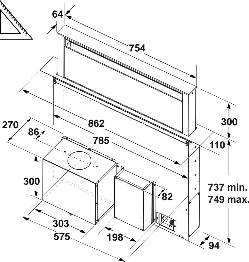
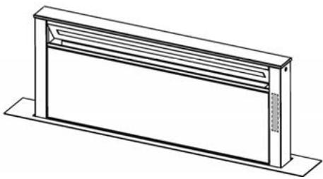
Hood dimensions
The aspirator is equipped with a lighting system with LEDs.
The LEDs guarantee optimal lighting, up to 10 times more powerful than traditional lamps and allow 90% energy savings.
To replace the lamps, contact the after-sales service for spare parts.
The device has been designed, tested and manufactured in accordance with:
- Safety: EN/IEC 60335-1; EN/IEC 60335-2-31, EN/IEC 62233.
- Operational characteristics: EN/IEC 61591; ISO 5167-1; ISO 5167-3; ISO 5168; EN/IEC 60704-1; EN/IEC 60704-2-13; EN/IEC 60704-3; ISO 3741; EN 50564; IEC 62301. EMC: EN 55014-1; CISPR 14-1; EN 55014-2; CISPR 14-2; EN/IEC 61000-3-2; EN/IEC 61000-3-3; ETSI EN 301 489-1; ETSI EN 301 489-17; ETSI EN 300 328; IEC 62311:2019.
Suggestions for correct use to reduce impact on the environment: Turn on the hood at minimum speed when you start cooking and leave it running for a few minutes after you finish cooking. Increase speed only in case of a large amount of smoke and use higher speeds only in extreme situations. Replace the charcoal filter(s) when necessary to maintain good efficiency in reducing odors. Clean the grease filter(s),
when necessary, to maintain good efficiency of the grease filter. Use the maximum diameter of the air exhaust system indicated in this manual for optimal efficiency and minimal noise level.
Use
The hood is designed for operation in air extraction mode or in air recirculation mode.

Using the hood in air extraction mode
In this mode, the fumes are discharged outside through the pipes connected to the connecting ring.

ATTENTION!
The exhaust pipe is not included in the kit and must be purchased separately.
The diameter of the exhaust pipe must match the diameter of the connecting ring.

WARNING!
If the hood is equipped with a charcoal filter, make sure to remove it.

Use of recirculation
air
The air must be filtered through a charcoal filter before being recirculated into the room. The air is drawn in and then returned to the room through the top grille.
Usage: Air purified by the charcoal filter is returned to the kitchen through the air outlet, which draws air through one of the side panels of the kitchen unit.
Models without a motor block can operate in one mode: air exhaust to the outside. Therefore, they must be connected to an external exhaust system (not included in the supply).
The instructions for use are supplied with the exhaust unit.
Installation
Before starting installation, check that all components are not damaged; if they are, contact the point of sale before proceeding with installation. Also, carefully read all instructions supplied with the appliance.
Use an exhaust pipe no longer than 5 meters. Limit the number of bends in the duct, as each bend reduces the suction efficiency by approximately 1 linear meter. (Example:
If a 90° bend is used, the duct length must not exceed 3 meters).
- Avoid sharp changes in direction. Use a duct with a diameter of 150 mm along its entire length. Use a duct made of material approved by standards. In case of failure to follow the above instructions, the manufacturer is not responsible for problems with suction power or noise and does not provide a warranty.
- Before drilling the hole, check that there is no wall structure or other parts behind the wall in the installation area of the hood that could interfere with proper installation.
Check that the overall dimensions of the hood correspond to the dimensions of the kitchen furniture, and therefore the possibility of performing the installation.
- Before inserting the flue into the hood, check that the product is perpendicular to the surface.
Flue installation
(Only for models where the flue is not supplied with the hood)

WARNING!
Installation must be carried out only by qualified technicians. FOR THE INSTALLATION TECHNICIAN: Responsibility for the installation of the hood, including verification of compliance of the fastening kit, if supplied with the product, lies with the installer. Below are some examples and non-exhaustive guidelines for the technician on installation:
Use a flue of the appropriate type (in accordance with the requirements of IEC/EN 60335-2-31), suitable for the operating conditions of temperature (not less than 80°C) and humidity (not less than 93%), achievable in the application: - The weight of the flue used must not exceed 1.5 kg; - Secure the flue to the hood at the fixing points. See the flue installation instructions, if not provided with the hood. - Use flue fasteners that are suitable for the mechanical elements (not included in the installation kit). The company Elica disclaims all liability for damage caused to persons or property as a result of incorrect installation of the flue and/or the product.
Elica Connect
The hood is equipped with a WiFi function for remote connection via the Elica Connect app.
Minimum system requirements:
Wireless router 2.4 GHz WiFi standards b/g/n Smartphone/tablet. Check the app stores for compatibility of the app with the operating system of your smartphone.
Required information:
Data processing and protection. Data collected by the connected device is used to ensure the proper functioning of all functions of the purchased appliance. More detailed information on the use of collected data and the privacy policy notice is available on the website www.elica.com. Availability in different countries. The Elica Connect service is available in certain countries. More details can be found in the specific section of the website www.elica.com. Future modifications. The company Elica reserves the right to make all changes deemed necessary for the improvement of the Elica Connect service. Therefore, the descriptions provided in this user manual are not binding and are for informational purposes only.
Operation
Press and hold the power button until it turns off, then release it.
Press and hold, then immediately release the extraction lever.
L1: Indicator lights - switch on speed
Central indicator lights turn on depending on the current/used speed of extraction:
Speed 1 - indicator light a; speed 2 - indicator lights a+b; speed 3 - indicator lights a+b+c
T3: Speed increase button
Press the button to increase extraction power.
Press to increase extraction power.
T4: "BOOST" function button - increased speed levels -
Press button T4 to enable increased extraction speed "BOOST 1", which will be active for 30 minutes.
This function is intended to ensure sufficient time for cleaning or processing large quantities of materials.
Note: After 30 minutes, the extraction speed will return to the value set previously ***
While the device is operating in "BOOST 1" mode, press button T4 again to enable increased extraction speed "BOOST 2", set for a working time of 7 minutes.
Note: After 7 minutes, the extraction speed will return to the value set previously ***
Note: If button T4 is pressed again within the 7-minute interval, the extraction speed will return to the level that was set previously ***
The "BOOST1" and "BOOST2" functions are active when pressed:
T2 returns to the previously set speed ***
T3 returns to the 3rd speed of the exhaust *** On the previous speed of the exhaust, the indicators L1 continue to indicate
If the set speed is exceeded with the exhaust valve closed, then after the corresponding interval has elapsed, the engine switches off.
When using the "BOOST" function, the symbol T4 flashes ("BOOST 1": white light - "BOOST 2": blue light)
Filter clogging indicators
After certain time intervals, the exhaust valve signals the need to perform maintenance of the filters.
CUN L1 (a-b-c) lights up with a flashing light (all indicators - blue - flash together): perform maintenance of the washable filter.
CIVL L1 (a-b-c) lights up alternately (the indicators light up sequentially): perform maintenance of the filter with activated carbon.
Note: The filter clogging indication appears the first 10 seconds after switching on the exhaust valve. During this interval, the clogging indicators must be reset.
Reset of filter clogging indication:
Press and hold the T3 button
CIV L1 (a-b-c) lights up and goes out (depending on the type of filter for which the indication reset is performed, the indicators flash together or light up alternately); an acoustic signal sounds to confirm correct execution of the reset.
Switching on the filter clogging indicator
Note: The operation is performed with the exhaust switched off.
The device must be under control and must not be played with.
Cleaning and maintenance operations must not be performed without supervision.
The device must have sufficient ventilation when the hood is used simultaneously with other appliances that operate on gas or other fuels.
- The hood must be cleaned frequently, both inside and outside (at least once a month), and maintained in accordance with the maintenance instructions.
Failure to observe the cleaning rules for the hood and filters increases the risk of fire.
It is strictly forbidden to cook with an open flame under the hood.
For lighting, only use the lamps specified in the maintenance/replacement of the LED lamp section.
Using an open flame can damage the filters and may lead to fire, so it must be avoided in any case.
Installation must be carried out by qualified personnel to avoid any risk of electric shock.
WARNING: When the cooking surface is in operation, accessible parts may become hot.
Do not connect to the electrical supply until the installation is completely finished. This applies to technical measures and safety measures during use.
When connecting to the mains, strictly observe the standards of the competent local authorities.
The air extracted must not be discharged into a flue used for exhaust fumes from appliances operating on gas or other fuels.
WARNING! Failure to install the appropriate screws and devices in accordance with these instructions may result in a risk of electric shock.
Do not use or fill the socket without properly installed lamps with a risk of electric shock.
- Never use the socket without a properly installed grille.
- The socket must never be used as a support surface until it is switched on.
Use the screws for fixing in the set with the product of this installation, which are included in the set, to attach the screws of the correct type.
Use the correct type of screws as indicated in the installation manual.
- In case of doubt, consult the authorized service center or qualified personnel.
WARNING! Do not use with a programmer, timer, separate remote control or any other device that turns on automatically.
The exhaust pipe is not supplied and therefore must be purchased separately.
The diameter of the exhaust pipe must match the diameter of the existing ring.

WARNING!
Since the exhaust hood cover has carbon filters, they must be removed.

Version with recirculation filter
Remove the protective film and dust and then return to the room. To use the cover in this mode, it is necessary to install a filter system with activated carbon.
Note: Filtering through an activated carbon filter is required before the air can exit through one side of the housing.
Hood models without a motor block can only operate in one air exhaust mode, so they must be connected to an external exhaust installation (not included in the supply).
The instructions for installation and connection are given in the attached manual.
Installation
Before starting the installation of the device, make sure that all components are not damaged, and in the opposite case, contact the point of sale and do not proceed with the installation. Also, carefully read all the instructions provided with the device.
Use an exhaust air duct with a maximum length that does not exceed 5 meters. - Avoid too many bends in the exhaust air duct, as each bend reduces the efficiency of the hood, so it is recommended to use 1 meter per bend. (Example: if you use 2 bends of 90°, the length of the exhaust duct must not exceed 3 meters in length). - Avoid sharp changes in direction. Use a duct with a diameter of 150mm along the entire length. Use a duct made of certified material. - If the above instructions are not followed, the supplier is not responsible for any problems or damages, and no warranty will be provided. - Before making the hole, check that inside the housing, in the area of the installation, there are no structural elements or other parts that could cause problems for proper installation. Make sure that the dimensions of the hole correspond to the available space in the furniture installation. - Before tightening the screws, make sure that the product is positioned absolutely perpendicular to the work surface.
PANEL INSTALLATION
(For models where the panel is not supplied with the hood)
WARNING!
The installation must be carried out by qualified personnel. For installers: responsibility for the installation of the hood, including checking the compliance of the hood kit, which may be included in the supply, lies with the installer. The data given are indicative and not binding; some instructions useful for the installer's work:
Use a panel of the resistant type (according to standard EN 60335-2-31), which is suitable for the operating conditions of temperature (not less than 80°C) and humidity (not less than 93%), which are reached during use; - the total weight of the panel used must not exceed 1.5 kg - Fix the panel to the hood using thin fasteners. See the illustration, showing the installation of the panel, where it is not supplied with the hood. - For fixing the panel, use the appropriate mechanical components (not included in the hood kit). The manufacturer declines all responsibility for damage, injury, or damage resulting from incorrect installation of the hood and/or the panel.
Elica Connect
The hoods are equipped with WiFi for remote connection via the Elica Connect app. Minimum system requirements:
- Wireless router 2.4 GHz WiFi standards b/g/n Smartphone with Android or iOS. Check on the website the compatibility of the app with your smartphone's operating system.
Manufacturer: Elica Group - This model of household electric appliance complies with Directive 2014/53/EU. The radio system operates in the 2.4 GHz ISM frequency band. The transmitted radio power does not exceed 20 dBm (e.i.r.p./equivalent isotropically radiated power).
Precautions:
Data processing and protection. Data collected by the appliance is used to ensure the operation of all functions of the household electric appliance. Detailed information on the use of collected data and notifications about the possibility of deactivation is available on the website www.elica.com. Availability varies by country. The Elica Connect service is available in some countries. More details can be found in the specific section of the website www.elica.com. Possible modifications. Elica Group reserves the right to make all changes deemed necessary for the improvement of the Elica Connect service. Therefore, the descriptions provided in this manual are not binding and are indicative.
Ensure sufficient time, necessary for
Cleaning the hood creates a large amount of
Note: After 30 minutes, the hood will return to the previously set speed ***
If the hood is operating in "BOOST 1" mode, press T4 once to switch to "BOOST 2" and the hood will operate at this speed for 7 minutes
Note: After 7 minutes, the hood will return to the previously set speed ***
Note: If T4 is pressed again within the 7-minute interval, the hood speed will return to the level set before ***
When the "BOOST 1" and "BOOST 2" functions are activated, pressing:
T2 will return to the previously set speed
T3 will return to the third speed of the hood *** The previous hood speed is indicated by indicator L1
If the set speed is set with the hood off, after the end of the corresponding interval, the hood will turn off.
When using the "BOOST" function, the T4 symbol lights up ("BOOST 1": brighter light - "BOOST 2": blue light)
Filter saturation indicators
Before starting maintenance, the cap must be removed to ensure the need for maintenance.
Cld L1 (a-b-c) lights up with a steady light (all indicators - Cld - light up together): perform maintenance according to the filter type.
Cld L1 (a-b-c) lights up alternately (indicators flash in sequence): perform maintenance with activated filters.
Note: The filter clogging indicator lights up during the first 10 seconds after switching on, and during this time the pressure indicator should be ignored.
Filter clogging indicator components:
Press and hold button T3
Cld L1 (a-b-c) flashes or lights up (depending on the filter type, when the filter is clogged, the indicators light up together or flash alternately); an audible signal is emitted to confirm the correct filter installation.
Activate the filter clogging indicator
Note: The right side must be installed on the upper side.
- Hydraulic filter
The red indicator light indicates that the filter needs to be replaced.
CAUTION: The filter element must be replaced when the red indicator light is on.
- Do not operate the hydraulic filter without the filter element.
- In case of any malfunction, contact the manufacturer or authorized service center for repair.
- This structure is intended for the release of vapors from gas or liquid fuel combustion devices for purposes other than the main one.
Periodic maintenance of the product.
Maintenance is required. Do not touch the electrical current carrying parts with wet hands and do not use them.
WARNING! Do not install or replace the fuse or circuit breaker in these instructions while the electrical circuit is energized.
The fuse is not used in the form of a wet cloth.
- Attention! Before use, the fuse must be checked.
Do not use it.
Use only the fuse provided with the device for replacement. If not provided, purchase the correct type of fuse.
Use the fuse specified in the installation instructions for the device.
If you have any questions, contact the service center or the manufacturer's representative.
WARNING!
Do not operate the device with a damaged cord, plug, or other parts, or if it has been dropped or damaged in any way.
1 Electrical connections
Connect the electric mower to the mains using a cable with a plug.
Before starting work, check the mower for visible damage and correct technical condition. If the mower has been dropped, check it carefully before further use. If any parts are damaged, replace them with original spare parts.
Mower. If the mower has been dropped (e.g., during transport) or if it shows visible damage, and if the motor does not run properly, have it repaired by a qualified specialist. Do not use the mower if it is damaged.
WARNING!
Before connecting the electric mower to the mains, make sure the cable is properly installed and not damaged.
Connection
If the gas pedal is pressed too far and the engine speed increases excessively, stop the engine.
Warning: The mower must be operated in accordance with the safety instructions and must not be used in explosive atmospheres. Warning: Keep the motor at least 3 meters away from the mower when it is running. To avoid electric shock, do not touch the mower with wet hands.
When using the mower, always keep the cable (extension cord) away from the cutting area. The cable must be routed so that it does not come into contact with the cutting blade.
To ensure safe operation, do not use the mower if any of its parts are damaged or worn. If the mower is damaged, have it repaired by a qualified technician.
To ensure safe operation, the mower (with the blade) must be checked as follows:
Warning! The mower must be assembled correctly. During assembly, keep a distance of at least 400 mm between the blade and any fixed parts.
This is necessary to ensure that the blade can move freely up and down, and to allow for proper adjustment.
Attention: Do not operate the mower if the blade is within 65 cm of any metal object, or if the blade is damaged. Keep the blade at least 65 cm away from any object.
Note: Do not operate the mower if the blade is within 10 cm of any object, and keep the blade at least 10 cm away from any object during operation.
GAS TYPES:
For gas types, the minimum installation height: 3-course connection, maximum 5 days for confirmation. For 75 cm gas hobs, the minimum installation height: maximum power: 11.9 kW; maximum power for rear burners: 4.7 kW; front burners, maximum power: 4.2 kW. For 90 cm gas hobs, the minimum installation height: maximum power: 13.7 kW; maximum power for rear burners: 4.7 kW; front burners, maximum power: 6 kW.
Electrical and electronic appliances must be disposed of in accordance with the 2012/19/EC - UK SI 2013 No.3113 European Directive (WEEE) as stated in the catalog.
The product must not be disposed of as unsorted municipal waste; it must be collected separately for recycling.

The appliance or its packaging must be disposed of in accordance with the disposal instructions provided in the catalog. It should be taken to a designated collection point for electrical and electronic appliances.
Disposal must be carried out in accordance with local regulations regarding waste disposal.
For more information about the product, disposal regulations, or to arrange for collection, contact your local authorities or the store where you purchased the product.
The following standards have been applied:
Safety: EN/IEC 60335-1; EN/IEC 60335-2-31, EN/IEC 62233. - Performance: EN/IEC 61591; ISO 5167-1; ISO 5167-3; ISO 5168; EN/IEC 60704-1; EN/IEC 60704-2-13; EN/IEC 60704-3; ISO 3741; EN 50564; IEC 62301. EMC: EN 55014-1; CISPR 14-1; EN 55014-2; CISPR 14-2; EN/IEC 61000-3-2; EN/IEC 61000-3-3; ETSI EN 301 489-1; ETSI EN 301 489-17; ETSI EN 300 328; IEC 62311:2019.
Instructions for use to reduce environmental impact:
When cooking, use the hood at low speed and turn it on a few minutes before and after cooking. Only use the hood when necessary, and turn it off when not in use. Clean the filters regularly to maintain good performance. Replace the filters when they are saturated. To optimize energy efficiency, use the hood at the lowest speed setting.
Installation
The hood must be installed by a qualified technician, or according to the instructions provided.

Cleaning instructions
This symbol indicates that the product must not be disposed of with household waste.

The diameter of the hole and the diameter of the drill must be equal.

The hole must be drilled with a drill of the same diameter, and it must be done carefully.

Water supply
It is a universal water supply, it can be used for various purposes.
The water supply system must be installed in accordance with the requirements and standards.
Note: The cylinder is a housing part.
The housing is designed to protect the internal parts.
The lubricant is used only for the initial installation of the housing. The lubricant is applied to the inner surface of the housing (with a brush). It is applied to the inner surface of the housing before installation.
Installation
Before installing the housing, check that the seals are not damaged, inform the operator about the installation procedure. Then, all necessary tools must be prepared.
Install the housing at a distance of 5 meters. The pipes are laid with a slope of 1 meter per 5 meters. (Example: if two 90-degree bends are laid, the pipe length should be 5 meters). Check the installation. Install the housing with a diameter of 150 mm. - Install the standard material. If the tools are not available, use a suitable substitute or 1 meter of pipe. Before installation, the housing must be cleaned of dirt and dust. The housing must be installed vertically and perpendicular to the surface. Check that the housing is level.
Panel installation
(For housings not equipped with a lubricant)

The hood can be used in extraction mode or filter mode. Extraction mode: the hood is connected to an exhaust pipe that expels the fumes outside. In filter mode, the fumes pass through an activated charcoal filter before being recirculated into the room. The hood must be installed at a distance of at least 65 cm from the cooking surface.
- The hood must be installed at a distance of at least 65 cm from the cooking surface (according to IEC/EN 60335-2-31 standard), and must withstand temperatures up to 80°C and humidity up to 93%. - The hood must be able to support a load of at least 1.5 kg on its front panel. - Do not use the hood without the grease filters in place. The filters must be cleaned regularly to prevent fire hazards. - Do not use the hood without the charcoal filter if it is in recirculation mode. Do not connect the hood to a flue that is already in use by other appliances.
Elica Connect
The Elica Connect app allows you to control the hood remotely. The following requirements are needed:
2.4 GHz WiFi b/g/n connection and a smartphone with Android or iOS operating system. The hood can be controlled via the app from anywhere in the world.
Note: The WiFi module in this product complies with the essential requirements of Directive 2014/53/EU. The radio frequency used is 2.4 GHz ISM band, with a maximum power of 20 dBm (e.i.r.p.).
Note:
- The manufacturer declines all responsibility for any damage to persons or property caused by incorrect installation or use of the product. For more information, visit www.elica.com.
- The manufacturer reserves the right to make changes to the product without prior notice. The user is responsible for any modifications made to the product. The manufacturer is not liable for any damages resulting from such modifications. For any issues, please contact the manufacturer.
Controls
A. Control panel
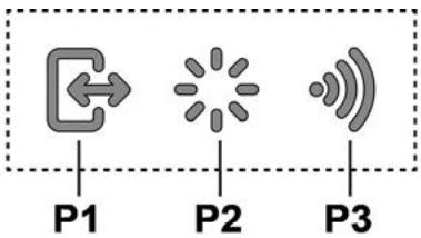
P1. Speed selection button P2. Light ON/OFF button P3. WiFi button
P1. Speed selection button
When the panel is closed, press P1 to turn on the hood and select the speed. The motor and light can be controlled via the control panel.
The cable is 60 cm long. Press and hold the button for 3 seconds to turn on the device. The indicator light will turn on. The device will operate in the selected mode.
Note: If the cable is not connected to the device, the display will show an error. The cable is only for charging, not for data transfer.
P2. Power ON/OFF (On/Off) Button
When the cable is connected, press and hold the P2 button for 3 seconds to turn on the device. The power indicator will light up only when the device is turned on.
When the device is on, the power indicator will remain lit until it is turned off.
Note: The P2 button is used to turn the device on and off, and to switch between ON and OFF modes.
P3. WiFi Button
To configure WiFi settings: If the WiFi function is enabled, press and hold the button for 2 seconds to enter the configuration mode and follow the procedure.
To connect to a network for future use, press the "WiFi Key" button.
To stop WiFi configuration, press the button once and then press and hold it for 2 seconds.
After the WiFi function is disabled, to reset WiFi parameters, press and hold the button for 6 seconds (the indicator will flash) and then follow the reset procedure.
- WiFi on/off: After configuration, the WiFi function can be turned on or off. 1. To turn the WiFi function on or off, press and hold for 2 seconds. This function will enable or disable the WiFi parameters.
WiFi Key button
| WiFi туймeci | Курьлгыньи Косылу Куи |
| Шam ошipurи | WiFi реттелmerен Немес ошipurи |
| Туракты жану | WiFi косуны |
| Шam тeз Жылblытayda | WiFi рочеріпene Косылу эразекti opbyнданы |
| Шam bая Жылblытайды | Elica boлына Косылу эразекti opbyнданы |
| Шam канады, бірак кыісkaша Жылblытайды | Кашытан пэрмен Кабылдануда (Mbісаны, КоЗгалтКышты otanдану Немесшam'dы сэндipy) |
In the display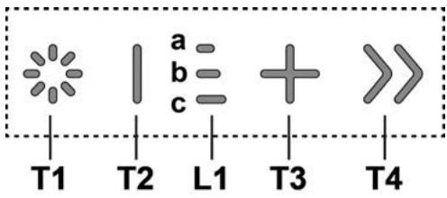
T1. Power ON/OFF (On/Off) Button T2. Charging/Motor Control Button
L1. XbIaDmbk INdNkaTOpbHbH XUd IaMbI Kocybl
T3. MoTOpIbI Kocy/kipic aFbIH XbIJaMdbIbIFbIH apTTbipy Tymeci
T4."BOOST" (Te3eTy)-KapKbIHDbI KblJaMdbIK cyHKUcBbHITyIMeci
T1: WAMHBIN ON/OFF (Kocy/ωipy) Tymeci WAMDbI KOCyFA JHHe Ewipye apHaFraH.
UAMHBHJXapbIK KyuH apTbIpy He KeMity yuH T1 TymeciH 6acbl TypbHb3.
T2: XblnamdbkTBa3aHTy / MOTOPbI Θwipy TYmeci kipic KyaattbI a3aHTy TYmeciH TYTIH TapTKbIu ΘwkeHwe 6acbIbI3.
Tytih TApTkbltBti TkeJe eWipij3.
L1: XbIaMdbIK INdkaTopbIHbIH XUd waMbIKocybl
opTaNbIKXUJIwamapbI6eNceHJI/naiJaNaHbINrA H Kipic aFbIH XbIJaMdbfBHa 6aNaHbICTb JxHaDbI:
1-JbIJaMdbIKAДIOtBlaMaBlaKaHaDbI 2-Жылдамдьк, a+bДиоДышamдарыжанды 3-ЖылдамдьК, a+b+CДиОТышamДарыЖанды
T3: XbIaamdbiktbI aprtbipy Tymeci
Tytih TaptKbIitb icke Kocy yuin 6abih3
Kipic KyattbI apTbIpy yuiH 6acbl3.
T4:"BOOST"(Te3dety)-KapKbIHbI XbIJaMaMbIK cyHKUcBtHbI Tymecci
30 MnHyT yaKbITKa KoBbINFaH "BOOST 1" KapKbIHbI Kipic XbIaDAMbIFbH 6eIceHdipy yuH, T4 TyIeMeiH bAcBbIb3 OCb Y3apTbINFaH yaKbIT Nicipy 6apbcBHaTaYTHIn H KEN MEnIeepH bIbRapaTbH TaMaK e3ipNeY tvPneI yuH naBbIKbTbN CiPy yaKbITbIH B6OyBaHa KeinIIdk 6epyre aPhaIaNfH
After 30 minutes, the first wash cycle will start automatically.
MODE "BOOST 1" (1st speed) will start automatically after 4 minutes, "BOOST 2" will start after 7 minutes.
After 7 minutes, the first wash cycle will start automatically.
After the first wash cycle, to start the second wash, press the button for 7 minutes.
If "BOOST1" and "BOOST2" functions are not selected, press the button:
To start the second wash cycle, press the button.
To start the third wash cycle.
** The indicator lights will turn on.
After the second wash cycle, the machine will stop automatically, and the door will unlock.
When the "BOOST" (speed) functions are selected, the water temperature will be:
("BOOST 1" (1st speed): cold water - "BOOST 2" (2nd speed): hot water)
Technical service
Maintenance
For maintenance, use only a dry cloth.
Do not use abrasive cleaners.
KYPbIFbIHbHEMECE TA3AJAY KYPJAIBH
PANDAJAHSAHbI3!A6pa3nJIbIKKocnacbl6ap
3aTTbI naJaIaN6aHbI3. CnIPTTI
ПАДАЛАБАнь3!
MaCy3rici
AcaaBbHdayaBfMaM6eIweKtepiH yctanKaIaDbI.
Фильтд ai caibH JxbyI 3aTtapMHe KOLmH Hemece TEmH TemNepatypada JxHE YHEMDJI Jxyy UKmNlHderi bIDbc JyBbI MaunHacbIHa Ta3anlan Type Kepek (Hemece Fnblrtd KaHbKltby JxNyeci, erep ciDJI yrInpe60nc4,6beipreH KaxketTIinIKTI KepcetKeH XaFdaJ).
MaJdbI Ta3anay FmNbTpI BiDbic Xyfblw MaunHacbImeH xyraHa eHcizdeHyi MyMKIn. Bipak OhbH, Ta3anay CnataBly MynDe e3repMei.
MaCy3rinepi MeN KeMip cy3rinepiH kipicTipy He aJIbIn Tactay Ke3iHne CopFbIu KaKNaFbIHbIH aJIbHaTbIH 6eJIirHJxMbICCbI3 Kynde eKeHih TEKcepiH3.
Coadan coh andbihfb taKaTawacbH 6ip yaKbTTa ep 6enirinH jofapfb JafbH TapTy apkbInb anbln TaCTaHb3.
TaktaMa maCy3rinepi Kipictipiny uin anFa Kaapan Tepkeipiei.
18-21-cyper
Kemip cy3riw (tek cy3riw-copfbw TypiHde)
Ac nicipren Ke3de xapamcb13 niicti yctan kanaDbI.
XyblaTbIH KEmipJIΦnIbTp.
If the device is not used in accordance with the manufacturer's instructions (if it is not installed in the correct position as indicated in the warning), it may cause injury or damage. The device should be used with the appropriate guards and at a temperature of 65°C, as specified in the operating manual.
The filter and the suction unit should be cleaned after 10 minutes of use at 100°C in the oven.
The pipe should be checked for any damage or material defects before use.
The device should be disconnected from the power supply before cleaning (see above).
Operation
The housing is made of high-quality plastic, resistant to impact.
The plastic parts are resistant to high temperatures, lasting up to 10 times longer than standard parts, and save up to 90% of electrical energy.
The device should be connected to a properly grounded outlet.
At speed 1, LED a lights up; at speed 2, LEDs a and b light up; at speed 3, LEDs a, b, and c light up.
T3: Speed increase button
Press to turn on the hood.
Press to increase suction power.
21-18
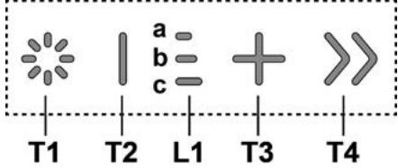
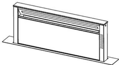
(1) ON/OFF 2. T1
- 4000 Cie yu - «BOOST» aiaaaii iaiaiii j :T4 sall «BOOST 1» aikll baiill ac yu Jauai T4 laai a30 sial ci all (5) yu zaii jia jia jia jia jia jia jia jia jia jia jia jia jia jia jia jia jia jia jia jia jia jia jia jia jia jia jia jia jia jia jia jia jia jia jia jia jia jia jia jia jia jia jia jia jia jia jia jia jia jia jiu 30 ll sio elaiai: aaiy *** leiina
(1) ON/OFF 2. P2
. www.elica.com
EN/IEC 60335-2-31:EN/IEC 60335-1:
EN/IEC 62233
ISO 5167-1 EN/IEC 61591
EN/IEC 60704-1 ISO 5168 ISO 5167-3
ISO 3741 EN/IEC 60704-3 EN/IEC 60704-2-13
IEC 62301 EN 50564
CISPR 14-1:EN55014-1:blz
EN/IEC 61000-3-2 CISPR 14-2 EN 55014-2
ETSI EN 301 489-1 EN/IEC 61000-3-3
ETSI EN 300 328 ETSI EN 301 489-17
IEC 62311:2019


Therefore, a1 = 2, and a(n+1) = 1 / (2 * (a(n) + a(n+1))).
Therefore, the area of triangle AOB equals the area of triangle COD plus the area of triangle BOC minus the area of triangle BOC.


- FRONT
- BACK
- CAUTION
- ELECTRICAL CONNECTION
- INSTALLATION
- GAS COOKTOP
- USE
- EXTRACTION VERSION
- FILTRATION VERSION
- MOUNTING
- PANEL ASSEMBLY
- ELICA CONNECT
- WARNINGS
- OPERATION
- P1. INTAKE PANEL OPENING/CLOSING BUTTON
- P2. LIGHT ON/OFF BUTTON
- P3.WIFI BUTTON
- T2: DECREASE SPEED / MOTOR OFF BUTTON
- FILTER SATURATION INDICATOR LIGHTS
- CLEAN USING ONLY A CLOTH DAMPENED WITH NEUTRAL LIQUID DETERGENT. DO NOT CLEAN WITH TOOLS OR INSTRUMENTS. DO NOT USE ABRASIVE PRODUCTS. DO NOT USE ALCOHOL
- ACTIVATING FILTER SATURATION INDICATOR
- FILTER SATURATION INDICATOR
- RESPECTED
- GAS STOVE TYPE
- WARNING
- EXTRACTION MODE WITH RECIRCULATION
- INSTALLATION OF THE PANEL
- PRECAUTIONS
- INSTRUCTIONS FOR USE
- CONTROL DISPLAY
- P1. BUTTON FOR OPENING/CLOSING THE EXTRACTION FLAP
- P2. LIGHT BUTTON ON/OFF
- P3. WIFI BUTTON
- T2: BUTTON SPEED DECREASE / MOTOR OFF
- L1: LED INDICATOR FOR SPEED ACTIVATION
- T3: BUTTON FOR INCREASING SPEED
- T4: "BOOST" FUNCTION BUTTON - INTENSIVE SPEED
- FILTER INDICATOR FOR REPLACEMENT
- ACTIVATING THE FILTER REPLACEMENT INDICATOR
- OIL FILTER
- CARBON FILTER
- CLEANING
- FILTER FOR THE MACHINE
- FILTER WITH ACTIVE CARBON (FOR SELF-FILTERING VERSION)
- WHEN THE ACTIVE CARBON IS EXHAUSTED
- HOOD DIMENSIONS
- USING THE HOOD IN AIR EXTRACTION MODE
- ATTENTION
- USE OF RECIRCULATION
- AIR
- FLUE INSTALLATION
- REQUIRED INFORMATION
- L1: INDICATOR LIGHTS - SWITCH ON SPEED
- T3: SPEED INCREASE BUTTON
- T4: "BOOST" FUNCTION BUTTON - INCREASED SPEED LEVELS
- FILTER CLOGGING INDICATORS
- RESET OF FILTER CLOGGING INDICATION
- SWITCHING ON THE FILTER CLOGGING INDICATOR
- VERSION WITH RECIRCULATION FILTER
- PANEL INSTALLATION
- ELECTRICAL CONNECTIONS
- CONNECTION
- GAS TYPES
- CLEANING INSTRUCTIONS
- WATER SUPPLY
- NOTE
- CONTROLS
- CONTROL PANEL
- P1. SPEED SELECTION BUTTON
- P2. POWER ON/OFF (ON/OFF) BUTTON
- TECHNICAL SERVICE
- MAINTENANCE
- KYPBIFBIHBHEMECE TA3AJAY KYPJAIBH
- MACY3RICI
- KEMIP CY3RIW (TEK CY3RIW-COPFBW TYPIHDE)
- ON/OFF 2. P
Brand : ELICA
Model : GETUP BLGL/A/90
Category : Kitchen hood