AC310H - Compressor MAKITA - Free user manual and instructions
Find the device manual for free AC310H MAKITA in PDF.
| Brand | MAKITA |
| Model | AC310H |
| Product type | Air compressor |
| Dimensions (L x H x D) | 476 x 375 x 507 mm |
| Weight | 36 kg |
| Power supply | 220-240 V AC, 50 Hz, single-phase |
| Max. input power | 1800 W |
| Tank size | 6.2 L (1.6 gal) |
| Cut-in pressure | 2.3 MPa (23 bar) |
| Cut-out pressure | 2.8 MPa (28 bar) |
| Max. HP outlet pressure | 2.6 MPa (26 bar) |
| Max. RP outlet pressure | 0.9 MPa (9 bar) |
| Sound power level | 90 dB |
| Air flow at 40 PSI (2.8 bar) | 3.7 ft³/min (106 L/min) |
| Air flow at 90 PSI (6.2 bar) | 3.6 ft³/min (101 L/min) |
| Air flow at 300 PSI (21 bar) | 2.7 ft³/min (77 L/min) |
| Lubrication | Self-lubricating (maintenance-free) |
| Motor protection | Thermal circuit breaker with manual reset |
| Main functions | HP and RP pressure regulators, pressure gauges, pressure switch, safety valve, check valve, drain valve |
| Maintenance and cleaning | Daily tank draining, air filter cleaning, safety valve check |
| Safety | Mandatory grounding, wear safety glasses, do not inhale compressed air |
| Spare parts and repairability | Use only genuine Makita parts; have repairs done by an authorized service center |
| General information | Duty cycle 50% max; do not use for inflating small objects |
Frequently Asked Questions - AC310H MAKITA
User questions about AC310H MAKITA
0 question about this device. Answer the ones you know or ask your own.
Ask a new question about this device
Download the instructions for your Compressor in PDF format for free! Find your manual AC310H - MAKITA and take your electronic device back in hand. On this page are published all the documents necessary for the use of your device. AC310H by MAKITA.
USER MANUAL AC310H MAKITA
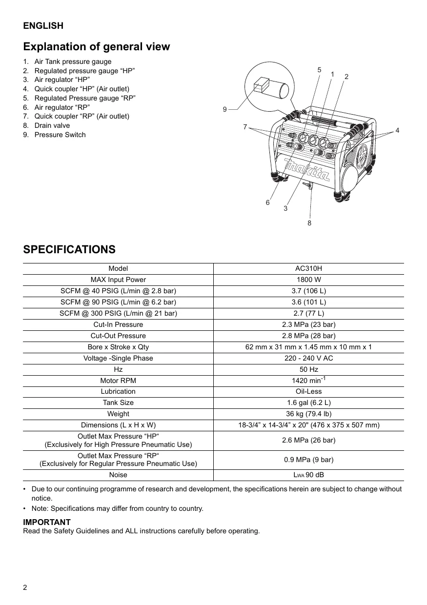
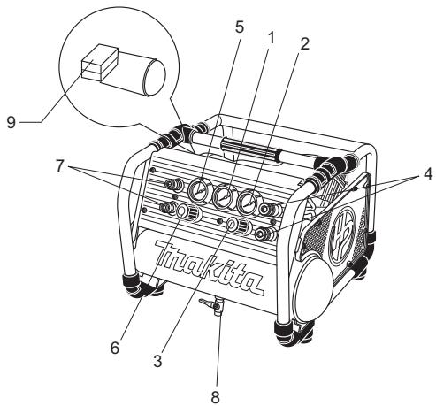
Explanation of general view
- Air Tank pressure gauge
- Regulated pressure gauge "HP"
- Air regulator "HP"
- Quick coupler "HP" (Air outlet)
- Regulated Pressure gauge "RP"
- Air regulator "RP"
- Quick coupler "RP" (Air outlet)
- Drain valve
- Pressure Switch
SPECIFICATIONS
| Model | AC310H |
| MAX Input Power | 1800 W |
| SCFM @ 40 PSIG (L/min @ 2.8 bar) | 3.7 (106 L) |
| SCFM @ 90 PSIG (L/min @ 6.2 bar) | 3.6 (101 L) |
| SCFM @ 300 PSIG (L/min @ 21 bar) | 2.7 (77 L) |
| Cut-In Pressure | 2.3 MPa (23 bar) |
| Cut-Out Pressure | 2.8 MPa (28 bar) |
| Bore x Stroke x Qty | 62 mm x 31 mm x 1.45 mm x 10 mm x 1 |
| Voltage -Single Phase | 220 - 240 V AC |
| Hz | 50 Hz |
| Motor RPM | 1420 min-1 |
| Lubrication | Oil-Less |
| Tank Size | 1.6 gal (6.2 L) |
| Weight | 36 kg (79.4 lb) |
| Dimensions (L x H x W) | 18-3/4" x 14-3/4" x 20" (476 x 375 x 507 mm) |
| Outlet Max Pressure "HP" (Exclusively for High Pressure Pneumatic Use) | 2.6 MPa (26 bar) |
| Outlet Max Pressure "RP" (Exclusively for Regular Pressure Pneumatic Use) | 0.9 MPa (9 bar) |
| Noise | LWA 90 dB |
- Due to our continuing programme of research and development, the specifications herein are subject to change without notice.
Note: Specifications may differ from country to country.
IMPORTANT
Read the Safety Guidelines and ALL instructions carefully before operating.
Symbols
The following show the symbols used for the equipment.
Be sure that you understand their meaning before use.

Read instruction manual.

Risk of electric shock. Caution: before doing any work on the compressor it must be disconnected form the power supply.

Risk of high temperatures. Caution: the compressor contains some parts which might reach high temperatures.

Risk of accidental start-up. Attention, the compressor could start automatically in case of a black-out and subsequent reset.

Wear safety glasses.

Only for EU countries Do not dispose of electric equipment together with household waste material! In observance of European Directive 2002/96/EC on waste electrical and electronic equipment and its implementation in accordance with national law, electric equipment that have reached the end of their life must be collected separately and returned to an environmentally compatible recycling facility.
IMPORTANT SAFETY INSTRUCTIONS
WARNING
READ AND UNDERSTAND ALL INSTRUCTIONS
Failure to follow all instructions listed below may result in electric shock, fire, and/or serious injury.
SAVE THESE INSTRUCTIONS.
WORK AREA
-
Keep your work area clean and well lit. Cluttered and dark areas invite accidents.
-
Do not operate power tools in explosive atmospheres, such as in the presence of flammable liquids, gases, or dust. Power tools create sparks which may ignite the dust or fumes.
- Keep bystanders, children, and visitors away while operating a power tool. Distractions can cause you to lose control. Protect others in the work area from debris such as chips and sparks. Provide barriers or shields as needed. Children should never be allowed in the work area.
- The adequate room tempure is +5^ to +30^ . (0^ to +40^ at Maximum)
WARNING
IMPROPER OPERATION OR MAINTENANCE OF THIS PRODUCT COULD RESULT IN SERIOUS INJURY AND PROPERTY DAMAGE.
READ AND UNDERSTAND ALL WARNINGS AND OPERATING INSTRUCTIONS BEFORE USING THIS EQUIPMENT.
WARNING
Risk of Unsafe Operation
WHAT CAN HAPPEN
Unsafe operation of your air compressor could lead to serious injury to you or others.
HOW TO PREVENT IT
- Review and understand all instructions and warnings in this manual.
- Become familiar with the operation and controls of the air compressor.
- Keep operating area clear of bystanders, pets and obstacles
- Keep children away from the air compressor at all times.
- Do not operate the product when fatigued or under the influence of alcohol or drugs. Stay alert at all times.
- Never defeat the safety features of this product.
- Do not operate machine with missing, broken, or unauthorised parts.
WARNING
Risk of Air Tank Bursting
WHAT CAN HAPPEN
The following conditions could lead to a weakening of the tank, and RESULT IN A VIOLENT TANK EXPLOSION RESULTING IN SERIOUS INJURY TO YOU OR OTHERS:
- Failure to properly drain condensed water from the tank, causing rust and thinning of the tank wall.
- Modifications or attempted repairs to the tank.
- Unauthorised modifications to the pressure switch, safety valve, or any other components, which control tank pressure.
HOW TO PREVENT IT
- Drain air tank daily or after each use. If air tank develops a leak, replace it immediately with a new tank or replace the entire compressor.

- Do not drill into, weld or otherwise modify air tank or it will weaken. The tank can rupture or explode. Replace with a new air tank.
- Follow the equipment manufacturers recommendation and never exceed the maximum allowable pressure rating of attachments. Never use the compressor to inflate small low-pressure objects such as children's toys, footballs, basketballs, etc.
WARNING

Risk of Attachments and Accessories Bursting
WHAT CAN HAPPEN
Exceeding the pressure rating of air tools, spray guns, air operated accessories, tyres AND other inflatable can cause them to explode or fly apart, and could result in serious injury to you and others.
WARNING

Risk of Electric Shock
WHAT CAN HAPPEN
- Your air compressor is powered by electricity. Like any other electrically powered device, if it is not used properly, it may cause electrical shock.
- Electrical grounding: failure to provide adequate grounding to this product could increase the risk of electric shock.
HOW TO PREVENT IT
- Any electrical wiring or repairs required to this product should be performed by qualified service personnel or a qualified electrician, in accordance with national and local electrical codes.
- Make certain that the electrical circuit to which the compressor is connected provides proper electrical grounding, correct voltage, and adequate fuse protection.
- Never operate the compressor outdoors when it is raining, or in a wet environment.
- Never operate the compressor with guards or covers which are damaged or removed.
WARNING
Risk of Explosion or Fire
WHAT CAN HAPPEN
It is normal for electrical contacts within the motor and pressure switch to spark, whenever the compressor starts or stops. Never operate the compressor in an atmosphere where flammable vapours are present. Doing so can result in serious injury to you or others.
HOW TO PREVENT IT
- Always operate the compressor in a well-ventilated area, free of gasoline or solvent vapours.
- If spraying flammable materials, locate compressor at least 6.1m away from spray area.
- Store flammable materials in a secure location away from compressor.
WARNING

Risk to Breathing
WHAT CAN HAPPEN
- The compressed air from your compressor is not safe for breathing.
The air stream may contain carbon monoxide or other vapours, or particles from the tank or other components.
- Sprayed materials such as paint, paint solvents, paint remover, insecticides, weed killers, etc., contain harmful vapors and poisons.
- Breathing compressor or sprayed materials vapor can result in serious injury.
HOW TO PREVENT IT
- Never inhale air from the compressor, either directly or from a breathing device connected to the compressor. Work in an area equipped with good cross ventilation.
- Read and follow the safety instructions provided on the label or safety data sheet for the material you are spraying.
Use an approved respirator designed for use with your specific application.
WARNING
Risk from Noise

Risk from Compressed Air

WHAT CAN HAPPEN
The compressed air stream can cause soft tissue damage, and can propel dirt, chips, loose particles and small objects at high speed, resulting in property damage or personal injury.
HOW TO PREVENT IT
Always wear approved safety glasses with side shields when using or maintaining the compressor.
- Never point any nozzle or sprayer toward any part of the body or at other people or animals.
- Always turn the compressor off and bleed pressure from the air line before attempting maintenance, attaching tools or accessories.
WARNING

Risk from Moving Parts
WHAT CAN HAPPEN
The compressor cycles automatically when the pressure switch is in the on/auto position. If you attempt repair or maintenance while the compressor is operating or plugged in, you can expose yourself to moving parts.
These moving parts can cause serious injury.
HOW TO PREVENT IT
Always unplug the compressor and release air pressure from the tank and any attachments before attempting any maintenance or repair.
- Never operate the compressor with guards or covers which are damaged or removed.
- Keep your hair, clothing, and gloves away from moving parts. Loose clothes, jewellery, or long hair can be caught in moving parts.
Air vents may cover moving parts and should be avoided as well.
WARNING

Risk of Burn
WARNING
Do not operate the portable compressor with the doors or enclosures open!

WARNING
Do not open the cock before the air hose is attached!

WHAT CAN HAPPEN
Contact with hot parts such as the compressor head or outlet tubes could result in a serious skin burn.
HOW TO PREVENT IT
- Never touch hot components during or immediately after operation of the compressor. Do not reach around protective shrouds or attempt maintenance until unit has been allowed to cool.
- The handling and lifting: hold the handle only when move or transport the compressor.
- To avoid injuring, do not touch the cylinder, cylinder head or exhaust hose and other over-heated parts when the compressor is in use or shuts off within one hour.
WARNING
Transport
a The maximum bevel during traction is at least 30^
b Do not apply vehicles for traction.
c Do not place compressor under inflammable, explosive or erosive service.
GLOSSARY
CFM: Cubic feet per minute.
SCFM: Standard cubic feet per minute; a unit of measure of air delivery.
PSIG: Pounds per square inch gauge; a unit of measure of pressure.
CUT-IN PRESSURE: While the motor is off, air tank pressure drops as you continue to use your accessory or air tool. When the tank pressure drops to a certain level the motor will restart automatically. This is called "cut-in pressure".
CUT-OUT PRESSURE: When you turn on your air compressor, it begins to run, air pressure in the air tank begins to build. It builds to a certain pressure before the motor automatically shuts off - protecting your air tank from pressure higher than its design rating. The pressure at which the motor shuts off is called "cut-out pressure".
DUTY CYCLE
All Makita manufactured air compressors are recommended to be operated at no more than a 50% duty cycle. This means an air compressor that pumps air more than 50% of one hour is considered misuse because the air compressor is undersized for the required air demand.
GENERAL INFORMATION
This air compressor is equipped with an Oil-Less pump designed for durability and no maintenance.
The compressor can be used for properly rated pneumatic nailers and staplers. An air pressure regulator is supplied for these applications.
WARNING:
Never use compressor for applications other than to operate a properly rated nailer or stapler. Use of the compressor for other applications could result in property damage and personal injury.
Separate air filter regulators combine the functions of air regulation and/or moisture and dirt removal should be used where applicable.
ON-RECEIPT INSPECTION
DAMAGE: Each air compressor outfit is carefully tested and checked before shipment. With improper handling, damage may result in transit and cause problems with compressor operation.
Immediately upon arrival, check equipment for both concealed and visible damages to avoid expenses being incurred to correct such problems. This should be done regardless of any visible signs of damage to the shipping container. If this product was shipped directly to you, report any damages to the carrier and arrange for inspection of goods immediately.
STORAGE
Before you store the air compressor, make sure you do the following:
-
Review the "Maintenance" and "Operating Procedures" sections and perform maintenance as necessary. Be sure to drain water from the air tank.
-
Protect the electrical cord and air hose from damage (such as being stepped on or run over).
Store the air compressor in a clean and dry location.
DESCRIPTION OF OPERATION
DRAIN VALVE: The drain valve is located at the bottom of the air tank and is used to drain condensation from the tank at the end of each use or daily.
THERMAL CIRCUIT BREAKER:
The electric motor has a manual reset thermal circuit breaker. If the motor overheats for any reason, the circuit breaker will shut off the motor. Turn pressure switch to the "off" position and wait for unit to cool before pushing the reset button and restarting the compressor.
MOTOR THERMAL OVERLOAD PROTECTOR:
When the current rating of the motor is exceeded the thermo-protector will open and shut off the motor automatically.
The motor must be allowed to cool down before restarting. The compressor will automatically restart after the motor has cooled down.
ON/AUTO-OFF SWITCH:
Turn this switch to "on" to provide automatic power to the pressure switch and to "off" to remove power when finished using the compressor or when compressor will be left unattended.
AIR INTAKE FILTER:
This filter is designed to clean air coming into the compressor pump. This filter must always be clean and free from obstructions. See "Maintenance".
AIR COMPRESSOR PUMP:
To compress air, the piston moves up and down in the cylinder. On the down stroke, air is drawn in through the air intake valve. The exhaust valve remains closed. On the upstroke of the piston, air is compressed. The intake valve closes and compressed air is forced out through the exhaust valve, through the outlet tube, through the check valve and into the air tank. Useable air is not available until the compressor has raised the air tank pressure above that required at the air outlet.
CHECK VALVE:
When the air compressor is operating, the check valve is "open", allowing compressed air to enter the air tank. When the air compressor reaches "cut-out" pressure, the check valve "closes", allowing air pressure to remain inside the air tank.
PRESSURE SWITCH UNLOADING VALVE:
The pressure switch unloading valve located on the side of the pressure switch, is designed to automatically release compressed air from the compressor head and the outlet tube when the air compressor reaches "cut-out" pressure.
PRESSURE SWITCH:
The pressure switch automatically starts the motor when the air tank pressure drops to the factory set "cut-in" pressure. It stops the motor when the air tank pressure reaches the factory set "cut-out" pressure.
SAFETY VALVE:
If the pressure switch does not shut off the air compressor at its "cut-out" pressure setting, the safety valve will protect against high pressure by "popping out" at its factory set pressure which is slightly higher than the pressure switch "cut-out" setting.
OUTLET PRESSUREGAUGE:
The outlet pressure gauge indicates the air pressure available at the outlet side of the regulator. This pressure is controlled by the regulator and is always less or equal to the tank pressure. See "Operating Procedures".
TANK PRESSURE GAUGE:
The tank pressure gauge indicates the air pressure in the tank.
REGULATOR:
The air pressure coming from the air tank is controlled by the regulator knob. Turn the knob clockwise to increase pressure and counter-clockwise to decrease pressure. To avoid minor re-adjustment after making a change in pressure setting, always approach the desired pressure from a lower pressure. When reducing from a higher to a lower setting, first reduce the pressure less than the desired pressure. Depending on the air requirements of each particular accessory, the outlet regulated air pressure may have to be adjusted while you are operating the accessory.
COMPRESSED AIR OUTLET; "HP" marking For High Pressure Pneumatic Tool Exclusive Use Outlet Max Pressure; 2.6 MPa (26 bar)
COMPRESSED AIR OUTLET, "RP" marking For Regular Pressure Pneumatic Tool Use Outlet Max Pressure; 0.9 MPa (9 bar)
INSTALLATION AND BREAK-IN PROCEDURES
LOCATION OF THE AIR COMPRESSOR
Locate the air compressor in a clean, dry and well-ventilated area. The air filter must be kept clear of obstructions, which could reduce air delivery of the air compressor. The air compressor should be located at least 0.3m away from the wall or other obstructions that would interfere with the flow of air. The air compressor head and shroud are designed to allow for proper cooling. If humidity is high, an air filter can be installed on the air outlet adapter to remove excessive moisture. Follow the instructions packaged with the air filter for proper installation.
Place the air compressor on a level surface so that it rests securely on the rubber feet.
LUBRICATION
This air compressor is equipped with an Oil-Less pump designed for durability and no maintenance.
Power supply
Operate the compressor at voltages specified on the nameplate, the allowable tolerance range must remain within ± 5% . If using the compressor at a higher voltage than the rated voltage, it will result in abnormally fast motor speed and may damage the unit and burn out the motor.
Extension Cords
To avoid voltage drop, power loss, and overheating of the motor, use extra air hose instead of an extension cord. Low voltage can cause damage to the motor.
If an extension cord must be used:
- Make sure the extension cord is in good condition.
Please see the chart below for the MINIMUM extension cord gauge requirements:
| Amp Rating Range (220 - 240 V) | Total Length of Cord in Meter | |||||
| 10 m25 ft. | 15 m50 ft. | 20 m75 ft. | 30 m100 ft. | 50 m150 ft. | 60 m200 ft. | |
| 0 - 5 A | 1.5 mm² | 1.5 mm² | 1.5 mm² | 2.5 mm² | 4 mm² | 4 mm² |
| 5.1 - 8 A | 1.5 mm² | 1.5 mm² | 2.5 mm² | 4 mm² | 4 mm² | 4 mm² |
| 8 - 12 A | 2.5 mm² | 2.5 mm² | 4 mm² | Not Recommended | ||
Piping
Plastic or PVC pipe is not designed for use with compressed air. Regardless of its indicated pressure rating, plastic pipe can burst from air pressure. Use only metal pipe for air distribution lines. If a pipe line is necessary, use pipe that is the same size, or larger than, the air tank outlet. Piping that is too small will restrict the flow of air. If piping is over 100 feet long, use the next larger size. Bury underground lines below the frost line and avoid pockets where condensation can gather and freeze. Apply pressure before underground lines are covered to make sure all pipe joints are free of leaks.
DANGER:
Improper grounding can result in electrical shock. Do not modify the plug that has been provided. If it does not fit the available outlet, the correct outlet should be installed by a qualified electrician.
OPERATING PROCEDURES
Daily Start-up Checklist
CONNECTING HOSES
WARNING:
Risk of unsafe operation. Firmly grasp hose in hand when installing or disconnecting to prevent hose whip.
Losing control of the hose may result in personal injury and property damage.
- Before attaching air hose or accessories, make sure the pressure switch lever is set to "OFF" and the air regulator or shut-off valve is closed. Ensure compressor is disconnected from the mains supply.
- Attach hose and accessories. Too much air pressure causes a hazardous risk of bursting. Check the manufacturer's maximum pressure rating for air tools and accessories. The regulator outlet pressure must never exceed the maximum pressure rating.
- Turn the pressure switch lever to "ON/AUTO" and allow tank pressure to build. Motor will stop when tank pressure reaches "cut-out" pressure.
- Open the regulator by turning it clockwise. Adjust the regulator to the correct pressure setting. Your compressor is ready for use.
- Always operate the air compressor in well-ventilated areas; free of gasoline or other solvent vapors. Do not operate the compressor near the spray area.
When you are finished:
DISCONNECTING HOSES
WARNING:
Risk of unsafe operation. Firmly grasp hose in hand when installing or disconnecting to prevent hose whip.
Losing control of the hose may result in personal injury and property damage.
- Set the pressure switch lever to "OFF". Ensure compressor is disconnected from the mains supply.
- Using the air tool or accessory, bleed the tank pressure down to zero.
- Remove the air tool or accessory.
- Drain water from air tank by opening drain cock valve on bottom of tank. WATER WILL CONDENSE IN THE AIR TANK. IF NOT DRAINED, WATER WILL CORRODE AND WEAKEN THE AIR TANK CAUSING A RISK OF AIR TANK RuptURE.
Note:
If drain valve is plugged, release all air pressure. The valve can then be removed, cleaned, then reinstalled.
- After the water has been drained, close the drain valve. The air compressor can now be stored.
WARNING:
Drain Air Tank Properly. Improper draining of the air tank can result in corrosion and possible bursting of the tank. Tank bursting could lead to personal injury and property damage.
MAINTENANCE
WARNING:
Never use the air compressor which is operating abnormally.
If the air compressor appears to be operating unusually, making strange noises or vibration, stop using it immediately and arrange for repairs by a Makita authorized service center.
WARNING:
Use only genuine Makita replacement parts. Replacement parts not manufactured by Makita may void your warranty and can lead to malfunction and result in injuries. Genuine Makita parts are available from an authorized dealer.
WARNING:
UNIT CYCLES AUTOMATICALLY WHEN POWER IS ON. WHEN DOING MAINTENANCE, YOU MAY BE EXPOSED TO VOLTAGE SOURCES, COMPRESSED AIR OR MOVING PARTS. PERSONAL INJURIES CAN OCCUR. BEFORE PERFORMING ANY MAINTENANCE OR REPAIR, UNPLUG THE COMPRESSOR AND BLEED OFF ALL AIR PRESSURE.
To ensure efficient operation and longer life of the air compressor unit, a routine maintenance schedule should be prepared and followed. The following routine maintenance schedule is geared to a unit in a normal working environment operating on a daily basis. If necessary, the schedule should be modified to suit the
conditions under which your compressor is used. The modifications will depend upon the hours of operation and the working environment. Compressor units in an extremely dirty and/or hostile environment will require a greater frequency of all maintenance checks.
ROUTINE MAINTENANCE SCHEDULE
- Drain water from the air tank, any moisture separators or air filter regulators.
- Check for any unusual noise and/or vibration.
- Manually check all safety valves to make sure they are operating properly.
WARNING: Risk of bursting.
Check Safety Valve. If safety valve does not operate properly over pressurization of the air tank may result in rupture or explosion causing personal injury and property damage.
- Inspect air filter, replace if necessary.
- Inspect air lines and fittings for leaks; correct as necessary.
Each year of operation or if a problem is suspected:
- Check condition of air compressor pump intake and exhaust valves.
-
Check condition of check valve. Replace if damaged or worn out.
-
Keep all screws, bolts, and covers properly tightened.
Check their conditions periodically.
WARNING:
Keep All Screws, Bolts and Covers Properly Tightened. If screws, plates or covers become loose personal injury or property damage may occur.
1) TROUBLE SHOOTING
| PROBLEM | CAUSE | CORRECTION |
| Will not start | Fuse blown or circuit breaker tripped; Loose electrical connections; Extension cord not correct; Overheated motor | Check for cause and replace or reset; Check wiring connections Max.15m/50ft., min. 14ga; Use reset button/wait for automatic reset |
| Low pressure | Air leak in safety valve Restricted air filter Defective check valve | Check valve manually: pull up ward on rings. If condition persists, replace valve; Clean or replace air filter; Replace check valve. |
| Safety valve releasing | Defective pressure switch or improper adjustment | Check for proper adjustment and if problem persists, replace pressure switch |
2) WARNING!
Wrong way to transport and lift will lead machine damaged.
Daily maintenance
- Before each use:
A Be sure all nuts and bolts are tight.
B Check for unusual noise or vibration.
- After each use:
Exhaust all the air in the air storage tank. Open the drain cock at the bottom of the air storage tank to drain condensation from tank.
- Weekly maintenance:
A Check performance of safety valve.
B Check the air switch the designed rated pressure is 2.8 Mpa.
C Clean the air filter.
- Monthly maintenance:
A Inspect air system for leaks by applying soapy water to all joints. Tighten those joints if leakage is observed.
B Check that all nuts and bolts stay tight.
C Replace the air filter with a new one.
D Clean surface of air compressor.
- Quarterly maintenance:
A Check the cylinder and piston see to if wore.
FRANÇAIS
Descriptif
BESCHRIJVING VAN DE WERKING
DIFERENTIAL TÉRMICO:
LUFTKOMPRESSORPUMPE:
TRYKLUFTSUDGANG; "HP"-markering
TRYKLUFTSUDGANG; "RP"-markering
- Hver gang after drug:
Risk for explosion erer brand
DETTA KAN HÄNDA
PLAN FOR RUTINEMESSIG VEDLIKEHOLD
TI MINOPEI NA ZYMBEI
OuovhkeTouavapoeovTtapakatwmuTopeiv a oynouov eEaeovnTgEaevnc, kai NA
IPOKAENEOYN EKPHEHTHEAEMENHME AINTOTEEAEMA TO SOBAPO TPAYMATI2MO 2A2T H TON TPAYMATI2MO AANQN.
H Tnapaleiun nC Oomega nC atoopayvionstou oumuieevou vepou atoT noeaeuyn, Tpokaei oKoupia kai AETTuvon TwTOxWmuTuw nS eaeuync.
- Metatpontes n antoiteipes etiokeunc otn eoevn.
AubaipeTeC metatpotoc 0to diakotttn niean, otn
baiaiaoaaaeiac, n e oioaodntote aaaa
eapntmaataoiaeayxouv nvi tnean ts
eaeaeyns.
IΩΣ NA TON ANOΦYΓΕT
AIOOtpayyicTe Tn a n aepa kaθημeipiva n eTa ano kaeXpnon. Av tnpEi giappOn anTn a n aepa, avtikataoTnote Tn auεωc v e vaea a n avtikataoTnote dto ooumTneT.
Mn tputtnoete, ouykoalaote n kavete aaec metatopotnc otnt deqaeuve npaia th a eaoevoie H doeaev mtopei va pae npn n va ekpayei. Avtkataotnote me ia vea deqaeuve aepc.
Akoouhote TIG ouotaceic TWV kataokeuaotuv Tou EOTIAIOU KAI TOTe VA uNv UTPepbaivete TN eviotn ETIPETITN OVOaOTIKT NIEON TUV EApTNATW.VIOTe va un xpoioiOIOIE To oUPTIEOTN VIA VA qouokwETe Mkpa avtikeva xaunlnc TIIeONS OTWC TAIIDKA TAIxVIDia, mTALcTIOOOqaipou, mTAeC mTAAKET, KAATT.
NPOEIADONOIHSH
KivduoG IaappnIgN PpoapntmuTowkai EApntmuTow

TI MINOPEI NA ZYMBEI
Av utepbeta tyn ovoaotik nieon twv epyaleiw aepoc, TW TNIOTAOIW YEAQAAUW TUV EApntuATW TIOAIEOUPOuv ME aepa, Twv AaoTixuv KAI aaawu AVtkeiEvw vTOPOAKovuAV, uau TIOpei va ekpayouv n va diauaoovtov aepa me atoteEeajua to oobapo Taupatiao oac kai TOpaunatioo aww.
NPOEIADONOIHSH

TI MINOPEI NA ZYMBEI
Eivai quioioyikn n ooioupyia otivnohp aot av utapxouv
naektikec eiaapc me to kivntnpa ka to diaokotttn
tiieo, otoe avaei n o bne o ouitieotns. Note u
aetouyeite to ouuieotn ae piaalov otou utapxouv
avaqeloi atuoi. Av ao toue biopoie a TpokanB
ooapoctpauatiaoic o eack aee alouc.
IΩΣ NA TON ANOΦYΓΕT
Na leioupyeite Tavta to oumtieotn oe ia kai aepioevn Tepioxh, xwiC atoucs Bevivnc n diautikou.
Av ekadoet Eupkta uik, TOToTeTto OUMIEOTe aTtOaTouaxiTo6,1uTPOaTTOv TEPIOXnEkaoou.
ATo0hKeUoTe Ta EucKtuaIka Oe aOpaln TOnTOEoiia paia atoTov ouiTTIEOTn.
IPOEIAOIOIHsH

Kivuoc otv Avantvo
TI MNOPEI NA SYMBEI
- éiασραλες va αναντέετε tov συμπιεσμενο αέρα πότον συμπιεσή σας.
Toeepua aepocmuopei va tpiepexei diaoeidio tou avBpaka n alouc atmuoc, n oomegaia atto n 8eaevni n aa ooutikai.
Ta ulika yekacogou otncn toyia, ta diautikaktoyic, to dialutiko xpawatos, ta evojoktova, ta zcavioktova, kT, Pteipexovb aalepeouc atouc kai dnantpiia.
H EiTIVoN aIou aIIO Tov aUIMIEOTn anTO uIKA yEkaOu oITopei va TTPOKaIeoi OoBapo TpaUaTioMu.
IΩSNATONANOΦYΓETE
Ioté va univioiVéTE aepa ato tvou oumtiEOT, eite atuueEiae iTe ato avatnuotikn ouokeun Tou uovdctai tevouuTIEOT. Na epyaceote OE tpioxn tou eivai eOtoieevn keao aepioo antokpne akpn.
Aiaaote kai tnpieote Tc oyniecg aopaaieacTou TAPEXOVTa OTNv ETKETa n OTO quLAA TOIpoopoiw aopaaieac yia To uAIKO TOU yekaceTc XpnoiIOiTNEva EYKEKPIeVO avATNVUOTnpa Tnou Exei Oxediatoi YIA xPOnn e Tn dIKn OAuyKKePiEvn Epapuoyn.
Kivduvoa oEeAep
TI MINOPEI NA ZYMBEI
Topeuotaoumuieouaepa mtoeiva Tpokaaleo0patoaakotokai va oetai TPOC taepocakaopae,pokavbia,eaueepa oomegaia kai kipoaovtkeleva, e atotetaeaunTpopa idioktniaqntovatooikotpaumiao.
TI MINOPEI NA ZYMBEI
O ouuTieotns oloknpwvei tvkVnoI tou autouata otav O diaokontn Tieoans Bioketai otn Eoan "on/auto". Av etIXeipnoeTe va kTeLaote Ete Etokeun n ouvtnpon e w O ouuTieotnc letoupye i eivatnv TpiCa, mTopei va kTeTheiE 0 Kivduvo ato ta kiovoueva Eaaptnaata. Auta ta Kiovoueva Eaaptnata mTopei va TpokaAeoov Oooapop Taaupatiaqo.
IΩZNA TON ANOΦYFETE
Na ByaCETe TAVTA To OUMTIEOTn AtTo TIV TPIcA KAI VA aTTEAEUBEpWETe TIV TIEON TOu aEPA tTO N DEgauEn KAI ATO OTIOIAODTNE AALAA EApTmATA TTPOTu EITIXEPOEte OTIOIAODNTe UVTNTHNtN n ETIOKEUN.
IotE mJ aeitoupyeTe TO ouMTIEOTn ME TPOoTATEUTiKa n KaUmuata Tnou Eoxuov Oaapei n aapieOeI.
Kpatate ta paalia, ta pouxa kai ta yavria oac jaakpi aTIO KIVOUVEA MEPN. YIAPXei KIVOVOC va eITAAKOUV TA qapdiouxa, ta KOOHNATA n ta jakpia paalia OTA KIVOUVEA MEPN.
Oi aepayuyoi mtopei va kauniouva kivoueva npkai ta pertei kai auto va atopoeuyetai.
NPOEIADONOIH
Kivduos ykauatoS
NPOEIADONOIHSH
Mn xeiipieoTe to oopnto kouptpeoepe TIC
tueps n touc tepioppaKTOCS Xwoucs
aovikTOUs!


IPOEIADONIOIHSH
Mny avoiyet n otpokiyya npotou ouvde8ei o eukamntos owlhvac aepa!
TI MINOPEI NA ZYMBEI
H eTAPn ME 0ePpA pnp OTTN KepaI TOU OumTIeOTn oI OwLnVc EKPOIs mTpei va TpokalEouv OoBap a Eykauapa oTo Depua.
IΩΣ NA TON ANOΦYΓΕT
Na unyayicTe note 0epua eapntnata kata n diakpeia n aoeuc mTa Tn aeiouya tou oumtieatm. Mny naioiace yupw atro ta TpootateutikarepiBnmuata kai uny etixieipeite uvtnpon Ewovovuva Kpuowoe n ovoa
O xεπiαος καινυμωση: Kpatáte to xερούλι μόνο kata tyn μετακίνηση n tyn μεταφορά tou συμπιεόπ.
Tia TnV aToopuyn Tou Tpaumaiou mnu ayyicTe Tov Kauivopou, Tnv KEpaan Tou Kauivopou n To oAwnvac nC Esatmuanc kai Ta aa Tnou zetata eapntmuata otav xpmaotoeiTao uptmteoN h exi Obaeaiiyotepo ano ia wpa vwpitepa.
IPOEIADONIOIHSH
Metaopα
a H kata tnv eAeiv aoulambdaioTov 30^
β Mny xpnoiopoioirooTe oxnupa yia eAeN.
MynxnoiouoioeToVouuTneOeepyaoiesTou evexouvToKivduvoavapalegsekpnnsnbiipwons.
ΓΛΩΣΑPIO
CFM: K iKa Tóδia To λεΤΟ.
SCFM: KavovikakuBikáTóbia to λεπτό, μονáða μετρησις tnc παρoxns tou αέρα.
BRIDJUMS: Coursites risks.
Pärbaudiet drostbas varstu. Ja drostbas varsts nedarbojas pareizi, galsa tvertnes parspiediens var radit uzliesmosanu vai eksploziju, izraisot personiskus levainojumus un ipasuma bojajumus.
- Pärbaudiet gaisa filtru, ja nepiecesams to nomainiet.
-
Pärbaudiet, vai gaisa padeves flijjas un armatură nav nopilūdes; salabojiet, ja nepiecešams. Reizi katra ekspluatacijas gadă vai, ja rodas aizdomas par problemam:
-
Pärbaudiet gaisa kompresora sukna ieplüdes un izplüdes värstu stavokli.
-
Parbaudiet kontroles värsta stavokli. Aizvietojiet, ja tas ir bojats vai nodilis.
-
Saglabajiet visas skruves, aizbtdnus un vakus stingri pieskruvetus.Periodiski parbaudiet to stavokli.
BRIDINAJUMS:
Saglabajiet visas skruves, aizbidenus un vakus stingri pieskruvetus. Ja skruves, plaaksnes val aizbndni atskruvejas, tas var izraisit personiskus iveainojumus um ipasuma bojajumus.
1) TRAUÇEJUMU NOVERŠANA
SURUÖHU VÄLJALASE; tāhistus "HP"
1) RIESENIE PROBLEMOV
TYTO POKNY SI USCHOVEJTE.
PRACOVISTÉ
Puzuk Bn6yxy NoBITpHoro 6aKy
MOXJIINBI HACJIINKIN
HaCTynHmI yMOBIMoKytb np3BeCTn Do nocna6nHnHa 6aKy Ta cnpuHHnITN IOTYHKHNI BNUX BAKY,IO MOKE 3ABDATN CEPHO3HNXPABM BAM TA OTOUYOUHM:
He3a6e3neueHH Heo6xIdHoro 3nMaahHH KOHeHcObaHOI BOni 3 baky, IIO cnpuHnRe ipkabHn Ta nTOHuaHH cTInKb Kaky.
BHeceHn3mIndoKoHcTpkyi6akyTa cnpobn noor nolarodntn.
HeniH3ObAHi 3MHN Do nepeMnKaa TNCy, 3anobixhoro KnaIaNHy uBdyb-kynx iHux KOMNoHEHTIB, IIO KOHTpOJIIOuTb TNCy baky.
YK UbOMY 3ANOBITN
3IINBaIe KOHDeHCoBAHy BOdy 3 NOBITpRHOro 6aKy 10dEHO H aOb nCIE KOKHO RBO NKOPCTAHnRA. JKIOU y 6aKy 3'ABNtBc npOTiKAHN, HERAO 3aMIHTb IORo HA HOBNI 6ak, aO bAMHITb BEc KbOMnPecOp.
He npocBepdIIOte 6ak, He npoBoDbTe Ha HbOMy 3BaPbOaJIbHIpo6OTn, He BHOcTe 3MiH Do Iro KOHCTpyKuII 6dyb-IAkIM IHsIM MInHOM, IHAKUe IroM MiHCt b 6yde NoclaBneHO. BaK MoKE po3JaMaTcNcA 60 BV6xHyTN. 3AmHiTb Ioro Ha HOBNI NOBITpHNI 6ak.
- DToPmMyTeCe iHCTpykui BIVo6bNka 6bnaHaHnra Ta HIKOIN He nepeBnUyIe MaKcMmaJIbHO DoNyCTMI NOKa3HKn TnCKy IINKIOueHOrO 6bnaHaHnra. HIKOIN He BnKOpNCtOBuYIe KOMnPecOp DnRA NaYBaHnra HeBeNikx NpeDMeTIB 3 Hn3bKM TnCKOM, TAKNX Jk DInrAci IrpAaKN, FyTObJIbTI a BacketoBbHI M'qHi Ta IH.
YBATA

Pn3nk Bn6bxy niikJIOueHOro Ta donomixhoro 0bnadhaHH
MOXJIINBI HACNIIDKIN
IpeBnuEHHN oKa3HKnIB TCKy nobiTpyHORO
0bnadHaHH, PO3nHIOBauB, DOnOMIXHOro 0bnaHaNHH
ha NobiTPRHOmy npivBOdi, sinTHA iINxu HADyBHX
npedmetiMOe npin3BeCTn doixhBo rBOvxy a6o
pO3pNV, 1o MoKe 3aBdTa n cepio3Hnx TpaBM Bam Ta
OTOUYOHIM.
YBAGA

Pn3nk ydapy ctpymom
MOXJIINBI HACJIIDKIN
Bau nobitprrn komnprecop xmbntcra eaneKtpnHMM ctpymOM. Ra 6ydb-kaik iHm npctpi, 0o npaioe Ha eaneKTPnHMOCTPymI, pni HeiDIOBIDHomY BHKOPHCTAHII BHH MOKe 3abdatu ydpay cTPMOM.
- EneKtpnHe 3a3emHnHa: He3a6e3neHenn BIDIOBIDHOrO 3a3emHnHcIbOro 0bnAdHaHHN MoKe 3bIbUnTn pIn3NK yDapy eNeKtpnHm CTPMOM.
YK UbOMY 3ANOBITN
Будь-якпід'эннгл робовд abo peMOHT zufo Oбиаданнгл NOBINHEn NOBINHI BIVKOHyBaTmca KBaIiФikOBaHIM OбсnyroBvOUM INepCOHaIOM abo liuezhOBaHIM eNEkTPKnOM y BIDNObiHnOCTI do HauioHaIbHnx Ta MiceBux HOPM CTOCOBH eEKeTpkn.
- O60'3aKoBO 3a6e3neHTe BiDnOBiHe eNEkTpUHe 3a3EmnHn, npAxBnBHy nAnpHyrTa BtNDobIHN 3aXuCT 3a DonOMORO 3aNoBxHKnIB eNEkTpUHOro KOHTpy, Do koro NiJ'EdHaHO NobitprHn KOMPecOp.
HikonHe BnKOpNCToBMyTe KOMnPecOp Ha BiDpNTOMy nobITpi niC yap douy a60 y BONORMY Micui.
Hikon He BIKOPCTOBy Te KOMPecOp 3 POnKoJKeHIMn a60 3HrTmN 3aNo6iXHKamn a60 YactINHAMn KopnyCy.
YBATA
Pn3nk Bn6yxy a6o noxekxi
MOXJIINBI HACJIIDKN
Дяеелктунх контай в дыгуни та пор金融市场 ТССКУ icedinьс Hopмальим яишем яп рзду SCY, ТAK i рп зунш сkomпесора. Hikоли He ВИКOPИСТОВУЕТКOMПЕСОВ B atmocseperi, y kii MiCTBSCZaMHNCI bINapar. Le моcke 3abdatu Bam ta OTOуHOM Cepno3Hx TpaBM.
YK UbOMY 3ANOBITN
3aBxDN BnKOpNCTOByTe KOMPpeCOP y Do6pe npoBtIProBaHOMy npMiiueHHi 63 Be3 BnnapiR ra30iHy a60 po3uHHNKiB.
- Ppi po3nnHOBaHHi 3aIMNCTnX peOBOHN, BCTaHOBiTb KOMPncop UoHaMeHne 3a6,1 M BiD 30Hn po3nnHeHH.
36epiraite 3aMncti peOBOHN y 3axnueHOMy micui noanl biD kOmnpecopa.
YBATA

Pn3nk BdNxhaHna
MOXJIINBI HACJIINKIN
CTNCHyTe nobITpr3 BaWOrO KOMnpecOpa Hebe3neUHe DnI DmXAHn. IIOBITpRnH CTpyMInb MoKe MICTu YaadHn Ra3 a6o IHui BUNAPi, a TAKOx YactINKn 3 baky Yu iHui KOMNOHEHTn.
PozHnIObAHI peOboHN, Taki JK phap6a, po3HHNkIe AP6n, peOBOHN I dny BIVeDEHNR phap6i, IHcEKTHUIN, nPTOBODOpocTeBI peOBOHN Ta iH. MICrTb 1WKIDNI BIV NapRn TA OTPyHI DOMlIKu.
BdxaHnB Bnapib KOMPecopa a6o po3nIIOBaHnx MaTepiJIb MOKe CnpuHInHTN cepNo3Hy TpaBMy.
YK UbOMY 3ANOBITN
HikonHe BdxnXaIte Nobitpr3 KOMnpcecopa, nprmo YUepe3 pomixkHHn DnxanbHN npriCTpi, npmeDNHaHHo Do KOMpcecopa. PpaouToYe npmiiueHHi, oBnaDnHOMy XopoOIO npexpechoIO BeHTINJIcIO.
- Pioountaite Ta doptmuMyteca iHctpykui 3 63nekei, loo npdaotbca na aepnky a6o Jncti 63nekepeoobHHa KBy nO3nnIOeTe. BIKOPNCTOyBte 3atBepdxKeHy moenb pecnPipatopa, po3po6bNeHy dna BIKOPNCtAHn npn Baowomy itTKo BM3NaueHOmy BNdi pOboTn.
YBATA

Pn3nk BiD ymy
Pn3nk BiD CTnCHyTORo nobitpr

MOXJIINBI HACNIIDKIN
CTpyMiHb CTnCHyTORO NOBITPRMOKe cnPnuHHNTn NIOWKoDjKeHHa TKAHN, a TAKOK MOKe npN3BeCTn Do nepeMiuIeHHa 3 BVNCOKO uBnDkiCtTO 6pduy, cTpyKok, CNyuHX uCAtINHOk Ta dpiHnx npEdetB, 0o MOKe 3abDaTn TpaBMn aBO WKnOdi BnAchoCTi.
YK UbOMY 3ANOBITN
3aBxHn HocItb 3aTBePdKeHy MoDEn b3axnxHx OkyIpari36iHMMuTkAmPi npBVKOpuCtahHi a6o TexHiCyHOMy OcbNyroByBaHHi KomnPecopa.
HikonHe hnapabniTe BnpycknO TBip a6o po3nnIOBaHa bdy-kyu cTInHy Tiina a60 ha iHnIX IIOe nn TbAPIN.
3aBxKn BmNkaIte KOMnPecop Ta BnynckaIte Tnck 3 nobitpHnoI Maricpani nepeD npoBeDeHHM texHiuHOO o6cnyroByBaHH, npEcdHaHHn npInlaDIB a0 DonomixKHO ObdaHHN.
YBATA

Pn3nk BiD pyxomnx qactnh
MOXJIINBI HACNIIDKIN
Komnpcecop oobepTaebcA bATOMaTHO npn pnoJooHenHi nepemikaua Tcky B n03uii "BkIoueHO" a6o "abOTAMtuHIO".Pnp cnp6i npObeHnpeMOHTy a6o texhiHOrO 6cbnyOBvBaHn npn ykuHIOHyBaHHI kOMnpecopa, a6o konn biN BkIIOueHn, Bi nJaTe ce6e pni3KpyTbAPMByAHn pyXOMMHn CAcTIHAMn. TaKi pyXOMY actHN MoKyTB cnpunHnTi cepio3HI TpaBMn.
YK UbOMY 3ANOBITN
3aBxDn BIDKlHouaTe KOMnpecOp Ta BnUyckaIte NOBITpRnH TINCK 3 BakyTa 6bYb-IAKO TcMIXHO O6aNaHAnHH nepeD npOBeDEHNm TEXHiHOrO 06CnryOBvBaHHa 6o pEmOTy.
Hikonlne HbKOpNcOBye KOMnpecOp 3 OIOKOJKeHHMn a60 3HrTmN 3aNo6IckHnKaMn a6o YCaCTHnAMn KOpCyNC.
- TpimaiTe BaWe BOLOCsO, OJr i pykabuIi noaIi BiD pYXOMIX qactnH. PPyomi Detani MoKytb 3axONITN BiBHN OJr, npKpacn a6o DOBRE BOLOCsC.
- BeHTnJIzHmI OTBOpn MoXyTb po3MiuCyBaTncsHaDpyxOMMn YactINHAMn, YORo TAKOK CnI yHNkATn.
YBATA

Puzuk oniky
YBATA
He BnKOpHCTOByTe NopTaTaNbHm KOMnpecOp y npMlIeHHx i3 BiKpTNMb dBepm n a6o oropoxkei.
YBATA
He bIDKpBaIe 3anipHn Klanan, He nidKnIOuHBwCnpWy nobITpyn nnlaH!


MOXJIINBI HACJIIDKN
KoHTAKT 3 po3irpITnIMu ChactINAMM KOMPecopa, TAKHMn k Ro1OBKa KOMPecopa a60 BynckH Tpy6Kn, MoKe cPrnUHNTHc cepO3Hn OIKpKm.
YK UbOMY 3ANOBITN
Hikonl He doTopkaTecr Do p03irpTINx qactn n iD a6o 3pa3y JN cIa BIKOPcTAHN KOMPecopa. He TopkaiTeC MICb 6iJI 3axNCHO TOKPTT, He npOboBte TexHHe 6cNpyroByBaHHr DO TORO, JK ObnadHaHH OXOIOHE.
- Повоженна та пдиманнь: берпсьа за рукову тільки піс уасpeсуваши abо trрспортуваши komпесopa.
- Uo6 yHnKHyTn TpaBMyBaHnH, He TopKaITeCe 1iNlHpa, rOToBKn CInHpa a6 Bo BnYcCKHOrO ShlaHaRa Ta IHnx rapaHx qactHn KOMPncpeo iJd cac IorO pObota oUpdoBk roHNn nCJIbDkHIOeHH.
YBATA
TpaHcnopTyBaHHa
a MaKcImaHbHn Kyt nId Yac nepemiueHHMa 6ytn He 6inbwe 30^
6Дпя пошшн HeКористу teсяЗабамппесувань.
C He ekcnnyatye Komnpecop y BorheHe6e3neuHnx, B6yXoHe6e3neuHnx Ta epo3iHnx p60ouHx yMObax.
TLOCAPII
Ky6. ΦγT/xB.: Ky6iHnH ΦγT 3a xBvHnHy.
CTaHdapThn Ky6.ФyT/Xb.:CTaHdapThn Ky6iHynФуT 3a XBmInHy;ODMHNUBIMIpJBaHHN NOaChi nobITpr.
ФуHT Na KB.ДIOIM:ФуHTи Ha KBaIpaTHN IIOIM;ОДИNHцЯВИМіpy TИСКУ.
TNUCK 3ANYCKY:KoNn DBNrHy BIMKHeHO,TNC NOBITPRAHORO 6aKa naAe npn npdoBxKeHHI BNKOPINCTAHNBA MNI DOnOMIXHO O6NaIaNHNN A60 npNCTPOO 3 NOBITPRAHMI pINBOODom.KoNn TNC 6aKy nadae Do neBHOrO pIBH, DBrHyN 3HOBy ABtOMaTHUO 3AnyCTNTbC. TNC npn NOBTOPHOMy 3AnyCKy Ha3NBAeTbCra "TNCKOM 3anycy".
TNCBVIKIOUEHH:KoN BmBmkaeTe BaW nobITpHnKOMnpecop, i BIn nouHnae npaObATn, Tnck nobITpy NOBITPnHOMy 6aky nouHaE 3pOCTaTI. BIn 3pOCTaEO nOBHO BmNHnHNpeD TmM, kB DnHyh ABtOMatHNO BmMNKAeTBc, 3axuauOn NOBITpHnBk BID TnCKy, BmTOO 3a NOKa3HnK, nepeIbAueHi KOHCTpyKUIEJO. TnCK, pni JKOMy DBnHyBnMNKaeTBcA, HnBAeTBcR "TNCOM BVKnIOUEHH".
POBOUH LUKJI
Bci nobitprnki Komnpecopn, Bnpo6bneHm Makita, peKOMeHNyTeBcBnBOKOpNCTOBvBaTn npn pOboOUMy cNkJI, he BnuOmy 50% .LcE 03Haac, 10, JaKIO nobiTPRnI KOMPecop HakaYc NOBITpB 6iIbSe HIX 50% BiD oNHiI roDNH, ce BBaJcTaBcHnPaBnBnHM BOKOpNCTaHHM, TOMy IIO nobiTPrHNI KOMPecop He MaC DoCTaTHIx po3mipIB DnI NOTpeBn y nobITpi, 10 npn cBomy BnMaraTbCra.
3AΓΑβha IHΦOPMALIJIa
LcienoBITpRnH KOMPpeCOp 6bIaNHaHn HAcOCom 6e3 3MaUyBaHH, PO3Po6JIeHM DnI DOBroBIOHORO BIKOPNCtAHN 6e3TexHiHOrO 0cCnyrOByaHH.
MaHometp6aKy nokaye noBITpyHn TUCy 6aKy.
PERYJLJTOP:
Tnck noBITpy, 10 haXoDntb i nobITpRHO 6aKy, KOHTPOIOEtcb pyuKoO peryIaTOpa. NObepHb tyKc 3a roHHNKOBO TO cpiIKoO dNIA 36iBleHenn H TnCK; npOTn roHHNKOBTo cpiIKn -dNIA 3MeHNWeHn TnCK. yNHKHeHn E3NaUHn nepeHanaTuYBaHb nCnic 3MIn y hanaTuYBaHnx TnCK 3aBxKn iNxOdbTe DO Heo6xIDHO TnCK, noTHaOHn 3 HNkQrO To nCK. PnI 3MeHNeHHi BID BnOTo D NO HNkQrO To nCK cyOnaTky 3MeHNuTb TnCK Do pIBn, HNkQrO 3a Heo6xIDHn. B 3aJeKHOcti BID BmOR do noDaChi NobITpy dNIA KoxHOrO OKPemoro DOnomixHO R ObnADHaHn, peryIbOBaHn TnCK NobITpy Ha BnPyCKy, MOxNIO, oTpiIOBe 6yde HanaTuYBaTn npiPo6Ot I DOnOMIXHM O6laDHaHHM.
OTBIPДЛВИNYCKY CTICHHYTOFO NOBTIPRA; no3haqua"HP"(BVCOKH TnCK) (BVKJIIOUHOДЛВИКОПСТАнн3пHEBMATNHHM IHCTPymeTOMBUCOKO TnCKy) MakcmaIbHn TnCK ha BIVnyCKy; 2,6 MPa (26 6ap)
OTBIPДЯВИNYCKYCTINCHUYTOI NOBTIPRA;
No3aHuKa"RP"(HOpMaJIbHNI TnCK)
(ДЯ ВИКОпСТANHЯ 3 ПЕВМАТУНМ ИСТPyMERTOM
HOPMaJIbHOrO TnCKy)
MakcImaJIbHNI TnCK Na BИNYCKy;0,9 MPa (96ap)
ПОЦЕДУРА YСТАНовКИ.TA HAJAUHTYBAHHЯ
PO3MIUJIENHNIIOBITPRAHOGKOMIPECOPA
P03MCTITb NOBITpRnH KOMNpeCop y uCtOMy, cyXOMy Ta do6pe npOBITpOBAHOMy npimuiSeHnI. NobITpynH fIpIbTp Heo6xIDHO TpIMATu NcCTTM TA He3aOROpDxKeHNM CTOPOHHHm PpeMDaTm, kAi MOxyTB 3MeHyBaTu nOdaCy NOBITpyNO BOMNepoca. NobITpynH KOMNpeCop NOINHEN p03MiUyBaTuCA ZOHaMHeMa 3a 0,3 M Bd CTiHi a60 iHUnx CTOpONHIX PpeMetIB, zO MoxyTB BIIINHyTu Ha Notik NOBITpy. FOnOBKa NOBITpyHO KOMNpeCopa Ta KOKyx cKoHCTpyOBaHi TakIM YHOM, zuo 3a6e3neHTNs BiNDobIDhe OXoNDJKeHN. Ppi BvCOKomy pBI Hi BOLOrN NOBITpyHn FInbTP MoKE BCTAHOBNUBaTcA Na hepexidHnky OTbOpY dNBAyncky NOBITpy Dny UcyENHn HAdMIPHOI BONr. DoTPMMyTEcI INCTpykui, zOdoAtoBc4 Do NOBITpyHO FInbTpY, dN IYO npabNbHOYcTaHOBNK.
Po3mictb nobitprn KOMnpecop Ha nlaacki noBepxhi, 3akpinieni be3neuHO ha rymoii niDctabui.
3MALUBAHH
Lcien nobitprnH KOMPpeCOp 6bnlaHnHn HAcOCm 6e3 3MaUyBaHH, PO3pOJIeHIM DnI DOBROiHORO BIKOPINCTAHN 6e3TexHiHOrO 0cbnyroByaHH.
KnBJIeHHa
BukopncToBnyTe KOMnpecOp npn Happy3i, 3aHaueHin Ha nacnpTHiN Ta6nnu; DonyCTHMi BIXHJHeHHa CTAHOBnIb ± 5% .BukopncTaHHa KOMnpecOp npn Happy3i, Bnui 3a HomiHaIbHy, Moje npns3BeCTn Do hAmIpHo BVocKnx o6eRt Ta moKe NpOoKoHTn ObaNaHaHn Ta cnpnuHnHn neperopraHHa DnBuHa.
UHpyn-noDObKByBaui
Дяункення naidiHЯ HanpyrN, BtpaTn notyKHOCTI Ta neperpribaHaNB dBryHa BVOKPcSTOBYte DoaTkoBn noBtprHn pykab 3amCtB shhupa-noDobXbyaBa. Hn3bKa Hanpyra MOKe CNpnuHInTB NPOKoDKJEHHa DBYHa.
Jkuo uHyp-nOobKyuBauchnoBukOpncTaH:
BnKOpncTobyIte InIe CneiaIbHn 3-npoBODnH nHyp 3 BnIKOBm UTencenEM Ta 3-OTBOPHOO p0eTKIO,do kOIO BCTaBIAEBCa TtENCeB nobITpHOrO KOMnPecopa.
- IpekeonaiTecy y TOMy, 00 shyp-nOobkyBaCnpabHni.
Iporgnahe,6ydb Iacka,ynoaHn Hxue Ta6nui MIHIMAlbHI Bmormdo shhpya-npoDobkya:
| ДIANAZH y amnepax (220 -240 B) | Загалва довжинашинра в метрах | |||||
| 10 M 25 Футib | 15 M 50 Футib | 20 M 75 Футib | 30 M 100 Футib | 50 M 150 Футib | 60 M 200 Футib | |
| 0 - 5 A | 1,5 MM² | 1,5 MM² | 1,5 MM² | 2,5 MM² | 4 MM² | 4 MM² |
| 5,1 - 8 A | 1,5 MM² | 1,5 MM² | 2,5 MM² | 4 MM² | 4 MM² | 4 MM² |
| 8 - 12 A | 2,5 MM² | 2,5 MM² | 4 MM² | №сякomenдуевая | ||
Tpy6n
Пл actikobi ta TIBX tpy6kn He po3paxobahi Ha ВИКОпСТANHЯ 3I CTINCHYTN MOBITPМ. He3BaKaOuH Na ЗАЗнЧЕI NOKA3NKN CTOCOBH TINCKY, ПлactIKOBa Ту6ka мося розIPBATNCS BID TICKY NOBITР. 3aBXdN ВИКОпСТОВУТЯ NIISe MTANeBY Tpy6Д不断增强 po3noJIny NOBITR. RaKIO Heo6xHaDA Tpy6Ka, ВИКОпСТОВУТЯ Tpy6kY takoro camoro p03mipy a60 бЛьш, Иж ВиNYCkH N OTBIP NOBITPANO H64. 3aHaJTO Mana Tpy6ka obMEXNt bnot NOBITP. RaKIO DOBxHnA Tpy6kn CTANOBITb NOA1D 100ФуTIB, ВИКОпСТОВУITE HactynHn B6IbShN pO3mIP. Пロвдte NiДзEMHI liHii HIXHue pIBH nPOMEP3aHH, ΜIoB yNHcHTN NOBITPHNX KINSEHb, De Mojo HAKONUHYBATNC Ta ZAMep3aTN KOHdEHCAT. П罗BOdTe TINCK Do 3akOnyBAHNH NiI3dEMHNX NiHII, ΜIoB nepeKOHATnC Y BiDcyTHOCTI npOTiKaHHN NoBITPNa HA mICzX 3'EDHAnHH Tpy6.
Ihctpykci i3 3a3emJenHn
IPONEPEJXEHHR Pn3NK ydpay ctpymom. Pn KOPOTKOMy 3aMnkaHHi 3a3eMnEHn 3hNjxC pN3NK OTPMAHnY ydpay cTpymOM, 3a63neHuOy nPiOBiD nIy BIDBeEHn eJeKTPnuHOro cTpyM. LcI NOBITpHnI KOMPecop NobHEn 6Tu BiNDobHm NINOM 3a3eMnEHn.
ПовитаянКOMпресоробаднаюшуромi npobodom 3a3eMленяЗ BiДОВIДиMu WTeNCEIeM 3a3eMленя. ⅢTeNCEь Heo6xIDHOBnKOpICTOByBAtu 3 WTeNCEьHoIO pO3eTkoIO, BCTaHOBJeHOIO Ta 3a3eMЛeHOy BIDIOBIAHOCIdo BCix MicEByNX HOpMaTHBbIX BIMOr Ta nOToXeH. WTeNCElbHa po3eTKa NobINHa bTytn KaOJ X φoPmI,Як WTeNCEь. HE BnKOPICTOByI TEPEXIDHIK.
IpebeipriTe 8ttenCeb Ta uHyp nepeD KOxHHM BKNOPcNCTaHHM. He BKNOPcNCTOByUte Ix, kUIO HaBHi O3AHKNI ONUKOJXeHHa.
3AΓPO3A:
HeBIDNOIBIDE 3a3eMJIeHnMoJepn3BcCTNdo ydapy CTymOM. He 3MiHOIte wTtencNB, uO doJaTeBcA. RaKIO BIn HE niDxODITb Do HAIBHOI wTtencBhoI PO3ETKn, BiNDIOIBHa wTtencBbHa PO3ETKa NOBIMHa BOyTN BCTAHOBNeHa KBaJIqiKOBAHMM ENEKTPIKOM.
1) YCYHEHHH HECNPABHOCTE
BO3MOXHbIE ONACHOCTN
He6e3oNaChA 3KcPnIyatauia Bo3dUshoro KOMnPecccopa MoKET nPIBcETN K cepb3HbIM TpaBmAM OpeaTOpa IIN dpynX II.
MEPbI PNEDOTBPAUENHIA
- Piouectb n IOHnTb BCE INHCTpyKunn npeDynpexdEHN daHnHO pyKOBOcTBa.
O3nakOMNtbcr CpInHcnnamm EKcPiYatauHn UynpaBHeHn BOzduhblkOMnPpeccopom.
HeDonyckatb HaxoxdeHnB 30ne paobtby yctpoiCTBa IIOeJ, XINBOTbIX N KAKNX-IM6O npenrTCTBNI. - He duonycka t b haxoxden y detey B6n3n BO3dyuHoro kOMnpecccopa.
He nCOnb3ObAtb DaHnoe IaDJIeN B cnyae yctanoCTI INI Bo3dEiCTBnA JkORoNIA n nekapCTBeHHbIX npenapatob. BcERda bItb OChb BHIMATEbHbIM. - HNKoIgIa He OTKIIOuATb ΦyHKcIIN 6e3OpaHocTn DaHHoro N3dEInr.
- PnpdycmOTpeTb DnI 30HbI 3KcPnyatauHn HauHne orHetyuHTen.
He3KcNpyAtnpoBaTbMaunHy C HeIOCTaOUsIMn, cIOMaHHbIMN IIN Hepa3peeHbIMn DeTaIaMn.
Pnck B3pbIbA Bo3dyXoc6OpHnka
BO3MOXHbIe ONACHOCTN
CleyuOuIe ycNobnMOryT npBecTn K ocNabHeHIO npOCHTo6 bKa n K CNIbHOMY B3PbIBY BAKA CCEPB3HbIMTPABMMnIJIr ONEPATOPA IN DpyTNX JILI:
HeoctatoOnhBIO TBOD KOHDeHCATA 36 baka, BedyuN KPOBHeHIO pKabHbI yTOHcHIO CTeHKs6aKa.
- ɪmæhenɪŋ KOHCTpykʌnɪ NɪN NOɒbɪTkɪpeMOHTa 6aKa.
HecanKIOHOHPoBAHIIbeI3MeHENH pene DaBnEHn, npdeOxaHntbHoro Klanha HIN JIo6bIy Dpynx 3neMeHTOB, perynyUoyuix daBnEme B aKe.
MEPbI PPEDOTBPAUeHnA
OcyuaiTe Bo3dyXoc6bOpNik EeJedHeBHO uNn NocLe KcIaDOr cSnya pImEHeHn B Clyaeu oHaupyKeHH yTeKn 6aka cLeyeYet HEmJeHNo 3aMeHNt ero Ha HObIy nIiNe Jx e3aMeHNt NOIHOCTbIO KOMnPecCOP.
He donyckatb CbeprnblbHix,CbapOHybIX pa60nt n He BHOCHTb NHKAKIN HbIX N3MeHENB BO3dyXoc6OpHNK, 3TO OTpNaTeIbHO cKaKeTcHa erO npOCHtN. BaK MoKet pa3pyuHbCTe INN B3OpBaTc. 3aMeHNTb Ha HObBI Bo3dyXoc6OpHNK.
CneIOBaT peKOMeHdauIaM npOn3BODnteI INKOrdA He npeBbUaTb MaKcIMaJIbHO DOnYCTmOe 3NaueHne daBHeN OChAstKn. HNKOrDa He NCNoIb3oBt KaMnpceccop Ira NaHyBaHN He6oNbIuX npEdMeTOB, B KOTOpbIX NcOINb3yETcR H3KOe bAaNeHne, TAKHX KAK DetCKHeIrpyuKIn, Fyt6oNBhIE MMyu, BaKeT6oNBhIE MMaN uT.I.
PNEIOCTEPEKHEHNE
Puck B3pbBa OChactkn npinaJdxHocTei
BO3MOXHbIE ONACHOCTN
IpeBbIeHneIOnyCTMmO DaBJIeHnB I NHeBMaTnuecknx INHcTpyMeHTax, PJIbBePn3aTopax, INHeBMaTnuecknx pINHaJNeKHOCTx, UINHx I DpyrNx HAdyBaEmbIX N3dEInyx, MOKeT pINBecTn K INX B3pblBy INIOTneTy B CTOPOHy IB3BaTb Cepbe3HbIe TpaBMbl OpeApToPA n dpyrNx NIIc.
PNEDOCTEPEXEHNE
Pnck ynda 3neKtpnueckm TOKOM
BO3MOXHbIE ONACHOCTN
MEPbI I PEPDOTBPAUSEHIN
JIIO6a 3IeKTPoPBOOka HIN peMOHT, Tpe6yEmbIe IINr 3TOr N3DeNIA, DOnIKHb BYINONHrTcBcRA KBaINΦuNPOBaHHbIM CepBnCHbIM nepCOHaIOM HIN
JIuIeH3nPoBAHbIM 3JKeKTPKOM, B COOTBETCTBIM C HauIOHaJIbHbIMn IMeTChbIMN 3JKeKTPoTeXHnueCKMn pAbWAMn I HOPAMn.
Heo6xodmo y6eHtbc7, cyo3JeKtpnueckar cenb, BV KOTopyu BKNIOUeH NcOMNpeccOp, oOecneHuaBET DOnJIHc0eJTKPUNeCKOe 3a3eMlneHne, npAByIbHoE HaprrjKeHne I DoCTaTOUYo 3aunITy npEDOXPAHNTEpIMN.
- He donnyckatb 3kCnIyatauMn KOMnPecccopa BHe NOMEseHNO BvPemDIOJNn BO BlnAkhNo OKpyXaOioe obCTaHOBVe.
- He 3KcπIyatnpoBaTb KOMPpeccop C NOBpExdHbIMN INI CHaTbIMN aUINTHbIMN yCTpOJCTBaMn INI KDbIIuKAMN.
PNEOCTEPEXEHNE
Pnck B3pbBa nn noxapa
BO3MOXHbIE ONACHOCTN
3JIeKTPnueckme KOHTaKbI B DmBraTeNe IIN pene dABNEHnI NCKPrr npNcE KNN octaHOBE KOMnPecccopa. 3To HOpMaJIbHo. POnTOMy He CneJeYet DONyCaTaB 3KcNpyaTuAnu KOMnPecccopa B npcSyTCTBn OrHeoNaChbIX napOB B Bo3dyXe. NocKobky 3TO MOKe TpnbEcTe K cep3HbIM TpaBMam OnpaTopa U IN dpYnx INU.
MEPbI IPEDOTBPAUSEHNA
KOMPecccop CnEnyET KcNPIyATHPOBAtb BCerda B XOPOI NOPBovETPNBaEMbIX NOMEUeHNHe, He cOpErkAaXIN NapOB Be3HIna Nn pactBOPHTeJIe.
B cnyuae pa36pbbl3nBaHnra RopUOHX MaTePnaNoB KOMnPecccOp cIeJyET paCnOJaTaT bOT 3OnbI paCnblJeHnHa paCCToRHN He MeHee 6,1 M.
- Topioyne MaTePnaIbI DoJIKbI XpaHITbc8 B 3aUuIeHHOM MeCTe, BdJIN OT KOMnPecCopa.
I PENEOCTEPEXEHNE

PnK npBdbixAHnn
BO3MOXHbIE ONACHOCTN
CxaTbI B03dyx, IcNoJIb3yEmbl B KOMnPceccope, He6e3OpaceHdIaBixAHN.
Bo3duyuHnA cTpy MoKET CoOpEJaTB yRaPbHn Ra3 nIIN dpyrHe npbl, qactuIcIb I3 bKa, a TaKke DpyrHe 3JemEHtbl.
Pa36pbIaRbIaEMbIe MaTePnAbl, TaKHe KaK Kpacka, paTcBorpoTEnI KpaCok, CoCTaBbI dIy IyDAnEHNr KpaCKn, INCeKTnUdbl, repuNtNbI bI T.d CodepXaT onaChbIe npbl IraDbI.
BbXaHMe Bo3dYxa OT KOMPpeccopa INIpaCbIIaREmbIX MaTePnaIOB MOKET npINBeCTN KcepE3HbIM TpABMaM.
MEPbI IPEDOTBPAUSEHNA
3anpeaetcraBbixatb Bo3dyx m3 KOMnpccoppa, HnOncpeCTBeHHO INIy cheep3 bixaTeJIbHOe YcTpoICTBO, nOdkNIOHHeOH KOMnpccopy. Pa6oTaTb Ha yuaTke C xOPOwE CNK03HOI BEHTINJIAuJeIe.
- PnOHTaTb I CnEIOBaTb IHNCTpyKUZIaM NO TExHmke 6e3oNaChOCTn, nPbBeJeHHbIM Ha 3TNKeTke INIa B nacnpore 6e3oNaChOCTn dJa paCbnJIaReMoTO MATEpHaJla.
IcnoJb30BaTb pa3peSeHHb peCnnpaTOp, npedHa3NaueHHb dJaDaHHOrO cLyuay pIpMeHHeH.
I PNEIOCTEPEXEHNE
Bo3dienCTBne wyma

PnCK B CB83N CO CxKaTbIM BO3dYxOM BO3MOXHbIE ONACHOCTN

CtpycKATOBO3dyxaMOxET nobpeDnTb
MrkneTkAHNMOxET C60JIbwoi CKOpOCTbO CdyTB C
MeCTa TpR3b,CTpyXkU,CActNUCbI NHe6Oblwne IppeMeTbI
I npBecTIN K NOBpeXdEHHIO OboOpYobAnHIn I mMyeCTBa
II IN K TpaBmam NepcoHaJa.
MEPbI I PEPDOTBPAUENIA
- Pnir 3KcNpyatauun KOMnpceccopa HIN npOBeHemn er0 texHmckorO obScnykBaHnA Heo6xOJIMn BCerda Hocntb 3aunTtBle OUKn C 6okOBbIMn 3kpAHAM.
- HnkOrda He NaHpaBraTb HacaDky uNn paCnbIInTeB Ha KaKyO-lNo 0o TaCb TeA, a TAOKe Ha dpymX IIOde NIM JIKBOTbIX.
- P引擎poBedeHem TExNHueckoro 06cIyXnBaHn, npiocOeDInHeHnEM INCTPymENTOB IIN npHaJnxHOCTe Heo6xOIMO BcERda OTKIOUaTb KOMPpeCCOP i C6pacBt BaT daBNIeHne B BO3dyXOpBODe.
PNEDOCTEPEXEHNE

Puck B CBa3N C NOBbXbIMn DeTaNMI
BO3MOXHbIE ONACHOCTN
EcnnpeNaBnHn HaxoDITcB NOnOKeHN BKN/abTO, KOMnPecccop BKIOaETcA ABOTMAtueckn. Pn nONbIeK peMOHTa INN TeXNHueCKOr O6CnykUBAHn paBOtaUoIero INN BKNIOeHHORO CBeT KOMnPecccopa MOKHO NOBDerpHyTbeC6O NaChOCTN, CBZaHHO C IOdBHXbIMn DetanlBMy UCTpoCTBa. Takaie NOBvXhble DeTALMOYrnpBecTN K CepBe3HbIM TpaBMam.
MEPbI PPEIDOTBPAUENIA
- Перацправеденем Textнческого обсуньанни Ини ремOTOM HeOBXODIMO BCERda OKTNUOHTb KOMNpeccOPOT cETn и срабыВдавлелhoe BO3dyaB в В breatheи COeINHENHIX.
He KcNpIyataHOBMnPecCOP NOBpeXeHbIMn IIN CHaTbIMN 3aUNTHbIMN YCTPOJCTBaMn ININ KpbIuKAMM.
Bauhi BonoCbI, OeJda I nepuAtkn DoJIKNbI BcERda HaxoDInTbc Ha paccToHNn OT bpaAuaOuHcxg DeTanei. CbooHaJa OeJda, ykpaUeHnna IIN DInHHbIe BOncbl MOryt nonaTb B DmKyuunece Detanl yctpoiCTBa.
Iod BeHTnJIaIOHbIMN DeOpNeKTopAMM OMyr 6blTb DnJxUeSCaDeTaN, INx TaKxCe NdeyEt Onacatbcra.
PNEIOCTEPEXEHNE
Puck oxora
I PNEIOCTEPEXEHNE
He 3kcnjnyatnpyute nepehocnoi KOMnpeccop c OTKpbItbIMKpblkamn!
I PNEIOCTEPEXEHNE
He OTKpbIbaiTe Kpan Do noDcoeHHeHnBaO3dyuHoro 1aHaRa!
BO3MOXHbIE ONACHOCTN
KoHTAKT C TROPYUMN DeTALJMI, TAKHMN KAK RONOBKA KOMPneccopa INN BbIyCKHbE TpybI, MOKeT PnIBeCTN K cepE3HbIM OXORAM KOKI.
MEPbI I PEPDOTBPAUENHIA
CneIyETn36eRaTbKOHTaKaTc CROPaIMNDeTaJIaMnB npOceCe 3KcPnYatauNN KOMnPecccopa IIN HENocpeDCTBeHNO cpa3y NocHe He Kacatbca 3aunTHoro KOxUxa N He PbTaTbCpnoBoJNTb TEXNHueckoe OobCyXJBVAHne Do OXJaXdEHHy YCTPOCTBA.
Iporpy3OHO-pa3rpy3OHyBIE nIOJbEMHbIe pa6oTbI: npi nepemeueHHn mItn TpaHCnOpTnPOBKe KOMnPecccopa 6epntecToJIbKO 3a pyKoTky.
Bo 36exHne TpaBm He kacaiTecb cuiHnpa, roNobKuUINHdpa, BbXIOONHO tyPoI bI nDpynIX HarpeTbIX DeTaeJe BO VBeM paObTo bKOMPecccopa N B TeueHne yaca NoCte erO bIKIOHcHn.
PNEIOCTEPEXEHNE
TpaHcnpToPobKa
a MaKcImaJIbHbI yrOII NaKIOHa npI TpaHCnOpTIpOBKe - He 6oJee 30^
b He nCnoIb3yIte dIg 6yKcnpOBKn aTOMoBnI.
C He BkIIOUaJIe KOMPecccOBo IeKTOBOcNIaMeHNoIeCeI, B3pBIOoNacHOI INXMHueckn arpeccNBHO cpeE.
TLOCCAPN
CFM:kybueckmeyBmHyTu.
SCFM: CtaHapThbIe KybuYeckne FyTbI B MmHyTy; yCTpOJCTBO N3MepeHn NOdaBaemOro BO3Dxa.
PSIG:ФуHTOB Na KBaDpaTHbIДIOm MaHOMETpUeCKORO daBNeHnry; yCTPOJcTBO n3MepeHnry daBNeHnry.
I P E D O C T E P E X E H N E:
He CnIeYet NcONb3ObABy KOMnPecccOp dIy INhIx CnyaeeB PrIMMeHEnHa, HxKeEN IINr TBO3de3a6NBbIX CTaNKOB IV CTNIIePob C COOTBeTCTBYUOUMN xapakTepeNtKamM. NcONb3ObaHme NcPmpeCoppa He no NaHauchenyuMOkET PnBecTN K NOBpeXdEHNO 06OpuyoBaHIn N mMyUeCTBA N k TpABMaM nepcoHajA.
B COOTBECTBYUOxN CnyaX CNdyET NcONb3OBaTb OTdEnbHBe TpaHCCopMATOpbI C BO3DyUHbIM ONXJAXDEHnEM, KOTOpbIE COHTaIOT B c6e FyHKuIN perynIpOBaHnB O3DyXa HnIn BnAaxKHOCTn U ydaJIeHn rpn3n.
BXOДHОΚΟHTPOЛь
IIOBPEKJDEHNE: Bce ochaueHne KOMnpeccca npereD OtnpawkO npoouNo TuaTeNbHoe TectnpoBaHne I KOHTPbN. Bo3NHkUee BO BpEM TaHcNoptnPOBkn IOBpeXdHne B C8a3n C HeNPaBnIbHbIM ObpaUeHem MOKet Bb3BaTb npOBeMbC 3KcPnyatauien KOMnpeccca.
HEnocpeDCTBeHNO nOcne DoCTabKN Heo6xoJIMo
BbIIOHNITb KOHTPOb OCHaSeHnHa HaJIYNue CkPbITbIX N BdIMMbIX NOBpExDeHn BO I36EkaHHe 3aTpaT B C83rN C
NX NCnpABNeHnEM.3To CnEyET CdeNaTb HecMOTpHa
OTCYCTBVE BINMbIX nPi3HaKOB NOBpexDeHn
KOHTHeHa.EcnI 3To I3JeIe 6bIo DOCTaBnHo
HenocepDCTBeHnO Bam, 3a8aNte 060 BCex
NoBpExDeHnX nepeBO3uKy H MeMeJInHO nOTpe6yIte
OCMOTpa TObapa.
XPAHEHNE
Ipeed otnpaBko B03dyuHoro KOMnPecccopa Ha xpaHHe, Heo6xOIMo BbIOnHnTb CNeDuOHee:
- PnocmOTpTeB pa3aIeBb "TexNueCeCKoe 0cbNyKBaHne"u"CncOcbI eKcnPlyatauIm u npoBeCTn TexNueCeCKoe OcbNyKBaHne DOpJXbHM
obpa3om. Y6eHntbCra, YTO B0da n3 Bo3dyxoc6OpHnka cnHTa.
- 3aunTb 3neKtpueckn shHyp n Bo3dyhBn IynaHr OT NOBPEXDEHNA (OT HAcTyNaHn IIN npOXOxDeHNA). XpaHTb BO3dyuHbIK KOMnPecccop B UcHtOM n CyXOM MecTe.
ONICAHNE 3KCNJYATALUIN
CNYCKHOI KIANAH: CnysckHoi Klanan pacnoJoxhen Ha
DNE Bo3dyXoc6bOpNka HcNoJIb3yETcRdIpaCnBa
KOHJeHcata No OKoHuaHIno KaJdoRo cnyaer
npImeHeHHa
TENJIOBOB BbIKJIIOYATEJB:
Ha 3nEkrpuueckOM DbrarateNe IMeTeTc TepNoBoi BbIKIOuATEIb C BO3BpaTOM BpyHyU. EcnN NO kaKoJI6O npUHne npOn30weJ nepeRbe DBiratEn, BbIKIOuATEIb OKTIIOHT DBIRaTeIb. NObepHnte pene DaBnENB I BNOJKeHHe "BbIK" N oDOxJNTe OXNaXdEHN YCTpOCTBa NepeD TEM, KAK HaxaTb Ha KHONkY BO3BpTa I BKNIOUHTb DbrarateIb NOBtOPHO.
YCTPOIcTBO 3AUNTbI DBNIGATEJIa OT IPEIPEBA:
B clyae npebblneHn 3NaeHn HOMaHaIbHoro TOKa DBInarTeJe yUcpoiTbO TEINIOB 3auNTbI cpa6OtaET n ABTomATnueCKn OTKlOuHT DBInarTeJIb. Ipeed NOBTOPbIM NycOM DBrArTeJIHOeOBxOJIMo DaTb BpeM Ha OXJIakDeHn. KOMnPecCOP abTomATnueCKn BKIOuHTcN oocne 3aNycka DBInarTeJIa.
NEPEKIIOYATEJIb BKJI/ABTO - BbIKJI:
I PENEOCTEPEXEHENIE:
3anpeaetcncnoIb30BaTb Bo3dyuHbI KOMnpeccop,ecnBero pa6ote Na6nOdaOTc8 OKJHOHeNOT HopMbI. Ecnn Kompcecop pa6oTaET Heo6bHuO, H3daeT HenPnBvChNbI wum IIN Bv6pRpyET, HEmdJIeHHo BbIKIOUHTe erO n OprAH3yTe peMOHT B oPhiuaNBHom cepBnCHom cHTpe Makita.
I PENEOCTEPEXEHNE:
IcnoIb3yIte InpeMOHTa TOnIbKO opunHnabHbIe 3anJactn Makita. IcnoIb3ObaHne 3anJacte npUHX npON3BODNTeNe MoXeT npINBeCTN KAnHynnPOBaHnI RapaHTmN, BbI3BaTb C60n Bpa6ote n CTaB npUnHnO TpaBM. OpunHnAbHbIe 3anJactn Makita MOxHO npNo6pcTeN y oOfuaNaHbHorO dInnepa KomnaHn.
I PENEOCTEPEXEHNE:
YCTPOICTBO PABOTAET ABTOMATUeCKN B
LKJIuNECKOM PEXIMNE IOCIE
BKLIQUEHNIPIAHNI.PINBblIOJIHEHNI
OcJIyXnBAHNI OCEPERAITECb
3JIeKTPOTOKA,CKATOFO BO3dYXA N
IOJdBxHbIX TEALJE.NB3MOXHO
ONJUYEHNI TPABM.IPEH HAYAJOM
OcJIyXnBAHNI INI PEMOHTA
OTCOEINHITE KOMPiPECCOP OT CETNI
CTPABNTI DABJIEHNE.
bIIpOJIHrTb rpaФn pIIaHOBOrTO texHueCKOrO
0cIpyKmbAHn. CneIyUoIuI rpaФn pIIaHOBOrTO
TexHueCKeRo 0cIpyKmbAHn pa3pa6OToI dI
yCTOCTBa, IcNoIb3yEmOro exKeHBeHBo H BOpMaJIbHbIX
ycNobmX kCcnPlyatauI. PnI HeOBxOIOMocTn rpaФn
cIeMyET n3MeHnTb C COOTBcTCTBn C fKaTNUeCKIMN
ycNobmMy 3kCnnPyatauI. N3MeHHeN 3abucrt OT
BpeMeHn yCNOBn 3kCnnPyatauI. EcIn KOMnPecccop
3kCnnPyATnpEyTC B yCNOBnx CnblHo 3aqr3HHeHn IIN
arpeCCNBHO cpebl, Bce Oepaun oCbnyKmbAHn
cIeMyET npOBDoITb caJe.
EC Declaration of Conformity
We herewith declare,
Makita Corporation
3-11-8, SUMIYOSHI-CHO, ANJO, AICHI 446-8502
JAPAN
that the following machine complies with the appropriate basic safety and health requirements of the EC Directive based on its design and type, as brought into circulation by us.
In case of alteration of the machine, not agreed upon by us, this declaration will lose its validity.
Machine Description: Air compressor
Machine Type: AC310H
Trade name:
Serial Number:
Applicable EC Directives: EC Machinery Directive: 98/37/EC
EC-Low voltage directive 2006/95/EEC
Applicable Harmonized Standards: EN 1012-1:1996; EN 60204-1:2006
Authorised Signature/Date: November 24, 2008
Title of Signatory: Director: Tomoyasu Kato
This Declaration of Conformity has been prepared by TUV Product Service. A specimen of this product meets the requirements of conformity test carried out by TUV Product Service according with the applicable standards under the mentioned directives.
TUV Product Service report reference no.: 70.403.08.323.01
Date: November 24, 2008
Revision 0
Director: Tomoyasu Kato

Director: Tomoyasu Kato
Directive CE aplicabile:
Directiva CE privindutilajele:98/37/CE
Directiva CE 2006/95/CEE privind tensiunea joasã
Standarderionizeaplicabile:
EN 1012-1:1996; EN 60204-1:2006
Semnataura autorizata/ Data:
24 noiembrie 2008
Functia semnatarului:
Director: Tomoyasu Kato