
GCL 2-15 G Professional - Laser pointer BOSCH - Free user manual and instructions
Find the device manual for free GCL 2-15 G Professional BOSCH in PDF.

 FR
FR
 BG
BG
 CS
CS
 DA
DA
 DE
DE
 EL
EL
 EN
EN
 ES
ES
 ET
ET
 FI
FI
 HU
HU
 ID
ID
 IT
IT
 JA
JA
 KA
KA
 KK
KK
 KO
KO
 LT
LT
 LV
LV
 MK
MK
 NL
NL
 NO
NO
 PL
PL
 PT
PT
 RO
RO
 RU
RU
 SK
SK
 SL
SL
 SV
SV
 TH
TH
 TR
TR
 UK
UK
 VI
VI
 ZH
ZH
| Product type | Laser pointer / Laser points and lines |
| Brand and model | Bosch GCL 2-15 G Professional |
| Dimensions (with swivel mount) | 132 × 81 × 163 mm |
| Dimensions (without swivel mount) | 112 × 55 × 106 mm |
| Weight (according to EPTA) | 0.49 kg |
| Power supply | 3 AA batteries 1.5 V (LR6) |
| Battery life (point mode) | up to 22 h |
| Battery life (cross-line mode) | 8 h |
| Laser line range | 15 m |
| Leveling accuracy (lines) | ±0.3 mm/m |
| Leveling accuracy (points) | ±0.7 mm/m |
| Self-leveling range | ±4° |
| Leveling time | < 4 s |
| Laser class | 2 |
| Beam type and color | Red line < 1 mW, 630–650 nm; Red point < 1 mW |
| Operating temperature | -10 °C to +50 °C |
| Protection rating | IP54 (dust and splash protection) |
| Tripod mount | 1/4" and 5/8" |
| Main functions | Projection of horizontal and vertical lines, plumb points top/bottom, point, line, cross modes |
| Care and cleaning | Clean with a soft, damp cloth; do not use solvents |
| Safety | Do not look into the laser beam; class 2; automatic shut-off after 120 min |
| Included accessories | Swivel mount RM 1, laser target, protective pouch, batteries |
| Spare parts and repairability | Bosch after-sales service: www.bosch-pt.com; spare parts available |
Frequently Asked Questions - GCL 2-15 G Professional BOSCH
User questions about GCL 2-15 G Professional BOSCH
0 question about this device. Answer the ones you know or ask your own.
Ask a new question about this device
Download the instructions for your Laser pointer in PDF format for free! Find your manual GCL 2-15 G Professional - BOSCH and take your electronic device back in hand. On this page are published all the documents necessary for the use of your device. GCL 2-15 G Professional by BOSCH.
USER MANUAL GCL 2-15 G Professional BOSCH
natural_image
Technical illustration of a Bosch 3.5mm radar device with mounting legs and control panel (no text or symbols)GCL 2-15

Laser Radiation. Do not store into beam. Close?
stare into beam. Class 2 Consumer Laser Product
EN50689:2021
IEC 60825-1:2014, < 1 mW, 630 - 650 nm
GCL 2-15 G

Laser Radiation. Do not
stare into beam. Class 2 Consumer Laser Product
EN 50689:2021
EC 60825-1:2014, <10 mW, 500-540 nm| <1 mW, 630-650 nm
4
natural_image
3D rendered image of a mechanical device with mounting legs and a central housing (no visible text or symbols)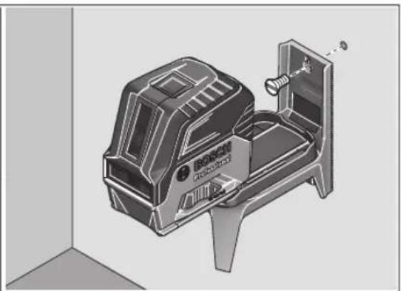
natural_image
3D technical illustration of a Bosch industrial machine with internal components and mounting bracket (no text or symbols)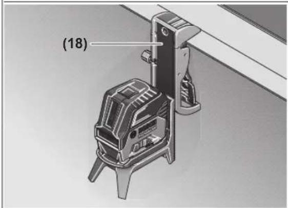
natural_image
Technical illustration of a mechanical device with mounting feet and warning symbol (no readable text or labels)5
Bosch Power Tools 1 609 92A 8E9 | (20.03.2023)
6
natural_image
3D perspective diagram of a room with a camera and tripod, labeled B2 and C2 (no text or symbols on the diagram itself)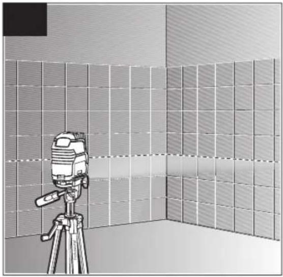
natural_image
Illustration of a camera mounted on a tripod in a tiled room (no text or symbols)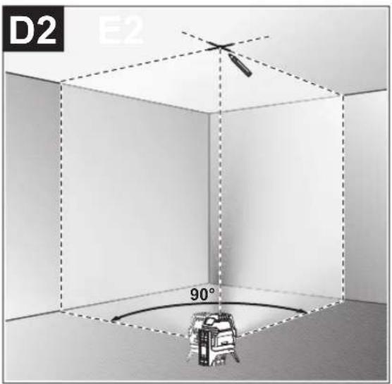
natural_image
Interior view of a room with a ceiling-mounted device and a vertical dashed line, no visible text or symbols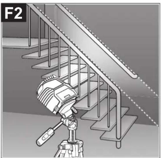
natural_image
Illustration of a mechanical device mounted on a tripod against a staircase (no text or symbols)1 609 92A 8E9 | (20.03.2023) Bosch Power Tools
natural_image
Interior view of a room with ceiling-mounted fixtures and a mounted device (no visible text or symbols)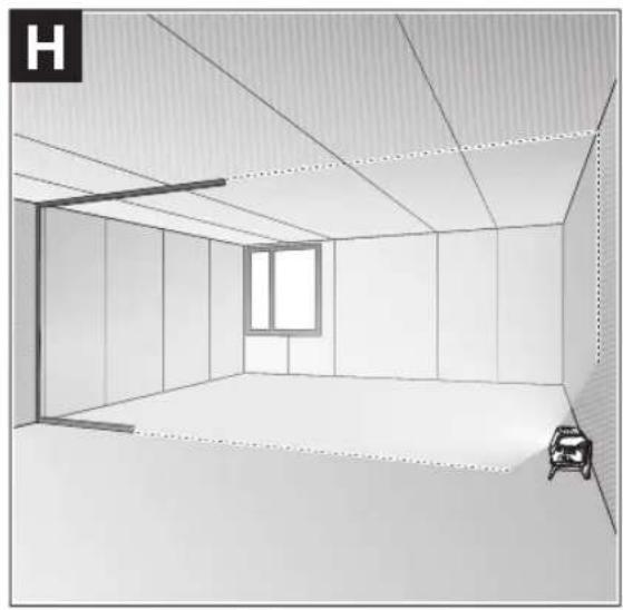
natural_image
Interior view of a room with ceiling, window, and furniture (no text or symbols)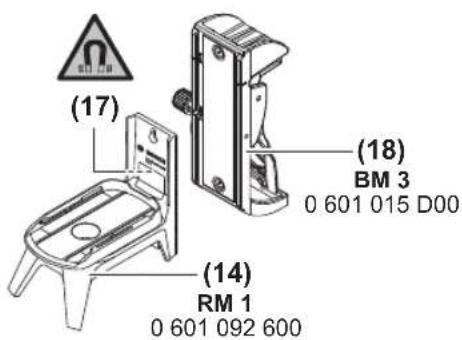
natural_image
Isometric line drawing of a multi-compartment container or tray structure with no text or symbols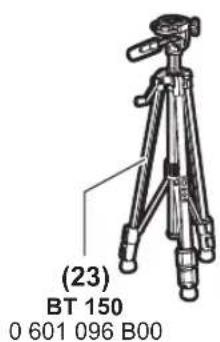
Deutsch
Sicherheitshinweise

www.bosch-pt.com/serviceaddresses
Entsorgung
All instructions must be read and observed in order for the measuring tool to function safely. The safeguards integrated into the measuring tool may be compromised if the
measuring tool is not used in accordance with these instructions. Never make warning signs on the measuring tool unrecognisable. SAVE THESE INSTRUCTIONS FOR FUTURE REFERENCE AND INCLUDE THEM WITH THE MEASURING TOOL WHEN TRANSFERRING IT TO A THIRD PARTY.
▶ Warning! If operating or adjustment devices other than those specified here are used or other procedures are carried out, this can lead to dangerous exposure to radiation.
The measuring tool is delivered with a laser warning sign (marked in the illustration of the measuring tool on the graphics page).
▶ If the text of the laser warning label is not in your national language, stick the provided warning label in your national language over it before operating for the first time.

Do not direct the laser beam at persons or animals and do not stare into the direct or reflected laser beam yourself. You could blind somebody, cause accidents or damage your eyes.
▶ If laser radiation hits your eye, you must close your eyes and immediately turn your head away from the beam.
▶ Do not make any modifications to the laser equipment.
▶ Do not use the laser goggles (accessory) as protective goggles. The laser goggles make the laser beam easier to see; they do not protect you against laser radiation.
▶ Do not use the laser goggles (accessory) as sunglasses or while driving. The laser goggles do not provide full UV protection and impair your ability to see colours.
▶ Have the measuring tool serviced only by a qualified specialist using only original replacement parts. This will ensure that the safety of the measuring tool is maintained.
▶ Do not let children use the laser measuring tool unsupervised. They could unintentionally blind themselves or other persons.
▶ Do not use the measuring tool in explosive atmospheres which contain flammable liquids, gases or dust. Sparks may be produced inside the measuring tool, which can ignite dust or fumes.

Keep the measuring tool and the magnetic accessories away from implants and other medical devices, e.g. pacemakers or insulin pumps. The magnets inside the measuring tool and accessories generate a field that can impair the function of implants and medical devices.
▶ Keep the measuring tool and the magnetic accessories away from magnetic data storage media and magnetically sensitive devices. The effect of the magnets inside the measuring tool and accessories can lead to irreversible data loss.
Product Description and Specifications
Please observe the illustrations at the beginning of this operating manual.
Intended Use
The measuring tool is intended for determining and checking horizontal and vertical lines and plumb points.
The measuring tool is suitable for indoor and outdoor use. This product is a consumer laser product in accordance with EN 50689.
Product Features
The numbering of the product features shown refers to the illustration of the measuring tool on the graphic page.
(1) Laser beam outlet aperture
(2) Battery warning
(3) Pendulum lock indicator
(4) Laser point operating mode button
(5) Laser line operating mode button
(6) Battery compartment cover
(7) Locking mechanism of the battery compartment cover
(8) Guide groove
(9) On/off switch
(10) 1/4" tripod mount
(11) 5/8" tripod mount
(12) Serial number
(13) Laser warning label
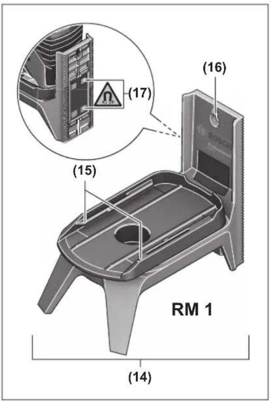
(14) Rotating mount (RM 1)
(15) Guide rail
(16) Fastening slot
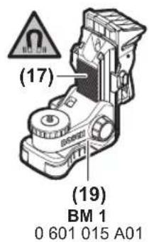
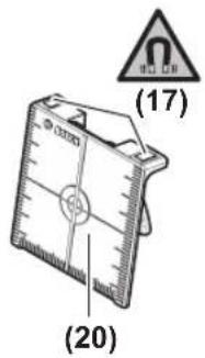
(17) Magnet
(18) Ceiling clip ^a)
(19) Universal holder (BM 1) ^4
(20) Laser target plate ^a)
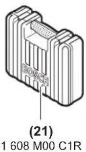
(21) Case ^a)
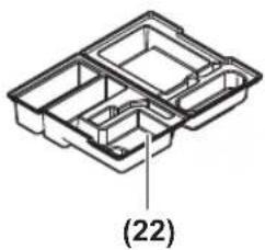
(22) Inlay ^a)
(23) Tripod (BT 150) ^a)
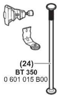
(24) Telescopic shaft (BT 350) ^a)
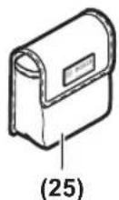
(25) Protective bag ^a)
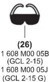
(26) Laser viewing glasses ^a)
a) Accessories shown or described are not included with the product as standard. You can find the complete selection of accessories in our accessories range.
Technical Data
| Point and line laser GCL 2-15 GCL 2-15 G | |
| Article number | 3 601 K66 E.. 3 601 K66 J.. |
| Working rangeA) | |
| – Laser line 15 m 15 m | |
| – Laser point facing up 10 m 10 m | |
| – Laser point facing down 10 m 10 m | |
| Levelling accuracyB)(C) | |
18 | English
Point and line laser GCL 2-15 GCL 2-15 G
| – Laser lines ±0.3 mm/m ±0.3 mm/m | ||
| – Laser points ±0.7 mm/m ±0.7 mm/m | ||
| Typical self-levelling range ±4° ±4° | ||
| Typical levelling time < 4 s < 4 s | ||
| Operating temperature -10 °C to +50 °C -10 °C to +50 °C | ||
| Storage temperature -20 °C to +70 °C -20 °C to +70 °C | ||
| Max. altitude 2000 m 2000 m | ||
| Relative air humidity max. 90 % 90 % | ||
| Pollution degree according to IEC 61010-1 | 2D) | 2D) |
| Laser class 2 | 2 | |
| Laser line | ||
| – Laser type | < 1 mW, 630–650 nm | < 10 mW, 500–540 nm |
| – Colour of the laser beam | Red | Green |
| – C6 | 1 | 10 |
| – Divergence | 0.5 mrad (full angle) | 50 × 10 mrad (full angle) |
| Laser point | ||
| – Laser type | < 1 mW, 630–650 nm | < 1 mW, 630–650 nm |
| – Colour of the laser beam | Red | Red |
| – C6 | 1 | 1 |
| – Divergence | 0.8 mrad (full angle) | 0.8 mrad (full angle) |
| Tripod mount | 1/4", 5/8" | 1/4", 5/8" |
| Batteries | 3 × 1.5 V LR6 (AA) | 3 × 1.5 V LR6 (AA) |
| Operating duration in operating mode8) | ||
| – Cross-line and point mode | 6 h | 6 h |
| – Cross-line mode | 8 h | 8 h |
| – Line and point mode | 12 h | 10 h |
| – Line mode | 16 h | 12 h |
| – Point mode | 22 h | 22 h |
| Weight according to EPTA-Proced-ure 01:2014 | 0.49 kg | 0.49 kg |
| Dimensions (length × width × height) | ||
| – Without rotating mount | 112 × 55 × 106 mm | 112 × 55 × 106 mm |
| – With rotating mount | 132 × 81 × 163 mm | 132 × 81 × 163 mm |
| Protection rating | IP54 (dust and splash-proof) | IP54 (dust and splash-proof) |
A) The working range may be reduced by unfavourable environmental conditions (e.g. direct sunlight).
B) At 20-25°C
C) The values stated presuppose normal to favourable environmental conditions (e.g. no vibration, no fog, no smoke, no direct sunlight). Extreme fluctuations in temperature can cause deviations in accuracy.
D) Only non-conductive deposits occur, whereby occasional temporary conductivity caused by condensation is expected.
The serial number (12) on the type plate is used to clearly identify your measuring tool.
Assembly
Inserting/Changing the batteries
It is recommended that you use alkaline manganese batteries to operate the measuring tool.
To open the battery compartment cover (6), press the locking mechanism (7) and lift open the battery compartment cover. Insert the batteries.
When inserting the batteries, ensure that the polarity is correct according to the illustration on the inside of the battery compartment.
If the batteries become weak, the battery warning indicator (2) will flash green. The laser lines will also flash for approximately five seconds every ten minutes. The measuring tool can still be operated for approximately one hour after the first flash. If the batteries drain completely, the laser lines will flash one more time just before automatic shut-off.
Always replace all the batteries at the same time. Only use batteries from the same manufacturer and which have the same capacity.
▶ Take the batteries out of the measuring tool when you are not using it for a prolonged period of time. The batteries can corrode and self-discharge during prolonged storage in the measuring tool.
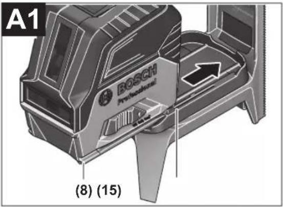
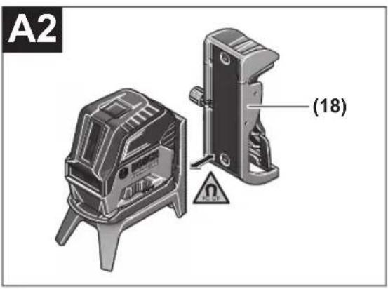
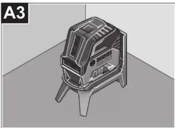
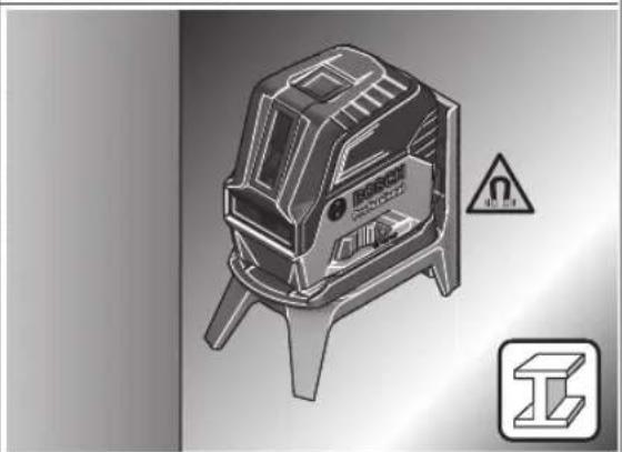
Working with the RM 1 rotating mount (see figures A1–A3)
You can use the rotating mount (14) to rotate the measuring tool 360° around a central, always visible plumb point. This enables you to set up the laser lines without having to change the position of the measuring tool.
Place the measuring tool with the guide groove (8) on the guide rail (15) of the rotating mount (14) and slide the measuring tool all the way onto the platform.
To disconnect the measuring tool, pull it off the rotating mount in the opposite direction.
Rotating mount positioning options:
- Standing on a flat surface,
- Screwed to a vertical surface,
- On metallic ceiling strips using the ceiling clip (18),
- On metallic surfaces using the magnets (17).
▶ Keep your fingers away from the rear side of the magnetic accessory while attaching the accessory to surfaces. The strong pulling force of the magnets may jam your fingers.
Operation
Starting Operation
▶ Protect the measuring tool from moisture and direct sunlight.
▶ Do not expose the measuring tool to any extreme temperatures or fluctuations in temperature. For example, do not leave it in a car for extended periods of time. If it has been subjected to significant fluctuations in temperature, first allow the measuring tool to adjust to the ambient temperature and then always carry out an accuracy check before continuing work (see "Accuracy Check of the Measuring Tool", page 21).
The precision of the measuring tool may be compromised if exposed to extreme temperatures or fluctuations in temperature.
▶ Avoid substantial knocks to the measuring tool and avoid dropping it. Always carry out an accuracy check before continuing work if the measuring tool has been
subjected to severe external influences (see "Accuracy Check of the Measuring Tool", page 21).
▶ Switch the measuring tool off when transporting it. The pendulum unit is locked when the tool is switched off, as it can otherwise be damaged by big movements.
Switching On/Off
To switch on the measuring tool, slide the on/off switch (9) to the on position (for working with the pendulum lock) or to the on position (for working with automatic levelling). As soon as it is switched on, the measuring tool emits laser beams from the outlet apertures (1).
▶ Do not direct the laser beam at persons or animals and do not stare into the laser beam yourself (even from a distance).
To switch off the measuring tool, slide the on/off switch (9) to the Off position. The pendulum unit is locked when the tool is switched off.
▶ Never leave the measuring tool unattended when switched on, and ensure the measuring tool is switched off after use. Others may be blinded by the laser beam.
If the maximum permitted operating temperature of 50^ C is exceeded, the tool shuts down to protect the laser diode. Once it has cooled down, the measuring tool is operational again and can be switched back on.
Automatic Shut-Off
If no button on the measuring tool is pressed for approx. 120 min, the measuring tool will automatically switch itself off to preserve battery life.
To switch the measuring tool back on after it has been automatically switched off, you can either slide the on/off switch (9) to the "Off" position first and then switch the measuring tool back on, or press either the laser point mode button (4) or the laser line mode button (5).
Temporarily Deactivating Automatic Shut-Off
To deactivate the automatic shut-off function, hold down the laser line mode button (5) for at least 3 s (with the measuring tool switched on). If the automatic shut-off function is deactivated, the laser beams will flash briefly as confirmation.
Note: If the operating temperature exceeds 45 °C, automatic shut-off can no longer be deactivated.
To activate the automatic shut-off function, switch the measuring tool off and on again.
Setting the Operating Mode
The measuring tool has several operating modes, which you can switch between at any time:
- Cross-line and point mode: The measuring tool generates a horizontal and a vertical laser line as well as two vertical laser points, one facing up, the other down. The laser lines cross at a 90^ angle.
- Horizontal line mode: The measuring tool generates a horizontal laser line in front of it.
20 | English
- Vertical line mode: The measuring tool generates a vertical laser line in front of it.
Positioning the measuring tool in the room displays the vertical laser line on the ceiling beyond the top laser point.
If the measuring tool is positioned directly against a wall,
the vertical laser line almost encircles the entire space (360° line).
- Point mode: The measuring tool generates two vertical laser points, one facing up, the other down.
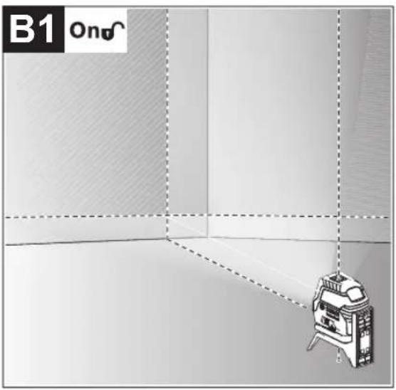
All operating modes, apart from point operation, can be selected with both automatic levelling or the pendulum lock.
Working with Automatic Levelling
| Sequence of actions Horizontal line | Vertical line mode | Point mode Pendulum lock indicator (3) | Figure | |
| mode | ||||
| On/off switch (9) in position " [IMAGE]" | ●●● | ☐ | B1 | |
| Cross-line mode | ||||
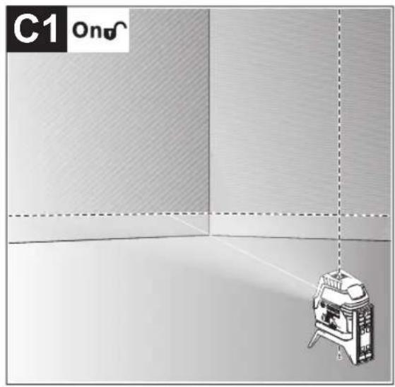
 | Press the laser line operating mode button (5) once | ●-● | ☐ | C1 |
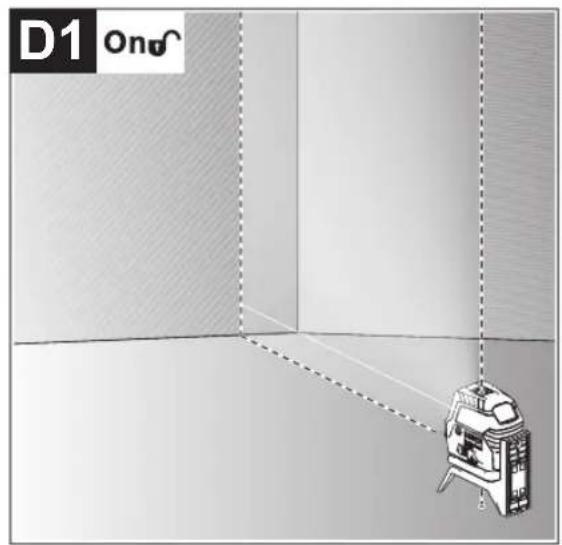
| Press the laser line operating mode button (5) twice | -●● | ☐ | D1 | |
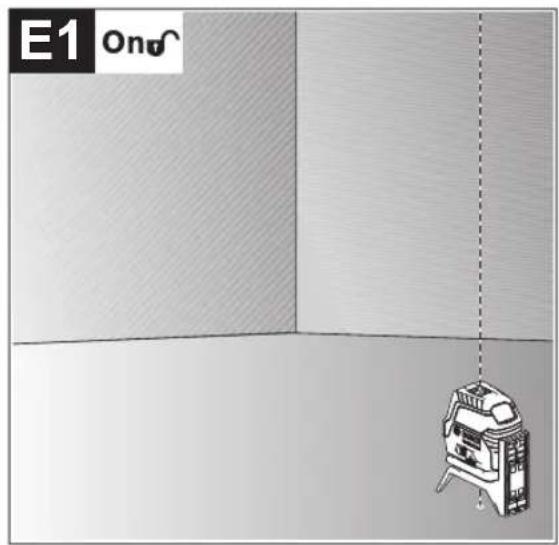
| Press the laser line operating mode button (5) three times | --● | ☐ | E1 | |
| Press the laser line operating mode button (5) four times | ●●● | ☐ | B1 | |
| Cross-line mode | ||||
Point mode can be activated or deactivated regardless of the line mode setting:
| Press the laser point operating mode button (4) once | ●/- ●/--- | ☐ |
| Press the laser point operating mode button (4) twice | ●/- ●/- ● | ☐ |
If the measuring tool is outside of the self-levelling range, the laser lines and/or points will flash quickly.
If, during work with automatic levelling, you switch to "working with pendulum lock" mode (on/off switch (9) in position
On), the first combination option of this mode's indicators is always activated.
Working with the pendulum lock
| Sequence of actions Horizontal line | Vertical line mode | Point mode Pendulum lock indicator (3) | Figure | ||
| mode | |||||
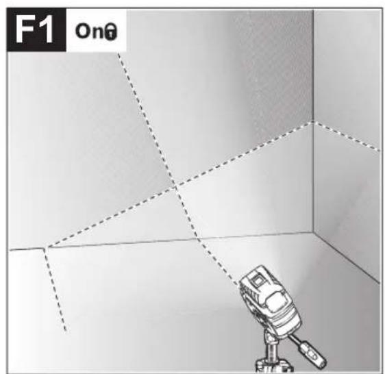
| On/off switch (9) in position "On" | ●●- |  | F1 | ||
| Cross-line mode | Red | ||||
 | Press the laser line operating mode button (5) once | ●-- |  | Red | |
| Press the laser line operating mode button (5) twice | --●- | [0H8B] | Red | ||
| Press the laser line operating mode button (5) three times | ●●- | [4HX6] | F1 | ||
| Cross-line mode | Red | ||||
The laser lines continuously flash slowly in "working with the pendulum lock" mode.
If, during work with pendulum lock, you switch to "working with automatic levelling" mode (on/off switch (9) in position
On), the first combination option of this mode's indicators is always activated.
Automatic Levelling
Working with Automatic Levelling (see figures B1–E1)
Position the measuring tool on a level, firm surface or attach it to the rotating mount (14).
For work with automatic levelling, slide the on/off switch (9) to the "on" position.
The automatic levelling function automatically levels irregularities within the self-levelling range of ±4^ . The measuring tool has been levelled as soon as the laser beams stop flashing.
If automatic levelling is not possible, e.g. because the surface on which the measuring tool stands deviates by more than 4^ from the horizontal plane, the laser beams will flash quickly.
If this is the case, set up the measuring tool in a level position and wait for the self-levelling to take place. As soon as the measuring tool is within the self-levelling range of ±4^ , the laser beams will light up continuously.
In case of ground vibrations or position changes during operation, the measuring tool is automatically levelled again. Upon levelling, check the position of the laser beams with regard to the reference points to avoid errors arising from a change in the measuring tool's position.
Working with a pendulum lock (see figure F1)
For work with the pendulum lock, slide the on/off switch (9) to the "on" position. The pendulum lock indicator (3) lights up red and the laser lines continuously flash slowly.
For work with the pendulum lock, automatic levelling is switched off. You can hold the measuring tool freely in your hand or place it on a sloping surface. This means that the laser beams are no longer levelled and no longer necessarily run perpendicular to one another.
Accuracy Check of the Measuring Tool
Influences on Accuracy
The largest influence is exerted by the ambient temperature. In particular, temperature differences that occur from the ground upwards can refract the laser beam.
In order to minimise thermal influences resulting from heat rising from the floor, it is recommended that you use the measuring tool on a tripod. In addition, position the measuring tool in the centre of the work surface, wherever this is possible.
In addition to external influences, device-specific influences (e.g. falls or heavy impacts) can also lead to deviations. For this reason, check the levelling accuracy each time before beginning work.
First check the height accuracy and levelling accuracy of the horizontal laser line, then the levelling accuracy of the vertical laser line.
Should the measuring tool exceed the maximum deviation during one of the tests, please have it repaired by a Bosch after-sales service.
Checking the Height Accuracy of the Horizontal Line
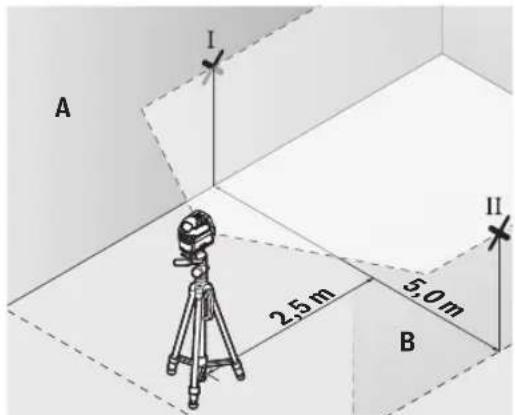
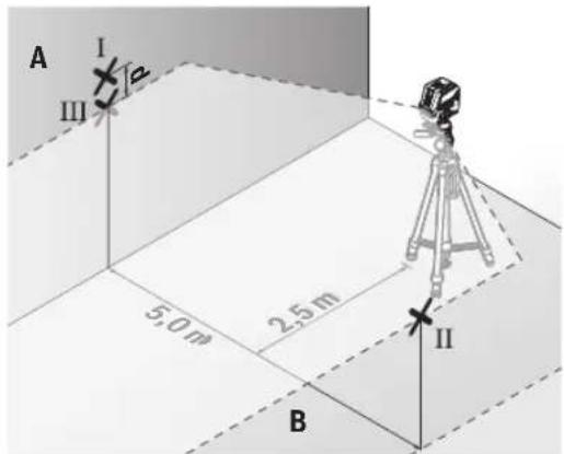
For this check, you will need a free measuring distance of 5 m on firm ground between two walls (designated A and B).
- Mount the measuring tool close to wall A on a tripod, or place it on a firm, level surface. Switch on the measuring tool. Select cross-line mode with automatic levelling.
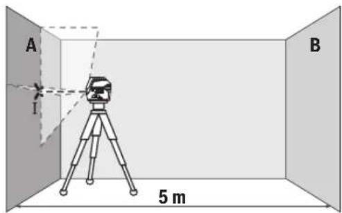
- Aim the laser at the closer wall A and allow the measuring tool to level in. Mark the middle of the point at which the laser lines cross on the wall (point I).
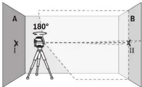
- Turn the measuring tool 180^ , allow it to level in and mark the point where the laser lines cross on the opposite wall B (point II).
- Position the measuring tool – without rotating it – close to wall B, switch it on and allow it to level in.
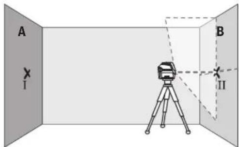
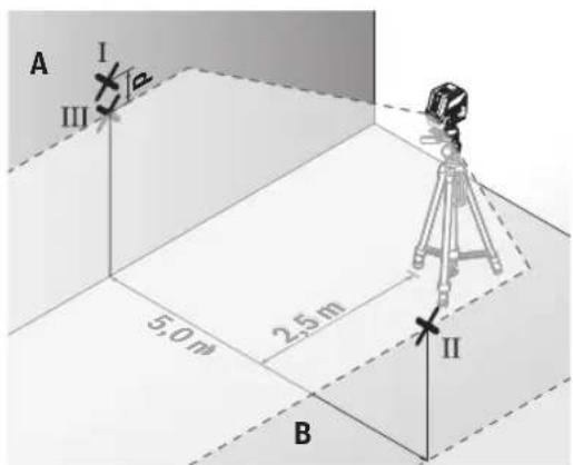
- Align the height of the measuring tool (using the tripod or by placing objects underneath as required) so that the point where the laser lines cross exactly hits the previously marked point II on wall B.
22 | English
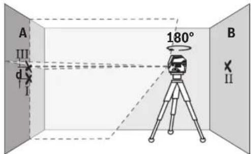
- Turn the measuring tool 180^ without adjusting the height. Aim it at wall A such that the vertical laser line runs through the already marked point I. Allow the measuring tool to level in and mark the point where the laser lines cross on wall A (point III).
- The discrepancy d between the two marked points I and III on wall A reveals the actual height deviation of the measuring tool.
The maximum permitted deviation on the measuring distance of 2 × 5 m = 10 m is as follows:
10 m × ±0.3 mm/m = ±3 mm. The discrepancy d between points I and III must therefore amount to no more than 3 mm.
Checking the Level Accuracy of the Horizontal Line
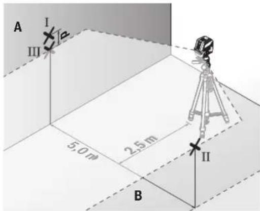
For this check, you will need a free area of 5 × 5 m.
- Mount the measuring tool in the middle between walls A and B on a tripod, or place it on a firm, level surface. Select horizontal line mode with automatic levelling and allow the measuring tool to level in.
- At a distance of 2.5 m from the measuring tool, mark the centre of the laser line on both walls (point I on wall A and point II on wall B).
- Set up the measuring tool at a 5 m distance and rotated by 180^ and allow it to level in.
- Align the height of the measuring tool (using the tripod or by placing objects underneath as required) so that the
centre of the laser line exactly hits the previously marked point II on wall B.
- Mark the centre of the laser line on wall A as point III (vertically above or below point I).
- The discrepancy d between the two marked points I and III on wall A reveals the actual horizontal deviation of the measuring tool.
The maximum permitted deviation on the measuring distance of 2 × 5 m = 10 m is as follows:
10 m × ±0.3 mm/m = ±3 mm. The discrepancy d between points I and III must therefore amount to no more than 3 mm.
Checking the Level Accuracy of the Vertical Line
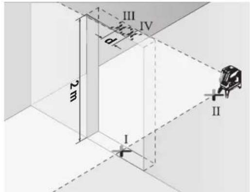
For this check, you will need a door opening (on solid ground) which has at least 2.5 m of space either side of the door.
- Place the measuring tool 2.5m away from the door opening on a firm, flat surface (not on a tripod). Select vertical line mode with automatic levelling. Aim the laser line at the door opening and allow the measuring tool to level in.
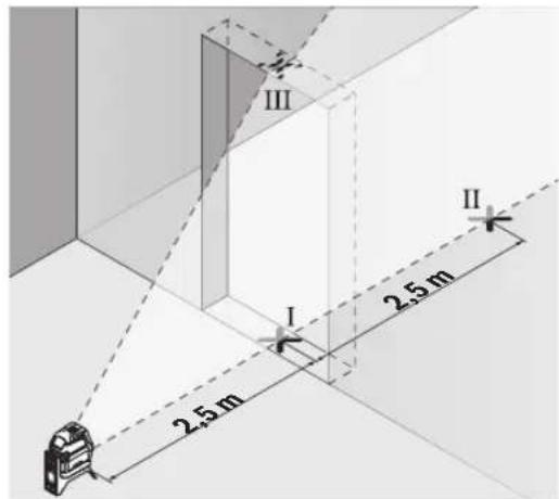
- Mark the centre of the vertical laser line on the floor of the door opening (point I), 5 m away on the other side of the door opening (point II) and on the upper edge of the door opening (point III).
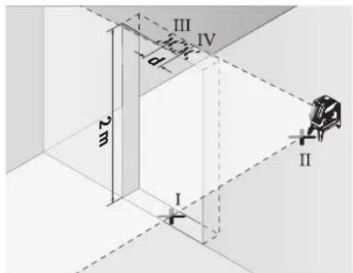
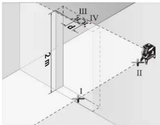
- Rotate the measuring tool 180^ and position it on the other side of the door opening, directly behind point II. Allow the measuring tool to level in and align the vertical laser line in such a way that its centre passes through points I and II exactly.
- Mark the centre of the laser line on the upper edge of the door opening as point IV.
- The discrepancy d between the two marked points III and IV reveals the actual vertical deviation of the measuring tool.
- Measure the height of the door opening.
You can calculate the maximum permitted deviation as follows:
Doubled height of the door opening × 0.3 mm/m Example: At a door opening height of 2 m, the maximum deviation amounts to
2 × 2 m × ± 0.3 mm/m = ± 1.2 mm . The points III and IV must therefore be no further than 1.2 mm from each other.
Checking Plumb Accuracy
For this check, you will need a clear measuring space on firm ground with a distance of approx. 5 m between the floor and the ceiling.
- Mount the measuring tool onto the rotating mount (14) and place it on the floor. Select point mode and allow the measuring tool to level in.
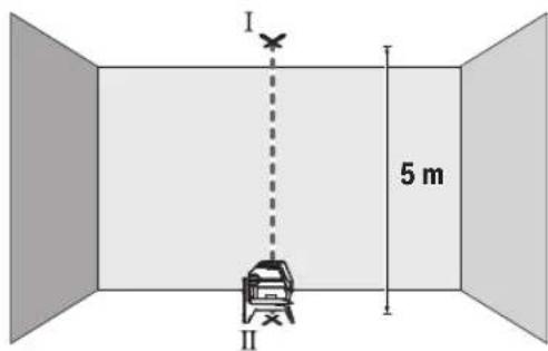
- Mark the centre of the top laser point on the ceiling (point I). Also mark the centre of the bottom laser point on the floor (point II).
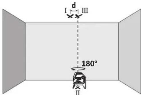
- Turn the measuring tool by 180^ . Position it so that the centre of the bottom laser point falls onto the marked point II. Allow the measuring tool to level in. Mark the centre of the top laser point (point III).
- The discrepancy d between the two marked points I and III on the ceiling reveals the actual deviation of the measuring tool from the vertical plane.
You can calculate the maximum permitted deviation as follows:
Doubled distance between floor and ceiling × 0.7 mm/m Example: At a floor-to-ceiling distance of 5 m, the maximum deviation amounts to
2 × 5 m × ± 0.7 mm/m = ± 7 mm . The points I and III must therefore be no further than 7 mm from each other.
Working Advice
▶ Only the centre of the laser point or laser line must be used for marking. The size of the laser point/the width of the laser line changes depending on the distance.
Working with the Tripod (Accessory)
A tripod offers a stable, height-adjustable support surface for measuring. Place the measuring tool with the 1/4" tripod mount (10) on the thread of the tripod (23) or a conventional camera tripod. Use the 5/8" tripod mount (11) to secure the measuring tool on a conventional building tripod.
Tighten the measuring tool using the locking screw of the tripod.
Roughly align the tripod before switching on the measuring tool.
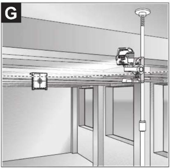
Securing with the universal holder (accessory) (see figure G)
You can secure the measuring tool, for example, on vertical surfaces or magnetisable materials using the universal holder (19). The universal holder is also suitable for use as a floor stand and facilitates the height adjustment of the measuring tool.
- Keep your fingers away from the rear side of the magnetic accessory while attaching the accessory to surfaces. The strong pulling force of the magnets may jam your fingers.
Roughly align the universal holder (19) before switching on the measuring tool.
Working with the Laser Target Plate (see figure G)
The laser target plate (20) improves visibility of the laser beam in unfavourable conditions and at greater distances.
The reflective surface of the laser target plate (20) improves visibility of the laser line. The transparent surface enables the laser line to be seen from behind the laser target plate.
Laser Goggles (Accessory)
The laser goggles filter out ambient light. This makes the light of the laser appear brighter to the eye.
▶ Do not use the laser goggles (accessory) as protective goggles. The laser goggles make the laser beam easier to see; they do not protect you against laser radiation.
▶ Do not use the laser goggles (accessory) as sunglasses or while driving. The laser goggles do not provide full UV protection and impair your ability to see colours.
24 | Français
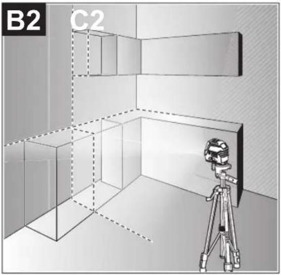
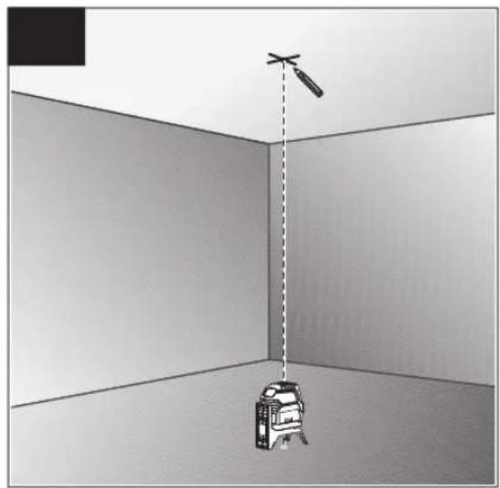
Example Applications (see figures B2-F2, G and H)
Examples of possible applications for the measuring tool can be found on the graphics pages.
Maintenance and Service
Maintenance and Cleaning
Keep the measuring tool clean at all times.
Never immerse the measuring tool in water or other liquids.
Wipe off any dirt using a damp, soft cloth. Do not use any detergents or solvents.
The areas around the outlet aperture of the laser in particular should be cleaned on a regular basis. Make sure to check for lint when doing this.
After-Sales Service and Application Service
Our after-sales service responds to your questions concerning maintenance and repair of your product as well as spare parts. You can find explosion drawings and information on spare parts at: www.bosch-pt.com
The Bosch product use advice team will be happy to help you with any questions about our products and their accessories.
In all correspondence and spare parts orders, please always include the 10-digit article number given on the nameplate of the product.
Malaysia
Robert Bosch Sdn. Bhd.(220975-V) PT/SMY
No. 8A, Jalan 13/6
46200 Petaling Jaya
Selangor
Tel.: (03) 79663194
Toll-Free: 1800 880188
Fax: (03) 79583838
E-Mail: kiathoe.chong@my.bosch.com
www.bosch-pt.com.my
Great Britain
Robert Bosch Ltd. (B.S.C.)
P.O. Box 98
Broadwater Park
North Orbital Road
Denham Uxbridge
UB 9 5HJ
At www.bosch-pt.co.uk you can order spare parts or arrange the collection of a product in need of servicing or repair.
Tel. Service: (0344) 7360109
E-Mail: boschservicecentre@bosch.com
You can find further service addresses at:
www.bosch-pt.com/serviceaddresses
Disposal
Measuring tools, accessories and packaging should be recycled in an environmentally friendly manner.

Do not dispose of measuring tools or batteries with household waste.
Only for EU countries:
According to the Directive 2012/19/EU on waste electrical and electronic equipment and its transposition into national law, measuring tools that are no longer usable, and, according to the Directive 2006/66/EC, defective or drained batteries must be collected separately and disposed of in an environmentally correct manner.
If disposed incorrectly, waste electrical and electronic equipment may have harmful effects on the environment and human health, due to the potential presence of hazardous substances.
Only for United Kingdom:
According to The Waste Electrical and Electronic Equipment Regulations 2013 (SI 2013/3113) (as amended) and the Waste Batteries and Accumulators Regulations 2009 (SI 2009/890) (as amended), products that are no longer usable must be collected separately and disposed of in an environmentally friendly manner.
Français
Robert Bosch Morocco SARL
53, Rue Lieutenant Mahroud Mohamed
20300 Casablanca
Tel.: +212 5 29 31 43 27
E-Mail : sav.outillage@ma.bosch.com
France
Robert Bosch (France) S.A.S.
www.bosch-pt.com/serviceaddresses
Calle Robert Bosch No. 405
www.bosch-pt.com/serviceaddresses
Eliminación
www.bosch-pt.com/serviceaddresses
Eliminação
www.bosch-pt.com/serviceaddresses
Smaltimento
64 | Nederlands
www.bosch-pt.com/serviceaddresses
Afvalverwijdering
(10) Stativholder 1/4"
(11) Stativholder 5/8"
(12) Serienummer
(13) Laser-advarselsskilt
(14) Drejeholder (RM 1)
(15) Føringsskinne
(16) Monteringslanghul
(17) Magnet
(18) Loftsklemme ^a)
(19) Universalholder (BM 1) ^a)
(20) Laser-måltavle ^a)
(21) Kuffert ^a)
(22) Indlæg ^a)
(23) Stativ (BT 150) ^a)
(24) Teleskopstang (BT 350) ^a)
(25) Beskyttelsestaske ^a)
Bosch Service Center
Telegrafvej 3
2750 Ballerup
På www.bosch-pt.dk kan der online bestilles reservedele eller oprettes en reparations ordre.
Tlf. Service Center: 44898855
Fax: 44898755
E-Mail: vaerktoej@dk.bosch.com
www.bosch-pt.com/serviceaddresses
Bortskaffelse
Bosch Service Center
Telegrafvej 3
2750 Ballerup
Danmark
Tel.: (08) 7501820 (inom Sverige)
Fax: (011) 187691
www.bosch-pt.com/serviceaddresses
Avfallshantering
www.bosch-pt.com/serviceaddresses
Kassering
www.bosch-pt.com/serviceaddresses
Hävitys
www.bosch-pt.com/serviceaddresses
Απόσυροη
(14) Dönen platform (RM 1)
(15) Kilavuz ray
(16) Montaj deligi
(17) Miknatis
(18) Üst braket ^a)
www.bosch-pt.com/serviceaddresses
Tasfiye
Robert Bosch Sp. z o.o.
www.bosch-pt.com/serviceaddresses
Utylizacja odpadów
Bosch Service Center PT
K Vápence 1621/16
692 01 Mikulov
www.bosch-pt.com/serviceaddresses
Likvidace
www.bosch-pt.com/serviceaddresses
Likvidácia
www.bosch-pt.com/serviceaddresses
Hulladékkezelés
www.bosch-pt.com/serviceaddresses
Утилизация
www.bosch-pt.com/serviceaddresses
Утилізація
www.bosch-pt.com/serviceaddresses
Кәдеге жарату
(19) grades (BM 1) ^a)
sā dāgān bāgāsān lūsmān nōbūfēngdāgān gāssyāgān 3mān bāmāsāmān gō sā gāsāmāgān 03nm bāgāmāgān gōu māgāndu. dāu dāgāgā, māsī lūsmān nōbūfēngdāgān dāgān u sāfēmāsāgān bāgāmāgān gōu māsāmādūn ±4°, māsāgāmān lūn zgān nūyāgāgā gīyāgāgī bāsmādūn.
www.bosch-pt.com/serviceaddresses
ΥΩΝΟΛΟΥΣΗΣ
Service scule electrice
Strada Horia Măcelariu Nr. 30-34, sector 1
013937 Bucureşti
www.bosch-pt.com/serviceaddresses
Eliminarea
Service scule electrice
Strada Horia Măcelariu Nr. 30-34, sector 1
013937 Bucureşti, România
www.bosch-pt.com/bg/bg/
www.bosch-pt.com/serviceaddresses
Бракуване
www.bosch-pt.com/serviceaddresses
Отстранување
- Usmerite laser na bliski zid A i pustite da se merni alat niveliše. Označite sredinu tačke na kojoj se laserske linije na zidu ukrštaju (tačka I).
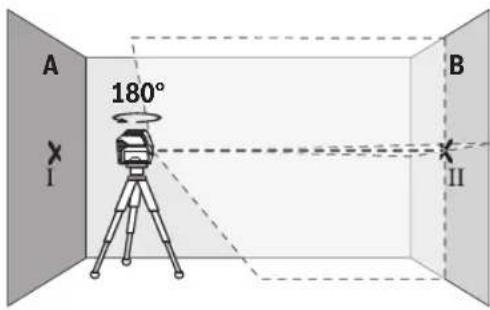
- Okrenite merni alat za 180°, pustite da se niveliše i označite tačku ukrštanja laserskih linija na suprotnom zidu B (tačka II).
- Stavite merni alat - bez okretanja - blizu zida B, uključite ga i pustite da se niveliše.
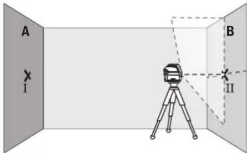
- Merni alat usmerite u vis tako (pomoću stativa ili po potrebi podmetanjem), da tačka ukrštanja laserskih linija tačno pogađa prethodno označenu tačku II na zidu B.
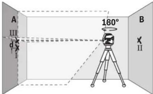
- Merni alat okrenite za 180°, a da ne pomerate visinu. Usmerite ga prema zidu A, tako da vertikalna laserska linija prolazi kroz već označenu tačku I. Pustite merni alat da se niveliše i označite tačku ukrštanja laserskih linija na zidu A (tačka III).
- Postavite merni alat za 180° okrenut na 5 m udaljenosti i iznivelišite ga.
- Merni alat usmerite uvis tako (pomoću stativa ili po potrebi podmetanjem) da sredina laserske linije tačno pogada prethodno označenu tačku II na zidu B.
– Označite na zidu A sredinu laserske linije kao tačku III (vertikalno iznad odn. ispod tačke I). - Razlika d između obe označene tačke I i III na zidu A predstavlja stvarno odstupanje mernog alata od horizontale.
Na mernoj deonici od 2 × 5 m = 10 m maksimalno dozvoljeno odstupanje iznosi:
10 m × ±0,3 mm/m = ±3 mm. Razlika d između tačaka I i III prema tome sme da iznosi maksimalno 3 mm.
216 | Srpski
Kontrola tačnosti nivelisanja vertikalne linije
Za kontrolu potreban Vam je otvor od vrata, kod kojih (na čvrstoj zemlji) sa svake strane vrata ima najmanje 2,5 m prostora.
- Postavite merni alat na 2,5 m rastojanja od otvora vrata na čvrstu radnu podlogu (ne na stativ). Izaberite vertikalni linijski režim rada sa automatskim nivelisanjem. Usmerite lasersku liniju na otvor vrata i iznivelišite merni alat.
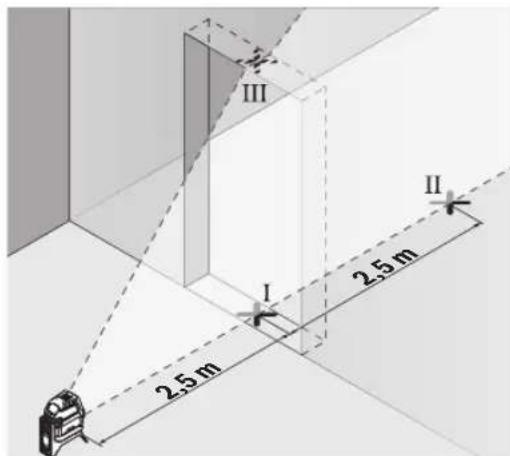
- Označite sredinu vertikalne laserske linije na podu otvora za vrata (tačka I), na razdaljini od 5 m od druge strane otvora za vrata (tačka II) kao i na gornjoj ivici otvora za vrata (tačka III).
www.bosch-pt.com/serviceaddresses
Uklanjanje dubreta
Merni alati, pribor i ambalaža treba da se uključe u reciklažu koja odgovara zaštiti čovekove okoline.

Merne alate i baterije nemojte bacati u kućni otpad!
Samo za EU-zemlje:
Prema evropskoj direktivi 2012/19/EU o starim električnim i elektronskim uređajima i njenoj primeni u nacionalnom pravu, merni alati koji se više ne mogu koristiti, a prema evropskoj direktivi 2006/66/EC akumulatori/baterije koje su u kvaru ili istrošene moraju se odvojeno sakupljati i uključiti u reciklažu koja ispunjava ekološke uslove.
- Na oddaljenosti 2,5 m od merilne naprave na obeh stenah označite sredino laserske linije (točka I na steni A in točka II na steni B).
www.bosch-pt.com/serviceaddresses
Odlaganje
Merilne naprave, pribor in embalažo oddajte v okolju prijazno recikliranje.

- Na udaljenosti 2,5 m od mjernog alata označite na oba zida sredinu linije lasera (točka I na zidu A i točka II na zidu B).
- Postavite mjerni alat okrenut za 180° na udaljenosti 5 m i iznivelirajte ga.
- Mjerni alat usmjerite po visini (pomoću stativa ili eventualno podlaganjem) tako da sredina linije lasera točno udara na prethodno označenu točku II na zidu B.
- Na zidu A označite sredinu linije lasera kao točku III (okomito iznad odn. ispod točke I).
- Razlika d obje označene točke I i III na zidu A daje stvarno odstupanje miernog alata od horizontale.
- Označite sredinu okomite linije lasera na dnu otvora vrata (točka I), na udaljenosti 5 m na drugoj strani otvora vrata (točka II) kao i na gornjem rubu otvora vrata (točka III).
- Okrenite mjerni alat za 180°. Pozicionirajte ga tako da sredina donje točke lasera pada na već označenu točku II. Iznivelirajte mjerni alat. Označite sredinu gornje točke lasera (točka III). - Razlika d obje označene točke I i III na stropu daje stvarno odstupanje mjernog alata od okomice.
www.bosch-pt.com/serviceaddresses
Zbrinjavanje
Mjerne alate, pribor i ambalažu treba dovesti na ekološki prihvatljivo recikliranje.

Mjerne alate i baterije ne bacajte u kućni otpad!
Samo za zemlje EU:
U skladu s europskom Direktivom 2012/19/EU o električnim i elektroničkim starim uredajima i njihovom provedbom u nacionalno pravo neupotrebljivi mjerni alati i u skladu s europskom Direktivom 2006/66/EZ neispravne ili istrošene aku-baterije/baterije moraju se odvojeno sakupljati i dovesti na ekološki prihvatljivo recikliranje.
www.bosch-pt.com/serviceaddresses
Jäätmekäitlus
www.bosch-pt.com/serviceaddresses
www.bosch-pt.com/serviceaddresses
Šalinimas
www.bosch-pt.com/serviceaddresses
廃棄
www.bosch-pt.com/serviceaddresses
废弃处理
www.bosch-pt.com/serviceaddresses
廢棄物處理
www.bosch-pt.com/serviceaddresses
처리
www.bosch-pt.com/serviceaddresses
การกำจัดขยะ
Arkadia Green Park Tower G - 7th floor
Jl. Let. Jend. TB. Simatupang Kav.88 Jakarta 12520
Tel.: (021) 3005 5800
Fax: (021) 3005 5801
E-Mail: boschpowertools@id.bosch.com
www.bosch-pt.co.id
www.bosch-pt.com/serviceaddresses
Cara membuang
www.bosch-pt.com/serviceaddresses
Sự thải bổ
IOI I I I I I I I I I I I I I I I I I I I I I I I I I I I I I I I I I I I
Robert Bosch Morocco SARL
www.bosch-pt.com/serviceaddresses
www.bosch-pt.com/serviceaddresses
- Deutsch
- Sicherheitshinweise
- Entsorgung
- Product Description and Specifications
- Intended Use
- Product Features
- Assembly
- Inserting/Changing the batteries
- Working with the RM 1 rotating mount (see figures A1–A3)
- Operation
- Starting Operation
- Switching On/Off
- Automatic Shut-Off
- Temporarily Deactivating Automatic Shut-Off
- Setting the Operating Mode
- | English
- Automatic Levelling
- Working with Automatic Levelling (see figures B1–E1)
- Working with a pendulum lock (see figure F1)
- Accuracy Check of the Measuring Tool
- Influences on Accuracy
- Checking the Height Accuracy of the Horizontal Line
- | English
- Checking the Level Accuracy of the Horizontal Line
- Checking the Level Accuracy of the Vertical Line
- Checking Plumb Accuracy
- Working Advice
- Working with the Tripod (Accessory)
- Securing with the universal holder (accessory) (see figure G)
- Working with the Laser Target Plate (see figure G)
- Laser Goggles (Accessory)
- | Français
- Example Applications (see figures B2-F2, G and H)
- Maintenance and Service
- Maintenance and Cleaning
- After-Sales Service and Application Service
- Malaysia
- Great Britain
- You can find further service addresses at:
- Disposal
- Only for EU countries:
- Only for United Kingdom:
- Français
- France
- Eliminación
- Eliminação
- Smaltimento
- | Nederlands
- Afvalverwijdering
- Bortskaffelse
- Avfallshantering
- Kassering
- Hävitys
- Απόσυροη
- Tasfiye
- Utylizacja odpadów
- Likvidace
- Likvidácia
- Hulladékkezelés
- Утилизация
- Утилізація
- Кәдеге жарату
- ΥΩΝΟΛΟΥΣΗΣ
- Eliminarea
- Бракуване
- Отстранување
- | Srpski
- Kontrola tačnosti nivelisanja vertikalne linije
- Uklanjanje dubreta
- Samo za EU-zemlje:
- Odlaganje
- Zbrinjavanje
- Samo za zemlje EU:
- Jäätmekäitlus
- Šalinimas
- 廃棄
- 废弃处理
- 廢棄物處理
- 처리
- การกำจัดขยะ
- Cara membuang
- Sự thải bổ
Brand : BOSCH
Model : GCL 2-15 G Professional
Category : Laser pointer