PRO TS 3000 - Saw Toolson - Free user manual and instructions
Find the device manual for free PRO TS 3000 Toolson in PDF.


| Product type | Table circular saw |
| Brand / Model | Toolson PRO TS 3000 |
| Dimensions (L x W x H) | 900 x 570 x 1100 mm |
| Table size | 625 x 530 mm |
| Table height with stand | 900 mm |
| Blade diameter | 250 mm, bore 30 mm, thickness 2.4/1.6 mm, 24 teeth |
| Max cutting height at 90° | 80 mm |
| Blade tilt range | 90° to 45° |
| No-load speed | 5700 min⁻¹ |
| Cutting speed | 75 m/s |
| Max rip fence | 470 mm |
| Max cutting width (left/right) | 180 / 205 mm |
| Net weight | 21 kg |
| Voltage / Frequency | 230-240 V / 50 Hz |
| Power consumption | 1800 W (S6 40%) |
| Motor protection | IP20 |
| Built-in circuit breaker | Yes |
| Plug type | Schuko |
| Included accessories | Rip fence, crosscut guide, blade guard, riving knife, push stick, suction hose, supports |
| Machinable materials | Wood and derived materials |
| Sound pressure level (workstation) | 102.5 dB(A) (uncertainty K=3 dB) |
| Sound power level | 112.4 dB(A) |
| Safety devices | Adjustable blade guard, riving knife, emergency stop switch, mandatory extraction |
| Recommended maintenance | Regular cleaning, blade inspection and sharpening, replacement of the insert plate |
| Warranty | Legal warranty period (according to country), original TOOLSON parts required |
Frequently Asked Questions - PRO TS 3000 Toolson
User questions about PRO TS 3000 Toolson
0 question about this device. Answer the ones you know or ask your own.
Ask a new question about this device
Download the instructions for your Saw in PDF format for free! Find your manual PRO TS 3000 - Toolson and take your electronic device back in hand. On this page are published all the documents necessary for the use of your device. PRO TS 3000 by Toolson.
USER MANUAL PRO TS 3000 Toolson
natural_image
Orange industrial machine with black metal frame and handle, no visible text or symbols on the device itself.| D | TischkreissägeOriginal-Betriebsanleitung |
| GB | Circular Saw BenchTranslation from the original instruction manual |
| FR | Scie circulaire de tableTraduction du manuel d'origine |
| I | Sega circolare da bancoTraduzione dalle istruzioni d'uso originali |
| E | Mesa para sierra circularTraducción de la instrucción de original |
| SE | BordscirkelsågÖversättning av original-bruksanvisning |
| FIN | PyörösahapenkkiKäännös alkuperäisestä käyttöohjeesta |
| NO | BordsirkelsagOversettelse fra original brukermanual |
| DK | BordrundsavOversættelse fra den originale brugervejledning |
| CZ | Stolová kotoučová pilaPřeklad z originálního návodu |
| TR | Masa üstü daire testereOrjinal operasyon el kitabından çevirilmiştir |
| IS | HjólsagarbekkurPýding frá upphaflegu leiðbeiningarhandbókinní |
| EST | KetassaepinkTölge originaalkasutusjuhendist |
| LV | Ripzágis ar darbgalduTulkojums no originálás lietošanas instrukcijas |
| LIT | Stalinis diskinis pjūklasVertimas iš eksploatavimo instrukcijos originalo |
| HR | Stolna cirkularna pilaPrijevod izvornog priručnika za uporabu |
| HU | Körfürész padAz eredeti használati utasítás fordítása |
| SLO | Klop za krožno žagoPrevod iz originalnega priročnika |
| SRB | Kружна тестера са радним столомПревод са оригиналног упутства |
| NL | TafelcirkelzaagVertaling van de originele handleiding |
| SK | Stolová kotúčová pílaPreklad originálu návodu na obsluhu |
| BIH | Stolna kružna pilaPrijevod originalnog uputstva za upotrebu |
| BG | Циркуляр с масаПревод на оригиналното ръководство за експлоатация |
| RU | Круглопильный станок с рабочим столомПеревод оригиналного руководства по эксплуатации |
| D | Tischkreissäge | 6-16 |
| GB | Circular Saw Bench | 17-23 |
| FR | Scie circulaire de table | 24-30 |
| I | Sega circolare da banco | 31-37 |
| E | Mesa para sierra circular | 38-44 |
| S | Bordscirkelsåg | 45-50 |
| FIN | Pyörösahapenkki | 51-57 |
| NO | Bordsirkelsag | 58-63 |
| DK | Bordrundsav | 64-69 |
| CZ | Stolová kotoučová pila | 70-75 |
| TR | Masa üstü daire testere | 76-82 |
| IS | Hjólsagarbekkur | 83-89 |
| EST | Ketassaepink | 90-96 |
| LV | Ripzāgis ar darbgaldu | 97-103 |
| LIT | Stalinis diskinis pjūklas | 104-110 |
| HR | Stolna cirkularna pila | 111-117 |
| HU | Körfürész pad | 118-124 |
| SLO | Klop za krožno žago | 125-131 |
| SRB | Кружна тестера са радним столом | 132-138 |
| NL | Tafelcirkelzaag | 139-148 |
| SK | Stolová kotúčová píla | 149-158 |
| BIH | Stolna kružna pila | 159-168 |
| BG | Циркуляр с маса | 169-179 |
| RU | Круглопильный станок с рабочим столом | 180-190 |
1
1.2
1.3
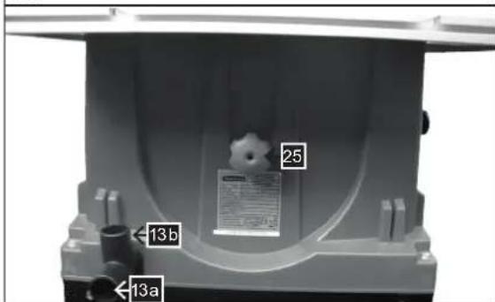
Fig. 1.4
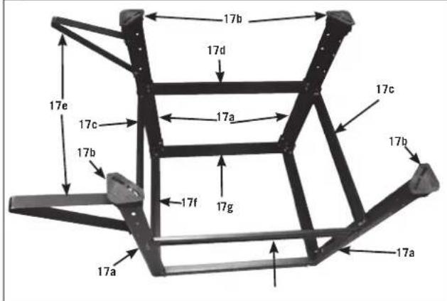
Fig. 1.1
2

2.1
natural_image
Black metal frame with a 17cm measurement annotation (no other text or symbols)2.2
2.7

natural_image
Close-up of a metal rod with a curved arm and mounting bracket, labeled '17 e' (no other text or symbols)2.3
2.8

natural_image
Black metal frame structure with no visible text or symbols2.4

natural_image
Metal frame structure with support beams and mounting holes (no text or symbols visible)2.9
natural_image
Close-up of a black metal bracket with mounting holes and a hook (no text or symbols visible)2.5
2.10
2.6
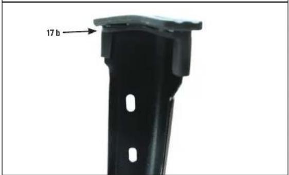
Fig. 3

natural_image
Close-up of a black plastic object on a white wooden panel, with no visible text or symbols.Fig. 3.1
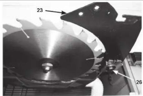
Fig. 4
5
5.1

natural_image
Industrial conveyor belt system with metal components and control lever (no visible text or symbols)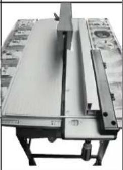
natural_image
Close-up of a mechanical device with metallic components and a rolled sheet of paper on top (no visible text or symbols)6
natural_image
Close-up of a mechanical device with a hand operating a flat surface, showing gears and a central knob (no visible text or symbols)7
8

natural_image
Technical line drawing of a mechanical assembly with hands operating a workpiece (no text or symbols)9
natural_image
Line drawing of a hand using a tool to cut or cut a piece of wood on a wooden table (no text or symbols)10
natural_image
Technical line drawing of a mechanical assembly with hands operating a workpiece (no text or symbols)11
natural_image
Technical line drawing of a mechanical setup with a hand operating a workbench and a tool, no text or symbols present.Fig. 12.1
natural_image
Close-up of gloved hands using a tool to cut a mechanical component with teeth and gears (no visible text or symbols)Fig. 12.2

natural_image
Close-up of a mechanical component with a metallic blade and serrated edge (no visible text or symbols)
natural_image
Two mechanical components: a black washer and a hexagonal nut, placed on a lined surface (no text or symbols visible)HERSTELLER:
scheppach
Günzburger Straße 69
D-89335 Ichenhausen
VEREHRTER KUNDE,
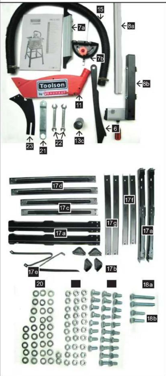
22 Gabelschlüssel 10/13
23 Spaltkeil
Günzburger Straße 69
D-89335 Ichenhausen
DEAR CUSTOMER,
we wish you a pleasant and successful working experience with your new TOOLSON machine.
Advice: according to the applicable product liability law the manufacturer of this device is not liable for damages which arise on or in connection with this device in case of:
- improper handling,
• non-compliance with the instructions for use,
• repairs by third party, non authorized skilled workers, - installation and replacement of non-original spare parts,
- improper use,
- failures of the electrical system due to the non-compliance with the electrical specifications and the VDE 0100, DIN 57113 / VDE 0113 regulations
WE RECOMMEND
that you read through the entire operating instructions before putting into operation.
These operating instructions are to assist you in getting to know your machine and utilize its proper applications. The operating instructions contain important notes on how you work with the machine safely, expertly, and economically, and how you can avoid hazards, save repair costs, reduce downtime and increase the reliability and service life of the machine.
In addition to the safety requirements contained in these operating instructions, you must be careful to observe your country's applicable regulations.
The operating instructions must always be near the machine. Put them in a plastic folder to protect them from dirt and humidity. They must be read by every operator before beginning work and observed conscientiously. Only persons who have been trained in the use of the machine and have been informed of the various dangers may work with the machine. The required minimum age must be observed.
In addition to the safety requirements contained in these operating instructions and your country's applicable regulations, you should observe the generally recognized technical rules concerning the operation of woodworking machines.
GENERAL NOTES
- After unpacking, check all parts for any transport damage. Inform the supplier immediately of any faults.
- Later complaints cannot be considered.
• Make sure the delivery is complete. - Before putting into operation, familiarize yourself with the machine by carefully reading these instructions.
- Use only original TOOLSON accessories, wearing or replacement parts. You can find replacement parts at your TOOLSON dealer.
- When ordering, include our item number and the type and year of construction of the machine.
| PRO TS 3000 | |
| Delivery status | |
| Circular Saw Bench PRO TS 3000 | |
| Longitudinal stop | |
| Cross-cutting gauge | |
| Saw blade cover with screw and toggle screw | |
| Splitting wedge | |
| Shift rod | |
| 2 supports | |
| Extraction hose with 2 hose clamps | |
| 2 x Saw blade keys SW 10/13 | |
| 1 x Saw blade key SW 10/24 | |
| Accessories kit | |
| Manual | |
| Technical data | |
| Dimensions L x W x H | 900 x 570 x 1100 mm |
| Size of bench | 625 x 530 mm |
| Height of bench with base frame | 900 mm |
| ø Saw blade | 250 x 30 x 2,4/1,6 24 Z |
| Height adjustment 90° | 80 mm |
| Displacement | 90°-45° |
| Cutting speed m/sec | 75 |
| Longitudinal stop | 470 mm |
| Cutting width l/r | 180/205 mm |
| Weight | 21 kg |
| Drive | |
| Motor V/Hz | 230-240/50 Hz |
| Performance input P1 | 1800 W |
| Operation mode | S6 40% |
| Number of revolutions | 5700 min-1 |
| Motor protection | IP20 |
| Undervoltage cutback | yes |
| Connector | Schuko |
| Subject to technical changes! | |
NOISE CHARACTERISTIC VALUES
Measurement conditions
The values stated are emission values and are therefore not necessarily safe operating values. Although there is a correlation between emission and immission levels, you cannot reliably deduce from this whether additional safety measures are required or not. Factors which can influence the immission level currently at the workstation comprise the duration of the effects, the characteristics of the work room, other sources of noise etc., for example, the number of machines and adjacent operations. The permissible values per workstation can also vary from country to country. This information should nevertheless enable the user to make a better estimation of dangers and risks.
Sound level in dB
Operation L_WA = 112,4 dB(A)
Sound level at the workplace in dB
Operation L_pAeq = 102.5 dB(A)
A measurement uncertainty allowance K = 3 dB applies to the mentioned emission values.
Test performed according to EN 61029-2-1:2010.
INFORMATION ON DUST EMISSION
The dust emission values measured in accordance with the „principles for testing dust emission“ of the committee of experts of wood are below 2 mg/m3. This means that the TRK limit for wood dust which is valid in the Federal Republic of Germany will be permanently kept to if the machine is connected to a properly working dust extractor with at least 20 m/s air speed.
 | Use hearing or ear protection. |
 | Use protective mask and goggles. |
 | Use eye protection. |
 | Read the manual before working with this machine |
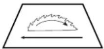 | Indication of cutting line and rotation direction of saw blade |
In these operating instructions we have marked the places that have to do with your safety with this sign: △
⚠️ Safety notes
- Please pass on safety notes and instructions to all those who work on the machine.
- The machine must only be used in technically perfect condition in accordance with its designated use and the instructions set out in the operating manual, and only by safety-conscious persons who are fully aware of the risks involved in operating the machine. Any functional disorders, especially those affecting the safety of the machine, should therefore be rectified immediately.
- Only tools which correspond to the European norm, EN 847-1, may be used.
- Observe all safety instructions and warnings attached to the machine.
- See to it that safety instructions and warnings attached to the machine are always complete and perfectly legible.
- Caution when working: There is a danger to fingers and hands from the rotating cutting tool.
-
Make sure that the machine stands stable on firm ground.
-
Check all power supply lines. Do not use defective lines.
- Keep children away from the machine when it is connected to the power supply.
- Operating personal must be at least 18 years of age. Trainees must be at least 16 years of age, but may only operate the machine under adult supervision.
- Persons working on the machine may not be diverted from their work.
- The machine must be equipped with a table length extension if a second person is working at the circular sawbench removing cut workpieces. The second person may not stand anywhere else but at the take-off table end.
- The working space on the machine must be free of chips and wood scrap.
- Wear only close-fitting clothes. Remove rings, bracelets and other jewelry.
- Pay attention to the rotational direction of the motor – see Electrical Connection.
- The safety mechanisms on the machine may not be removed or rendered unusable.
- Cleaning, changing, calibrating, and setting of the machine may only be carried out when the motor is switched off. Pull the power supply plug and wait for the rotating tool to completely stop.
- Switch the machine off and pull power supply plug when rectifying any malfunctions.
- The machine must be attached to a dust extractor during all work cycles. Please observe the proper use of this.
- When working on the machine, all safety mechanisms and covers must be mounted.
- Use only sharpened, nick-free and non-deformed saw blades.
- Circular saw blades made from superspeed steel may not be used.
- The splitting wedge is an important safety feature. The workpiece is fed through the splitting wedge, which prevents the cut from closing behind the saw blade and also prevents the workpiece from kicking back.
- Lower the cover onto the workpiece during every working operation. It must stand horizontal above the saw blade.
- Always use a push-stick for longitudinal cuts of narrow workpieces (less than 120 mm). The push-stick must be used to prevent you from having to work with your hands near the sawblade. Stop the machine to repair a failure or remove pieces of wood which have become jammed. Disconnect the mains plug.
- Switch the machine off and pull power supply plug when rectifying any malfunctions.
- The table insert must be renewed when the saw slot is worn down. Pull power supply plug.
- Before the machine is put into operation it must be connected to a dust extractor with a flexible, non-flammable suction hose. The suction should switch on automatically when the machine is switched on.
- When leaving the work place, switch the motor off.
Pull the power supply plug.
- Cut off the external power supply of the machine or plant even if only minor changes of place are envisaged. Properly reconnect the machine to the supply mains before recommissioning.
- Connection and repair work on the electrical installation may be carried out by a qualified electrician only.
- All protection and safety devices must be replaced after completing repair and maintenance procedures.
- Do not expose power tools to rain.
- Do not use power tools in a damp or wet surrounding.
- Make sure that there is sufficient illumination in the working place.
- Do not use power tools where there is a risk of fire or explosion.
- Avoid physical contact with parts that may cause electric shock (for example pipes, radiators, electric ranges, cooling unit).
- Power tools that are not in use should be stored in a dry, elevated or safely locked place, out of the reach of children.
- Do not pull the cable to unplug. Keep cable away from heat, oil and sharp objects.
- Use fastening devices or a bench vice to fasten the tools. It is safer than fastening by hand.
- Keep handles dry, clean and free of oil and fat.
- Make sure that the switch is on an off position when plugging into the power socket.
- Only use approved and specified extension cables for outdoors.
- Do not use power tools where the switch can not be switched on or off.
- Circular saws can not be used for slitting (in the work piece ended nut.)
- Only use saw-blades with a maximum speed that is not lower than maximum spindle speed of the circular saw bench for the material to be cut.
- Only use appliances that are suitable for transportation when moving the device. Never use the protection device for handling or transportation.
- The upper part of the saw blades should be covered before transportation, for example with protection gear.
- WARNING! When using electric tools basic safety precautions should always be followed to reduce the risk of fire, electric shock and personal injury including the following
- Use only saw blades recommended by the manufacturer, which conform to EN 847-1, with a warning that the riving knife shall not be thicker than the width of the groove cut by the saw blade and not thinner than the body of the saw blade.
- saw blades shall be carried in a holder whenever practicable. The push-stick or push block should always be stored with the machine when not in use. Rebating or grooving should not be carried out. Saws shall not be used for slotting(stopped groove)
⚠ Use only as authorized
The machine corresponds to the valid EC guideline.
- The circular sawbench is defined as a transportable machine.
- To transport the machine, grasp the table firmly at the front and at the rear using both hands and lift the machine.
- If an original base is not used, the machine must be placed firmly upon a stable stand resembling a table. The working height should be 850 mm.
- The machine's workstation is in front of the machine to the left of the saw blade.
- The machining range and surrounding areas of the machine must be clear of interfering foreign matter to prevent accidents occurring.
- Workpieces must be completely free of foreign objects, i.e. nails or screws.
- Before the machine is put into operation it must be connected to a dust extractor with a flexible, non-flammable suction hose. The suction should switch on automatically when the machine is switched on.
- When used in enclosed rooms, the machine must be connected to a vacuum exhaust unit. Use the dust extractor ha 3200 or ha 2600 to remove match wood or saw dust. The vacuum support flow rate must be 20 m/s. Subatmospheric pressure 1200 Pa.
- The automatic switching unit is available as a special accessory.
Type ALV 2 Art. No. 7910 4010 230–240 / 50 Hz
The vacuum exhaust unit automatically switched on after a 2-3 second delay after the machine tool is turned on. This avoids overloading the circuit fuse.
After turning off the machine tool, the vacuum exhaust unit remains on for an additional 2-3 seconds and is then automatically switched off. Remaining dust is thereby removed by vacuum exhaust, as required by German regulations governing hazardous materials. This results in savings in electricity consumption and reduces noise levels, as the vacuum exhaust unit is on only during machine tool operation.
- For work in commercial spaces, an appropriate dust extractor must be used. Do not remove or shut off vacuum exhaust systems or dust removers while machine tools are operating.
- The circular sawbench is designed exclusively for the machining of wood and materials similar to wood. Only original tools and accessories may be used. Use the required sawblade in accordance with the EN 847-1 norm depending on the type of cut and type of wood (solid wood, plywood or chipboard). Please observe the „Special Tool Accessories“.
- The machine must only be used in technically perfect condition in accordance with its designated use and the instructions set out in the operating manual, and only by safety-conscious persons who are fully aware of the risks involved in operating the machine. Any functional disorders, especially those affecting the
safety of the machine, should therefore be rectified immediately.
- Relevant accident prevention regulations and other, generally recognized safety-technical rules must also be adhered to.
- The machine may only be used, maintained, and operated by persons familiar with it and instructed in its operation and procedures. Arbitrary alterations to the machine release the manufacturer from all responsibility for any resulting damages.
- The machine may only be used with original accessories and original tools made by the manufacturer.
- Any other use exceeds authorization. The manufacturer is not responsible for any damages resulting from unauthorized use; risk is the sole responsibility of the operator.Remaining hazards.

Remaining hazards
The machine has been built using modern technology in accordance with recognized safety rules. Some remaining hazards, however, may still exist.
- The rotating saw blade can cause injuries to fingers and hands if the work piece is incorrectly fed.
- Thrown work pieces can lead to injury if the work piece is not properly secured or fed, such as working without a limit stop.
- Noise can be a health hazard. The permitted noise level is exceeded when working. Be sure to wear personal protective gear such as ear protection.
- Defective saw blades can cause injuries. Regularly inspect the structural integrity of saw blades.
- The use of incorrect or damaged mains cables can lead to injuries caused by electricity.
- The operating instructions supplied with the special accessories must be observed and carefully read when special accessories are used.
- Even when all safety measures are taken, some remaining hazards which are not yet evident may still be present.
- Remaining hazards can be minimized by following the instructions in "Safety Precautions", "Proper Use" and in the entire operating manual.
Setting up
Prepare the location where the machine is due to be mounted Make sure there is sufficient space to enable a safe failure free functioning The machine is designed for operation in enclosed areas and is to be set up on a stable level surface.
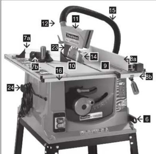
Equipment, Fig. 1
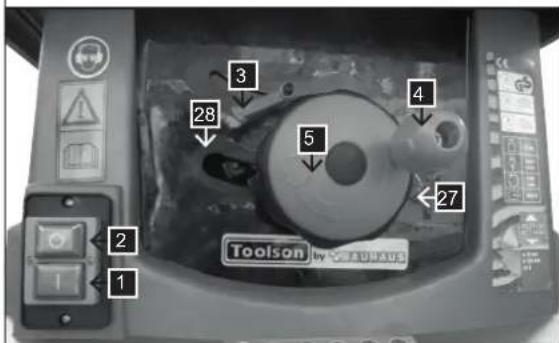
Controls and parts
1 Bench top
2 On/off switch
3 Cable storage
4 Length stop
5 Clamping lever for Fence
6 Crosscut gauge
7 Blade guard
8 Extractor
9 Height and angle adjustment wheel for saw blade
10 Lock lever for setting angle
11 Scale of saw blade angles
12 Push stick
13 Sub-frame
14 Outriggers
15 Blade
16 Gap wedge
17 Table insert
Assembly and Installation
All assembly and retrofitting work may only be performed when the mains plug has been disconnected.
Your circular sawbench is not completely assembled for packaging reasons.
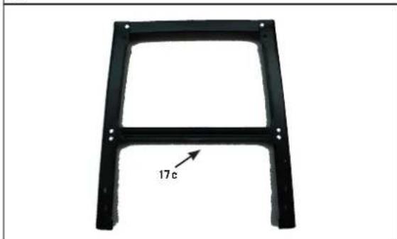
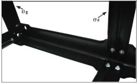
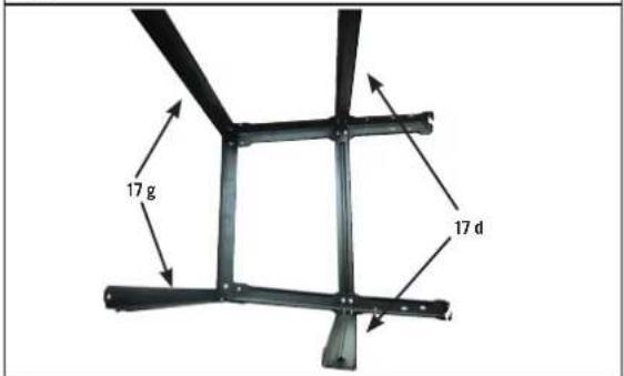
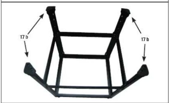
Mounting Sub-frame PRO TS 3000 Fig.2
Mounting parts:
4 Support angles (2 x short and 2 x long)
4 Frame feet
4 Frame struts (2 x short and 2 x long)
4 Base plate
2 Outrigger fasteners
When assembling tighten all the mounting screws lightly by hand
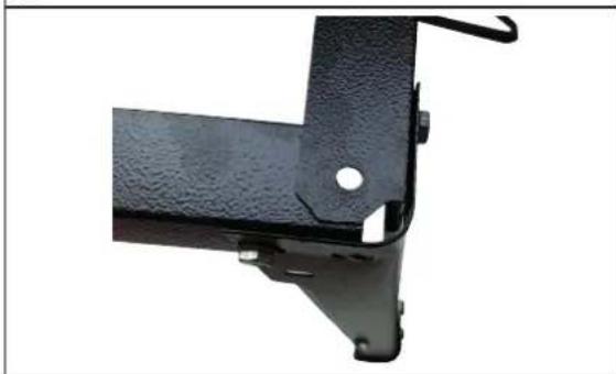
- Attach the 4 support angles (a) to the base (b) with 2 hex screws, 2 washers and 2 hex nuts each
- Attach the 4 frame struts (c) to the base (b) with 4 hex screws, 4 washers and 4 nuts each.
- Attach the 2 base feet (e) to the base with 2 screws, 2 washers and 2 nuts each.
- Attach the 4 feet (d) to the base (b).
- Place the frame on a flat surface.
- Tighten all the screws.
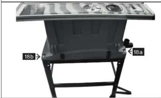
- Set the machine on the base so that the supporting feet (e) are at the back of the saw. Screw it together firmly with the 4 hex screws, 4 washers and 4 hex nuts
Fig. 3 Assembling the splitting wedge
- Remove the table insert (Fig. 3.1)
- Set the blade to the highest position
- Loosen the screw (a) of the reamer clamp (b), place the reamer (16) between the metal plate and the plastic terminal block.
- Adjust the height of the wedge so that the gap between the reamer and saw teeth along the curve of the blade is exactly the same, and no more than 5mm.
- Tighten the screw to the reamer to hold it in this position
- Replace the table insert (17).
Installing and removing the saw blade protection, Fig. 4
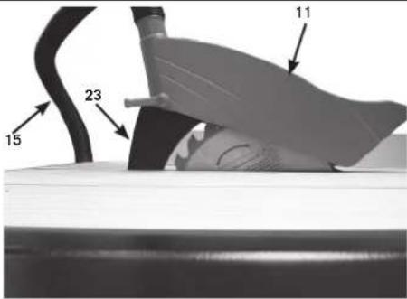
- To remove the protective guard (7), loosen the toggle screw (a) and pull the guard forwards.
- To replace the protective guard (7) place the guard over the reamer (16), so that the toggle screw (a) fits into the reamer slot.
- Then push the guard back, so that the toggle screw fits into the foot of the slot.
- Fasten the nut tightly. The protection device has to rest on the bench top (1), but has to elevate when the work piece is pushed against the saw blade. Note: After sawing the work piece, the saw blade protection has to return to its resting position.
- Connect the hose (8) between the output on the protection device (7) and one of the extraction nozzles. A safety clamp is included. The second nozzle can be connected to a suitable extraction system or a common vacuum cleaner.
Caution: The saw blade protection (7) has to be in operation position at all times, in order to avoid contact with the saw blade. It should move itself onto the work piece during sawing.
Fig. 1 Storing the push stick.
- To store the push stick (12) there is a holder to the right of the saw.
- Caution: Replace the stick into its holder after every time it is used.
Putting into Operation
Observe the safety instructions!
Important: The machine must only be brought into service with completely installed safety and protection devices. Before starting to use it, connect the machine to an extraction system.
For every operation, the extraction cover has to be lowered down to the work piece.
The settings of the machine have to ensure that the top of the highest saw tooth is positioned just a little higher than the work piece.
Before switching on the machine, all safety and protection devices have to be installed according to the instructions.
The saw blade must move freely.
Always check timber, which has been processed before, for foreign objects (nails, screws, etc.). Remove all foreign matter.
Before turning on the power supply, make sure that the saw blade is installed correctly and that the moving components can move freely.
Warning: If in doubt, have the machine set by a qualified person. It is too dangerous to work on assumptions.
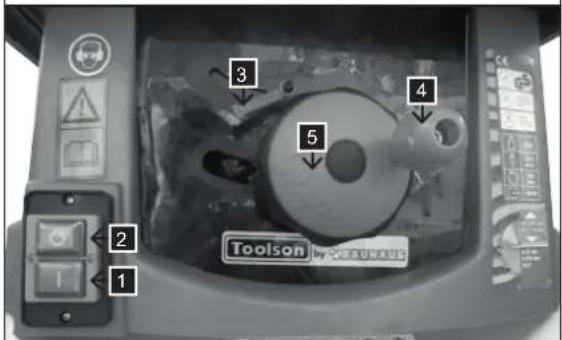
Turning the machine on and off, Illustration 1 (2)
- Press the green push button to turn the machine on.
- Press the red push button to turn the machine off.
Adjusting the cutting height, Illustration 1 (10)
Warning: The saw blade lock has to be secured (10).
- Set the required cutting height by turning the height adjustment wheel (9).
- Turning it anti-clockwise will increase the cutting
height.
- Turning it clockwise will decrease the cutting height.
Using the longitudinal stop
Cutting width, Illustration 1
- Use the longitudinal stop for longitudinal cuts.
- The longitudinal stop (4) can be installed on either side of the bench top (1).
- In order to use the scale, move the stop to the saw blade and measure using the scale. Now move the stop away from the saw blade. The measuring difference is identical to the cutting width. In order to achieve an exact measurement, it is necessary to carry out a test cut, to measure the work piece and to readjust the stop.
- Lift the locking lever (5) and move the stop to the required position.
- Secure the locking lever (5).
Warning: The longitudinal stop always has to be adjusted in parallel to the saw blade. Check this, as well as the tension of the fastening components regularly and whenever the saw has not been used for several days.
Usage of the cross-cutting jig, Illustration 1
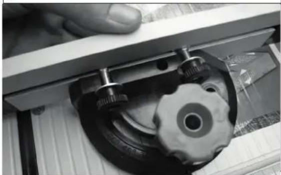
- Push the cross-cutting jig (6) into the groove of the bench top (1).
- Release the button on the cross-cutting jig.
- Turn the cross-cutting jig, in order to achieve the required angle.
- Refasten the button.
- In order to set the stop from one side of the quadrant to the other, release both synthetic nuts that hold the stop, remove the stop, place it on the other side and secure the synthetic nuts.
Adjusting the angle of the saw blade, Illustration 1
- Release the saw blade lock (10) and turn the hand wheel (9) until the indicator is points at the correct angle on the scale (11).
- The angle indicator can be adjusted while checking the exactness of the angle of the saw blade. Set an angle against the saw blade when the machine is turned off and the power supply is disconnected. Adjust the hand wheel until the saw blade is parallel to the angle. Then set the indicator of the scale to 0^ .
- Lock after setting.
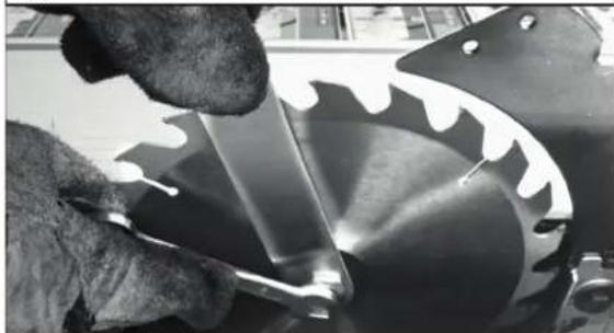
Fig. 3.1, 3.2, 3.3, Changing the saw blades
Warning: Turn off the machine and disconnect from the power supply, before conducting any settings or maintenance work or before replacing the saw blade.
Wear gloves when handling saw blades.
- Turn the blade to its highest position.
- Remove the blade guard (7) Fig .4
- Remove the table insert (17) Fig. 3.1
- Hold the spindle firmly with a 10 mm open-end spanner. With a 24 mm open-end spanner loosen the blade fixing screw by turning it clockwise (right-handed) (Fig. 3.2).
-
Remove the nut and the outer flange and lift off the saw blade. (Fig. 3.3)
-
Thoroughly clean both anges before you install another saw blade.
- Install and secure the saw blade following the instructions in reverse.
Caution: Observe the running direction of the saw blade. The cutting edge of the teeth has to point into the running direction, meaning forwards (see arrow on saw blade). - Reinstall the splitting wedge and adjust it. Reinstall the saw blade protection.
- Before using the saw, make sure that all safety devices are working correctly. Important: After assembly, check if the saw blade is running freely by turning it manually.
- Connect the saw to the power supply and let it idle, before starting to saw.
Operational Information
Working on circular saws
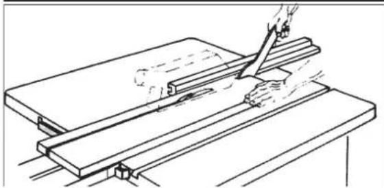
Cutting wide workpieces, Fig. 19
Width of the workpiece to be machined over 120 mm
Tool: Circular sawblade for longitudinal cuts
Operating cycle: Adjust the ripping fence in accordance with the width of the workpiece. Ensure that your hands are resting in a safe place. The workpiece may only be forward-fed in the tool area with the right hand or with the aid of a push-stick if narrow workpieces are cut off in the cutting process. Move the fence back to the middle of the saw or use a short auxiliary fence if there is a danger of the workpiece being jammed between the circular sawblade, the riving knife and the fence.
Only the upper suction hood has been indicated in the gures on pages 26-28 or has been left out in the individual case in order to display the operating cycle or device more clearly.
The upper suction hood is required for all of the operating cycles.
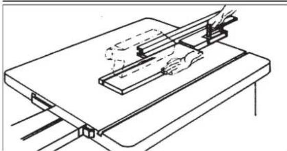
Cutting narrow workpieces, Fig. 20
Width of the workpiece to be machined less than 120 mm
Tool: Circular sawblade for longitudinal cuts
Operating cycle: Adjust the fence in accordance with the width of the workpiece. Feed the workpiece with both hands (use the push-stick in the region of the sawblade) and push the workpiece until it is behind the riv-ing knife. Use the push-stick to feed the workpiece right from the beginning of the cutting process if short workpieces are being used.
Cutting edges and strips, Fig. 21
Tool: Circular sawblade for a ne cut
Operating cycle: Mount the fence with a low stop bar surface or use an auxiliary fence. Feed the workpiece with a push-stick until the end of the workpiece is in the region of the riving knife. Prevent long workpieces from toppling over at the end of the cutting process by using a table length extension.
Note: Devices which must be connected to parts of the machine are to be secured with screws. Thumb screws can only be used to make temporary connections at machines.
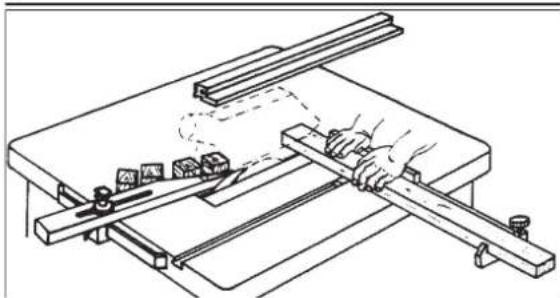
Cross-cutting narrow workpieces, Fig. 22
Tool: Fine-toothed crosscut blade
Operating cycle: Adjust the rejection rail so that workpiece sections do not touch the ascending part of the sawblade. Only feed the workpiece by means of a crossfeed stop or a cross slide.
Do not remove wood chippings from the region of the workpiece with your hands.
Electrical Connection
The electric motor is connected in a ready-to-operate state. The connection corresponds to the relevant VDE and DIN regulations.
The mains connection at the customer's work place and the extension cable used must correspond to these regulations.
Important information
The 230-240 V / 50 Hz electric motor is designed for the S6 / 40% operating mode.
Faulty electrical connecting leads
Insulation damage often occurs at electrical connecting leads.
Causes include:
- Pressure marks caused when connecting leads are run through windows or the cracks of doors.
- Folds caused by the improper attachment of running of the connecting leads.
- Cutsresulting from the crossing of the connecting lead.
• Insulation damages caused by the ripping out of the connecting lead from the wall socket.
• Cracks due to the ageing of the insulation.
Faulty electrical connecting leads such as these may not be used and are highly dangerous due to the insulation damage.
Check electrical connecting leads regularly for damage. Ensure that the connecting lead is not attached to the mains supply when you are checking it.
Electrical connecting leads must correspond to the relevant VDE and DIN regulations. The type designation must be printed on the connecting lead by regulation.
Single-phase motor
- The supply voltage must be 230-240 volt – 50 Hz.
- Extension leads up to 25 m in length must have a cross-section of 1.5 mm ^2 . Extension leads whose length is over 25 m must have a cross-section of at least 2.5 mm ^2 .
- The mains connection is fused with a A 16A slow-blow fuse.
Connections or repairs on the electrical equipment may only be carried out by an electrician.
Please give the following information if you have any enquiries.
- Motor manufacturer
- Kind of current
• Machine type label data
If your are sending back the motor, always send the complete drive unit with the switch.
Maintenance
Warning: Turn off the machine and disconnect from the power supply before conducting maintenance work or settings.
Store the manual close to the machine.
Keep the machine clean.
Wear goggles when cleaning the machine.
Caution: Do not clean synthetic components of the bench using aggressive cleaning agents. We recommend a mild dish washing liquid. The machine must not get into contact with water.
- Check the saw blade regularly. Use only well-sharpened, crack-free and not distorted saws. Use only tools that comply with the European standard EN 847-1.
- Exchange immediately table lining that run out.
• Always keep table surface nonresinous. - Clean regularly the inner section of the machine, like tooth segment and pinion of the oscillating device, of wood and chip rests.
- Remove possible sawdust blockages at the discharge.
Accessories
-driver device (Art.No. 3901301702)
-table extension (Art.No. 3901301701)
Troubleshooting table
Warning: In the interests of operational safety, always switch off the saw and remove the mains plug before carrying out maintenance work.
| Problem Possible Cause Help | ||
| Saw blade gets loose after turning off the motor | Fastening nut tightened insufficiently Tighten fastening | M20 left-handed thread |
| Motor does not start a) F | Fastening nut tightened insufficientlyb) Extension cable defectc) Connections on the motor or switch defect | a) Check the mains fuse.b) See “Electrical Connection” in the operating manualc) Have it checked by an electrician |
| No motor output turns off automatically | Overload by dull saw blade, thermoprotection is triggered | Insert a sharpened saw blade; motor can be turned on again after the cooling period |
| Burns on the cutting surfacec) with longitudinal cutsd) with cross cuts | a) Fastening nut tightened insufficientlyb) Wrong saw bladec) Longitudinal stop not paralleld) Slide carriage not parallel | a) Insert a sharpened saw bladeb) Insert saw blade with 20 or 28 teeth for longitudinal cutsc) Exchange the longitudinal stopAlign the slide carriage with the saw blade |
CONSTRUCTEUR:
scheppach
Günzburger Straße 69,
D-89335 Ichenhausen
CHER CLIENT,
Günzburger Straße 69
D-89335 Ichenhausen
GENTILE CLIENTE,
Günzburger Straße 69
D-89335 Ichenhausen
ARADE KUND!
Günzburger Straße 69
D-89335 Ichenhausen
HYVÄ ASIAKAS,
Günzburger Straße 69
D-89335 Ichenhausen
KJRERE KUNDE,
Günzburger Straße 69
D-89335 Ichenhausen
AEREDE KUNDE,
Günzburger Straße 69
D-89335 Ichenhausen
Vážený zákazník,
Günzburger Straße 69
D-89335 Ichenhausen
Sayın Müşterimiz,
Günzburger Straße 69
D-89335 Ichenhausen
KÆRI VIDSKIPTAVINUR,
Günzburger Straße 69
Günzburger Straße 69
D-89335 Ichenhausen
GERBIAMASIS KLIENTE,
Günzburger Straße 69
D-89335 Ichenhausen
POŠTOVANI KORISNIČE,
Günzburger Straße 69
D-89335 Ichenhausen
■ SPOŠTOVANI KUPEC,
Günzburger Straße 69
D-89335 Ichenhausen
GEACHTE KLANT,
Günzburger Straße 69
D-89335 Ichenhausen
VÁŽENÝ ZÁKAZNÍK!
KROK 2. ROZOVIERACÍ KLIN, OBR. 3–3.1
1 Rozovierací klin
Günzburger Straße 69
D-89335 Ichenhausen
CIJENJENI KUPČE,
Želimo Vam mnogo radosti i uspjeha u radu s Vašom novom mašinom TOOLSON.
NAPOMENA:
Proizvođač ovog uređaja u skladu s važećim zakonom o odgovornosti za poizvode ne preuzima nikakvu odgovornost za štete koje nastanu na ovom uređaju ili zbog ovog uređaja uslijed:
- nepropisnog rukovanja,
- nepoštovanja uputstava za rukovanje,
- popravki od strane trećih lica koja nisu ovlaštena stručna lica,
- ugradnje i zamjene neoriginalnih rezervnih dijelova,
- nenamjenske upotrebe,
- ispada električnog sistema zbog nepoštovanja električnih propisa i VDE odredbi 0100, DIN 57113 / VDE 0113.
MI VAM PREPORUČUJEMO:
Prije montaže i puštanja u rad pročitajte cjelokupni tekst uputstva za rukovanje.
Ovo uputstvo za rukovanje treba da Vam olakša upoznavanje Vaše mašine i korištenje njenih namjenskih mogućnosti upotrebe.
U uputstvu za rukovanje nalaze se važne napome- ne o tome kako da koristite mašinu sigurno, propisno i ekonomično i kako da izbjegavate opasnosti, uštedite na troškovima popravki, smanjite vremena ispada i povećate pouzdanost i životni vijek mašine. Dodatno uz sigurnosne odredbe ovog uputstva za rukovanje ob-avezno morate poštovati propise Vaše zemlje koji se odnose na rad ovakve mašine. Sačuvajte uputstvo za rukovanje u blizini mašine, zaštićeno u od prljavštine i vlažnosti u plastičnoj vrećici. Njega prije početka rada mora pročitati i u potpunosti slijediti svaka osoba koja rukuje mašinom. Na mašini smiju raditi osobe kojima je objašnjena upotreba mašine i koje su dobile instrukci- je o opasnostima koje su povezane s radom na mašini. Potrebno je pridržavati se pravila o minimalnoj starosnoj dobi rukovalaca.
Pored sigurnosnih napomena koje su sadržane u ovom uputstvu za rukovanje i posebnih propisa koji važe u Vašoj zemlji, pri radu s mašinama za obradu drveta moraju se poštovati i općepriznata tehnička pravila.
OPĆE NAPOMENE
1. KORAK POSTOLJE, SL. 2-2.10
Günzburger Straße 69
D-89335 Ichenhausen
УВАЖАЕМИ КЛИЕНТИ,
Günzburger Straße 69
D-89335 Ichenhausen
| 2009/105/EC | 89/686/EC_96/58/EC | |
| X 2006/95/EC | X 2006/42/EC | |
| 2006/28/EC | X | Annex IVNotified Body: TÜV Rheinland LGA Products GmbHNotified Body No.: 0197Reg. No.: |
| 2005/32/EC | ||
| X 2004/108/EC | 2000/14/EC_2005/88/EC | |
| 2004/22/EC | Annex V | |
| 1999/5/EC | Annex VINoise: measured L_WA =xx dB(A); guaranteed L_WA =xx dB(A)Notified Body: | |
| 97/23/EC | 2004/26/EC | |
| 90/396/EC | Emission. No: | |
| X 2011/65/EU | ||
Standard references: EN 61029-1, EN 61029-2-1
| DE | |
 | Werfen Sie Elektrowerkzeuge nicht in den Hausmüll!Gemäß europäischer Richtlinie 2002/96/EG über Elektro- und Elektronik-Altgeräte und Umsetzung in nationales Recht müssen verbrauchte Elektrowerkzeuge getrennt gesammelt und einer umweltgerechten Wiederverwertung zugeführt werden. |
| GB | |
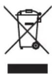 | Do not dispose of electric tools together with household waste material!In observance of european directive 2002/96/EC on wasted electrical and electronic equipment and its implementation in accordance with national law, electric tools that have reached the end of their life must be collected separately and returned to an environmentally compatible recycling facility. |
| FR | |
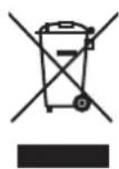 | Ne pas jeter les appareils électriques dans les ordures ménagères!Conformément à la directive européenne 2002/96/EG relative aux déchets d'équipements électriques ou électroniques (DEEE), et à sa transposition dans la législation nationale, les appareils électriques doivent être collectés à part et être soumis à une recyclage respectueux de l'environnement. |
| IT | |
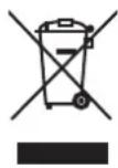 | Non gettare le apparecchiature elettriche tra i rifiuti domestici!Secondo la Direttiva Europea 2002/96/CE sui rifiuti di apparrecchiature elettriche ed elettroniche e la sua attuazione in conformità alle norme nazionali, le apparecchiature elettriche esauste devono essere raccolte separatamente, al fine di essere reimpiegate in modo eco-compatibile. |
| NL | |
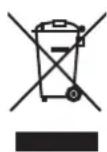 | Geef elektrisch gereedschap niet met het huisvuil mee!Volgens de europese richtlijn 2002/96/EG inzake oude elektrische en elektronische apparaten en de toepassing daarvan binnen de nationale wetgeving, dient gebruikt elektrisch gereedschap gescheiden te worden ingezameld en te worden afgevoerd naar en recycle bedrijf dat voldoet aan de geldende milieu-eisen. |
| ES | |
 | ¡No deseche los aparatos eléctricos junto con los residuos domésticos!De conformidad con la Directiva Europea 2002/96/CE sobre residuos de aparatos eléctricos y electrónicos y su aplicación de acuerdo con la legislación nacional, las herramientas electricas cuya vida útil haya llegado a su fin se deberán recoger por separado y trasladar a una planta de reciclaje que cumpla con las exigencias ecológicas. |
Apparent defects must be notified within 8 days from the receipt of the goods. Otherwise, the buyeris rights of claim due to such defects are invalidated. We guarantee for our machines in case of proper treatment for the time of the statutory warranty period from delivery in such a way that we replace any machine part free of charge which provably becomes unusable due to faulty material or defects of fabrication within such period of time. With respect to parts not
manufactured by us we only warrant insofar as we are entitled to warranty claims against the upstream suppliers. The costs for the installation of the new parts shall be borne by the buyer. The cancellation of sale or the reduction of purchase price as well as any other claims for damages shall be excluded.
Garantie FR
- HERSTELLER:
- VEREHRTER KUNDE,
- DEAR CUSTOMER,
- WE RECOMMEND
- GENERAL NOTES
- NOISE CHARACTERISTIC VALUES
- Measurement conditions
- Sound level in dB
- Sound level at the workplace in dB
- INFORMATION ON DUST EMISSION
- ⚠️ Safety notes
- ⚠ Use only as authorized
- The machine corresponds to the valid EC guideline.
- Remaining hazards
- Setting up
- Equipment, Fig. 1
- Controls and parts
- Assembly and Installation
- Mounting Sub-frame PRO TS 3000 Fig.2
- Fig. 3 Assembling the splitting wedge
- Installing and removing the saw blade protection, Fig. 4
- Fig. 1 Storing the push stick.
- Putting into Operation
- Observe the safety instructions!
- Turning the machine on and off, Illustration 1 (2)
- Adjusting the cutting height, Illustration 1 (10)
- Using the longitudinal stop
- Cutting width, Illustration 1
- Usage of the cross-cutting jig, Illustration 1
- Adjusting the angle of the saw blade, Illustration 1
- Fig. 3.1, 3.2, 3.3, Changing the saw blades
- Operational Information
- Working on circular saws
- Cutting wide workpieces, Fig. 19
- Cutting narrow workpieces, Fig. 20
- Cutting edges and strips, Fig. 21
- Cross-cutting narrow workpieces, Fig. 22
- Electrical Connection
- Important information
- Faulty electrical connecting leads
- Single-phase motor
- Connections or repairs on the electrical equipment may only be carried out by an electrician.
- Maintenance
- Accessories
- Troubleshooting table
- CONSTRUCTEUR:
- CHER CLIENT,
- GENTILE CLIENTE,
- ARADE KUND!
- HYVÄ ASIAKAS,
- KJRERE KUNDE,
- AEREDE KUNDE,
- Vážený zákazník,
- Sayın Müşterimiz,
- KÆRI VIDSKIPTAVINUR,
- GERBIAMASIS KLIENTE,
- POŠTOVANI KORISNIČE,
- ■ SPOŠTOVANI KUPEC,
- GEACHTE KLANT,
- VÁŽENÝ ZÁKAZNÍK!
- CIJENJENI KUPČE,
- NAPOMENA:
- MI VAM PREPORUČUJEMO:
- OPĆE NAPOMENE
- KORAK POSTOLJE, SL. 2-2.10
- УВАЖАЕМИ КЛИЕНТИ,
- Garantie FR
Brand : Toolson
Model : PRO TS 3000
Category : Saw