KGZ3400 - Saw Toolson - Free user manual and instructions
Find the device manual for free KGZ3400 Toolson in PDF.


| Product Type | Radial Miter Saw |
| Brand | Toolson |
| Model | KGZ3400 |
| Blade Diameter | 210 mm |
| Arbor | 30 mm |
| Dimensions (L x W x H) | 810 x 460 x 355 mm |
| Weight | 13.5 kg |
| Supply Voltage | 230 V / 50 Hz |
| Power Input | 1500 W (S6 25%) |
| No Load Speed | 5000 rpm |
| Rotation Angle (Miter) | -45° / 0° / 45° |
| Tilt Angle (Bevel) | 0° - 45° |
| Crosscut Capacity 90° | 58 x 340 mm |
| Miter Cut Capacity 45° | 58 x 240 mm |
| Bevel Cut Capacity 45° | 32 x 340 mm |
| Combined Cut Capacity 45° | 32 x 240 mm |
| Blade Type | Carbide Tipped Blade |
| Protection Class | II |
| Sound Pressure Level | 99.6 dB(A) |
| Sound Power Level | 112.6 dB(A) |
| Vibration | 4.51 m/s² |
| Laser | Class 2 |
| Included Accessories | Dust bag, socket wrench |
| Warranty | Legal warranty (defective parts) |
Frequently Asked Questions - KGZ3400 Toolson
User questions about KGZ3400 Toolson
0 question about this device. Answer the ones you know or ask your own.
Ask a new question about this device
Download the instructions for your Saw in PDF format for free! Find your manual KGZ3400 - Toolson and take your electronic device back in hand. On this page are published all the documents necessary for the use of your device. KGZ3400 by Toolson.
USER MANUAL KGZ3400 Toolson
natural_image
Toolson cutaw machine with black and white blades, no visible text or symbols on the device itselfKGZ3400
| DE | Kapp-ZugsägeOriginal-Anleitung | 4-11 |
| GB | Slide compund Mitre SawTranslation from the original instruction manual | 12-19 |
| FR | Scie à onglets radialesTraduction du manuel d'origine | 20-27 |
| IT | Sega troncatrice e a trazioneTraduzione dalle istruzioni d'uso originali | 28-35 |
| ES | Sierra pendular con cubiertaTraducción de la instrucción de original | 36-43 |
| TR | Gönye ve kırpma makinasıOrjinal operasyon el kitabindan çevirilmiştir | 44-51 |
| HR | Pila za rezanje pod kutom i podrezivanjePrijevod iz originalne upute za upotrebu | 52-59 |
| HU | Sarkaló és szegélyező fűrészForditás az eredeti használati utasitásból | 60-67 |
| FI | Katkaisu- ja vetosahaKäännös alkuperäisestä käyttööhjeesta | 68-74 |
| NO | Kapp- og gjerdesagOversettelse fra original brukermanual | 75-81 |
| DK | Kappe- og GeringssaveOversættelse fra den originale brugervejledning | 82-88 |
| SE | Kap- och stocksågÖversättning av original-bruksanvisning | 89-95 |
| CZ | Pokosová pilaPřeklad z originálního návodu | 96-102 |
| EE | Miiu- ja trimmimise saagTõlge originaall manuaal | 103-109 |
| RS | Нагибна тестераПревод са оригиналних кориснике | 110-117 |
| IS | GeirskurðarsögPýðing frá upprunalegri handbók | 118-125 |
| SI | Krožna žagaPrevod iz originalnega priročnika | 126-132 |
| SK | Kotúčová pokosová pílaPreklad originálneho návodu | 133-140 |
| BA | Pila za prorezivanje i koso rezanjePrijevod originalnog uputstva za upotrebu | 141-148 |
| BG | Циркулярен трион с герунгПревод на оригиналното ръководство | 149-157 |
| RU | Торцовочно-усорезная пилаПеревод оригиналного руководства | 158-166 |
| NL | Verstek- afkortzaagVertaling van de oorspronkelijke handleiding | 167-175 |
DE

Nur für EU-Länder.
Only for EU countries.
Do not dispose of electric tools together with household waste material! In observance of European directive 2012/19/EU on wasted electrical and electronic equipment and its implementation in accordance with national law, electric tools that have reached the end of their life must be collected separately and returned to an environmentally compatible recycling facility.
FR

natural_image
Close-up of a mechanical device with labeled component A, no readable text or symbols presentGünzburger Straße 69
D-89335 Ichenhausen
Verehrter Kunde,
Explanation of the symbols on the equipment
 | GB | Warning! Danger to life, risk of injury or damage to the tool are possible by ignoring!. |
 | GB | Caution - Read the operating instructions to reduce the risk of inquiry |
 | GB | Wear safety goggles! |
 | GB | Wear ear-muffs! |
 | GB | Wear a breathing mask! |
 | GB | Protection class II |
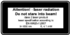
 | GB | Important! Laser radiation |
 |
Manufacturer:
Scheppach
Günzburger Straße 69
D-89335 Ichenhausen
Dear customer,
we wish you a pleasant and successful working experience with your new TOOLSON machine.
Advice:
According to the applicable product liability law the manufacturer of this device is not liable for damages which arise on or in connection with this device in case of:
- improper handling,
• non-compliance with the instructions for use,
• repairs by third party, non authorized skilled workers, - installation and replacement of non-original spare parts,
- improper use,
- failures of the electrical system due to the non-compliance with the electrical specifications and the VDE 0100, DIN 57113 / VDE 0113 regulations
Recommendations:
Read the entire text of the operating instructions prior to the assembly and operation of the device.
These operating instructions are intended to make it easier for you to get familiar with your device and utilize its intended possibilities of use.
The operating instructions contain important notes on how to work safely, properly and economically with your machine and how to avoid dangers, save repair costs, reduce downtime, and increase the reliability and working life of the machine.
In addition to the safety regulations contained herein, you must in any case comply with the applicable regulations of your country with respect to the operation of the machine.
Put the operating instructions in a clear plastic folder to protect them from dirt and humidity, and store them near the machine. The instructions must be read and carefully observed by each operator prior to starting the work. Only persons who have been trained in the use of the machine and have been informed on the related dangers and risks are allowed to use the machine. The required minimum age must be met.
In addition to the safety notes contained in the present operating instructions and the special regulations of your country, the generally recognized technical rules for the operation of wood working machines must be observed.
Know your Pullover Mitre Saw (Fig. 1)
1 Pullover carriage
2 Upper blade guard
3 Lower blade guard lock lever
4 Trigger switch
5 Handle
6 Motor
7 Lower blade guard
8 Tungsten Carbide Tipped blade
9 Fence
10 Extension support (optional)
11 Mitre scale
12 Arrester
13 Table insert
14 Turn table
15 Bolt holes
16 Base
17 Clamp
18 Dust bag
19 Handle
20 Laser
21 Table clamping handle
| Technical data | |
| ø blade 210 mm | |
| ø bore 30,0 mm | |
| Dimensions 810 x 460 x 355 mm | |
| Weight 13,5 kg | |
| ø turn table 250 mm | |
| Mitre stops left and right | 0°, 15°, 22,5°, 30°, 45° |
| Pivoting range | -45°/0°/45° |
| Inclination range | 0°–45° |
| Max. Capacity | |
| Cross cut at 90° | 58 x 340 mm |
| Mitre cut at 45° | 58 x 240 mm |
| Becel cut at 45° | 32 x 340 mm |
| Compound cut at 45° | 32 x 240 mm |
| Drive | |
| Motor V/Hz | 230V / 50 Hz |
| Consumption power P1 | 1500 W (S6 25%) |
| No load speed | 5000 1/min |
| Laser class | 2 |
Subject to technical changes!
The noise levels of this machine during cutting are as follows:
Noise level during working
$$ L _ {p A}: 9 9, 6 \mathrm{dB(A)} K = 3 \mathrm{dB(A)} $$
$$ L _ {w A}: 1 1 2, 6 \mathrm{dB(A)} K = 3 \mathrm{dB(A)} $$
Vibration:
$$ \text { Vibration: } 4, 5 1 \mathrm{m} / \mathrm{s} ^ {2} $$
$$ K = 1. 5 \mathrm{m} / \mathrm{s} ^ {2} $$
General Notes
- When you unpack the device, check all parts for possible transport damages. In case of complaints the supplier is to be informed immediately. Complaints received at a later date will not be acknowledged.
- Check the delivery for completeness.
- Read the operating instructions to make yourself familiar with the device prior to using it.
- Only use original TOOLSON parts for accessories as well as for wearing and spare parts. Spare parts are available from your specialized dealer.
- Specify our part numbers as well as the type and year of construction of the device in your orders.
In these operating instructions we have marked the places that have to do with your safety with this sign: △
General Safety Rules
WARNING! When using electric tools basic safety precautions should always be followed to reduce the risk of fire, electric shock and personal injury.
- Keep work area clear. Cluttered areas and benches invite injuries.
- Consider work area environment. Do not expose tools to rain. Do not use tools in damp or wet locations. Keep work area well lit. Do not use tools in the presence of flammable liquids or gases.
- Guard against electric shock. Avoid body contact with earthed or grounded surfaces.
- Keep other people away. Do not let others, especially children, get involved in the work touch the tool or the extension lead and keep them away from the work area.
- Store idle tools. When not in use, tools should be stored in a dry locked-up place, out of reach of children.
- Do not force the tool. It will do the job better and safer at the rate for which it was intended.
- Use the right tool. Do not force small tools to do the job of a heavy duty tool. Do not use tools for purposes not intended; for example do not use circular saws to cut tree limbs or logs.
- Dress properly. Do not wear loose clothing or jewellery they can be caught in moving parts. Non-skid footwear is recommended when working outdoors. Wear protective hair covering to contain long hair.
- Use protective equipment. Use safety glasses. Use face or dust mask if cutting operations create dust.
- Connect dust extraction equipment. If devices are provided for the connection of dust extraction and collecting equipment, ensure these are connected and properly used.
- Do not abuse the cable. Never pull the power cable to disconnect it from the socket. Keep the cable away from heat, oil and sharp edge.
- Secure work. Where possible use clamps or a vice to hold the work. It's safer than using your hand.
- Don't over reach. Keep proper footing and balance at all time.
-
Maintain tools with care. Keep cutting tools sharp and clean for better and safer performance. Follow instructions for lubricating and changing accessories. Inspect power cables periodically and if damaged have them replaced by an authorised service facility. Inspect extension cables periodically and replace if damaged. Keep handles dry, clean and free from oil and grease.
-
Disconnect tools. When not in use, before servicing and when changing accessories such as blades, bits, cutters, disconnect tools from the power supply.
- Remove adjusting keys and wrenches. Form the habit of checking to see that keys and adjusting wrenches are removed from the tool before turning it on.
- Avoid unintentional starting. Ensure switch is in 'off' position when plugging in.
- Use outdoor extension leads. When the tool is used outdoors, use only extension leads intended for outdoor use and so marked.
- Stay alert. Watch what you are doing, use common sense and do not operate the tool when you are tired.
- Check damaged parts. Before further use of the tools, it should be carefully checked to determine that it will operate properly and perform its intended function. Check the alignment of moving parts, binding of moving parts, breakage of parts, mounting and any other conditions that may affect its operation. A guard or other part that is damaged should be properly repaired or replaced by an authorised service centre unless otherwise indicated in this instruction manual. Do not use the tool if the switch does not turn on and off.
- Warning. The use of any accessory or attachment other than one recommended in this instruction manual may present a risk of personal injury.
- Have your tool repaired by a qualified person. This electric tool complies with the relevant safety rules. Repairs should only be carried out by a qualified person using original spare parts, otherwise this may result in considerable danger to the user.
Additional Safety Rules For Mitre Saws
- Do not use saw blades which are damaged or deformed.
- Do not use the saw without guards in position.
- Replace the table insert when worn.
- Do not use the saw to cut anything other than wood or similar materials.
- Use only saw blades recommended by the manufacturer according to EN847-1.
- Connect your mitre saw to a dust collecting device when sawing.
- Select saw blades in relation to the material to be cut.
- Check the maximum depth of cut.
- When sawing long work pieces, always use extension wings to provide better support, and use clamps or other clamping devices.
- Wear ear protection.
WARNING! Noise can be a health hazard. When the noise level exceeds 85dB(A), be sure to wear ear protection.
Proper use
CE tested machines meet all valid EC machine guidelines as well as all relevant guidelines for each machine.
- The machine must only be used in technically perfect condition in accordance with its designated use and the in structions set out in the operating manual, and only by safety-conscious persons who are fully aware of the risks involved in operating the machine.
Any functional dis orders, especially those affecting the safety of the machine, sholud terefore be rectified immediately.
- Any other use exceeds authorization. The manufacturer is not responsible for any damages resulting from un authorized use; risk is the sole responsibility of the operator.
- The safety, work and maintenance instructions of the manufacturer as well as the technical data given in the calibrations and dimensions must be adhered to.
- Relevant accident prevention regulations and other, gene rally recognized safety-technical rules must also be adhered to.
- The machine may only be used, maintained, and operated by persons familiar with it and instructed in its operation and procedures. Arbitrary alterations to the machine release the manufacturer from all responsibility for any resulting damages.
- The machine may only be used with original accessories and tools made by the manufacturer.
Remaining hazards
The machine has been built using modern technology in accor dance with recognized safety rules. Some remaining hazards, how ever, may still exist.
- Only process selected woods without defects such as: Branch knots, edge cracks, surface cracks. Wood with such defects is prone to splintering and can be hazardous.
- Wood which is not correctly glued can explode when being processed due to centrifugal force.
- Trim work piece to a rectangular shape, center and correctly secure before processing. Unbalanced work pieces can be hazardous.
- Long hair and loose clothing can be hazardous when the work piece is rotating. Wear personal protective gear such as a hair net and tight fitting work clothes.
- Saw dust and wood chips can be hazardous. Wear per so nal protective gear such as safety goggles and a dust mask.
- The use of incorrect or damaged mains cables can lead to injuries caused by electricity.
- Even when all safety measures are taken, some remaining hazards which are not yet evident may still be present.
- Remaining hazards can be minimized by following the instructions in „Safety Precautions“, „Proper Use“ and in the entire operating manual.
- Do not force the machine unnecessarily: excessive cutting pressure may lead to rapid deterioration of the blade and a decrease in performance in terms of finish and cutting precision.
- When cutting aluminium and plastics always use the app ro priate clamps: all workpieces must be clamped down firmly.
- Avoid accidental starts: do not press the start button while inserting the plug into the socket.
• Always use the tools recommended in this manual to obtain the best results from your cutting-off machine.
• Always keep hands away from the work area when the machine is running; before performing tasks of
any kind release the main switch button located on the handgrip, thus disconnecting the machine.
- Always keep hands away from the work area when the machine is running; before performing tasks of any kind release the main switch button located on the handgrip, thus disconnecting the machine.
Assembly
WARNING! For your own safety, never connect the plug to power source outlet until all assembly steps are completed and you have read and understood the safety and operational instructions.
Lift the saw from the packaging and place it on your work bench.
Installing the Dust Bag (Fig. 2)
- Squeeze the metal collar wings 2 of the dust bag and put it on the motor area exhaust port 1.
Setting the Tool
Note:
This tool is accurately adjusted before shipping from the factory. Check the following accuracy and readjust if necessary in order to obtain the best results in operation.
Installation of the Angle Fence at 90°, Fig. 3
1 Loosen the angle clamping lever (1).
2 Move the cutting head to the right until it rests against the fence.
3 Tighten the angle clamping lever (1).
4 Test the saw blade with a 90° angle to the saw table. If an adjustment is necessary, loosen the lock nut (2) and position the socket screw in such a way that the saw blade stands at 90° to the table. Re-tighten the lock nut.
5 Set the angle fence (3) with the screw at 0.
Installation of the Angle Fence at 45° Left. Fig.4
1 Loosen the angle clamping lever (1).
2 Move the cutting head to the left until it rests against the fence.
3 Tighten the angle clamping lever (1).
4 Test the saw blade with a 45^ angle to the saw table. If an adjustment is necessary, loosen the lock nut and position the socket screw (4) in such a way that the saw blade stands at 90^ to the table. Re-tighten the lock nut.
Installation of the Contact Surface,
- Lower the cutting head and push in the lock pin. Make sure the table is in 0 mitre position.
- Place a combination square against the fence and next to the saw blade.
- Loosen the two screws if the saw blade does not touch the protractor.
- Adjust the fence so that the fence has full contact with the square. Tighten the screws.
Connecting to the Power Supply
Check that the power supply and outlet used are in accordance with your mitre saw. Have a look at the rating plate of the motor or the rating on the mitre saw. Any changes should always be carried out by a qualified electrician.
This is a double insulated tool which eliminates the need for an earthed power supply system.
WARNING! Avoid contact with the terminals on the plug when installing (removing) the plug to (from) the power supply outlet. Contact will cause a severe electrical shock.
Using an Extension Lead
The use of any extension lead will cause some loss of power. To keep this to a minimum and to prevent overheating and possible motor burn-out, ask advice from a qualified electrician to determine the minimum wire size of the extension lead.
The extension lead should be equipped with an earthed type plug that fits the power supply outlet at one end, and with an earthed type socket that fits the plug of this machine at the other end.
Mounting the Tool
Note:
We highly recommend that you bolt this mitre saw securely to a work bench to gain the maximum stability of your machine.
- Locate and mark the four bolt holes on the bench.
- Drill the bench with a 10 mm drill bit,
- Bolt the mitre saw on to the bench with bolts, washers and nuts. Note that these fasteners are not supplied with the machine.
Operating the Tool
WARNING! Never connect the plug to the power source outlet until all Installations and adjustments are completed and you have read and understood the safety and operational instructions.
Basic Pullover Mitre Saw Operations
- Always use the clamp 17 to hold the work piece firmly. 2 holes are provided for the clamp.
- Always position the work piece against the fence. Any piece that is bowed or warped and cannot be held flat on the table or against fence may trap the blade and should not be used.
- Never place hands near the cutting area. Keep hands outside the "No Hands Zone" which includes the entire table and is labelled by "No Hands" symbols.
WARNING! To avoid injury from materials being thrown, unplug the saw to avoid accidental starting, and then remove small materials.
Cross-cutting (Fig. 1, 1.2, 6)
Attention! For 90° mitre cuts, the moveable stop rail (22 Fig.1) must be fixed in the inner position.
- For chop cutting, slide the cutting head to the rear position as far as it will go, and lock the carriage 1 by the lock handle 2. (Fig.6)
- Open the set screw (23 Fig.1.2) on the moveable stop rail (22 Fig.1.2) with an Allen key and push the moveable stop rail (22 Fig.1.2) inwards.
-
The moveable stop rail (22 Fig.1.2) must be locked in a position far enough from the inner position that the distance between the stop rail (22 Fig.1.2) and the saw blade (8 Fig.1) is no more than 8 mm.
-
Before making the cut, check that no collision could occur between the stop rail (22 Fig.1.2) and the saw blade (8 Fig.1).
- Secure the locking lever (23 Fig.1.2) again.
- Lift the saw unit by the handle (5 Fig.1) until it locks in place in the top position.
- Lock the material with the clamping device (17 Fig.1) on the fixed saw table to prevent the material from moving during the cutting operation.
- Press the workpiece evenly on the stop strips (9 Fig.1); make sure that you hand remains outside the cutting area of the saw blade.
- With your right hand on the handle (5 Fig.1), press the locking lever (3 Fig.1) so that the unit can also be pivoted downward.
- The motor starts when the start button is pressed.
- Slowly bring the saw blade down to the workpiece and cut through it with moderate pressure.
- When the cutting operation is completed, move the machine head back to its upper (home) position and release the ON/OFF button. Attention! The machine executes an upward stroke automatically due to the return spring, i.e. do not release the handle (5 Fig.1) after completing the cut; instead allow the machine head to move upwards slowly whilst applying light counter pressure.
Mitre cut 0°-45° (Fig. 1, 1.2, 3)
The crosscut saw can be used to make mitre cuts of 0^ - 45^ in relation to the work face.
Important. To make miter cuts (inclined saw head), the adjustable stop rail (22 Fig.1.2) must be fixed at the outer position.
- Open the set screw (23 Fig.1.2) for the adjustable stop rail (22 Fig.1.2) with an Allen key and push the adjustable stop rail outwards.
- The adjustable stop rail (22 Fig.1.2) must be fixed far enough in front of the innermost position that the distance between the stop rail (22 Fig.1.2) and the saw blade (8 Fig.1) amounts to a maximum of 8 mm.
- Before making a cut, check that the stop rail (22 Fig.1.2) and the saw blade (8 Fig.1) cannot collide.
- Secure the locking lever (23 Fig.1.2) again.
- Move the machine head to the top position.
• Fix the rotary table (14 Fig.1) in the 0° position. - Loosen the set screw (1 Fig.3) and use the handle (5 Fig.1) to angle the machine head to the left, until the pointer (3 Fig.3) indicates the desired angle measurement on the scale.
- Re-tighten the fixing screw (1 Fig.3).
- Cut as described in section "Cross-cutting".
Bevel Cut
- Loosen the bevel lock handle and move the cutting head to the desired angle. Tighten the bevel lock handle.
- Activate the switch, then press the blade guard lock lever to lower the cutting head down.
Compound Cut
- A compound cut is a combination of mitre cut and bevel cut. Refer to the above procedures to perform this cut.
Base Moulding
- Base moulding can be cut vertically against fence or flat on the table. Follow the table below for reference.
| Settings Vertical position | (Back of moulding is flat against the fence) | Horizontal position (Back of moulding is flat on the table) | |||
| Extension fence Close to | the blade Far from the blade | ||||
| Bevel angle 0° 45° | |||||
| Moulding position Left side | Right side | Left side Right side | |||
Inside corner | Mitre angle | Left at 45° | Right at 45° | 0° | 0° |
| Moulding position | Bottom against table | Bottom against table | Top against fence | Bottom against fence | |
| Finished side | Keep left side of cut | Keep right side of cut | Keep left side of cut | Keep left side of cut | |
Outside corner | Mitre angle | Right at 45° | Left at 45° | 0° | 0° |
| Moulding position | Bottom against table | Bottom against table | Bottom against fence | Top against fence | |
| Finished side | Keep left side of cut | Keep right side of cut | Keep right side of cut | Keep right side of cut | |
Crown Moulding Cut
- Crown moulding can only be cut flat on the table using this mitre saw.
- This mitre saw has special mitre stops of 31.6^ left and right and a bevel stop of 33.9^ for a special crown moulding 1 i.e. 52^ between the back of the moulding and the top flat surface that fits against the ceiling; 38^ between the back of the moulding and the bottom flat surface that fits against the wall. Refer to the following table for this crown moulding cut.
| Settings | Left side | Right side | |
Inside corner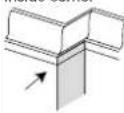 | Mitre angle | 30° right | 30° left |
| Bevel angle | 33,9° | 33,9° | |
| Moulding position | Top against fence | Bottom against fence | |
| Finished side | Keep left side of cut | Keep left side of cut | |
Outside corner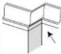 | Mitre angle | 30° left | 30° left |
| Bevel angle | 33,9° | 33,9° | |
| Moulding position | Bottom against fence | Top against fence | |
| Finished side | Keep right side of cut | Keep right side of cut | |
Note:
• These special stops cannot be used with 45^ crown moulding.
- Since most rooms do not have angles of exactly 90^ , fine tuning is needed and always take a test cut to confirm the correct angles.
Pullover Cut
WARNING:
- Never pull the cutting head assembly and spinning blade towards you during the cut. The blade may try to climb up on the top of the workpiece, causing the cutting head assembly and spinning blade to kick back.
2. Never lower the spinning saw blade down before pulling the cutting head to the front of the saw.
- Unlock the carriage 1 with the lock handle 2 and allow the cutting head assembly to move freely. (Fig. 6)
- Move the mitre handle and cutting head to the desired mitre angle and bevel angle according to the mitre cut and bevel cut procedures.
- Grasp the saw handle and pull the carriage forward until the centre of the saw blade is over the front of the work piece.
- Activate the switch, then press the blade guard lock lever to lower the cutting head down.
- When the saw reaches full speed, push the saw handle down slowly, cutting through the leading edge of the workpiece.
- Slowly move the saw handle toward the fence, completing the cut.
- Release the switch and allow the blade to stop spinning before allowing the cutting head to raise.
Depth adjustment normal Fig. 6.1
Sawing function 5 mm below the table top. (separate work pieces.)
Depth stop (1) housing-adjacent.
Stop screw (2) is used.
Setscrew (3) has no function.
Depth adjustment variable Fig.
Sawing function above the table top. (covered cuts)
Set depth stop (1) to the outside.
Set the setscrew (3) to the desired measurement and secure it with the counternut (4).
Make a test cut.
Stop screw (2) is not used.
Carrying the Tool
- Loosen the mitre lock knob and turn the table all the way to the right. Lock the table at 45° mitre angle.
- Push the cutting head backwards and lock the carriage.
- Lower the cutting head and push in the lock pin.
- Carry this mitre saw with the built-in carry handle and the side of the base.
Replacing of the saw blades, Fig. 7
Warning: Before replacing saw blades the switch must be turned off and the mains plug must be disconnected from the mains socket in order to avoid injuries by accidental start up of the machine.
- Disconnect the mains plug.
-
Set the sawing unit to position "mitre operation".
-
Unlock the movable saw blade cover (7) by pressing the blocker 3 (Fig. 1).
- When doing so lift the saw blade cover (7) to free the saw blade (8).
- Push the saw blade blocker A (fig. 7.1) until the saw blade locks in place.
- Loosening of the saw blade fixing screw with the provided socket wrench (B) (Attention, left-hand thread).
- Remove screw and saw blade flange.
- Remove the saw blade carefully. Attention: Danger of injuries from the saw blade.
- Set the new saw blade on the inner saw blade flange observing the correct size and rotational direction of the saw blade.
- Attach the outer saw blade flange and tighten die screw firmly.
- Set the saw blade cover back to the correct position.
Maintenance
WARNING: For your own safety, turn the switch off and remove the plug from the power source outlet before maintaining or lubricating your mitre saw.
General Maintenance
Occasionally use a cloth to wipe off chips and dust from the machine. Oil the rotary parts once a month to extend the tool life. Do not oil the motor.
Brush Inspection
Check the motor brushes after the first 50 hours of use for a new machine or after a new set of brushes have been installed. After the first check, examine them every 10 hours of use.
When the carbon is worn to 6 mm in length or if the spring or shunt wire is burned or damaged, replace both brushes. If the brushes are found serviceable after removing, reinstall them.
Electrical connection
The installed electric motor is completely wired ready for operation.
The customer's connection to the power supply system, and any extension cables that may be used, must conform with local regulations.
Important remark:
The motor is automatically switched off in the event of an overload. The motor can be switched on again after a cooling down period that can vary.
Defective electrical connection cables
Electrical connection cables often suffer insulation damage.
Possible causes are:
- Pinch points when connection cables are run through window or door gaps.
- Kinks resulting from incorrect attachment or laying of the connection cable.
• Cuts resulting from running over the connecting cable.
• Insulation damage resulting from forcefully pulling out of the wall socket.
• Cracks through aging of insulation.
Such defective electrical connection cables must not be used as the insulation damage makes them extremely hazardous.
Check electrical connection cables regularly for damage. Make sure the cable is disconnected from the mains when checking.
Electrical connection cables must comply with the regulations applicable in your country.
Single-phase motor
- The mains voltage must coincide with the voltage specified on the motor's rating plate.
- Extension cables up to a length of 25 m must have a cross-section of 1.5 mm2, and beyond 25 m at least 2.5 mm2.
- The connection to the mains must be protected with a 16 A slow-acting fuse.
Only a qualified electrician is permitted to connect the machine and complete repairs on its electrical equipment.
In the event of enquiries please specify the following data:
- Motor manufacturer
• Type of current of the motor
• Data recorded on the machine's rating plate
• Data recorded on the switch's rating plate
If a motor has to be returned, it must always be dispatched with the complete driving unit and switch.
Troubleshooting
| Problem Possible Cause | Help | |
| The motor does not run. | Faulty motor, power supply cable or plug.Burned out fuses. | Have the machine checked by skilled personnel. Do not try to repair the machine yourselves as it may be dangerous. Check the fuses and replace them if necessary. |
| The motor starts slowly and does not reach running speed. | Low power supply voltage. Damaged windings. Burned out capacitor. | Ask for the Electricity Board to check the voltage available. Have the machine motor checked by skilled personnel. Have the capacitor replaced by skilled personnel. |
| Excessive motor noise. | Damaged windings. Faulty motor. | Have the motor checked by skilled personnel. |
| The motor does not reach full power. | Overloaded circuit due to lighting, utilities or other motors. | Do not use other utilities or motors on the circuit to which the cutting-off machine is connected. |
| Motor overheats easily O | Overload of the motor; inadequate cooling of the motor | Prevent overloading the motor when cutting; remove dust from the motor to ensure an optimum cooling of the motor |
| Decrease in cutting power when sawing | The saw blade is too small (sharpened too often) | Re-adjust the end stop of the saw unit |
| The saw cut is rough or wavy | The saw blade is dull; the tooth shape is not suited to the thickness of the material | Re-sharpen the saw blade or use an appropriate saw blade |
| The work piece rips or splinters | The cutting pressure is excessive or the saw blade is not suited to the application | Use the correct saw blade |
Günzburger Straße 69,
D-89335 Ichenhausen
Cher client,
Günzburger Straße 69
D-89335 Ichenhausen
Stimato Cliente,
Günzburger Straße 69
D-89335 Ichenhausen
Değerli müşteri,
Günzburger Straße 69
D-89335 Ichenhausen
Dragi korisniče
Günzburger Straße 69
D-89335 Ichenhausen
Kedves Vásárló!
Günzburger Straße 69
D-89335 Ichenhausen
Arvoisa asiakas,
Günzburger Straße 69
D-89335 Ichenhausen
Kjære kunde,
Günzburger Straße 69
D-89335 Ichenhausen
Krere kunde,
Günzburger Straße 69
D-89335 Ichenhausen
Bäste kund,
Günzburger Straße 69
D-89335 Ichenhausen
Vážený zákazníku,
Günzburger Straße 69
D-89335 Ichenhausen
Lugupeetud klient,
Günzburger Straße 69
D-89335 Ichenhausen
Günzburger Straße 69
D-89335 ICHENHAUSEN
Spoštovani kupec
Želimo vam prijetno in uspešno delo z vašim novim strojem Toolson.
Nasvet;
Günzburger Straße 69
D-89335 Ichenhausen
Vážený zákazník!
Günzburger Straße 69
D-89335 Ichenhausen
Cijenjeni kupče,
Želimo Vam mnogo radosti i uspjeha u radu s Vašom novom mašinom TOOLSON.
NAPOMENA:
Proizvođač ovog uređaja u skladu s važećim zakonom o odgovornosti za poizvode ne preuzima nikakvu odgovornost za štete koje nastanu na ovom uređaju ili zbog ovog uređaja uslijed:
- nepropisnog rukovanja,
- nepoštovanja uputstava za rukovanje,
- popravki od strane trećih lica koja nisu ovlaštena stručna lica,
- ugradnje i zamjene neoriginalnih rezervnih dijelova,
- nenamjenske upotrebe,
- ispada električnog sistema zbog nepoštovanja električnih propisa i VDE odredbi 0100, DIN 57113 / VDE 0113.
MI VAM PREPORUČUJEMO:
Prije montaže i puštanja u rad pročitajte cjelokupni tekst uputstva za rukovanje.
Ovo uputstvo za rukovanje treba da Vam olakša upoznavanje Vaše mašine i korištenje njenih namjenskih mogućnosti upotrebe.
U uputstvu za rukovanje nalaze se važne napome- ne o tome kako da koristite mašinu sigurno, propisno i ekonomično i kako da izbjegavate opasnosti, uštedite na troškovima popravki, smanjite vremena ispada i povećate pouzdanost i životni vijek mašine. Dodatno uz sigurnosne odredbe ovog uputstva za rukovanje obavez- no morate poštovati propise Vaše zemlje koji se odnose na rad ovakve mašine. Sačuvajte uputstvo za rukovanje u blizini mašine, zaštićeno u od prljavštine i vlažnosti u plastičnoj vrećici. Njega prije početka rada mora pročitati i u potpunosti slijediti svaka osoba koja rukuje mašinom. Na mašini smiju raditi osobe kojima je objašnjena upotre- ba mašine i koje su dobile instrukcije o opasnostima koje su povezane s radom na mašini. Potrebno je pridržavati se pravila o minimalnoj starosnoj dobi rukovalaca.
Pored sigurnosnih napomena koje su sadržane u ovom uputstvu za rukovanje i posebnih propisa koji važe u Vašoj zemlji, pri radu s mašinama za obradu drveta moraju se poštovati i općepriznata tehnička pravila.
Legenda, sl. 1
1 vučni klizački
2 gornja zaštita za list pile
3 donja stezna poluga za zaštitu lista pile
4 prekidač za aktiviranje
5 ručka
6 motor
7 donja zaštita za list pile
8 list pile s vrhom za tvrde metale
9 dodirna površina
10 produžni nastavak
11 skala uglova
12 ručka za podešavanje
13 umetak stola
14 okretni sto
15 rupe za klin
16 podnožje
17 stezna čeljust
18 vreća za prašinu
19 ručka za nošenje
20 Laser
21 Tabela stezaljke ručka
| Tehnički podaci | |
| list pile prečnika mm 210 mm | |
| dimenzije D/Š/V 810 x 460 x 3 | 55 mm |
| težina 13,5 kg (neto ukupno) | |
| okretni sto prečnika 250 mm | |
| graničnici ugla za koso rezanje lijevo i desno | 0°, 15°, 22,5°, 30°, 45° |
| područje okretanja -45°/0°/45° | |
| područje nagiba | 0°–45° |
| maks. kapacitet | |
| poprečno rezanje s 90° | 58 x 340 mm |
| rezanje s iskošenjem pod 45° | 58 x 240 mm |
| koso rezanje pod 45° 32 x 340 mm | |
| kombinovano rezanje s 45° 32 x 240 mm | |
| pogon | |
| Motor V/Hz | 230-240V ~ / 50 Hz |
| primljena snaga P1 1500 W (S6 25%) | |
| broj okretaja | 5000/min |
| Klasa lasera 2 | |
| Zadržavamo pravo na tehničke izmjene! | |
Nivo buke pri rezanju:
$$ L _ {D A}: 9 9, 6 \mathrm{dB(A)} K = 3 \mathrm{dB(A)} $$
$$ L _ {w A}: 1 1 2, 6 \mathrm{dB(A)} K = 3 \mathrm{dB(A)} $$
Vibracija:
Vibracija: 4,51m/s²
$$ K = 1. 5 \mathrm{m} / \mathrm{s} ^ {2} $$
- Navedena vrijednost emisije pri vibriranju izmjerena je prema normiranom kontrolnom postupku i može se koristiti radi poređenja električnog alata s drugim električnim alatom;
-
Navedena vrijednost emisije pri vibriranju može se koristiti i za prvu procjenu opterećenja.
-
Upozorenje: Vrijednost emisije pri vibriranju tokom stvarnog korištenja električnog alata može se razlikovati od navedene vrijednosti, zavisno od vrste i načina na koji se električni alat koristi.
- Pokušajte držati opterećenje uslijed vibriranja što je moguće manjim. Mjere koje se mogu preduzeti radi smanjenje opterećenja zbog vibriranja su npr. nošenje rukavica pri upotrebi alata i ograničenje vremena rada. Pri tome se u obzir moraju uzeti sve faze radnog ciklusa (npr. vremena tokom kojih je električni alat isključen i ona tokom kojih je uključen, ali radi bez opterećenja).
Opće napomene
Günzburger Straße 69
D-89335 Ichenhausen
Уважаеми клиенти,
Günzburger Straße 69
D-89335 Ichenhausen
Günzburger Straße 69
D-89335 Ichenhausen
Geachte klant,
| 89/686/EC_96/58/EC | |
| X 2006/42/EC | |
| Annex IVNotified Body:Notified Body No.:Reg. No.: | |
| 2000/14/EC_2005/88/EC | |
| Annex V | |
| Annex VINoise:Notified Body:Notified Body No.: | |
| 2010/26/EC | |
| Emission. No: | |
Standard references: EN 61029-1:2009/A11:2010; EN 61029-2-9:2012/A11:2013; EN 55014-1/A2:2011; EN 55014-2/A2:2008; EN 61000-3-2/A2:2009; EN 61000-3-11:2000
Garantie DE
Apparent defects must be notified within 8 days from the receipt of the goods. Otherwise, the buyer's rights of claim due to such defects are invalidated. We guarantee for our machines in case of proper treatment for the time of the statutory warranty period from delivery in such a way that we replace any machine part free of charge which provably becomes unusable due to faulty material or defects of fabrication within such period of time. With respect to parts not
manufactured by us we only warrant insofar as we are entitled to warranty claims against the upstream suppliers. The costs for the installation of the new parts shall be borne by the buyer. The cancellation of sale or the reduction of purchase price as well as any other claims for damages shall be excluded.
Garantie FR
- KGZ3400
- DE
- FR
- Verehrter Kunde,
- Manufacturer:
- Dear customer,
- Advice:
- Recommendations:
- Know your Pullover Mitre Saw (Fig. 1)
- Noise level during working
- General Notes
- General Safety Rules
- Additional Safety Rules For Mitre Saws
- Proper use
- Remaining hazards
- Assembly
- Installing the Dust Bag (Fig. 2)
- Setting the Tool
- Note:
- Installation of the Angle Fence at 45° Left. Fig.4
- Installation of the Contact Surface,
- Connecting to the Power Supply
- Using an Extension Lead
- Mounting the Tool
- Operating the Tool
- Basic Pullover Mitre Saw Operations
- Cross-cutting (Fig. 1, 1.2, 6)
- Mitre cut 0°-45° (Fig. 1, 1.2, 3)
- Bevel Cut
- Compound Cut
- Base Moulding
- Crown Moulding Cut
- Pullover Cut
- WARNING:
- Never lower the spinning saw blade down before pulling the cutting head to the front of the saw.
- Depth adjustment normal Fig. 6.1
- Depth adjustment variable Fig.
- Carrying the Tool
- Replacing of the saw blades, Fig. 7
- Maintenance
- General Maintenance
- Brush Inspection
- Electrical connection
- Important remark:
- Defective electrical connection cables
- Single-phase motor
- Cher client,
- Stimato Cliente,
- Değerli müşteri,
- Dragi korisniče
- Kedves Vásárló!
- Arvoisa asiakas,
- Kjære kunde,
- Krere kunde,
- Bäste kund,
- Vážený zákazníku,
- Lugupeetud klient,
- Nasvet;
- Vážený zákazník!
- Cijenjeni kupče,
- NAPOMENA:
- MI VAM PREPORUČUJEMO:
- Legenda, sl. 1
- Opće napomene
- Уважаеми клиенти,
- Geachte klant,
- Garantie DE
- Garantie FR
Brand : Toolson
Model : KGZ3400
Category : Saw