CCSE-3500.420 - Electric saw MSW - Free user manual and instructions
Find the device manual for free CCSE-3500.420 MSW in PDF.

| Product Type | Electric Concrete Saw |
| Model | MSW-CCSE-3500.420 |
| Brand | MSW |
| Rated Voltage | 230 V~ / 50 Hz |
| Rated Power | 3500 W |
| No-Load Speed | Up to 4000 rpm |
| Maximum Disc Diameter | 420 mm |
| Maximum Cutting Depth | 155 mm |
| Dimensions (L x D x H) | 240 x 800 x 420 mm |
| Weight | 15.8 kg |
| Suitable Materials | Concrete, metal, tile, stone |
| Blade Type | Diamond blade (disc) |
| Water Supply System | Yes, for wet cutting |
| Protection | Adjustable protective hood, spindle lock |
| Switch | With anti-restart button |
| Carbon Brushes | Replaceable, replacement threshold at 6-7 mm |
| Maintenance | Regular cleaning, inspection of screws and blades |
| Noise Level | Loud - hearing protection mandatory |
| Required Protective Equipment | Goggles, dust mask, gloves, foot protection |
| Warranty | Complies with current safety standards |
| Manual Pages | 352 pages (multilingual) |
Frequently Asked Questions - CCSE-3500.420 MSW
User questions about CCSE-3500.420 MSW
0 question about this device. Answer the ones you know or ask your own.
Ask a new question about this device
Download the instructions for your Electric saw in PDF format for free! Find your manual CCSE-3500.420 - MSW and take your electronic device back in hand. On this page are published all the documents necessary for the use of your device. CCSE-3500.420 by MSW.
USER MANUAL CCSE-3500.420 MSW

natural_image
Simple line drawing of a circle crossed over a horizontal bar with triangular supports (no text or symbols)
natural_image
Simple line drawing of a beam with supports and an arrow indicating upward motion (no text or symbols)natural_image
Diagram of a cutting tool crossed over a gear with an arrow indicating direction (no text or symbols)
natural_image
Diagram of a cutting tool using a saw blade on a surface, showing motion direction (no text or symbols)
natural_image
Line drawing of a person's legs and feet interacting with a bicycle (no text or symbols)This User Manual has been translated using machine translation. We have made every effort to ensure the translation is accurate, but please note that automated translations are not perfect and are not meant to replace human translators. The official version of the User Manual is in English. Any differences between the translated version and the original English are not legally binding. If you have any questions about the accuracy of the translation, please refer to the English version, which is the official reference. More language versions are available upon request via info@expondo.com.
Technical data
| Parameter description Parameter value | |
| Product name Concrete cut-off saw | |
| Model | MSW-CCSE-3500.420 |
| Rated voltage [V~] / frequency [Hz] 230 / 50 | |
| Rated power [W] 3500 | |
| No-load speed [RPM] Max 4000 | |
| Max disc dia. [cm] 420 | |
| Max cutting depth [mm] 155 | |
| Dimensions [width x depth x height; mm] 240 x 800 x 420 | |
| Weight [kg] 15.8 | |
1. General description
The user manual is designed to assist in the safe and trouble-free use of the device. The product is designed and manufactured in accordance with strict technical guidelines, using state-of-the-art technologies and components. Additionally, it is produced in compliance with the most stringent quality standards.
DO NOT USE THE DEVICE UNLESS YOU HAVE THOROUGHLY READ AND UNDERSTOOD THIS USER MANUAL.
To increase the product life of the device and to ensure trouble-free operation, use it in accordance with this user manual and regularly perform maintenance tasks. The technical data and specifications in this user manual are up to date. The manufacturer reserves the right to make changes associated with quality improvement. The device is designed to reduce noise emission risks to a minimum, taking into account technological progress and noise reduction opportunities.
Legend

The product satisfies the relevant safety standards.

Read instructions before use.

The product must be recycled.

WARNING! or CAUTION! or REMEMBER! Applicable to the given situation.
(general warning sign)

Use ear protection. Exposure to loud noise may result in hearing loss.

Wear protective goggles.

Wear a dust mask (respiratory tract protection).

Wear protective gloves.

Wear foot protection.

ATTENTION! Electric shock warning!

ATTENTION! Loud noise warning!

PLEASE NOTE! Drawings in this manual are for illustration purposes only and in some details may differ from the actual product.
2. Usage safety

ATTENTION!
Read all safety warnings and all instructions. Failure to follow the warnings and instructions may result in electric shock, fire and/or serious injury or even death.
The terms "device" or "product" are used in the warnings and instructions to refer to:
Concrete cut-off saw
2.1. Electrical safety
a) The plug must fit the socket. Do not modify the plug in any way. Using original plugs and matching sockets reduces the risk of electric shock.
b) Avoid touching earthed elements such as pipes, heaters, boilers and refrigerators. There is an increased risk of electric shock if the earthed device is exposed to rain, comes into direct contact with a wet surface or is operating in a damp environment. Water getting into the device increases the risk of damage to the device and of electric shock.
c) Do not touch the device with wet or damp hands.
d) Use the cable only for its designated use. Never use it to carry the device or to pull the plug out of a socket. Keep the cable away from heat sources, oil, sharp edges or moving parts. Damaged or tangled cables increase the risk of electric shock.
e) If working with the device outdoors, make sure to use an extension cord suitable for outdoor use. Using an extension cord suitable for outdoor use reduces the risk of electric shock.
f) If using the device in a damp environment cannot be avoided, a residual current device (RCD) should be applied. The use of an RCD reduces the risk of electric shock.
g) Do not use the device if the power cord is damaged or shows obvious signs of wear. A damaged power cord should be replaced by a qualified electrician or the manufacturer's service centre.
h) To avoid electric shock, do not immerse the cord, plug or device in water or other liquids. Do not use the device on wet surfaces.
i) ATTENTION! DANGER TO LIFE! While cleaning, never immerse the device in water or other liquids.
j) Do not use in very humid environments or in the direct vicinity of water tanks.
k) Prevent the device from getting wet. Risk of electric shock!
2.2. Safety in the workplace
a) Make sure the workplace is clean and well lit. A messy or poorly lit workplace may lead to accidents. Try to think ahead, observe what is going on and use common sense when working with the device.
b) Do not use the device in a potentially explosive environment, for example in the presence of flammable liquids, gases or dust. The device generates sparks which may ignite dust or fumes.
c) If you discover damage or irregular operation, immediately switch the device off and report it to a supervisor without delay.
d) If you are unsure about whether the product is operating correctly or if you find damage, please contact the manufacturer's service centre.
e) Only the manufacturer's service centre may make repairs to the product. Do not attempt to make repairs yourself!
f) In case of fire, use a powder or carbon dioxide (CO _2 ) fire extinguisher (one intended for use on live electrical devices) to put it out.
g) Children or unauthorised persons are forbidden to enter a work station. A distraction may result in loss of control over the device.
h) Use the device in a well-ventilated space.
i) The device produces dust and debris during operation. It is important to protect bystanders from their harmful effects.
j) If devices are provided for the connection of dust extraction and collection facilities, ensure these are connected and properly used. Use of dust collection can reduce dust-related hazards.
k) Regularly inspect the condition of the safety labels. If the labels are illegible, they must be replaced.
I) Please keep this manual available for future reference. If this device is passed on to a third party, the manual must be passed on with it.
m) Keep packaging elements and small assembly parts in a place not available to children.
n) Keep the device away from children and animals.
o) If this device is used together with another equipment, the remaining instructions for use shall also be followed.

Remember! When using the device, protect children and other bystanders.
2.3. Personal safety
a) Do not use the device when tired, ill or under the influence of alcohol, narcotics or medication which can significantly impair the ability to operate the device.
b) The machine may be operated by physically fit persons who are able to handle the machine, are properly trained, who have reviewed this operating manual and have received training in occupational health and safety.
c) When working with the device, use common sense and stay alert. Temporary loss of concentration while using the device may lead to serious injuries.
d) Use personal protective equipment as required for working with the device, specified in section 1 "Legend". The use of correct and approved personal protective equipment reduces the risk of injury.
e) To prevent the device from accidentally switching on, make sure the switch is on the OFF position before connecting to a power source.
f) Do not overestimate your abilities. When using the device, keep your balance and remain stable at all times. This will ensure better control over the device in unexpected situations.
g) Do not wear loose clothing or jewellery. Keep hair, clothes and gloves away from moving parts. Loose clothing, jewellery or long hair may get caught in moving parts.
h) Remove all adjusting tools or spanners before turning the device on. A tool or spanner left in the revolving part of the device may cause injury.
i) The device is not a toy. Children must be supervised to ensure that they do not play with the device.
j) Do not put your hands or other items inside the device while it is in use!
2.4. Safe device use
a) Do not overload the device. Use the appropriate tools for the given task. A correctly-selected device will perform the task for which it was designed better and in a safer manner.
b) Do not use the device if the "ON/OFF" switch does not function properly (does not switch the device on and off). Devices which cannot be switched on and off using the "ON/OFF" switch are hazardous, should not be operated and must be repaired.
c) Make sure the plug is disconnected from the socket before attempting any adjustments, accessory replacements or before putting the device aside. Such precautions will reduce the risk of accidentally activating the device.
d) When not in use, store in a safe place, away from children and people not familiar with the device who have not read the user manual. The device may pose a hazard in the hands of inexperienced users.
e) Keep the device in perfect technical condition. Before each use check for general damage, especially check moving components for cracked parts or elements, and for any other conditions which may impact the safe operation of the device. If damage is discovered, hand over the device for repair before use.
f) Keep the device out of the reach of children.
g) Device repair or maintenance should be carried out by qualified persons, only using original spare parts. This will ensure safe use.
h) To ensure the operational integrity of the device, do not remove factory-fitted guards and do not loosen any screws.
i) When transporting and handling the device between the warehouse and the destination, observe the occupational health and safety principles for manual transport operations which apply in the country where the device will be used.
j) Avoid situations where the device stops working during use due to excessive loading. This may result in overheating of the drive elements and damage to the device.
k) Do not touch articulated parts or accessories unless the device has been disconnected from the power source.
I) Do not leave this appliance unattended while it is in use.
m) Clean the device regularly to prevent stubborn grime from accumulating.
n) Do not work on two workpieces at the same time.
o) The device is not a toy. Cleaning and maintenance may not be carried out by children without supervision by an adult person.
p) Do not run the device when empty.
q) It is forbidden to interfere with the structure of the device in order to change its parameters or construction.
r) Keep the device away from sources of fire and heat.
s) Do not cover the ventilation openings!
t) Keep cutting tools sharp and clean. Properly maintained cutting tools with sharp cutting edges are less likely to bind and are easier to control.
u) Grinding wheels shall not be used.
v) Do not operate with the fixed shield removed.
w) Do not start the cutter when the cutting is in contact with the workpiece.
x) After the cutting machine is powered off, do not put down the cutting machine before the cutting blade stops completely, and do not use any external force to force the diamond saw blade to stop running.
y) Before replacing the cutting blade, adjusting the cutting depth or water pipe, adjusting any part of the machine or repairing the cutting machine, the plug should be pulled off from the power supply and the diamond saw blade should be in a static state.
z) When the diamond saw blade is likely to cut to the dark wire or its own wire for operation, the power tool can only be held through the insulated holding surface. The diamond saw blade touching the live wire may make the exposed metal parts of the electric tool live and the operator may be exposed to the risk of electric shock.
aa) Take extra care when making "blind cuts" into walls or other blind areas. Diamond saw blades may cut gas or water pipes, wires or objects rebounded from them.
bb) Keep your hands away from the cutting area or diamond saw blade at all times. Your other hand always holds the assist handle. If you hold the cutter with both hands, you will not be hurt by the saw blade.
cc) Do not touch the bottom of the workpiece. The shield cannot protect the saw blade under the workpiece.
dd) Always use a diamond saw blade with the proper size and axis shape (diamond or circular). If the diamond saw blade does not match with the clamping parts of the cutting machine, it will cause eccentric operation and cause out of control.
ee) Do not use damaged and non-dimensional washers and bolts. The use of damaged or non-conforming gaskets and bolts can result in uncontrolled operation.

ATTENTION! Despite the safe design of the device and its protective features, and despite the use of additional elements protecting the operator, there is still a slight risk of accident or injury when using the device. Stay alert and use common sense when using the device.
3. Use guidelines
The product is designed for cutting concrete, cutting metal, polishing, and other purposes.
The user is liable for any damage resulting from unintended use of the device.
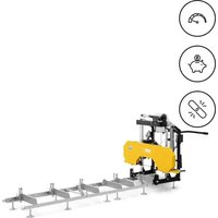
3.1. Device description

| No. | Description |
| 1 | Sheath |
| 2 | Switch |
| 3 | Bracket |
| 4 | Water |
| 5 | Protective |
| 6 | Blade |
| 7 | Dust |
| 8 | Handle |
| 9 Saw blade locking nut | |
| 10 | Wheel |
| 11 | Brush |
| 12 | Rear |
3.2. Preparing for use
PRIOR CHECKING
1. Power Source
Ensure that the power source you intend to use matches the power requirements specified on the product's nameplate.
2. Power Switch
Confirm that the power switch is in the OFF position. If the tool is plugged in while the switch is ON, it may start operating immediately, which could result in a serious accident.
3. Extension Cord
If the work area is far from the power source, use an extension cord with sufficient thickness and rated capacity. Keep the extension cord as short as possible to reduce power loss.
4. Checking and Installing the Diamond Wheel
Verify that the diamond wheel is the specified type and that it is free of cracks, breaks, or bending. Ensure the wheel is securely installed. For installation details, refer to the section "3.3. Assembling the device".
5. Wheel Guard Knob
Make sure the knob securing the wheel guard is properly tightened. A loose knob may cause the wheel guard to shift or detach, resulting in potential injury to the operator.
PRECAUTIONS
- DANGER: Keep hands away from the cutting area and blade. Always keep your second hand on the auxiliary handle or motor housing. Holding the saw with both hands helps prevent injury from the blade.
- Never engage the spindle lock button while the machine is running.
-
Only attach tools specified by the manufacturer—use only diamond or cutting wheels as recommended. Do not operate the cutter while applying water.
-
Always inspect the diamond wheel before use. Do not use it if it is cracked, broken, or bent. Start the machine carefully and check for any abnormalities.
- Do not use the diamond wheel to cut metal. Doing so will reduce its service life or cause it to break.
- Begin cutting only after the tool has reached its maximum rotation speed.
- Avoid applying excessive force, which can overload the motor and reduce efficiency and service life. Only cut concrete, tile, or stone to a depth of 100 mm or less. For deeper cuts, make 2 to 3 passes. Cutting deeper than 100 mm in one pass reduces the diamond wheel's service life and may cause motor failure.
- Do not use this machine to cut asbestos.
- When using a cutting wheel that produces sparks, cover the dust collection adapter with a rubber cap and always wear protective goggles.
- Never use damaged or incorrect blade washers or bolts. These parts are specially designed for your saw to ensure optimal performance and safe operation.

CAUTION! Always unplug the disc cutter before changing blades, servicing, cleaning, or adjusting.
3.3. Assembling the device
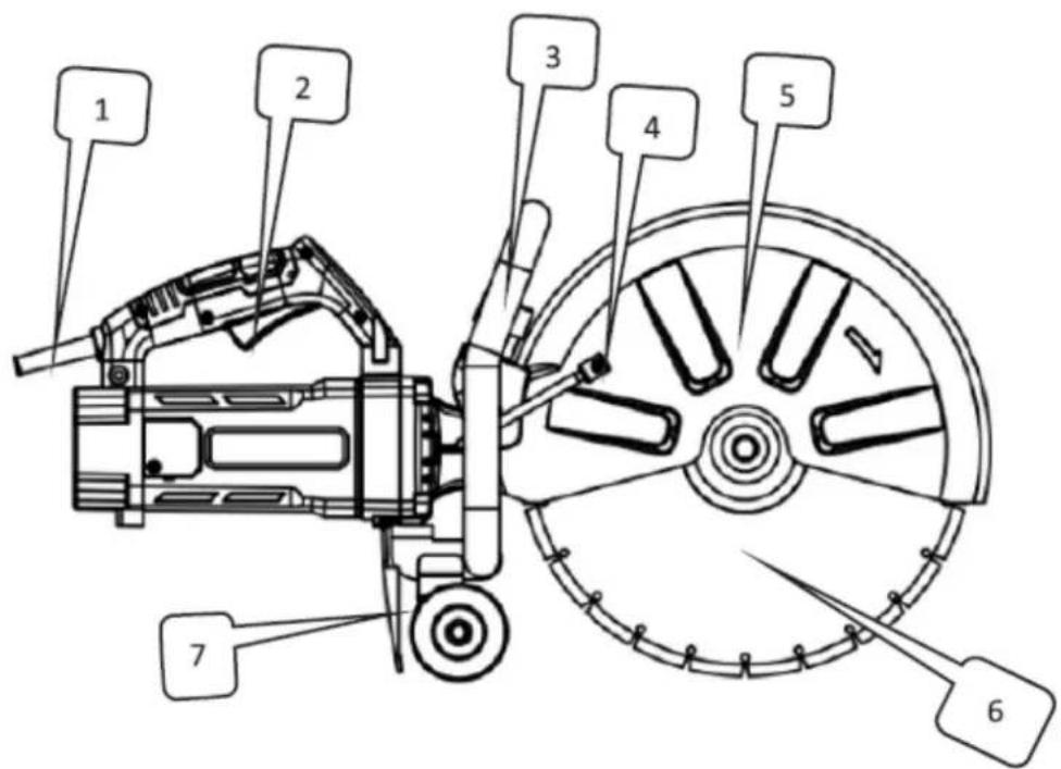
INSTALLING/REMOVING DIAMOND WHEEL

CAUTION! For your safety, do not attempt to cut tiles or other materials until the tool is fully assembled. Carefully read the operating instructions beforehand to understand the machine's functions and avoid risks from incorrect operation. Ensure the saw blade is properly installed between the inner and outer flanges (pressure plates).
- Turn off the tool switch and unplug it from the power socket.
- While pressing the spindle lock button with one hand, use the provided wrench to loosen the bolt (reverse-threaded) by turning it clockwise.
- Remove the elastic washer and outer flange (pressure plate).
- Place the saw blade onto the step of the inner flange (pressure plate). Note: Some blades may require a small inner washer to ensure firm contact with the flange.
- Reinstall the outer flange (pressure plate) onto the output shaft.
- Place a small elastic pressure plate.
- While pressing the self-locking button, tighten the bolt (reverse-threaded) anticlockwise with the wrench.
- Gently rotate the saw blade to ensure the self-locking pin has released and that the blade rotates smoothly.
A- Inner washer
B- Anticlockwise
C-Clockwise

CAUTION!
- The direction of the arrow on the saw blade must match the rotation direction indicated on the machine cover.
• For your safety, always remove the wrench immediately after use and return it to the toolbox.
• Check blade flanges for debris before installing any new blade. - Do not use dull or broken blades.
• Check blades frequently for their condition and signs of wear. - Replace damaged or worn blades immediately.
• Always ensure safe handling and disposal of excess material.
3.4. Device use
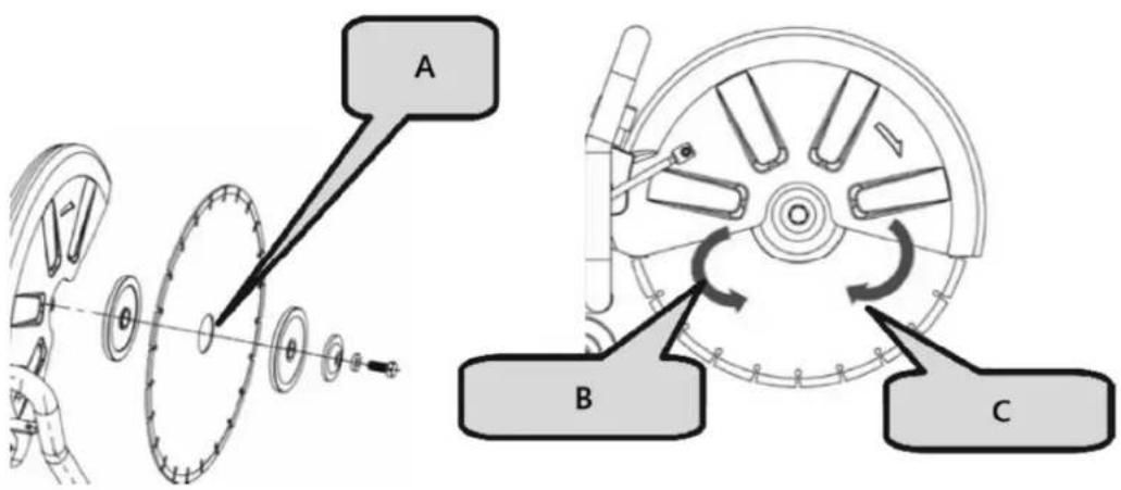
ADJUSTMENT OF SHIELD ANGLE
- When cutting an irregular workpiece and interference occurs between the shield and the workpiece, adjust the angle of the protective cover to best accommodate both cutting and protection requirements.
- Loosen the plastic knob, rotate the protective cover to a suitable position, then tighten the plastic knob to secure it.
A- Plastic knob
PRACTICAL APPLICATION
- The power supply voltage must match the voltage indicated on the tech plate.
- Before operation, inspect the cutting blade. It must be installed correctly and rotate freely. Conduct a no-load test for at least 30 seconds. Do not use damaged, deformed, or vibrating blades—damaged blades may break and cause injury.
- Waste dust from processing materials that contain lead-based pigments, minerals, or metals can be hazardous to health. Ensure proper ventilation in the workplace. Wearing a P2-grade filter mask is recommended.
REPLACEMENT OF CARBON BRUSH
- Loosen the screws on the brush holder cover.
- Remove the brush holder cover.
- Open the coil spring.
- Use pointed nose pliers to remove the carbon brush buckle and take out the carbon brush.
- Install the original carbon brush and insert the buckle into the brush holder.
- Cover the brush holder cover and screw in the screws to secure it.

NOTICE!
Check the size of the carbon brush after prolonged operation. If it is less than 7 mm, replace it promptly. Failure to do so may result in damage to the motor.
Switch Operation
- Power on: Press the anti-self-locking button, then press the switch button.
- Shut down: Release the switch button.
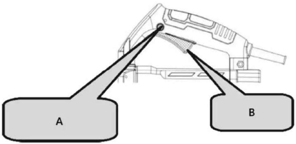
A- Anti-self-locking button
B- Switch

CAUTION!
• Always check the diamond wheel before starting work.
• Never use a diamond wheel that is cracked, broken, or bent.
- Do not apply water or coolant to the diamond wheel.
• Start cutting only when the diamond wheel reaches maximum speed.
• If the diamond wheel seizes or you hear abnormal noise, immediately turn off the power.
- Never use the diamond wheel to cut zigzag or curved lines. Do not use the side surface of the diamond wheel or attempt inclined cuts.
- Excessive force to align the blade with the marked line can overload and damage the motor, overheat the diamond wheel, and shorten its lifespan.
- Keep the power cord away from the diamond wheel during operation.
- When work is finished, turn off the power and unplug the tool.
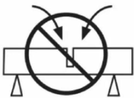
• Support the workpiece to ensure a predictable cutting path and that the cut remains open.
natural_image
Simple line drawing of a circle with diagonal lines and arrows, resting on a horizontal bar with supports (no text or symbols)
natural_image
Simple line drawing of a rectangular block with supports and an arrow indicating upward motion (no text or symbols)- Ensure the blade is not in contact with any object when starting the machine.
• Always cut at the maximum speed.
• Start cutting smoothly, letting the tool do the work without applying excessive pressure.
- Move the blade gently forward and backward to reduce contact area, helping lower blade temperature and ensuring efficient cutting.
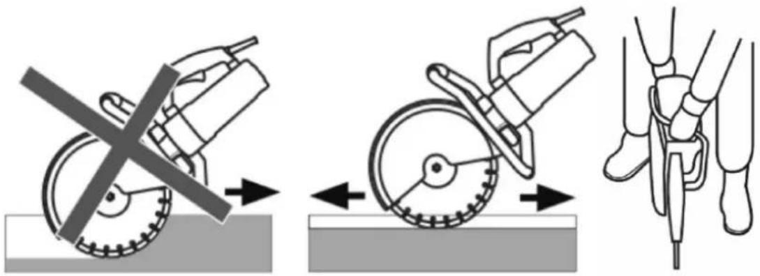
• Feed the machine straight in line with the blade. Side pressure can damage the blade and is dangerous.
3.5. Cleaning and maintenance
a) Unplug the mains plug and allow the device to cool completely before each cleaning, adjustment or replacement of accessories, or if the device is not being used.
- Wait for the rotating elements to stop.
b) Always unplug the device before cleaning or putting it away.
c) Use only non-corrosive cleaners to clean the surface.
d) After cleaning the device, all parts should be dried completely before using it again.
e) Store the unit in a dry, cool place, free from moisture and direct exposure to sunlight.
f) Do not spray the device with a water jet or submerge it in water.
g) The device must be regularly inspected to check its technical efficiency and spot any damage.
h) Use a soft, damp cloth for cleaning.
i) Do not use sharp and/or metal objects for cleaning (e.g. a wire brush or a metal spatula) because they may damage the surface material of the appliance.
j) Do not clean the device with an acidic substance, agents of medical purposes, thinners, fuel, oils or other chemical substances because it may damage the device.
1. Inspecting the Diamond Wheel
A worn diamond wheel can overload the motor and reduce working efficiency. Replace it with a new one when necessary.
2. Inspecting the Mounting Screws
Regularly check all mounting screws to ensure they are properly tightened. Retighten any loose screws immediately to avoid serious hazards.
3. Motor Maintenance
Take care to ensure the motor windings are not damaged or exposed to oil or water.
4. Keep the Tool Clean and Free from Debris
Avoid using cleaning agents that contain benzene, trichloroethylene, chloride, or ammonia, as these may damage plastic components.
5. Malfunction Handling
If an electrical or mechanical malfunction occurs, immediately switch off the tool and disconnect the plug.
6. Excessive Sparking
Excessive sparking may indicate the motor is dirty or that the carbon brushes are worn out. Check for wear and replace the brushes when they are shorter than 1/4" (6 mm).

NOTICE!
If the machine is used as a road cutting machine or for long-distance cutting, pay attention to the following:
- It is recommended to let the machine rest or idle for 5–10 minutes after continuous cutting.
- When cutting, avoid applying excessive force. Simply guide the cutting direction with light pressure to ensure easy operation and better durability.
- Adopt the correct cutting method: cutting → idling → re-cutting.
- Let the machine idle for a short time before shutting it down to protect the motor.
- Following these tips will help you achieve efficient and smooth cutting.
DISPOSING OF USED DEVICES
Do not dispose of this device in municipal waste systems. Hand it over to an electric and electrical device recycling and collection point. Check the symbol on the product, instruction manual and packaging. The plastics used to construct the device can be recycled in accordance with their markings. By choosing to recycle you are making a significant contribution to the protection of our environment.
Contact local authorities for information on your local recycling facility.
The dust may contain harmful substances and should not be disposed of as ordinary waste. It must be taken to special waste recycling stations for proper disposal.
3.6. Parts list
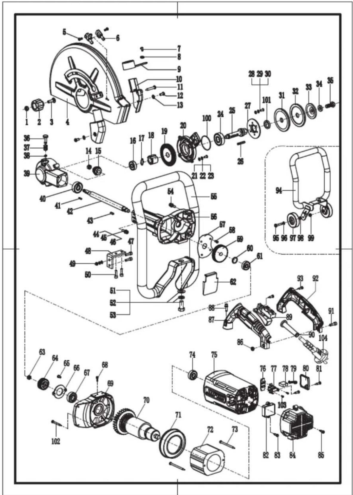
| No. | Description | Qty. | No. | Description | Qty. | No. | Description | Qty. |
| 1 | M8 nut 1 | 39 | Head shell 1 71 Wind shield 1 | |||||
| 2 | Plastic knob | 1 | 40 | 6301 bearing 1 | 72 | Stator 1 | ||
| 3 | M8X35 screw | 1 | 41 | Square key 3X3X13.6 1 73 | 5X80 screw | 2 | ||
| 4 | Protective cover | 1 | 42 | Spindle | 1 | 74 | 6201 bearing 1 | |
| 5 | 5X10 screw | 2 | 43 | Square key 4X4X13.6 1 75 | Motor cover | 1 | ||
| 6 | Water nozzle | 1 | 44 | M5X20 screw | 4 | 76 Fixing clip | ||
| 7 | 4X10 screw | 1 | 45 | Φ 5 spring washer | 4 | 77 | Brush holder 2 | |
| 8 | Φ 4 flat washer | 1 | 46 | Φ 5 flat washer | 4 | 78 | Carbon brush 2 | |
| 9 | Dust outlet cover | 47 | M6X35 screw | 2 79 Coil spring 2 | ||||
| 10 | Dust cover | 1 | 48 | Right-angle fastener | 1 | 80 Brush cover | ||
| 11 | 4X30 screw | 1 | 49 | M6 nut | 2 81 4X14 screw 6 | |||
| 12 | 4X10 screw | 2 | Φ 6 spring washer | 2 | 82 | Starter 1 | ||
| 13 | Φ 4 flat washer | 2 | Φ 6 flat washer | 2 | 83 | 4X14 screw 2 | ||
| 14 | M8X1.25 nut | 1 | 50 | M6X16 screw | 2 84 Rear cover 1 | |||
| 15 | Small gear | 1 | Φ 6 spring washer | 2 | 85 | 5X20 screw 4 | ||
| 16 | 6200 bearing | 1 | Φ 6 flat washer | 2 | 86 | M6 nut 1 | ||
| 17 | Φ 14 shaft clamp | 1 | 51 | M12X25 hexagon bolt | 1 | 87 | Switch handle (left) 1 | |
| 18 | Large gear | 1 | 52 | Φ 12 spring washer | 1 | 88 | M5X25 screw 4 | |
| 19 | Large gear | 1 | 53 | Φ 12 flat washer | 1 | Φ 5 spring washer 4 | ||
| 20 | Head cover | 1 | 54 | M5X25 screw | 4 | Φ 5 flat washer 4 | ||
| 21 | 5X14 screw | 4 | Φ 5 spring washer | 4 | 89 | Switch 1 | ||
| 22 | Φ 5 spring washer | 4 | Φ 5 flat washer | 4 | 90 | Sheath 1 | ||
| 23 | Φ 5 flat washer | 4 | 55 | Armrest | 1 | 91 | M6X25 screw | |
| 24 | 6302 bearing | 1 | 56 | Gear box | 1 | 92 Switch handle (right) 1 | ||
| 25 | Small drive shaft | 1 | 57 | Oil baffle | 1 93 4X16 screw 5 | |||
| 26 | Square key 4X4X30 | 1 | 58 | 4X10 screw | 4 | 94 Bracket | ||
| 27 | 6302 bearing pressing | 1 | 59 | Flat gear | 1 | 95 M8X45 hexagon bolt 2 | ||
| 28 | 5X14 screw | 3 | 60 | Flat washer Φ 23 X Φ 15 X 1 | 1 | 96 | Φ 8 flat washer 1 | |
| 29 | Φ 5 spring washer | 3 | 61 | 6200 bearing 1 | 97 | Wheel 2 | ||
| 30 | Φ 5 flat washer | 3 | 62 | Dust shield | 1 | 98 | Φ 8X8 spacer 1 | |
| 31 | Lower pressing plate | 1 | 63 | M8X1.25 nut | 1 99 M8 nut 2 | |||
| 32 | Upper pressing plate | 1 | 64 | Small gear | 1 | 100 | 60X2 sealing ring 1 | |
| 33 | Elastic pressing plate | 1 | 65 | 4X10 screw | 2 | 101 | 24X35X7 oil seal 1 | |
| 34 | Φ 10 flat washer | 1 | 66 | Bearing pressing plate | 1 | 102 | 5X35 screw 4 | |
| 35 | M10X25 screw | 1 | 67 | 6202 bearing 1 | 103 | 4X8 screw 4 | ||
| 36 | Pin | 1 | 68 | 4X10 screw | 1 | 104 Cable 1 | ||
| 37 | Spring | 1 | 69 | Connecting cover | 1 | |||
| 38 | Snap ring Φ 6 | 1 | 70 | Rotor | 1 | |||


natural_image
Simple line drawing of a circle crossed over a horizontal bar with triangular supports (no text or symbols)
natural_image
Simple line drawing of a beam with supports and an arrow indicating upward motion (no text or symbols)natural_image
Diagram of a cutting tool crossed over a gear with an arrow indicating direction (no text or symbols)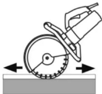
natural_image
Diagram of a cutting tool using a saw blade on a workpiece, with directional arrows indicating motion (no text or symbols)
natural_image
Line drawing of a person's lower body and foot, showing mechanical components (no text or symbols)
natural_image
Simple line drawing of a circular object with diagonal lines and arrows, resting on a horizontal beam (no text or symbols)
natural_image
Simple line drawing of a beam with supports and an arrow indicating upward motion (no text or symbols)
| Non. | Description |
| 1 | Gaine |
| 2 | Changer |
| 3 | Support |
APPLICATION PRATIQUE
natural_image
Simple line drawing of a circle crossed over a horizontal bar with triangular supports (no text or symbols)
natural_image
Simple line drawing of a beam with supports and an arrow indicating upward motion (no text or symbols)
natural_image
Simple line drawing of a circle crossed over a horizontal bar with triangular supports (no text or symbols)
natural_image
Simple line drawing of a beam with supports and an arrow indicating upward motion (no text or symbols)natural_image
Diagram of a cutting tool crossed over a gear with an arrow indicating direction (no text or symbols)
natural_image
Diagram of a cutting tool using a saw blade on a surface, showing motion direction (no text or symbols)
natural_image
Line drawing of a person's legs and feet interacting with a bicycle (no text or symbols)
natural_image
Simple line drawing of a circle crossed over a horizontal bar with triangular supports (no text or symbols)
natural_image
Simple line drawing of a beam with supports and an arrow indicating upward motion (no text or symbols)
natural_image
Simple line drawing of a circular object with diagonal lines and arrows, resting on a horizontal beam with supports (no text or symbols)
natural_image
Simple line drawing of a beam with supports and an arrow indicating upward motion (no text or symbols)
natural_image
Simple line drawing of a circular object with diagonal lines and arrows, resting on a horizontal beam with supports (no text or symbols)
natural_image
Simple line drawing of a beam with supports and an arrow indicating upward motion (no text or symbols)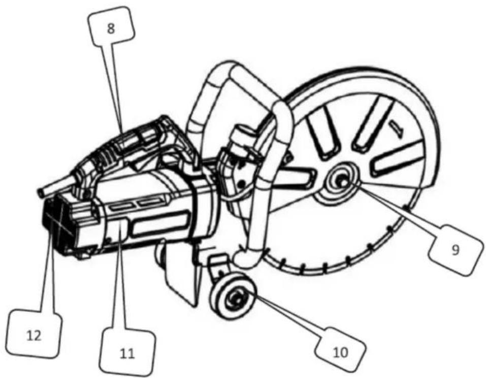
natural_image
Simple line drawing of a circular object with diagonal lines and arrows, resting on a horizontal beam (no text or symbols)
natural_image
Simple line drawing of a beam with supports and an arrow indicating upward motion (no text or symbols)
natural_image
Simple line drawing of a circle crossed over a horizontal bar with triangular supports (no text or symbols)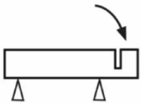
natural_image
Simple line drawing of a beam with supports and an arrow indicating upward motion (no text or symbols)natural_image
Diagram of a cutting cutter with a crossed tool and gear, no text or symbols present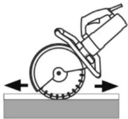
natural_image
Diagram of a cutting tool using a saw blade on a surface, showing motion direction (no text or symbols)
natural_image
Line drawing of a person's legs and feet interacting with a bicycle (no text or symbols)
| Ingen. | Beskrivelse |
| 1 | Skjede |
| 2 | Bryter |
| 3 | Brakett |
| 4 | Vanninntak |
| 5 | Beskyttende |
| 6 | Bladsag |
| 7 | Støvdemper |
| 8 | Håndtak |
| 9 Låsemutter for sagblad | |
| 10 | Hjul |
| 11 | Børstedeksel |
| 12 | Bakdeksel |
natural_image
Simple line drawing of a circle with diagonal lines and arrows, resting on a horizontal bar with supports (no text or symbols)
natural_image
Simple line drawing of a rectangular block with supports and an arrow indicating upward motion (no text or symbols)• Mat maskinen rett i linje med bladet. Sidetrykk kan skade bladet og er farlig.
VEDLIKEHOLDSANVISNING
| Ingen. | Beskrivelse | Antall | Ingen. | Beskrivelse | Antall | Ingen. | Beskrivelse | Antall |
| 1 | M8-mutter | 1 | 39 | Hodeskall | 1 | 71 | Vindskjerm | |
| 2 | Plastknott | 1 | 40 | 6301 lager | 1 | 72 | Stator | 1 |
| 3 | M8X35 skrue | 1 41 | Firkantnøkkel3X3X13.6 | 1 | 73 | 5X80 skrue | ||
| 4 | Beskyttende deksel | 1 | 42 | Spindel | 1 | 74 | 6201 lager | |
| 5 | 5X10 skrue | 2 | 43 | Firkantnøkkel4X4X13.6 | 1 | 75 | Motordeksel | 1 |
| 6 | Vanndyse | 1 | 44 | M5X20 skrue | 4 | 76 Festeklips | ||
| 7 | 4X10 skrue | 1 | 45 | 5 fjærskive | 4 | 77 | Børsteholder | 2 |
| 8 | 4 flat skive | 1 | 46 | 5 flat skive | 4 | 78 | Kullbørste | 2 |
| 9 | Støvutløpsdeksel | 1 | 47 | M6X35 skrue | 2 | 79 Spiralfjær | ||
| 10 | Støvdeksel | 1 | 48 | Rettvinklet feste | 1 | 80 Børstedeksel | ||
| 11 | 4X30 skrue | 1 | 49 | M6-mutter | 2 | 81 | 4X14 skrue | 6 |
| 12 | 4X10 skrue | 2 | 6 fjærskive | 2 | 82 | Forrett | 1 | |
| 13 | 4 flat skive | 2 | 6 flat skive | 2 | 83 | 4X14 skrue | 2 | |
| 14 | M8X1.25 mutter | 1 | 50 | M6X16 skrue | 2 | 84 Bakdeksel | 1 | |
| 15 | Lite utstyr | 1 | 6 fjærskive | 2 | 85 | 5X20 skrue | 4 | |
| 16 | 6200-lager | 1 | 6 flat skive | 2 | 86 | M6-mutter | 1 | |
| 17 | 14 akselklemme | 1 | 51 | M12X25 sekskantbolt | 1 | 87 | Bryterhåndtak (venstre) | 1 |
| 18 | Stort utstyr | 1 | 52 | 12 fjærskive | 1 | 88 | M5X25 skrue | 4 |
| 19 | Stort utstyr | 1 | 53 | 12 flat skive | 1 | 5 fjærskive | 4 | |
| 20 | Hodedeksel | 1 | 54 | M5X25 skrue | 4 | 5 flat skive | 4 | |
| 21 | 5X14 skrue | 4 | 5 fjærskive | 4 | 89 | Bryter | 1 | |
| 22 | 5 fjærskive | 4 | 5 flat skive | 4 | 90 | Skjede | 1 | |
| 23 | 5 flat skive | 4 | 55 | Armlenet | 1 | 91 | M6X25 skrue | |
| 24 | 6302 lager | 1 | 56 | Girkasse | 1 | 92 | Bryterhåndtak (høyre) | 1 |
| 25 | Liten drivaksel | 1 | 57 | Oljelede | 1 | 93 | 4X16 skrue | |
| 26 | Firkantnøkkel4X4X30 | 1 | 58 | 4X10 skrue | 4 | 94 Brakett | ||
| 27 | 6302 lagerpressing | 1 | 59 | Flatt gir | 1 | M8X45 sekskantbolt | 2 | |
| 28 | 5X14 skrue | 3 | 60 | Flat skive 23 X 15 X 1 | 1 | 96 | 8 flat skive | 1 |
| 29 | 5 fjærskive | 3 | 61 | 6200-lager | 1 | 97 | Hjul | 2 |
| 30 | 5 flat skive | 3 | 62 | Støvskjold | 1 | 98 | 8X8 avstandsstykke | 1 |
| 31 | Nedre trykkplate | 1 | 63 | M8X1.25 mutter | 1 | 99 M8-mutter | ||
| 32 | ∅vre trykkplate | 1 64 | Lite utstyr | 1 | 100 | 60X2 tetningsring | 1 | |
| 33 | Elastisk trykkplate | 1 | 65 | 4X10 skrue | 2 | 101 | 24X35X7 oljetetning | 1 |
| 34 | 10 flat skive | 1 | 66 | Lagerpressplate | 1 | 102 | 5X35 skrue | 4 |
| 35 | M10X25 skrue | 1 | 67 | 6202-lager | 1 | 103 | 4X8 skrue | 4 |
| 36 | Fest | 1 | 68 | 4X10 skrue | 1 | 104 | Kabel | 1 |
| 37 | Vår | 1 | 69 | Tilkoblingsdeksel | 1 | |||
| 38 | Låsering 6 | 1 | 70 | Rotor | 1 | |||


natural_image
Simple line drawing of a circle with diagonal lines and arrows, resting on a horizontal bar with supports (no text or symbols)
natural_image
Simple line drawing of a rectangular block with supports and an arrow indicating upward motion (no text or symbols)
natural_image
Simple line drawing of a circle crossed over a horizontal bar with triangular supports (no text or symbols)
natural_image
Simple line drawing of a beam with supports and an arrow indicating upward motion (no text or symbols)
natural_image
Simple line drawing of a circular object with diagonal lines and arrows, resting on a horizontal beam with supports (no text or symbols)
natural_image
Simple line drawing of a beam with supports and an arrow indicating upward motion (no text or symbols)| Nie. | Popis | Množstvo | Nie. | Popis | Množstvo | Nie. | Popis | Množstvo |
| 1 | Matica M8 | 1 | 39 | Hlavová škrupina | 1 | 71 | Veterný | štít |
| 2 | Plastový gombík | 1 | 40 | Ložisko 6301 | 1 | 72 | Stator 1 | |
| 3 | Skrutka M8X35 | 1 | 41 | Štvorcový klúč 3X3X13,6 | 1 | 73 | Skrutka | 5X80 |
| 4 | Ochranný kryt | 1 | 42 | Vreteno 1 | 74 | Ložisko | 6201 1 | |
| 5 | Skrutka 5X10 | 2 | 43 | Štvorcový klúč 4X4X13,6 | 1 | 75 | Kryt | motora |
| 6 | Vodná tryska | 1 | 44 | Skrutka M5X20 | 4 | 76 | Upevňovacia spona | 2 |
| 7 | Skrutka 4X10 | 1 | 45 | Pružinová podložka Φ 5 | 4 77 | Držiak na kefu | 2 | |
| 8 | Plochá podložka Φ 4 | 1 | 46 | Plochá podložka Φ 5 | 4 | 78 | Uhlíková | kefka |
| 9 | Kryt výfuku prachu | 1 | 47 | Skrutka M6X35 | 2 79 | Vinutá pružina | 2 | |
| 10 | Kryt proti prachu | 1 | 48 | Pravouhlý upevňovací prvok | 1 | 80 | Kryt | kefy |
| 11 | Skrutka 4X30 | 1 | 49 | Matica M6 | 2 81 | Skrutka | 4X14 6 | |
| 12 | Skrutka 4X10 | 2 | Pružinová podložka Φ 6 | 2 | 82 | Štartér | 1 | |
| 13 | Plochá podložka Φ 4 | 2 | Plochá podložka Φ 6 | 2 | 83 | Skrutka | 4X14 | |
| 14 | Matica M8X1,25 | 1 | 50 | Skrutka M6X16 | 2 84 | Zadný kryt | 1 | |
| 15 | Malý výstroj | 1 | Pružinová podložka Φ 6 | 2 | 85 | Skrutka | 5X20 | |
| 16 | Ložisko 6200 | 1 | Plochá podložka Φ 6 | 2 | 86 | Matica | M6 | |
| 17 | Svorka hriadeľa Φ 14 | 1 | 51 | Šesthranná skrutka M12X25 | 1 | 87 | Páka spínača (ľavá) | 1 |
| 18 rokov | Veľký výstroj | 1 | 52 | Pružinová podložka Φ 12 | 1 | 88 | Skrutka M5X25 | 4 |
| 19 | Veľký výstroj | 1 | 53 | Plochá podložka Φ 12 | 1 | Pružinová podložka Φ 5 | 4 | |
| 20 | Pokrývka hlavy | 1 | 54 | Skrutka M5X25 | 4 | Plochá podložka Φ 5 | 4 | |
| 21 | Skrutka 5X14 | 4 | Pružinová podložka Φ 5 | 4 | 89 | Prepínač | 1 | |
| 22 | Pružinová podložka Φ 5 | 4 | Plochá podložka Φ 5 | 4 | 90 | Plášť | 1 | |
| 23 | Plochá podložka Φ 5 | 4 | 55 | Lakťová opierka | 1 | 91 | Skrutka | M6X25 |
| 24 | Ložisko | 1 | 56 | Prevodovka | 1 | 92 | Páčka spínača | 1 |
| 6302 | (pravá) | |||||||
| 25 | Malý hnací hriadel' | 1 | 57 | Olejová prepážka | 1 | 93 | Skrutka | 4X16 |
| 26 | Štvorcový klúč 4X4X30 | 1 | 58 | Skrutka 4X10 | 4 | 94 | Zátvorka 1 | |
| 27 | 6302 lisovanie ložísk | 1 | 59 | Ploché ozubené koleso | 1 | 95 | Šesthranná skrutka M8X45 | 2 |
| 28 | Skrutka 5X14 | 3 | 60 | Plochá podložka Φ 23 X Φ 15 X 1 | 1 | 96 | Plochá podložka Φ 8 | 1 |
| 29 | Pružinová podložka Φ 5 | 3 | 61 | Ložisko 6200 | 1 | 97 | Koleso 2 | |
| 30 | Plochá podložka Φ 5 | 3 | 62 | Ochranný kryt proti prachu | 1 | 98 | Dištančná podložka Φ 8X8 | 1 |
| 31 | Spodná prítlačná doska | 1 | 63 | Matica M8X1,25 | 1 | 99 | Matica | M8 |
| 32 | Horná prítlačná doska | 1 | 64 | Malý výstroj | 1 | 100 | Tesniaci krúžok 60X2 | 1 |
| 33 | Elastická prítlačná doska | 1 | 65 | Skrutka 4X10 | 2 | 101 | Olejové tesnenie 24X35X7 | 1 |
| 34 | Plochá podložka Φ 10 | 1 | 66 | Prítlačná doska ložiska | 1 | 102 | Skrutka | 5X35 |
| 35 | Skrutka M10X25 | 1 | 67 | Ložisko 6202 1 | 103 | Skrutka 4X8 | 4 | |
| 36 | Pripnút | 1 | 68 | Skrutka 4X10 | 1 | 104 | Kábel | 1 |
| 37 | Jar | 1 | 69 | Pripojovací kryt | 1 | |||
| 38 | Poistný krúžok Φ 6 | 1 | 70 | Rotor | 1 |
5
2
4


natural_image
Simple line drawing of a circle crossed over a horizontal bar with triangular supports (no text or symbols)
natural_image
Simple line drawing of a beam with supports and an arrow indicating upward motion (no text or symbols)natural_image
Diagram of a cutting cutter with a crossed tool and gear, no text or symbols present
natural_image
Diagram of a cutting tool using a saw blade on a surface, showing motion direction (no text or symbols)
natural_image
Line drawing of a person's legs and feet interacting with a bicycle (no text or symbols)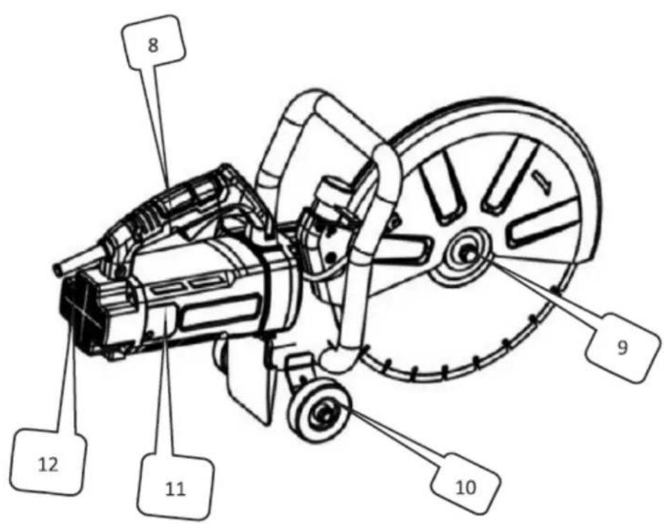
natural_image
Simple line drawing of a circular object with diagonal lines and arrows, resting on a horizontal beam (no text or symbols)
natural_image
Simple line drawing of a rectangular block with supports and an arrow indicating upward motion (no text or symbols)natural_image
Diagram of a cutting cutter with a crossed tool and gear, no text or symbols present
natural_image
Diagram of a cutting tool using a saw blade on a workpiece, showing motion direction (no text or symbols)
natural_image
Line drawing of a person's lower body and foot wearing a bicycle (no text or symbols)
| Ne. | Opis |
| 1 | Omotač |
| 2 | Prekidač |
| 3 | Zagrada |
| 4 | Dovod | vode |
| 5 | Zaštitni | poklopac |
| 6 Pila za rezanje | ||
| 7 | Prigušivač prašine | |
| 8 | Ručka | |
| 9 Matica za blokiranje lista pile | ||
| 10 | Kotač | |
| 11 | Poklopac | četke |
| 12 | Stražnji | poklopac |
3.2. Priprema za upotrebu
PRETHODNA PROVJERA
1. Izvor napajanja
natural_image
Simple line drawing of a circle crossed over a horizontal bar with triangular supports (no text or symbols)
natural_image
Simple line drawing of a beam with supports and an arrow indicating upward motion (no text or symbols)• Stroj pomičite ravno u liniji s oštricom. Bočni pritisak može oštetiti oštricu i opasan je.
3.5. Čišćenje i održavanje
| Ne. | Opis | Količina | Ne. | Opis | Količina | Ne. | Opis | Količina |
| 1 | Matica M8 | 139 | Školjka za glavu 1 | 71 | Vjetrobran 1 | |||
| 2 | Plastična ručka | 1 | 40 | Ležaj 6301 | 1 | 72 | Stator 1 | |
| 3 | Vijak M8X35 | 41 | Kvadratni ključ 3X3X13.6 | 1 | 73 | Vijak 5X80 | ||
| 4 | Zaštitni poklopac | 1 | 42 | Vreteno | 1 | 74 | Ležaj 6201 | 1 |
| 5 | Vijak 5X10 | 2 | Kvadratni ključ 4X4X13.6 | 1 | 75 | Poklopac | motora | |
| 6 | Mlaznica za vodu | 1 | 44 | Vijak M5X20 | 4 | 76 | Kopča za pričvršćivanje | 2 |
| 7 | Vijak 4X10 | 1 | 45 | Opružna podložna pločica Φ 5 | 4 | 77 | Držač za četke | |
| 8 | Ravna podloška Φ 4 | 1 | 46 | Ravna podloška Φ 5 | 4 | 78 | Karbonska četkica | 2 |
| 9 | Poklopac za odvod prašine | 1 | 47 | Vijak M6X35 | 2 | 79 | Spiralna opruga | 2 |
| 10 | Poklopac za prašinu | 1 | 48 | Pričvršćivač pod pravim kutom | 1 | 80 | Poklopac | četke |
| 11 | Vijak 4X30 | 1 | 49 | Matica M6 | 2 | 81 | Vijak 4X14 | 6 |
| 12 | Vijak 4X10 | 2 | Opružna podložna pločica Φ 6 | 2 | 82 | Starter | 1 | |
| 13 | Ravna podloška Φ 4 | 2 | Ravna podloška Φ 6 | 2 | 83 | Vijak 4X14 | ||
| 14 | Matica M8X1.25 | 1 | 50 | Vijak M6X16 | 2 | 84 | Stražnji poklopac | 1 |
| 15 | Mala oprema | 1 | Opružna podložna pločica Φ 6 | 2 | 85 | Vijak 5X20 | ||
| 16 | Ležaj 6200 | 1 | Ravna podloška Φ 6 | 2 | 86 | Matica M6 | ||
| 17 | Stezaljka osovine Φ 14 | 1 | 51 | Šesterokutni vijak M12X25 | 1 | 87 | Ručica prekidača (lijevo) | 1 |
| 18 godina | Velika oprema | 1 | 52 | Opružna podložna pločica Φ 12 | 1 | 88 | Vijak M5X25 | 4 |
| 19 | Velika oprema | 1 | 53 | Ravna podloška Φ 12 | 1 | Opružna podložna pločica Φ 5 | 4 | |
| 20 | Pokrivalo za glavu | 1 | 54 | Vijak M5X25 | 4 | Ravna podloška Φ 5 | 4 | |
| 21 | Vijak 5X14 | 4 | Opružna podložna pločica Φ 5 | 4 | 89 | Prekidač | 1 | |
| 22 | Opružna podložna pločica Φ 5 | 4 | Ravna podloška Φ 5 | 4 | 90 | Omotač | 1 | |
| 23 | Ravna podloška Φ 5 | 4 | 55 | Naslon za ruke | 1 | 91 | Vijak M6X25 | 1 |
| 24 | Ležaj 6302 | 1 | 56 | Mjenjač | 1 | 92 | Ručica prekidača (desna) | 1 |
| 25 | Malo pogonsko | 1 | 57 | Pregrada za ulje | 1 | 93 | Vijak 4X16 | 5 |
| vratilo | ||||||||
| 26 | Kvadratni ključ 4X4X30 | 1 | 58 | Vijak 4X10 | 4 94 | Zagrada 1 | ||
| 27 | 6302 prešanje ležaja | 1 | 59 | Plosnati zupčanik | 1 | 95 | Šesterokutni vijak M8X45 | 2 |
| 28 | Vijak 5X14 | 3 | 60 | Ravna podloška 23 X 15 X 1 | 1 | 96 | Ravna podloška 8 | 1 |
| 29 | Opružna podložna pločica 5 | 3 | 61 | Ležaj 6200 | 1 97 | Kotač | 2 | |
| 30 | Ravna podloška 5 | 3 | 62 | Štitnik od prašine | 1 | 98 | Odstojnik | 8X8 1 |
| 31 | Donja ploča za pritiskanje | 1 | 63 | Matica M8X1.25 1 99 | Matica M8 2 | |||
| 32 | Gornja ploča za pritiskanje | 1 | 64 | Mala oprema | 1 | 100 | Brtveni prsten 60X2 | 1 |
| 33 | Elastična ploča za pritiskanje | 1 | 65 | Vijak 4X10 | 2 101 | Uljna brtva 24X35X7 | 1 | |
| 34 | Ravna podloška 10 | 1 | 66 | Ploča za pritiskanje ležaja | 1 | 102 | Vijak 5X35 | 4 |
| 35 | Vijak M10X25 | 1 | 67 | Ležaj 6202 | 1 103 | Vijak 4X8 | 4 | |
| 36 | Prikvači | 1 | 68 | Vijak 4X10 | 1 | 104 | Kabel | 1 |
| 37 | Proljeće | 1 | 69 | Poklopac za spajanje | 1 | |||
| 38 | Oscilatorni prsten 6 | 1 | 70 | Rotor | 1 | |||


| Nr. | Aprašymas |
| 1 | Apvalkalas |
| 2 | Jungiklis |
| 3 | Laikiklis |
natural_image
Simple line drawing of a circle crossed over a horizontal bar with triangular supports (no text or symbols)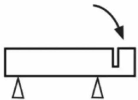
natural_image
Simple line drawing of a beam with supports and an arrow indicating upward motion (no text or symbols)
natural_image
Simple line drawing of a circle with diagonal lines and arrows, above a horizontal bar with triangular supports (no text or symbols)
natural_image
Simple line drawing of a beam with supports and an arrow indicating upward motion (no text or symbols)natural_image
Diagram of a cutting tool crossed over a gear with an arrow indicating direction (no text or symbols)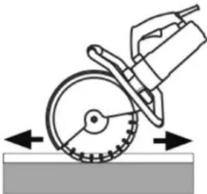
natural_image
Diagram of a cutting cutter tool operating on a workpiece with directional arrows indicating motion (no text or symbols)
natural_image
Line drawing of a person's lower body and foot, showing mechanical components (no text or symbols)
natural_image
Simple line drawing of a circle crossed over a horizontal bar with triangular supports (no text or symbols)
natural_image
Simple line drawing of a beam with supports and an arrow indicating upward motion (no text or symbols)- Pri zagonu stroja se prepričajte, da rezilo ni v stiku z nobenim predmetom.
| Ne. | Opis | Količina | Ne. | Opis | Količina | Ne. | Opis | Količina |
For the disposal of the device please consider and act according to the national and local rules and regulations.
CONTACT
expondo Polska sp. z o.o. sp. k.