WOOHS-E3600K - Electric saw MSW - Free user manual and instructions
Find the device manual for free WOOHS-E3600K MSW in PDF.

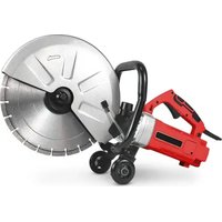
| Product type | Horizontal band saw |
| Brand | MSW |
| Model | WOOHS-E3600K |
| Rated power | 2600 W |
| Rated voltage / Frequency | 230 V~ / 50 Hz |
| Motor speed | 2800 rpm |
| Protection class | IP44 |
| Blade speed | 14 m/s |
| Maximum cutting capacity | 457 mm |
| Dimensions (L x W x H) | 1350 x 1240 x 3000 mm |
| Weight | 152 kg |
| Intended use | Sawing logs on a firm, level surface |
| Power supply | Electric, single-phase 230 V |
| Cutting materials | Wood only (no metal, nails, etc.) |
| Safety devices | Blade guard, wheel guard, safety switch, locking handles |
| Regular maintenance | Cleaning sawdust, lubricating guides, belt and blade tension, bearing inspection |
| Repairability | Spare parts available: blades, belts, bearings, guides |
| Included accessories | Guide rails, log supports, lubrication tank, mounting wrenches |
Frequently Asked Questions - WOOHS-E3600K MSW
User questions about WOOHS-E3600K MSW
0 question about this device. Answer the ones you know or ask your own.
Ask a new question about this device
Download the instructions for your Electric saw in PDF format for free! Find your manual WOOHS-E3600K - MSW and take your electronic device back in hand. On this page are published all the documents necessary for the use of your device. WOOHS-E3600K by MSW.
USER MANUAL WOOHS-E3600K MSW
natural_image
Metal ladder structure with multiple horizontal ladders and mounting feet (no text or symbols visible)
natural_image
Close-up of two metal structural components with bolts and a metallic bracket (no text or symbols visible)natural_image
Close-up of a metallic mechanical assembly with bolts and a base, no visible text or symbolsnatural_image
Two metallic mechanical tools or clamps shown from different angles (top and side), no text or symbols visible.natural_image
Close-up of a metal ladder with attached clamps and a horizontal bar, showing red directional arrows (no text or symbols)natural_image
Person wearing gloves and blue gloves operating a metal rail bridge with two wheels (no text or symbols visible)natural_image
Close-up of a green metal frame with a red line and green arrow pointing to a wooden post (no text or symbols visible)
natural_image
Close-up of a hand using a tool to lift a green surface, with no visible text or symbols.natural_image
Person installing or maintaining a green metal frame structure on a grassy field, with red arrows indicating movement directions (no text or symbols visible)natural_image
Mechanical testing setup with black and red components mounted on a blue base, placed on white fabric (no visible text or symbols)A - Blattspannung

A - Kettenmutter
B - Stahlseil
C - Stahlseil
D - Hebegriff
natural_image
Industrial robotic device with blue frame and black frame, displayed indoors (no visible text or symbols)natural_image
Close-up of hands operating a mechanical assembly with metal brackets and bolts (no visible text or symbols)
natural_image
White cylindrical container labeled 'A' being handled by a black-and-white mechanical device (no visible text or symbols on the container itself)

natural_image
Close-up of a mechanical device with a ruler and clamped components (no visible text or symbols)natural_image
Industrial machine with blue frame structure and labeled components A and B, no readable text or symbols beyond labelsnatural_image
Close-up of a red industrial machine with black pulley and belt (no visible text or symbols)natural_image
Close-up of a mechanical assembly with two circular annotations highlighting features (no visible text or symbols)
natural_image
Industrial machinery with two large circular wheels mounted on a platform, no visible text or symbols
natural_image
Close-up of a mechanical assembly with red arrows indicating direction or force, no visible text or symbolsnatural_image
Person cleaning a red industrial fan with a tool, showing the blade being cut (no text or symbols visible)natural_image
Industrial machine with white frame and black components, red background (no visible text or symbols)natural_image
Close-up of a red industrial wheel with three circular arrows indicating rotational flow (no text or symbols)
natural_image
Close-up of a red industrial wheel with three circular arrows indicating rotational flow (no text or symbols)
natural_image
Three-panel mechanical assembly diagram showing pipe connection and red directional arrows (no text or symbols)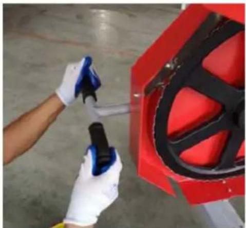
natural_image
Person cleaning a red industrial component with a tool, no visible text or symbolsnatural_image
Industrial machine with white frame and black components, red background (no visible text or symbols)natural_image
Close-up of a mechanical component with a red circle highlighting a specific area (no visible text or symbols)natural_image
Close-up of a dark, textured object with a rectangular cutout and a small rectangular block inside (no visible text or symbols)natural_image
Close-up of a red and black tire roller with yellow and blue guide bars, no visible text or symbolsnatural_image
Industrial machinery with two large pulleys and connecting rods, no visible text or symbolsnatural_image
Two industrial machinery components: a red pipe joint and a blue-capped clamp, both with red arrows indicating bidirectional movement (no text or symbols visible)natural_image
Three-panel image showing a red industrial machine being adjusted, with toolbars and a close-up of the process (no visible text or symbols)natural_image
Close-up of a mechanical assembly with two circular annotations highlighting features (no readable text or symbols)
natural_image
Close-up of a mechanical assembly with a bolted spring and two curved arrows indicating rotational motion (no text or symbols present)This User Manual has been translated for your convenience using machine translation. Reasonable efforts have been made to provide an accurate translation; however, no automated translation is perfect nor is it intended to replace human translators. The official User Manual is the English version. Any discrepancies or differences created in the translation are not binding and have no legal effect for compliance or enforcement purposes. If any questions arise related to the accuracy of the information contained in the User Manual, please refer to the English version of those contents which is the official version.
Technical data
| Parameter description Parameter value | |
| Product name | Horizontal Band Saw |
| Model | MSW-WOOHS-7HP |
| Engine Power [kW] | 4.1 |
| Engine Speed [rpm] | 3600 |
| Blade Speed [m/s] | 14 |
| Max Cutting Capacity [mm] | 457 |
| Dimensions [width x depth x height; mm] | 1250 x 1340 x 3000 |
| Weight [kg] | 156 |
| Parameter description Parameter value | |
| Product name | Horizontal Band Saw |
| Model | MSW-WOOHS-E3600K |
| Rated voltage [V~] / frequency [Hz] | 230/50 |
| Rated power [W] | 2600 |
| Motor Speed [rpm] | 2800 |
| Protection rating IP | IP44 |
| Blade Speed [m/s] | 14 |
| Max Cutting Capacity [mm] | 457 |
| Dimensions [width x depth x height; mm] | 1350 x 1240 x 3000 |
| Weight [kg] | 152 |

WARNING:
Read carefully and understand all INSTRUCTIONS before operating. Failure to follow the safety rules and other basic safety precautions may result in serious personal injury.
FOREWORD
This machine is designed for certain applications only. We strongly recommend this machine is not modified and/or used for any application other than that for which it was designed. If you have any questions relative to a particular application, DO NOT use the machine until you have first contacted us to determine if it can or should be performed on the product.
INTENDED USE
This sawmill is designed for sawing logs while the mill is firmly supported on the ground.
GENERAL SAFETY RULES

WARNING: Read and understand all instructions. Failure to follow all instructions listed below may result in electric shock, fire and/or serious injury.

WARNING: The warnings, cautions, and instructions discussed in this instruction manual at cover all possible conditions or situations that could occur. It must be understood by the tor that common sense and caution are factors which cannot be built into this product, but be supplied by the operator.
WORK AREA
- Keep work area clean, free of clutter and well lit. Cluttered and dark work areas can cause accidents.
- Do not use your sawmill where there is a risk of causing a fire or an explosion; e.g. In the presence of flammable liquids, gasses, or dust. Power tools create sparks, which may ignite the dust or fumes.
- Keep children and bystanders away while operating a power tool. Distractions can cause you to lose control, so visitors should remain at a safe distance from the work area.
- Be aware of all power lines, electrical circuits, water pipes and other mechanical hazards in your work area, particularly those hazards below the work surface hidden from the operator's view that may be unintentionally contacted and may cause personal harm or property damage.
- Be alert of your surroundings. Using power tools in confined work area may put you dangerously close to cutting tools and rotating parts.
PERSONAL SAFETY
- Stay alert, watch what you are doing and use common sense when operating a power tool. Do not use a power tool while you are tired or under the influence of drugs, alcohol or medication. A moment of inattention while operating power tools may result in serious personal injury.
- Dress properly. Do not wear loose clothing, dangling objects, or jewellery. Keep your hair, clothing and gloves away from moving parts. Loose clothes, jewellery or long hair can be caught in moving parts. Air vents often cover moving parts and should be avoided.
- Use safety apparel and equipment. Use safety goggles or safety glasses with side shields which comply with current national standards, or when needed, a face shield.
- Use as dust mask in dusty work conditions. This applies to all persons in the work area. Also use non-skid safety shoes, hardhat, gloves, dust collection systems, and hearing protection when appropriate.
- Do not over reach. Keep proper footing and balance at all times.
- Remove adjusting keys or wrenches before connecting to the power supply or turning on the tool. A wrench or key that is left attached to a rotating part of the tool may result in personal injury.
- Never make blade guide adjustments, remove or install blades or conduct any other maintenance or make any other adjustments when the engine is running.
TOOL USE AND CARE
- Always be sure operator is familiar with proper safety precautions and operation techniques before using machine.
- Avoid "kick-back" by knowing what conditions can create it.
- Do not force the tool. Tools do a better and safer job when used in the manner for which they are designed.
-
Never use the sawmill with a malfunctioning switch. Any power tool that cannot be controlled with the switch is dangerous and must be repaired before using.
-
Turn off the engine and place the switch in the locked or off position before servicing, adjusting, installing accessories or attachments, or storing. Such preventive safety measures reduce the risk of starting the power tool accidentally.
- Secure logs with the log screw clamping device instead of with your hand or another individual's help. This safety precaution allows for proper tool operation using both hands.
- Storing sawmill. When the sawmill is not use, store it in a dry, secure place or keep well covered and out of the reach of children. Inspect the sawmill for good working condition prior to storage and before re-use.
- Maintain your sawmill. It is recommended that the general condition of the sawmill be examined before it is used. Keep your sawmill in good repair by adopting a program of conscientious repair and maintenance in accordance with the recommended procedures found in this manual. If any abnormal vibrations or noise occurs, turn the sawmill off immediately and have the problem corrected before further use.
- Keep saw blades sharp and clean. Properly maintained band saw blades are less likely to bind and are easier to control.
- Cleaning and Lubrication. Use only soap and a damp cloth to clean your sawmill.
Many household cleaners are harmful to plastic and rubber components on the sawmill.
- Use only accessories that are recommended by the manufacturer for your model.
Accessories that may be suitable for another sawmill may create a risk of injury when used on the sawmill. - Always operate machine with all safety devices and guards in place and in working order. DO NOT modify or make changes to safety devices. DO NOT operate machine if any safety devices or guards are missing or inoperative.
• Never leave sawmill running unattended. - Coiled blades can spring apart with considerable force and unpredictably in any direction. Always deal with coiled blades, including those packaged in boxes, with the utmost care.
- Never use the equipment to cut anything other than lumber or for any purpose other than cutting lumber as described in this manual.
START UP PROCEDURE – EQUIPMENT OPERATION
- Wear heavy-duty work gloves, ANSI-approved goggles behind a full-face shield, steel-toed work boots, and a dust mask.
- Operate only with assistance.
- Ensure guide blocks are tight and track is level.
- Fill the lubrication tank with clean water and washing up detergent.
- Start and operate the engine.
- Cut branches off the lumber to be processed.
- WARNING: To avoid death or serious injury, Do not cut lumber with foreign objects in it such as nails, any metal pieces, etc.
- Place the lumber to be cut on the supports.
- WARNING: The operator and any assistants must stay clear of the front and back of the blade whenever the engine is ON.
- Move the saw head slowly along the track and against the lumber to make the cut.
- Trim off the rounded sides of the log.
- When the log is squared-off, boards or posts can be cut to custom specifications.
GENERAL MAINTENANCE INFORMATION
Proper and routine maintenance is critical to operator safety, achieving good milling results and to prolonging the life of your investment.
- Band Wheel Bearing --- Should be inspected before use to ensure they are not worn. Bearings are sealed and do not need to be greased.
- Blade Guide Bearing --- Inspect before use for excessive grooves or scoring in the bearing case. Replace if necessary.
- Blade Tension --- Grease threads of tensioning "T" handle when dry or as required. Use multi-purpose, extreme-pressure grease.
- Log Screws --- Grease frequently.
- Belts --- Periodically check the condition and wear of the drive and idler belt. Ensure that the blade does not ride on the band wheels.
- Drive Belt --- Periodically check the tension of the drive belt. It should deflect by no more than 1/2" (12.5 mm).
- Saw head Locking Cam Handles --- Grease assembly every 30 days or as required.
- Saw head Vertical Posts --- Spray posts before use with a silicone spray lubrication such as 3-in-1 or Jig-A-Loo.
- Band wheel Guards --- Routinely remove any build-up of sawdust that may collect inside the band wheel guards.
- Lubrication Tank --- Only fill with a water/washing up detergent mixture (one to two caps) or in winter months, use windshield washer fluid. Do not leave lubricant in tank if temperatures fall below 0^ C.
- Blade Lubricant --- Never use diesel fuel or kerosene as blade lubricant. These substances lead to premature wear of your belts and poor sawing performance. For winter operations, replace the water lubricant with windshield washer fluid.
- Saw head Lifting Cables --- Regularly before, during and after operations, inspect the cables for any wear or kinks. Ensure that the cables are in perfect condition. Oil coiled part of cable often to prevent premature wear. Replace with new cables as necessary.
SAWMILL ASSEMBLY
PARTS INSPECTION
A. Take all of the parts out of the shipping crate and lay them out.
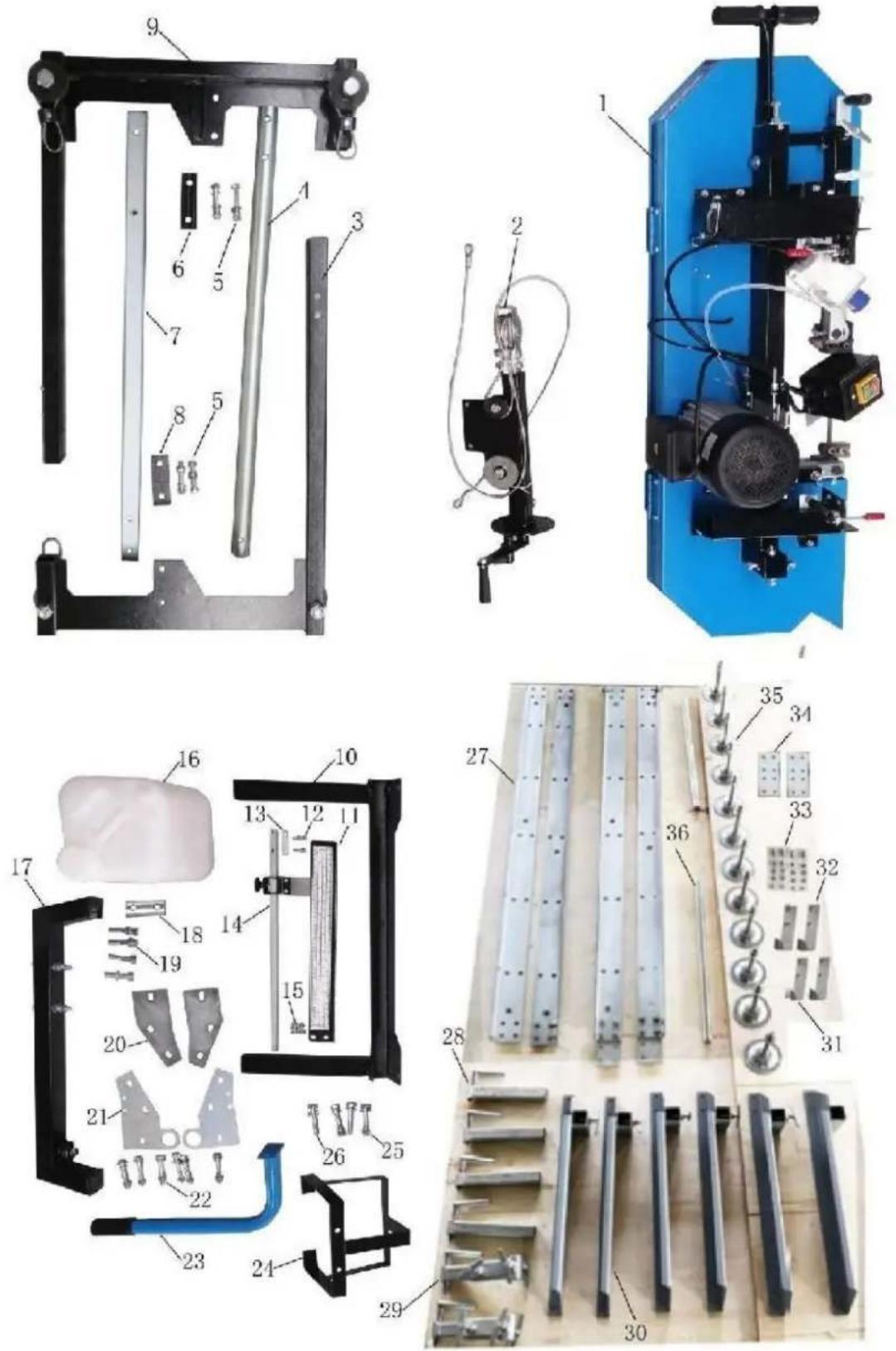
B. Check all the parts in according to blow parts list.
| NO. | DESCRIPTION | Qty. | NO. | DESCRIPTION | Qty. |
| 1 | SAW HEAD | 1 | 19 | HEX BOLT M10X55WASHER 10mmSPRING WASHER 10mm | 444 |
| 2 | STEEL ROPE HOLDER COMPLETE | 1 | 20 | JOINT PLATE B | 2 |
| 3 | LEFT VERTICAL FRAME | 1 | 21 | JOINT PLATE A | 2 |
| 4 | ROUND SUPPORT | 1 | 22 | HEX BOLT M10X70WASHER 10mmSPRING WASHER10mmHEX BOLT M10 | 61266 |
| 5 | HEX BOLT M12X70WASHER 12mmSPRING WASHER 12mmHEX NUT M12 | 4444 | 23 | PUSH-PULL HANDLE | 1 |
| 6 | SPACER PLATE C | 1 | 24 | SUPPORT POST FOR TANK | 1 |
| 7 | SQUARE POST | 1 | 25 | HEX BOLT M10X65WASHER 10mmSPRING WASHER10mmHEX NUT M10 | 2422 |
| 8 | SPACER PLATE B | 1 | 26 | HEX BOLT M10X65WASHER 10mmSPRING WASHER 10mm | 222 |
| 9 | RIGHT VERTICAL FRAME | 1 | 27 | GUIDE RAIL | 4 |
| 10 | STRENGTHEN BRACKET | 1 | 28 | FIXED CLAMP ASM | 4 |
| 11 | SCALE BRACKET(WITH SCALE) | 1 | 29 | MOVABLE CLAMP ASM | 2 |
| 12 | HEX BOLT M6X25WASHER 6mm | 22 | 30 | CROSS ARM ASM | 6 |
| 13 | SPACER BLOCK | 1 | 31 | STOPPER NO.1 | 2 |
| 14 | POINTER COMPLETE | 1 | 32 | STOPPER NO.2 | 2 |
| 15 | HEX BOLT M8X16WASHER 8mmHEX NUT M8 | 222 | 33 | HEX BOLTM10X25 HEXNUT M10 HEXBOLT M12X25WASHER 12mm | 484844 |
| 16 | COOLANTTANKWITH PLASTIC TUBE | 1 | 34 | JOINT PLATE | 2 |
| 17 | JOINT BRACKET WITH BOLTS | 1 | 35 | FOOT PAD WITH NUT & WASHER | 12 |
| 18 | SPACER PLATE A | 1 | 36 | SLIDING BAR | 2 |
TRACKS ASSEMBLY
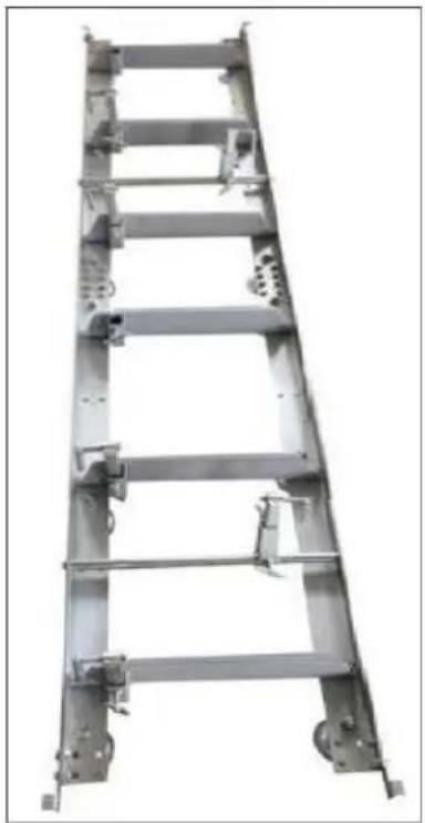
Assemble track system and secure loosely with provided nuts & bolts. It is important not to fully tighten the bolts at this stage. This will be done after the head is assembled and rolled along the track. It is ideal to assemble the tracks on a solid and level footing that is a minimum of 4" off the ground – We recommend you attach the levelling legs to sleepers which we discuss later in the instruction manual. This will allow for easy cleanup of sawdust from under the tracks and height adjustment of the log supports and also easier levelling of the track.
natural_image
Metal ladder structure with attached components, no visible text or symbols
natural_image
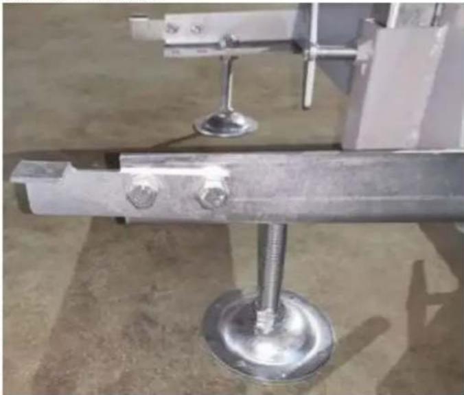
Close-up of metallic structural components with bolt holes and a metal frame (no text or symbols visible)Attach track cross supports to "L" channel with the provided nuts & bolts. The joining plate is used at the seam joint to join the two sections together (shown in top right image). Ensure to only hand tighten at this stage. The bolts will be fully tightened once the head assembly is free to roll on the tracks and provide the correct track width.
natural_image
Close-up of a metallic mechanical assembly with bolts and a circular base (no visible text or symbols)Assemble carriage stops at the ends of the tracks (4 stops total) and tighten.
LOG DOG & SUPPORTS
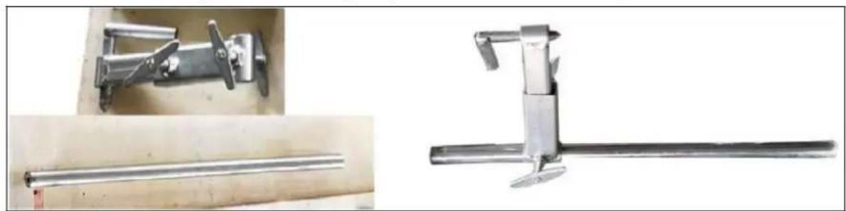
Assemble log dog pieces as shown below and use water proof grease on threaded handle and "T" handle. Attach assembly to the track using the provided nuts & bolts and tighten.
natural_image
Two metallic mechanical tools with lever mechanisms, shown from different angles (no text or symbols visible)Attach log dog assembly to track as shown below with 2 bolts and washers provided. Note that there are various locations along the track where this assembly can be bolted. Depending on how many track sections are being used, select a log clamp position that will secure the log firmly against the log supports.
natural_image
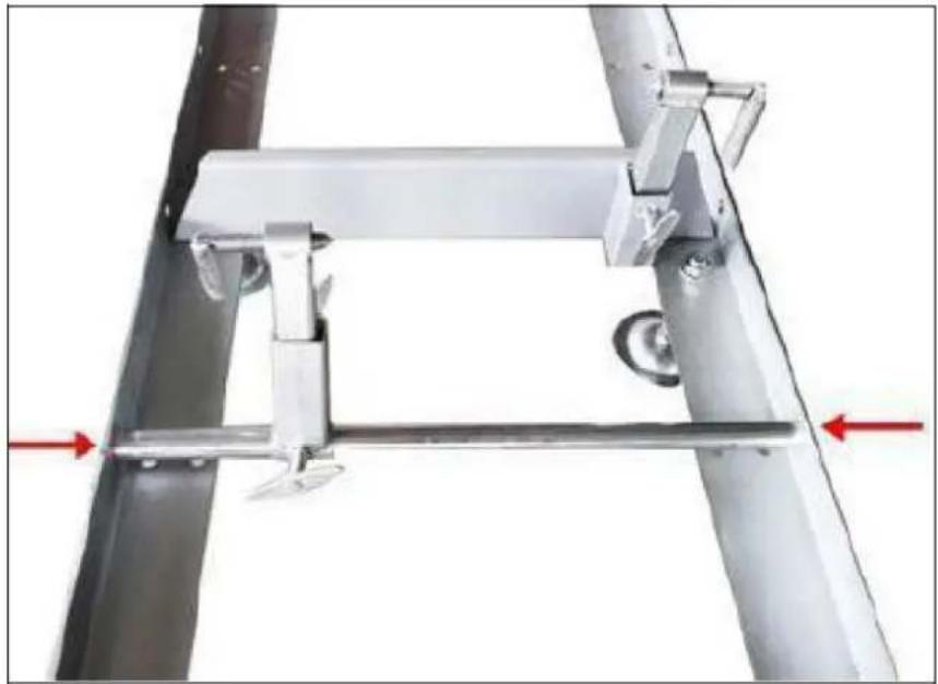
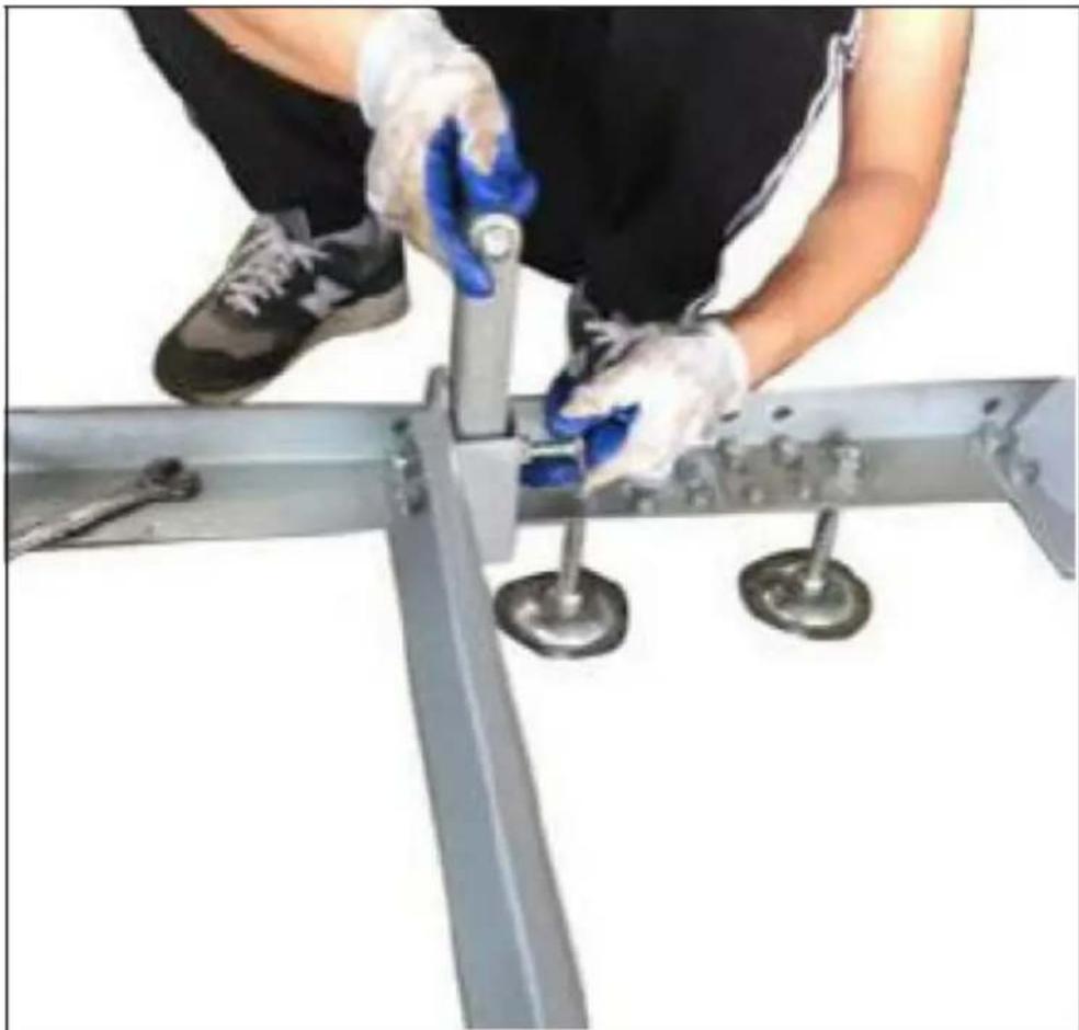
Mechanical assembly with metal frame and adjustment lever, no visible text or symbolsInsert log supports into track cross supports and secure with "T" handles. The "T" handle thread should be coated with waterproof grease.
natural_image
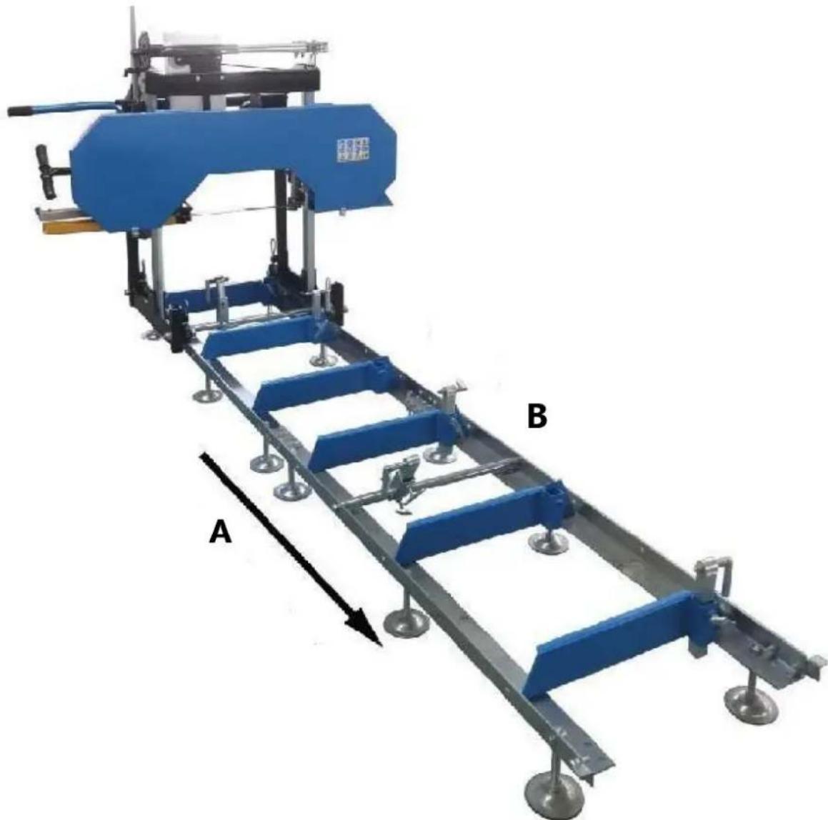
Person wearing gloves and blue gloves operating a metal rail bridge with two wheels (no text or symbols visible)Make the cross arm on the tracks at same level
Note:
If the ground is not hard floor and not level, you can insert some wood blocks under the track.
natural_image
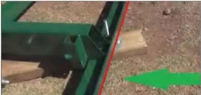
Close-up of a green metal frame structure with wooden supports and a red diagonal line, set on dry grass (no text or symbols visible)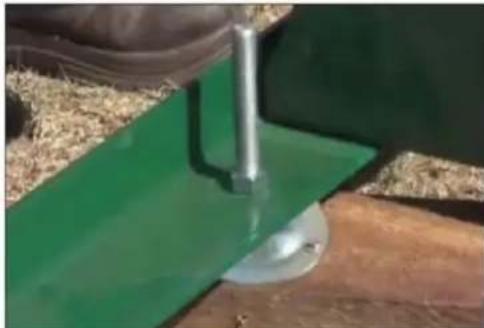
natural_image
Close-up of a green mechanical component with a metal lever, mounted on a wooden surface (no visible text or symbols)We recommend screwing the levelling legs onto the sleepers after the mill has been levelled. Therefore, before screwing the mill to the sleepers, it is recommended to run a string line on both sides of the mill to ensure that the track is straight and level.
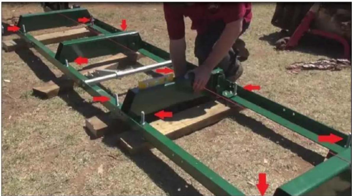
The red arrows indicate the locations of the levelling legs are. There are six per 1.5 metres of track, 12 in total on the machine. On the intermediate bunks the levelling legs alternate. We recommend placing the mill levelling legs on sleepers running left to right as shown above. You need to make sure the bunks are also level. To do this you use a spirit level going left to right on top of each bunk and also using a string line down the length of the track. The string line needs to be approx. 10mm above the bunks.
natural_image
Person operating a green metal frame structure on a grassy field, with red arrows indicating movement or force directions (no text or symbols visible)Carriage assembly
Place a moving blanket on the shipping pallet that the sawmill crate was strapped to. The blanket will prevent the blade guard covers from becoming scratched. Using a minimum of two people or a mechanical advantage system, remove the head assembly from the sawmill crate and place face down on the blanket. The head assembly is very heavy, proper technique must be used to avoid injury or damage.
natural_image
Mechanical testing setup with blue base, black components, and labeled component A (no readable text or symbols)A - Blade tension
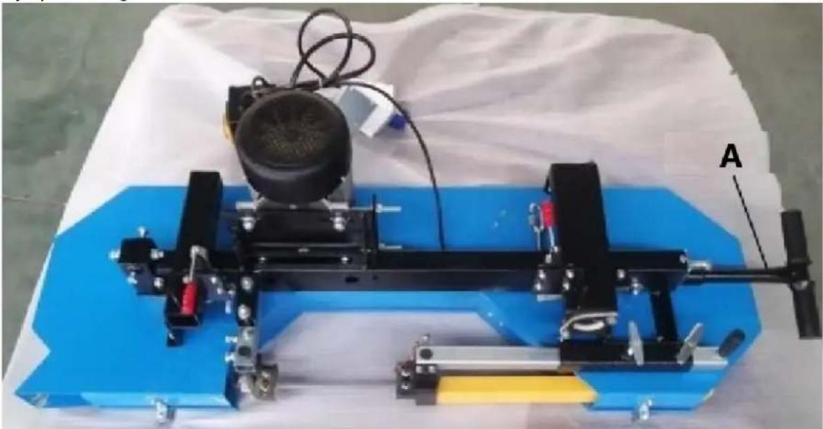
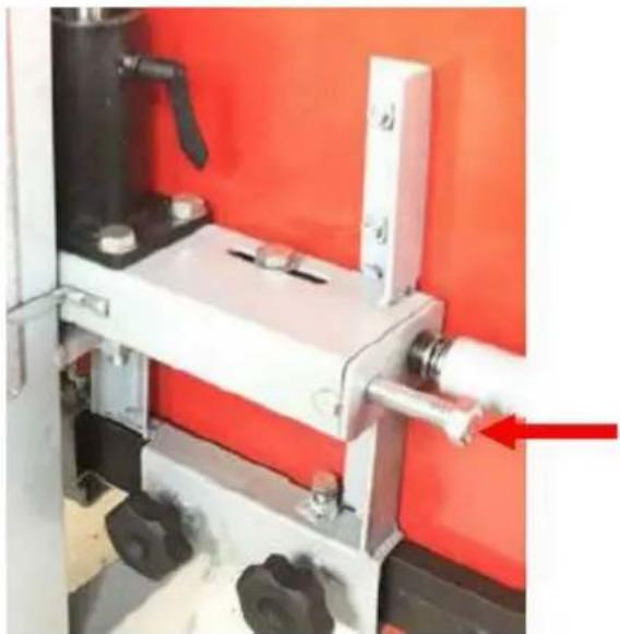
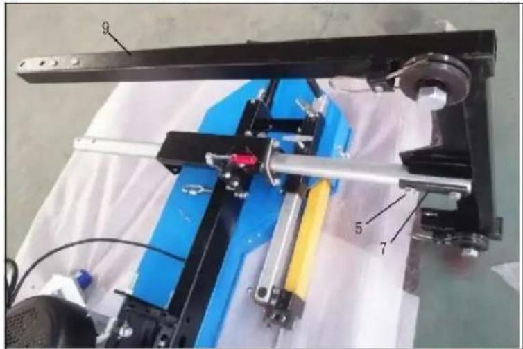
Find the square and round columns, and insert the round one into the sliding tube close to blade tension system, and insert square one into the sliding tube on the other side, and fix two vertical post by the locking handle. Attention to the stop bolt on the square column.
A – Sliding tube
B – Locking handle
C-Round column
D-Square column
E - Sliding tube
F - Stop bolt
Connect the Left vertical frame (3) to the Square column as shown by bolts (5) and Space plate B (8). And then connect the Right vertical frame (9) to the Round column by bolts (5) and Space plate C (6).
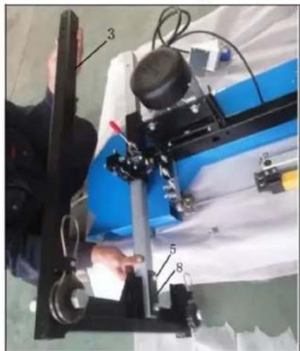
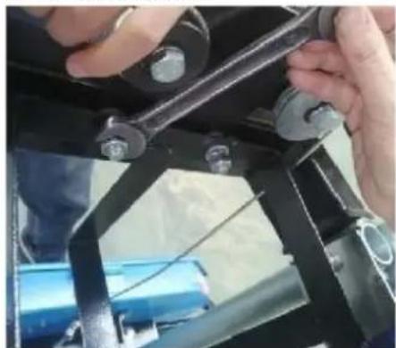
Connect the Joint bracket (17) to the Square column and Round column by bolts (19) and Space plate A (18). Loosen the bolts and nuts on the Joint bracket, and fix the Steel rope holder as picture showing.
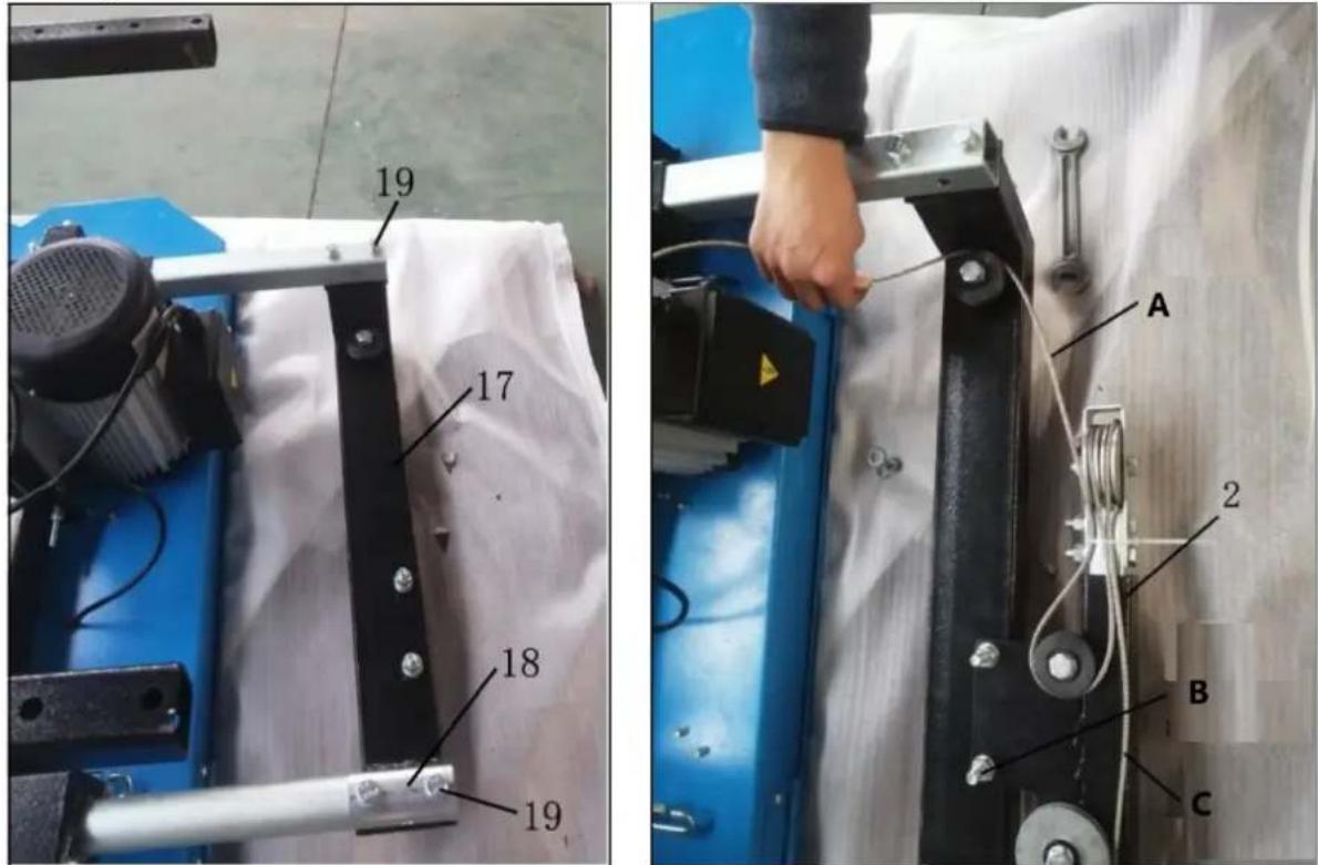
A – Rope -1 B – Bolts and nuts C – Rope-2
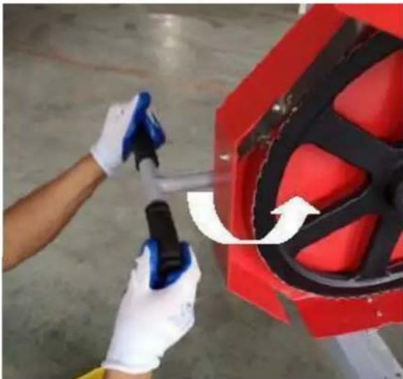
Loosen the Chain nut on machine head, Let the Steel rope across the pulley, fix two ends of Steel rope to the holders, tighten the Chain nut. Swing the Lift handle to make the steel rope tighten. Lock the Locking handles.
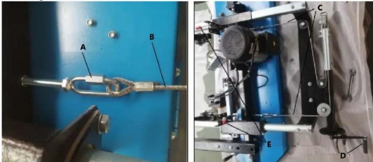
A – Chain nut B – Steel rope C – Steel rope D – Lift handle
E-Locking handle
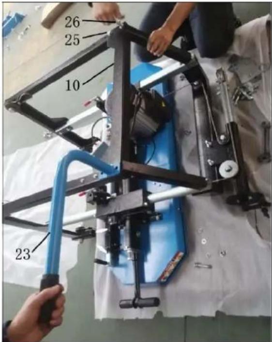
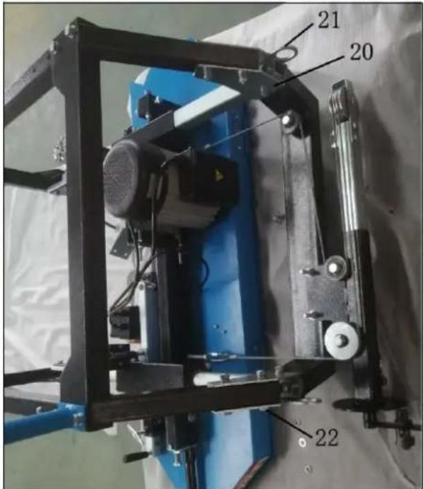
Connect the Strengthen bracket (10) and Push-pull handle (23) by parts supplied (25, 26, 20, 21, 22).
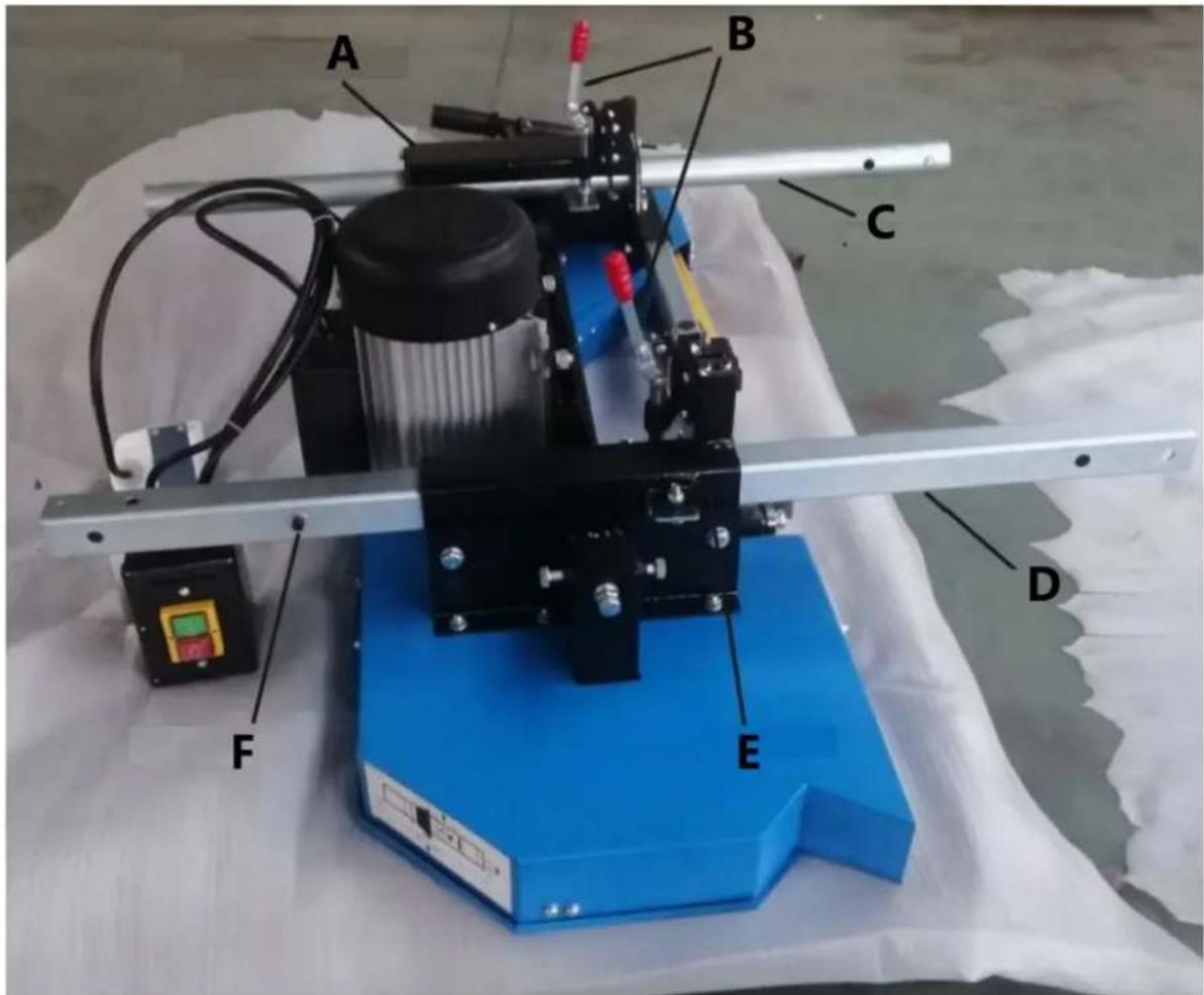
Loosen two Pan head screws and install the Power switch on the Right vertical frame. Loosen two Pan head screws on the Left vertical frame and fix the Plug.
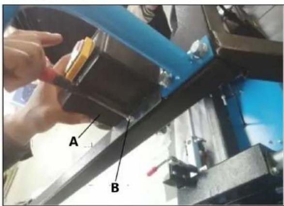
A - Power switch
B, C - Pan head screw
D - Plug.
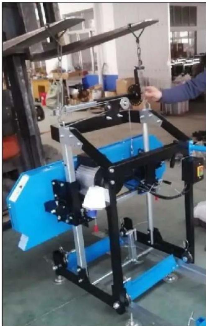
After carriage assembly on pallet, lift the machine carriage by forklift to make it stand up and put it onto the track system, ensure the grooves of four wheels well fit the rails of track and move smoothly on the track. If no forklift at working area, at least two peoples are necessary to make the machine carriage stand up and put it on the track.
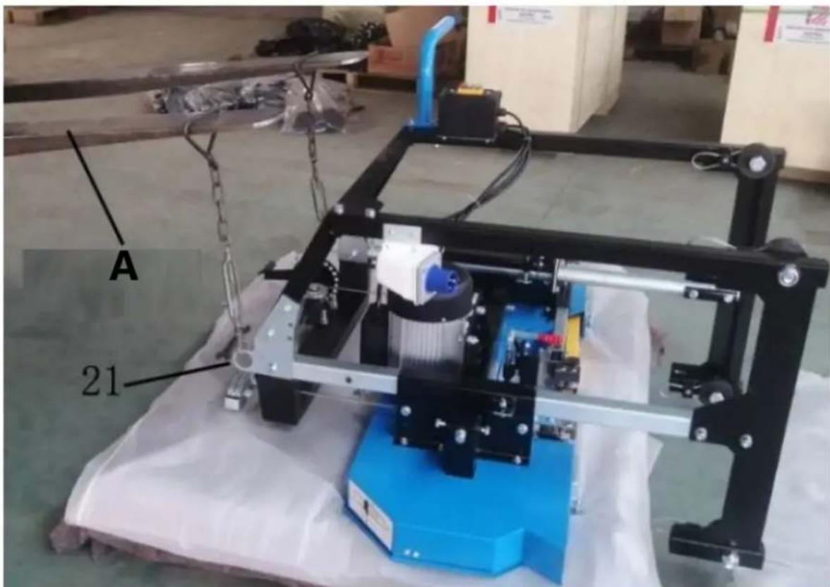
A - Forklift
natural_image
Industrial machine with blue frame and black frame, suspended by chains and weights (no visible text or symbols)Push the machine carriage forward and back the track system to ensure that the width of the track allows for the saw head to move freely. If it binds, the "L" rails will need to be set further or closer together to achieve a consistent width along the entire track system. Once the desired width is achieved, all nuts and bolts can be tightened to the log bunks.
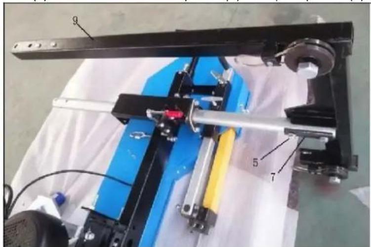
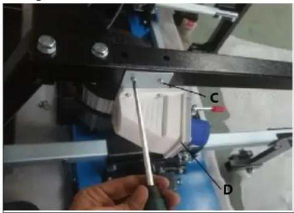
Assemble coolant system at back side of Joint bracket, please note that two bolts fixing Steel rope holder need to be reused, firstly only take off two nuts & washers and mount the Support post for tank and then tighten two nuts, must be careful during the time of assembly. And then put the plastic tank into the Support post, finally connect the water tube from Liquid tank to Spray mounted on the blade guide.
natural_image
Close-up of hands assembling a mechanical bracket with metal fittings and bolts (no visible text or symbols)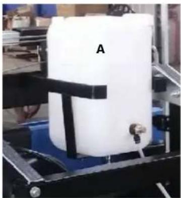
natural_image
White cylindrical container labeled 'A' being handled by a mechanical device (no visible text or symbols on the container itself)
A – Liquid tank
B - Sprayer
Note: We recommend adding some dishwashing liquid to the tank to help lubricate the wood – two to three capfuls.
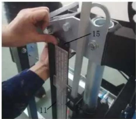
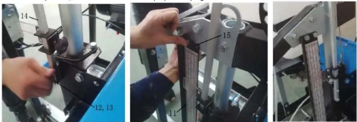
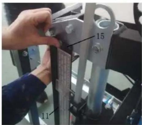
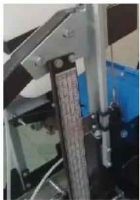
Find the Pointer complete (14) and Scale bracket (11), fix the Pointer complete at the right side of Sliding tube on the Saw head, use these parts supplied (12, 13). And fix the Scale bracket at the right side of Joint plate A, use the bolts and nuts (15). Finally tighten all the bolts.
Using a tape measure, take a measurement at left and right side from the blade to the top of the cross arm. If there is no tape measure in the hand, one steel tube can be put onto the top side of the cross arm to check the distance at both sides. The distance should be equal at both sides. If it isn't equal, the height of left or right side of saw head can be adjusted by adjusting the tension of steel rope, and then turning the lift handle to make saw head lightly go up and down to get the balance at two sides. Finally the good parallel between saw blade and top surface of cross arm should be gotten.
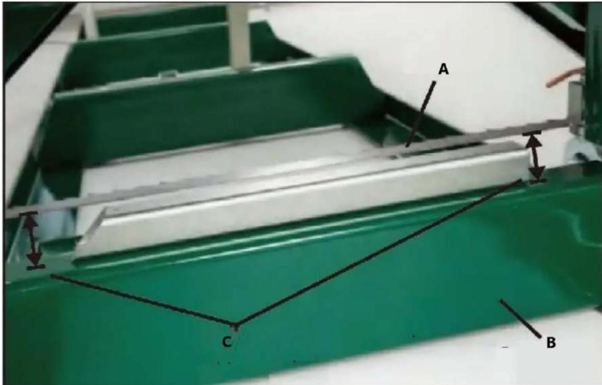
A - Saw blade
B - Cross arm
C - Check distance at two sides
natural_image
Industrial machine with blue frame and labeled components A and B, no visible text or symbols beyond labelsA – Right side of the mill B – Left side of the mill
Notice:
Always cut in the direction shown above. The log clamp should always be at the right side of the log and the log supports should always be at the left. Failure to cut in this direction can cause the log to come lose and possibly even cause damage or injury.
Now that your sawmill is assembled, please run through the "SAWMILL SET-UP PROCEDURES" in the following section. Failure to do so may result in poor sawing performance, damage or injury.
SAWMILL SET-UP PROCEDURES
BELT TENSION
natural_image
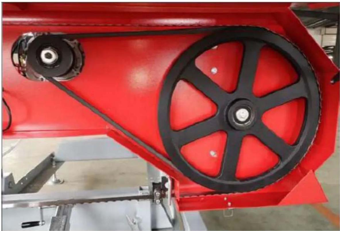
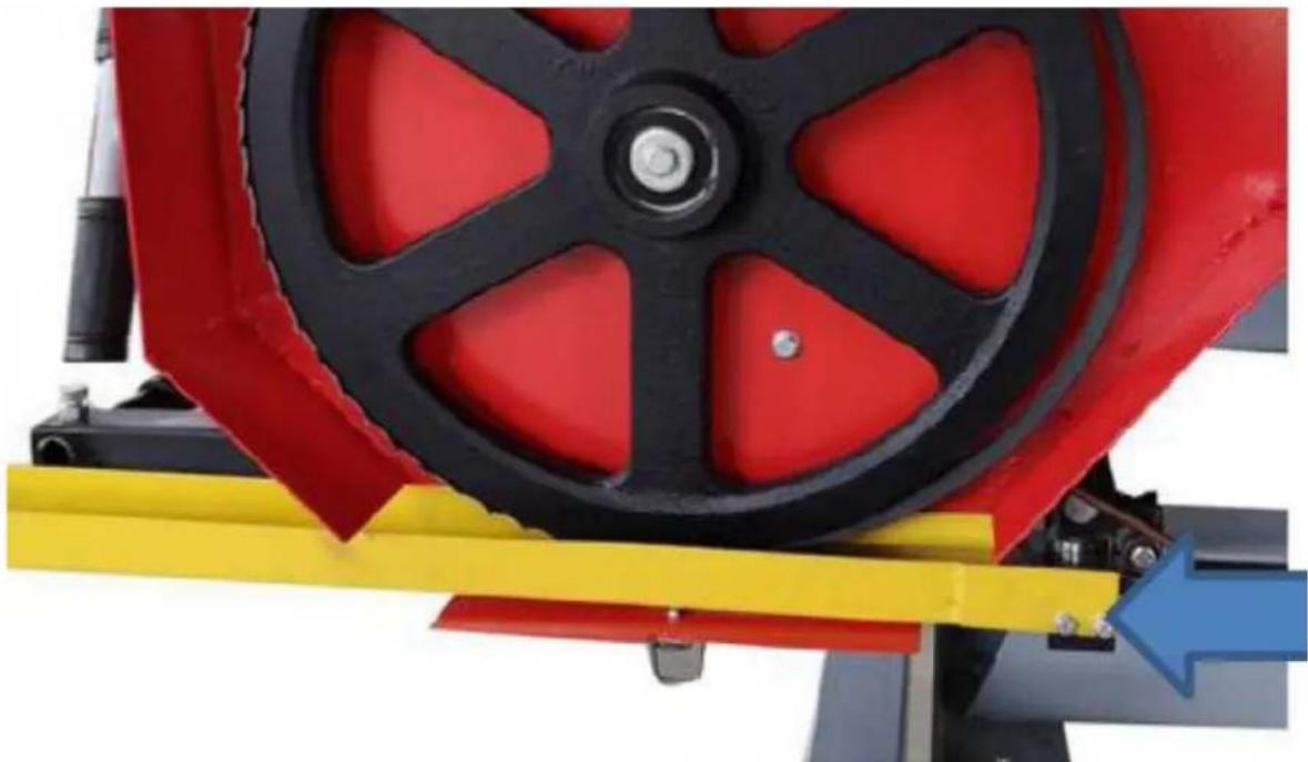
Close-up of a red industrial machine with black pulley and belt drive mechanism (no visible text or symbols)To check the belt tension, with your hand, firmly try to deflect the belt up and down. These should be no more than 1/4" of deflection in both directions (1/2" total). If the belt deflects more than this, it will need to be tightened as described below.
natural_image
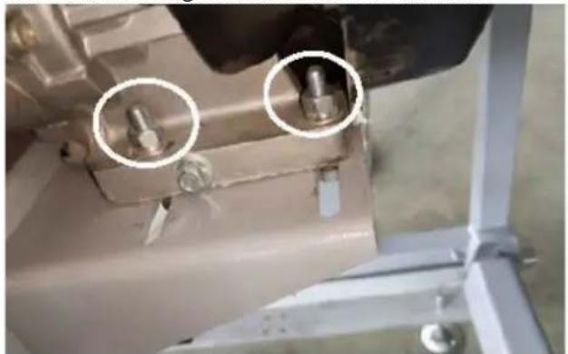
Close-up of a mechanical assembly with two circular annotations highlighting features (no readable text or symbols)
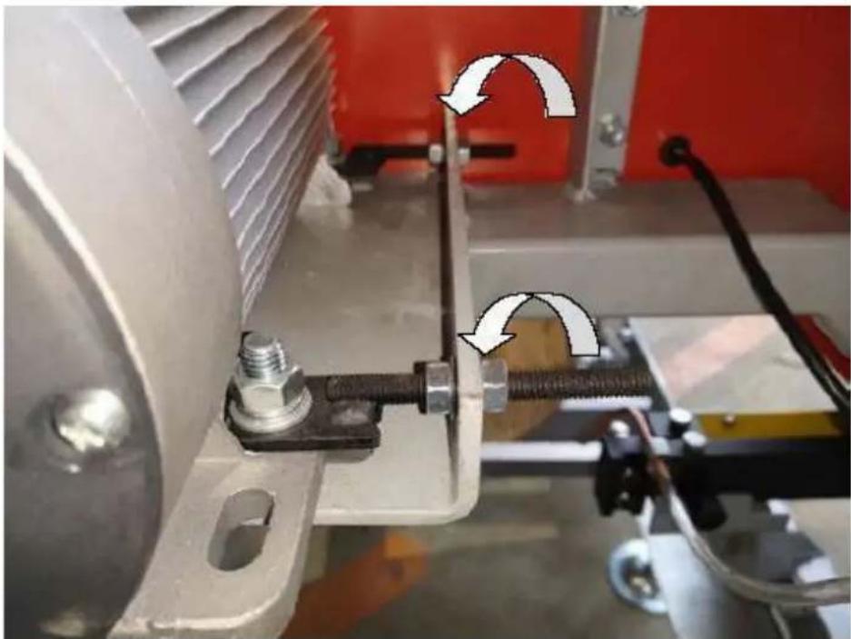
To change the drive side belt, loosen the four bolts that secure the engine to the engine mount using a 16mm wrench.
Now that the motor is free to slide on the motor mounting plate, turn the 13mm nut(A) on the horizontal stud in the anticlockwise direction, push the motor towards the stud and apply more tension on the belt. Do this step incrementally while checking the belt for proper deflection. It is also important to ensure that the motor remains perpendicular to the drive belt. Over tightening can cause the motor to twist on the mounting plate, resulting in belt alignment issues and premature wear. Once the desired belt tension is set, tighten the four engine bolts. Alternatively, if the drive belt is too tight, turn the 13mm nut(B) on the horizontal stud anticlockwise direction, push the motor away from the stud.
BLADE TRACKING
Never attempt the below action when the engine running. As a safety precaution, remove the spark plug cap. It is also advised to wear gloves and safety glasses when working with the blades as it is extremely sharp.

natural_image
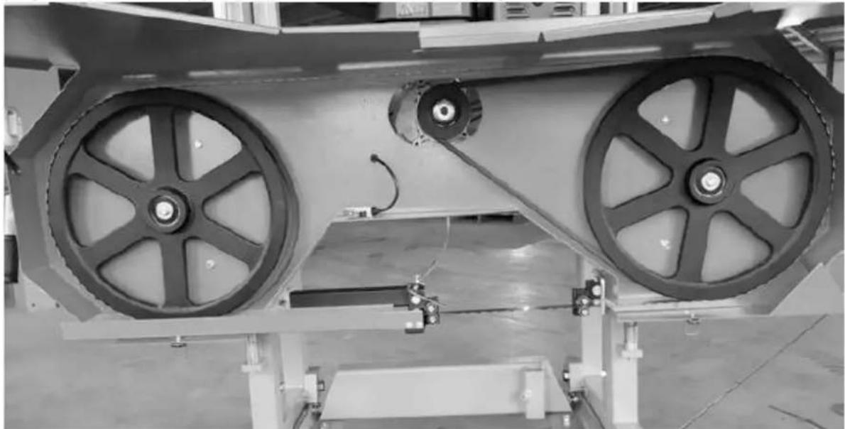
Industrial machinery with two large circular wheels and connecting rods, no visible text or symbols
A – Rearward direction B – Forward direction
The blade should run with the same tooth to band wheel face distance on both sides. Measure the distance from the tip of the blade tooth to the front face of the band wheel on both sides. If an adjustment on either side is required, the below steps will detail this procedure.
natural_image
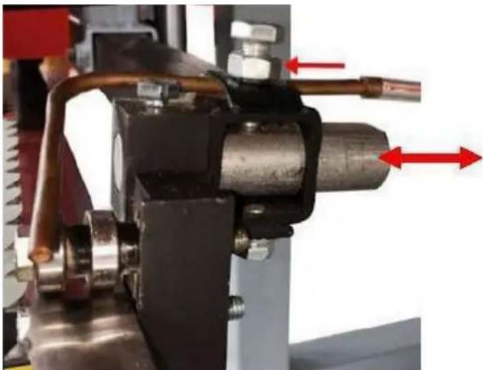
Close-up of a mechanical assembly with red arrows indicating direction of motion or force, no visible text or symbols.Loosen the blade guide assembly bolt with a 13mm socket. The round shaft should now be free to slide rearward and out of the way. Perform this step on both guide assemblies. This will ensure that the guide bearing do not influence tracking of the blade while adjusting.
natural_image
Person using a tool to lift a red industrial fan component, no visible text or symbolsTake some tension off of the blade by turning the "T" handle in the counter-clockwise direction one full turn from full tension position.
Adjusting The Right Hand Side
natural_image
Industrial machine with mechanical components and a red arrow pointing to a pipe connection (no visible text or symbols)Loosen the tracking alignment bolt with an adjustable wrench. The alignment bolt can now be turned to change the angle of the band wheel and track the blade. To move the blade more rearward on the band wheel, this bolt will need to be turned clockwise. Alternatively, turning the bolt in the counterclockwise direction would force the blade to run more forward on the band wheel.
natural_image
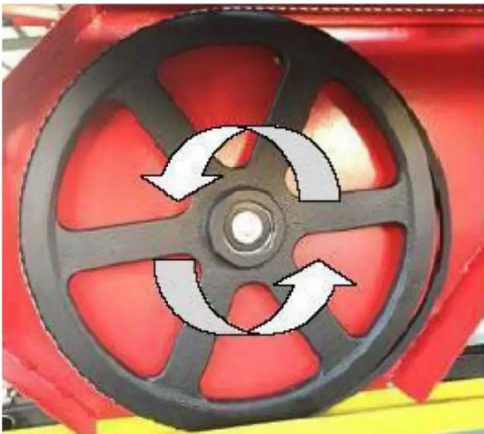
Close-up of a red industrial wheel with three circular arrows indicating rotational flow (no text or symbols)
A – Rearward direction B – Forward direction
Wearing gloves, spin the band wheel with your hand and observe how the blade has changed tracking. Measure the distance again and repeat the above step to further compensate if required.
Adjusting The Left Hand Side
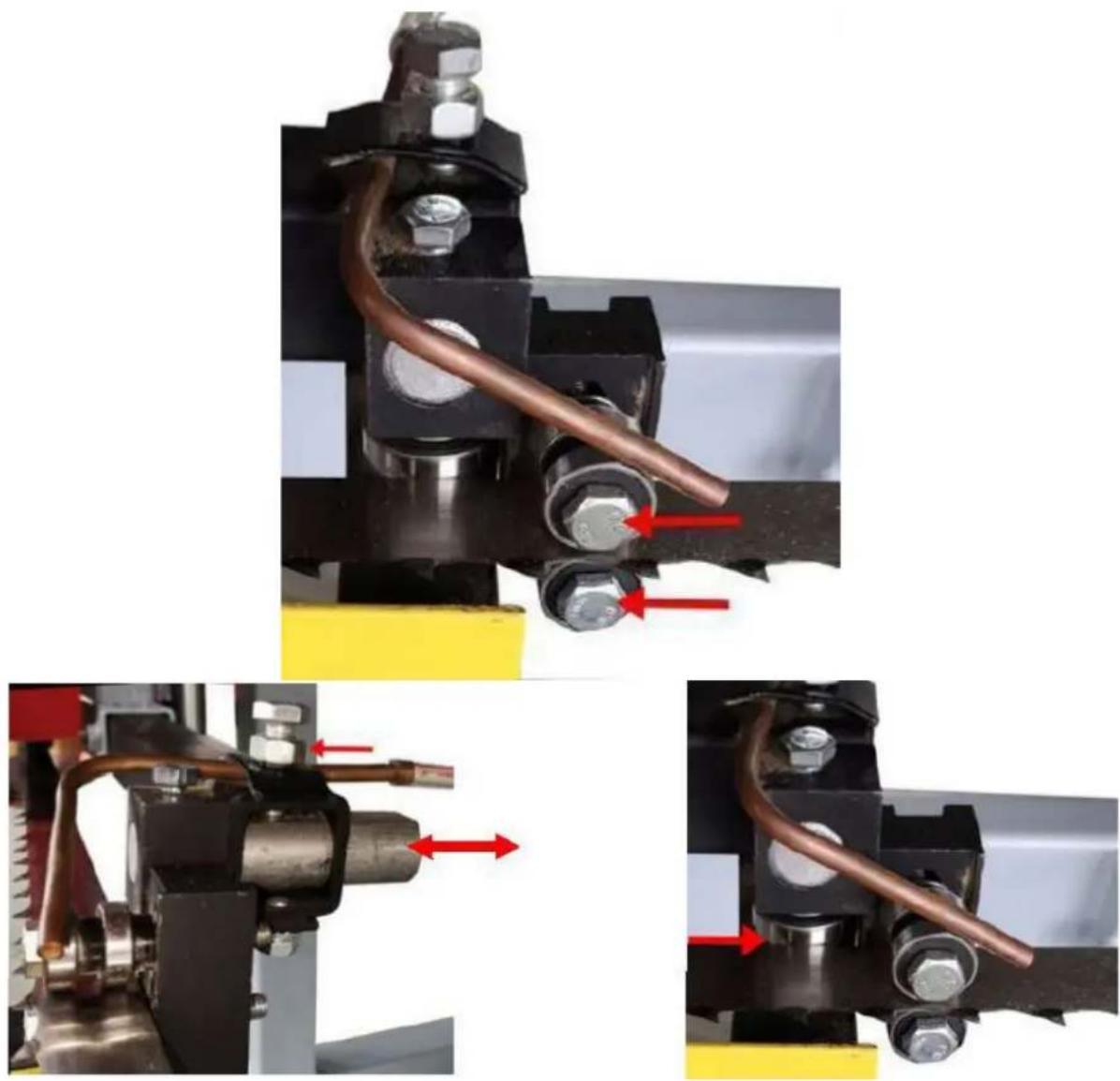
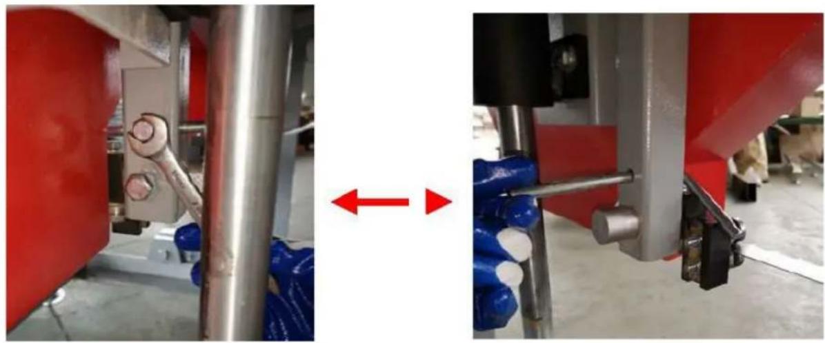
To adjust the left side of the sawmill, again start by taking the tension off of the blade by turning the "T" handle one turn in the counter-clockwise direction. Using a 16m wrench, loosen both "vertical bolts" a 1/2 turn. This will take the clamping force off of the band wheel shaft cause by these two bolts and allow it to move freely in the following steps.

A – Horizontal bolt B – Vertical bolt C – Horizontal inside nut D – Bottom vertical bolt E – Horizontal outside nut
Moving The Blade Forward
Using a 16mm wrench, hold the "horizontal bolt" stationary with a wrench and turn the "horizontal inside nut" counter-clockwise a 1/2 turn. Still holding the "horizontal bolt" stationary, turn the "horizontal outside nut" clockwise a 1/2 turn. This has now shifted the "horizontal bolt" and band wheel shaft, causing the blade to track more forward.
Moving The Blade Rearward
Using a 16mm wrench, hold the “horizontal bolt” stationary with a wrench and turn the “horizontal outside nut” counter-clockwise a 1/2 turn. Still holding the “horizontal bolt” stationary, turn the “horizontal inside nut” clockwise a 1/2 turn. This step has now shifted the “horizontal bolt” and ban wheel shaft, causing the blade to track more forward. Tighten the vertical bolts, then nuts to clamp the band wheel shaft into the vertical position.
natural_image
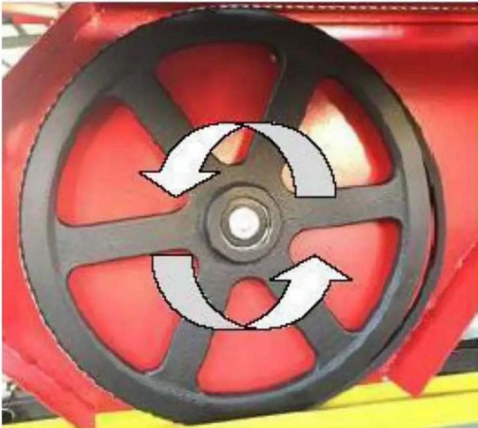
Close-up of a red industrial wheel with three circular arrows indicating rotational cycles (no text or symbols)
A – Rearward direction B – Forward direction
Re-tension the blade by turning the "T" handle a full turn in the clockwise direction. Wearing gloves, spin the ban wheel with your hand and observe how the blade has changed tracking. Measure the distance again and repeat the above step to further compensate if required. Once the blade is tracking true, bring the blade guide assemblies back up to the blade. Keep a paper width distance between the blade guide bearing and the back of the blade. More information on this set up can be found in the next section – "BLADE GUIDE ADJUSTMENT"
BLADE GUIDE ADJUSTMENT
Never attempt the below action when the engine running. As a safety precaution, remove the spark plug cap. It is also advised to confirm that the blade is tracking properly before performing the below. Blade tracking is covered in the previous page. Using a 13mm wrench loosen the blade guide bolt on both the left and right sides. They should be free to slide up and down.
Loosen the blade guide assembly bolt with a 13mm socket. The round shaft should now be free to slide back and forth. Position it so that there is a paper width gap between the bearing and the back of blade. Tighten bolt against the flat on the shaft to secure assembly back in position. Using a piece of paper in between the blade and blade guide blocks, tighten the bearing bolts.
BLADE TENSION

natural_image
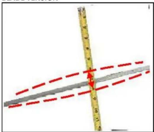
Person cleaning a red industrial component with a tool, no visible text or symbolsProper blade tension is achieved when the blade deflects no more than a total of 1/8" – 1/4" up/down when it is firmly moved by hand at the centre location of the blade guide blocks. Turning the blade tension "T" handle in the clockwise direction will add tension to blade.

natural_image
Industrial machine with white frame and black components, red background (no visible text or symbols)When tensioning the blade, make sure the tracking adjustment bolt sitting behind the "T" handle (pictured) is sitting back in its recess after you have finished and before the mill is run. Failure to do this will result in the blade being thrown and possibly broken.

natural_image
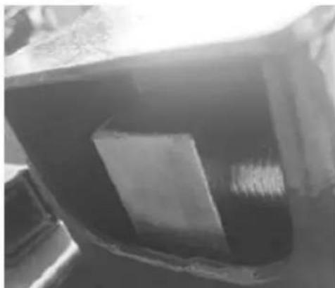
Close-up of a mechanical component with a red circle highlighting a specific area (no visible text or symbols)Tracking adjustment bolt out of recess, of it looks like this DO NOT start the mill until it is resting back in its recess.
natural_image
Close-up of a dark, rectangular object with a white rectangular block inside, possibly a container or container (no visible text or symbols)Tracking adjustment bolt sitting in recess. It should look like this before the mill is started back up.
natural_image
Close-up of a red and black mechanical component with yellow and blue directional arrows indicating movement or force (no text or symbols)Ensure the blade support arm is locked into place after tensioning the blade.
SAWMILL MAINTENANCE
CHANGING THE BLADE
Never attempt the below action when the engine running. As a safety precaution, remove the power plug. Gloves and safety glasses must be worn when changing blade.
natural_image
Industrial machinery with two large circular wheels mounted on a platform, no visible text or symbolsLoosen the screw and pull back the blade limit lever.
natural_image
Two industrial machinery components: a red pipe joint and a blue-capped clamp, both with red arrows indicating bidirectional movement (no text or symbols visible)Loosen the screw and pull out the blade guard cover.
natural_image
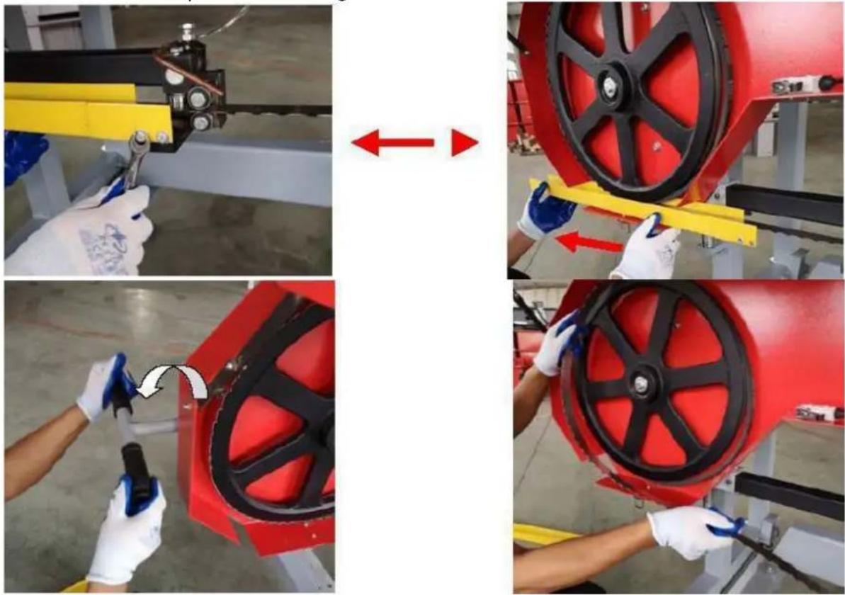
Three-panel image showing a red industrial machine being adjusted, with toolbars and a close-up of the process (no visible text or symbols)Remove the tension in the blade by turning the "T" handle in the counter-clockwise direction. The blade should now be loose and free to pull straight out the front. The new blade can now be installed, guards closed and proper blade tension set.
REPLACING BELTS
Never attempt the below action when the engine running. As a safety precaution, remove the power plug. Gloves and safety glasses must be worn when replacing the belts.
Replacement the belt need to remove the blade firstly, please follow above steps to remove the blade.
There are two rubber "V" belt on the sawmill and they should be replaced as a set. It is not advised to replace individual belts separately. It is recommended to use a BX50 cogged belt for the drive side and a BX41 follow belt.

natural_image
Close-up of a mechanical assembly with two circular annotations highlighting features (no readable text or symbols)
To change the drive side belt, loosen the four bolts that secure the engine to the engine mount using a 16mm wrench.
natural_image
Mechanical assembly with a bolted spring and two curved arrows indicating rotational motion (no text or symbols)Now the motor is free to slide on the mounting plate, turn the 13mm nut on the horizontal stud in the counter-clockwise direction. This will allow the motor to move and will also take the tension off of the belt. The old belt can be removed and the new belt can be installed. Tension the new belt and refer to the BELT TENSION instructions described in the sawmill set up section of the manual. The follower belt can now be changed by simply pulling it off and installing the new one. The blade can now be re-installed, guards closed and proper blade tension set.
Note that blade tracking is likely to change and need adjusting when new belts are installed. Refer to "BLADE TRACKING" for more information.
Note – It is very important to take the tension off of the blade by turning the “T” handle in the counter-clockwise direction when the sawmill is not in use. Failure to do so, will result in flat spots on the rubber belts. These flat spots will cause the mill to vibrate excessively during next use.

natural_image
Metal ladder structure with multiple ladders and mounting feet (no text or symbols visible)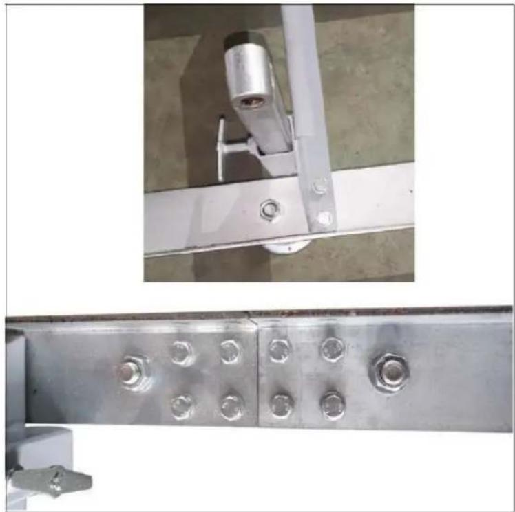
natural_image
Close-up of two metal structural components with bolt holes, shown from different angles (top: white frame; bottom: metallic plate with bolts)natural_image
Close-up of a metallic mechanical assembly with bolts and a circular base (no visible text or symbols)natural_image
Two metallic mechanical tools: a clamping device and a measuring tool, shown from different angles (no text or symbols visible)natural_image
Close-up of a metal ladder structure with attached clips and a horizontal bar, showing red directional arrows (no text or symbols)natural_image
Person using a metal exercise machine with blue gloves and black shoes (no visible text or symbols)natural_image
Close-up of a green and red line drawing on a wooden structure with grassy ground (no text or symbols)
natural_image
Close-up of a green mechanical component being inserted into a wooden surface, with no visible text or symbols.natural_image
Person installing or adjusting a green metal frame structure on a grassy field, with red arrows indicating motion direction (no text or symbols visible)Montaż wózka
natural_image
Mechanical testing setup with black and red components mounted on a blue base, placed on white fabric (no visible text or symbols)A – Napięcie ostrza
natural_image
Industrial machine with blue frame and black frame, suspended by chains and weights (no visible text or symbols)natural_image
Close-up of hands assembling a mechanical bracket with metal parts and bolts (no visible text or symbols)
natural_image
White cylindrical container labeled 'A' being handled by a mechanical device (no visible text or symbols on the container itself)
A – Zbiornik na ciecz
B – Opryskiwacz
natural_image
Industrial machine with blue frame structure and labeled components A and B, no visible text or symbols beyond labelsnatural_image
Close-up of a red industrial machine with black pulley and belt drive mechanism (no visible text or symbols)natural_image
Close-up of a mechanical assembly with two circular annotations highlighting features (no readable text or symbols)
natural_image
Industrial machine with two large wheel wheels and connecting pipes, no visible text or symbols
natural_image
Close-up of a mechanical assembly with red arrows indicating direction or force, no visible text or symbolsnatural_image
Person in gloves and blue gloves handling a red industrial fan component with a white arrow indicating rotation (no text or symbols visible)natural_image
Industrial machine with white frame and black wheels, red background (no visible text or symbols)natural_image
Close-up of a red industrial wheel with three circular arrows indicating rotational flow (no text or symbols)
natural_image
Close-up of a red industrial pulley with three circular arrows indicating rotational flow (no text or symbols)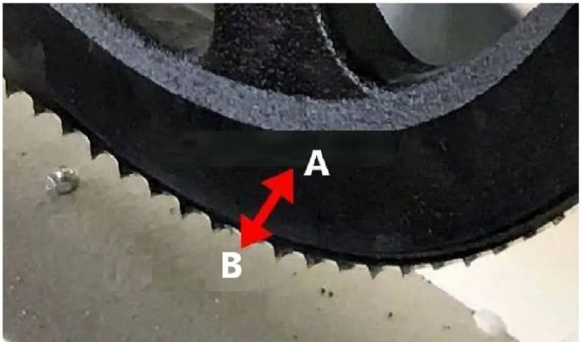
natural_image
Three-panel mechanical assembly diagram showing pipe connection and red directional arrows (no text or symbols)
natural_image
Person cleaning a red industrial component with a tool, no visible text or symbolsnatural_image
Industrial machine with white frame and black components, red background (no visible text or symbols)natural_image
Close-up of a mechanical component with a red circle highlighting a specific area (no visible text or symbols)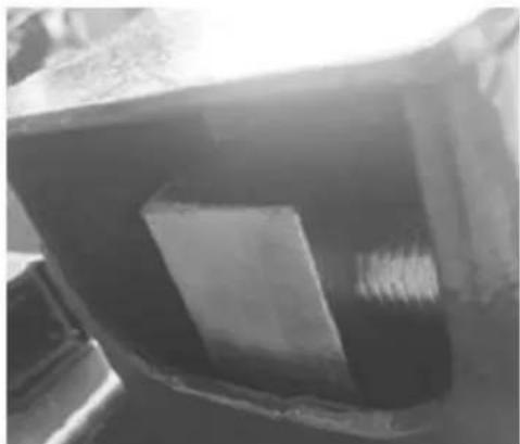
natural_image
Close-up of a dark, rectangular object with a white rectangular block inside, possibly a container or mechanical part (no visible text or symbols)natural_image
Close-up of a red and black wheel with yellow and blue tape, no visible text or symbolsnatural_image
Industrial machinery with two large circular wheels and a connecting rod, mounted on a platform (no visible text or symbols)natural_image
Close-up of a mechanical assembly with two circular annotations highlighting features (no readable text or symbols)
natural_image
Mechanical assembly with a bolted spring and two curved arrows indicating rotational motion (no text or symbols)natural_image
Metal ladder structure with multiple ladders and mounting feet (no text or symbols visible)
natural_image
Close-up of two metallic structural components with bolt holes, mounted on a white metal frame (no text or symbols visible)natural_image
Close-up of a metallic mechanical assembly with bolts and a base mount (no visible text or symbols)natural_image
Two metallic mechanical tools: a clamping device and a long-handled tool, shown from different angles (no text or symbols visible)natural_image
Close-up of a metal ladder with attached clamps and a horizontal bar, showing red directional arrows (no text or symbols)natural_image
Person using a metal exercise machine with blue gloves and black shoes (no visible text or symbols)natural_image
Close-up of a green metal frame with wooden supports and a red line overlay, set on dry grass (no text or symbols visible)
natural_image
Close-up of a green metal tool pressing down on a wooden surface, with grassy background (no text or symbols visible)natural_image
Person installing or adjusting a green metal frame structure outdoors on grass, with red arrows indicating movement direction (no text or symbols visible)Montáž vozíku
natural_image
Mechanical testing setup with black components mounted on a blue base, no visible text or symbolsA – Napnutí čepele
A – Matice řetězu
B – Ocelové lano
C - Ocelové lano
A – Vypínač
B, C – Šroub s válcovou hlavou
D – Zástrčka.
natural_image
Industrial machine with blue frame and black frame, suspended by chains and weights (no visible text or symbols)natural_image
Close-up of hands assembling or adjusting a mechanical bracket with metal fittings and bolts (no visible text or symbols)
natural_image
White cylindrical container labeled 'A' being handled by a mechanical device (no visible text or symbols on the container itself)
natural_image
Industrial machine with blue frame structure and labeled components A and B, no visible text or symbols beyond labelsnatural_image
Close-up of a red industrial machine with black pulleys and mechanical components (no visible text or symbols)natural_image
Close-up of a mechanical assembly with two circular annotations highlighting features (no readable text or symbols)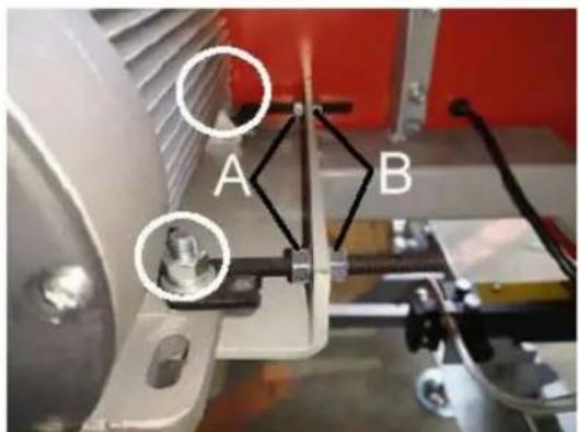
natural_image
Industrial machinery with two large circular wheels and connecting rods, no visible text or symbols
natural_image
Close-up of a mechanical assembly with red arrows indicating direction of motion or force, no visible text or symbols.natural_image
Industrial machine with mechanical components and a red arrow pointing to a pipe connection (no visible text or symbols)natural_image
Close-up of a red industrial wheel with three circular arrows indicating rotational cycles (no text or symbols)
natural_image
Close-up of a red industrial pulley with three circular arrows indicating rotational flow (no text or symbols)

natural_image
Person cleaning a red industrial component with a tool, no visible text or symbolsnatural_image
Industrial machine with white frame and black components, red background (no visible text or symbols)natural_image
Close-up of a mechanical component with a red circle highlighting a specific area (no visible text or symbols)natural_image
Close-up of a dark, rectangular object with a visible internal structure and textured surface (no text or symbols)natural_image
Close-up of a red and black mechanical component with yellow and blue horizontal bars, no visible text or symbols.natural_image
Industrial machinery with two large circular wheels and connecting rods, no visible text or symbolsnatural_image
Two industrial machinery components: a red pipe joint and a blue-capped clamp, both with red arrows indicating bidirectional movement (no text or symbols visible)natural_image
Three-panel image showing a red industrial machine being adjusted, with toolbars and a close-up of the process (no visible text or symbols)natural_image
Close-up of a mechanical assembly with two circular annotations highlighting features (no readable text or symbols)
natural_image
Close-up of a mechanical assembly with a bolted spring and two curved arrows indicating rotational motion (no text or symbols present)natural_image
Metal ladder structure with multiple ladders and mounting feet (no text or symbols visible)
natural_image
Close-up of metallic structural components with bolt holes and mounting brackets (no text or symbols visible)natural_image
Close-up of a metallic mechanical assembly with bolts and a base, mounted on a stand (no visible text or symbols)natural_image
Two metallic mechanical tools: a clamping device and a long-handled tool, shown from different angles (no text or symbols visible)natural_image
Mechanical assembly with metal frame and adjustment lever, no visible text or symbolsnatural_image
Person wearing gloves and blue gloves operating a metal rail bridge with two wheels (no text or symbols visible)natural_image
Close-up of a green and red line drawing on a wooden structure with grassy ground (no text or symbols)
natural_image
Close-up of a green mechanical component being held by a hand, with no visible text or symbols.natural_image
Person assembling a green metal frame structure outdoors on grass, with red arrows indicating motion direction (no text or symbols)Ensemble de chariot
natural_image
Mechanical testing setup with black and red components mounted on a blue base, placed on white fabric (no visible text or symbols)A – Tension de la lame

A – Écrou de chaîne
B – Câble en acier
C – Câble en acier
natural_image
Industrial robotic device with blue frame and black frame, suspended by chains and weights (no visible text or symbols)natural_image
Close-up of hands operating a metal mechanical fixture with bolts and a tool (no visible text or symbols)
natural_image
White cylindrical container labeled 'A' being handled by a black-and-white mechanical device (no visible text or symbols on the container itself)

natural_image
Close-up of a mechanical device with a ruler and clamped components (no visible text or symbols)natural_image
Industrial machine with blue frame structure and labeled components A and B, no readable text or symbols beyond labelsnatural_image
Close-up of a red industrial machine with black pulley and belt drive mechanism (no visible text or symbols)natural_image
Close-up of mechanical components with two circular annotations highlighting features (no readable text or symbols)
natural_image
Industrial machinery with two large wheels and connecting rods, no visible text or symbols
natural_image
Close-up of a mechanical assembly with red arrows indicating direction or force, no visible text or symbolsnatural_image
Person cleaning a red industrial fan with a tool, showing the blade being cut (no text or symbols visible)natural_image
Industrial machine with white frame and black components, red background (no visible text or symbols)natural_image
Close-up of a red industrial wheel with three circular arrows indicating rotational flow (no text or symbols)
natural_image
Close-up of a red industrial wheel with three circular arrows indicating rotational cycles (no text or symbols)
natural_image
Three-panel mechanical assembly diagram showing pipe connection and red directional arrows (no text or symbols)
natural_image
Person cleaning a red industrial component with a tool, no visible text or symbolsnatural_image
Industrial machine with white frame and black components, red background (no visible text or symbols)natural_image
Close-up of a mechanical component with a red circle highlighting a specific area (no visible text or symbols)
natural_image
Close-up of a dark, rectangular object with a white rectangular block inside, possibly a container or mold (no visible text or symbols)natural_image
Close-up of a red and black mechanical component with yellow and blue directional arrows indicating movement or force (no text or symbols)natural_image
Industrial machine with two large pulleys and connecting rods, no visible text or symbolsnatural_image
Two industrial machinery components: a red pipe joint and a blue-capped clamp, both with red arrows indicating bidirectional movement (no text or symbols visible)natural_image
Three-panel sequence showing hands operating a red industrial machine with a tool, demonstrating mechanical assembly and tool path (no text or symbols visible)natural_image
Close-up of a mechanical assembly with two circular annotations highlighting features (no readable text or symbols)
natural_image
Close-up of a mechanical assembly with a bolted spring and two curved arrows indicating rotational motion (no text or symbols present)natural_image
Metal ladder structure with multiple parallel supports and mounting feet (no text or symbols visible)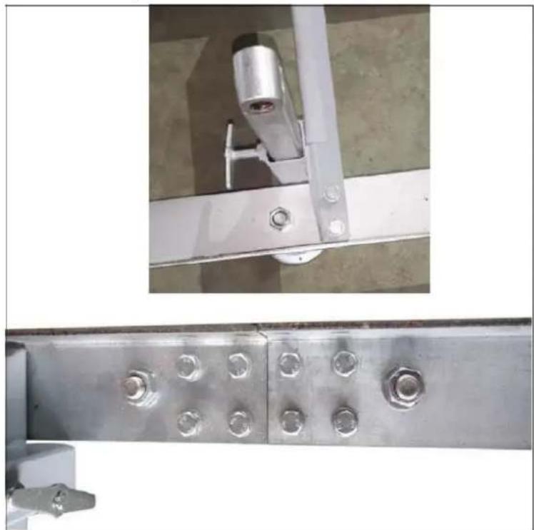
natural_image
Close-up of two metallic structural components with bolt holes and mounting brackets (no text or symbols visible)natural_image
Close-up of a metallic mechanical assembly with bolts and a circular base (no visible text or symbols)natural_image
Two metallic mechanical tools: a clamping device and a long-handled tool, shown from different angles (no text or symbols visible)natural_image
Close-up of a metal frame structure with mounting brackets and a central rod, showing red directional arrows (no text or symbols)natural_image
Person wearing gloves and blue gloves operating a metal frame with two wheels (no text or symbols visible)natural_image
Close-up of a green and red line drawing on a wooden structure with grassy ground (no text or symbols)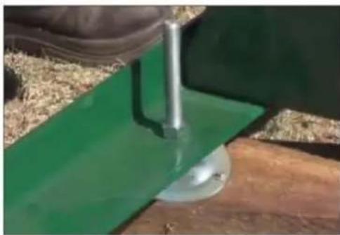
natural_image
Close-up of a green mechanical component being held by a hand, with no visible text or symbols.natural_image
Person assembling a green metal frame structure outdoors on grass, with red arrows indicating motion direction (no text or symbols)natural_image
Mechanical testing setup with black components mounted on a blue base, no visible text or symbolsnatural_image
Industrial robotic device with blue frame and black frame, suspended by chains and weights (no visible text or symbols)natural_image
Close-up of hands operating a metal mechanical fixture with bolts and a tool (no visible text or symbols)
natural_image
White cylindrical container labeled 'A' being processed by a black-and-white robotic arm (no visible text or symbols on the container itself)


natural_image
Close-up of a mechanical device with a ruler and metal frame (no visible text or symbols)natural_image
Industrial machine with blue frame structure and labeled components A and B, no readable text or symbols beyond labelsnatural_image
Close-up of a red industrial machine with black pulley and belt (no visible text or symbols)natural_image
Close-up of a mechanical assembly with two circular annotations highlighting features (no visible text or symbols)
natural_image
Industrial machinery with two large wheels and connecting rods, no visible text or symbols
natural_image
Close-up of a mechanical assembly with red arrows indicating direction or force, no visible text or symbolsnatural_image
Person in gloves and blue gloves handling a red industrial fan component with a white arrow indicating rotation (no text or symbols visible)natural_image
Industrial machine with white frame and black wheels, red background (no visible text or symbols)natural_image
Close-up of a red industrial wheel with three circular arrows indicating rotational flow (no text or symbols)
natural_image
Close-up of a red industrial fan or impeller with three circular arrows indicating rotational flow (no text or symbols)
natural_image
Three-panel mechanical assembly diagram showing pipe connection and red directional arrows (no text or symbols)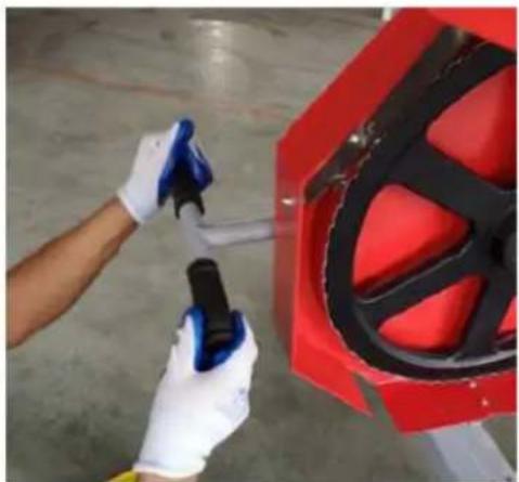
natural_image
Person cleaning a red industrial component with a tool, no visible text or symbolsnatural_image
Industrial machine with mechanical components and red safety panel (no visible text or symbols)natural_image
Close-up of a mechanical component with a red circle highlighting a specific area (no visible text or symbols)natural_image
Close-up of a dark, rectangular object with a glossy surface and a small rectangular block inside (no visible text or symbols)natural_image
Close-up of a red and black mechanical device with a yellow and blue directional arrow indicating movement or force (no text or symbols visible)natural_image
Industrial machinery with two large circular wheels and connecting rods, no visible text or symbolsnatural_image
Two industrial machinery components: a red pipe joint and a blue-capped clamp, both with red arrows indicating bidirectional movement (no text or symbols visible)natural_image
Three-panel image showing a red industrial machine being adjusted, with toolbars and a close-up of the process (no visible text or symbols)natural_image
Close-up of a mechanical assembly with two circular annotations highlighting features (no readable text or symbols)
natural_image
Mechanical assembly with a bolted spring and two curved arrows indicating rotational motion (no text or symbols)natural_image
Metal ladder structure with multiple horizontal ladders and mounting feet (no text or symbols visible)
natural_image
Close-up of two metallic structural components with bolt holes and mounting brackets (no text or symbols visible)natural_image
Close-up of a metallic mechanical assembly with bolts and a circular base (no visible text or symbols)natural_image
Two metallic mechanical tools: a clamping device and a long-handled tool, shown from different angles (no text or symbols visible)natural_image
Mechanical assembly with metal frame and adjustment lever, no visible text or symbolsnatural_image
Person wearing gloves and blue gloves operating a metal rail bridge with two wheels (no text or symbols visible)natural_image
Close-up of a green metal frame with wooden supports and a red diagonal line, set on dry grass (no text or symbols visible)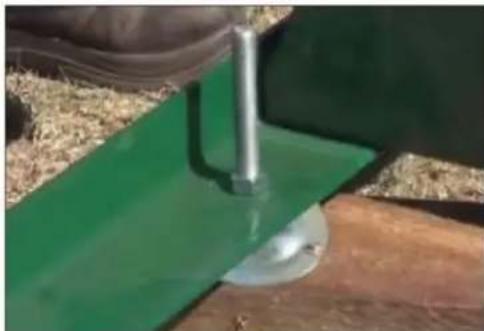
natural_image
Close-up of a green agricultural field with a metal anchor and a circular crop, no visible text or symbolsnatural_image
Person assembling a green metal frame structure outdoors, with red arrows indicating movement or force directions (no text or symbols visible)Conjunto de carro
natural_image
Mechanical testing setup with black components mounted on a blue base, no visible text or symbolsnatural_image
Industrial robotic device with blue frame and black frame, suspended by chains and weights (no visible text or symbols)natural_image
Close-up of hands operating a metal mechanical fixture with bolts and a tool (no visible text or symbols)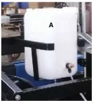
natural_image
White cylindrical container labeled 'A' being processed by a black mechanical device (no visible text or symbols on the container itself)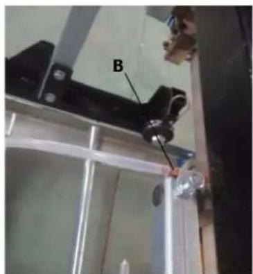


natural_image
Close-up of a mechanical device with a ruler and clamped components (no visible text or symbols)natural_image
Industrial machine with blue frame structure and labeled components A and B, no readable text or symbols beyond labelsnatural_image
Close-up of a red industrial machine with black pulley and belt drive mechanism (no visible text or symbols)natural_image
Close-up of mechanical components with two circular annotations highlighting features (no readable text or symbols)
natural_image
Industrial machinery with two large circular wheels and connecting rods, no visible text or symbols
natural_image
Close-up of a mechanical assembly with red arrows indicating direction or force, no visible text or symbolsnatural_image
Person in gloves and blue gloves handling a red industrial fan component with a white arrow indicating rotation (no text or symbols visible)natural_image
Industrial machine with white frame and black components, red background (no visible text or symbols)natural_image
Close-up of a red industrial wheel with three circular arrows indicating rotational flow (no text or symbols)
natural_image
Close-up of a red industrial wheel with three circular arrows indicating rotational flow (no text or symbols)
natural_image
Three-panel mechanical assembly diagram showing pipe connection and red directional arrows (no text or symbols)
natural_image
Person cleaning a red industrial component with a tool, no visible text or symbolsnatural_image
Industrial machine with white frame and black components, red background (no visible text or symbols)natural_image
Close-up of a mechanical component with a red circle highlighting a specific area (no visible text or symbols)
natural_image
Close-up of a dark, rectangular object with a white rectangular block inside, possibly a container or mechanical part (no visible text or symbols)natural_image
Close-up of a red and black mechanical component with yellow and blue directional arrows indicating movement or force (no text or symbols)natural_image
Industrial machinery with two large circular wheels and connecting rods, no visible text or symbolsnatural_image
Two industrial machinery components: a red pipe with metal fittings and a blue plastic bag, connected by a red double-headed arrow (no visible text or symbols)natural_image
Three-panel image showing a red industrial machine being adjusted, with toolbars and a close-up of the process (no visible text or symbols)natural_image
Close-up of a mechanical assembly with two circular annotations highlighting features (no readable text or symbols)
natural_image
Close-up of a mechanical assembly with a bolted spring and two curved arrows indicating rotational motion (no text or symbols present)natural_image
Metal ladder structure with multiple horizontal ladders and mounting feet (no text or symbols visible)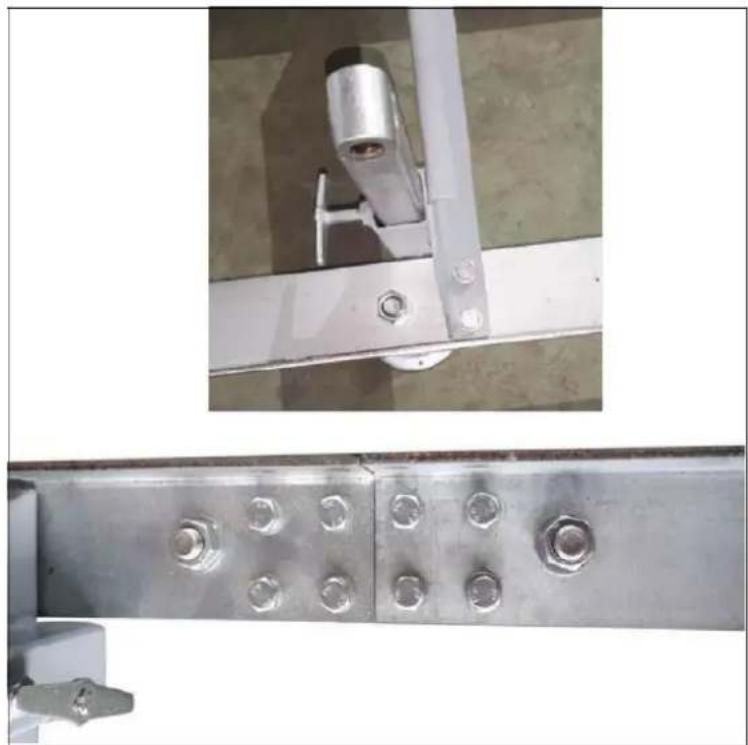
natural_image
Close-up of two metal structural components with bolts and a metallic bracket (no text or symbols visible)natural_image
Close-up of a metallic mechanical assembly with bolts and a base mount (no visible text or symbols)natural_image
Two metallic mechanical tools: a clamping device and a long-handled tool, shown from different angles (no text or symbols visible)natural_image
Close-up of a metal ladder with attached clamps and a horizontal bar, showing red directional arrows (no text or symbols)natural_image
Person using a metal exercise machine with blue gloves and black shoes (no visible text or symbols)natural_image
Close-up of a green and red line drawing on a wooden structure with grassy ground (no text or symbols)
natural_image
Close-up of a green mechanical component being inserted into a wooden surface, with no visible text or symbols.natural_image
Person assembling a green metal frame structure outdoors on grass, with red arrows indicating motion direction (no text or symbols visible)Kocsiszerelvény
natural_image
Mechanical testing setup with black components mounted on a blue base, no visible text or symbolsA - Pengefeszítés

A - Láncanya
B - Acélkötél
C - Acélkötél
D - Emelőfogantyú
natural_image
Industrial machine with blue frame and black frame, suspended by chains and weights (no visible text or symbols)natural_image
Close-up of hands assembling a mechanical bracket with metal parts and bolts (no visible text or symbols)
natural_image
White cylindrical container labeled 'A' being handled by a mechanical device (no visible text or symbols on the container itself)
A - Folyadéktartály
B - permetezőgép
natural_image
Mechanical assembly diagram showing a blue conveyor system with labeled components A and B, no readable text or symbols beyond labels.natural_image
Close-up of a red industrial machine with black pulley and belt (no visible text or symbols)natural_image
Close-up of mechanical components with two circular annotations highlighting features (no readable text or symbols)
natural_image
Industrial machinery with two large circular wheels and connecting rods, no visible text or symbols
natural_image
Close-up of a mechanical assembly with red arrows indicating direction or force, no visible text or symbolsnatural_image
Person in gloves and blue gloves handling a red industrial fan component with a white arrow indicating rotation (no text or symbols visible)natural_image
Industrial machine with white frame and black components, red background (no visible text or symbols)natural_image
Close-up of a red industrial wheel with three circular arrows indicating rotational flow (no text or symbols)
natural_image
Close-up of a red industrial wheel with three circular arrows indicating cycle (no text or symbols)
natural_image
Three-panel mechanical assembly diagram showing pipe connection and red directional arrows (no text or symbols)
natural_image
Person cleaning a red car wheel rim with a tool, no visible text or symbolsnatural_image
Industrial machine with mechanical components and red safety panel (no visible text or symbols)natural_image
Close-up of a mechanical component with a red circle highlighting a specific area (no visible text or symbols)natural_image
Close-up of a dark, rectangular object with a small square cutout and textured surface (no visible text or symbols)natural_image
Close-up of a red and black mechanical component with yellow and blue directional arrows indicating movement or force (no text or symbols)natural_image
Industrial machinery with two large circular wheels and connecting rods, no visible text or symbolsnatural_image
Two industrial machinery components: a red pipe joint and a blue-capped clamp, both with red arrows indicating bidirectional movement (no text or symbols visible)natural_image
Three-panel sequence showing hands operating a red industrial machine with blue gloves, demonstrating mechanical assembly and tooling (no text or symbols visible)natural_image
Close-up of a mechanical assembly with two circular annotations highlighting features (no readable text or symbols)
natural_image
Close-up of a mechanical assembly with a bolted spring and two curved arrows indicating rotational motion (no text or symbols present)natural_image
Metal ladder structure with multiple ladders and wheels, no visible text or symbols
natural_image
Close-up of two metallic structural components with bolt holes, shown from different angles (top: metal frame, bottom: steel plate with bolts)natural_image
Close-up of a metallic mechanical assembly with bolts and a base mount (no visible text or symbols)natural_image
Two metallic mechanical tools or clamps shown from different angles (top: bracket, bottom: rod), no visible text or symbols.natural_image
Close-up of a metal ladder with attached clamps and a horizontal bar, showing red directional arrows (no text or symbols)natural_image
Person using a metal exercise machine with blue gloves and black shoes (no visible text or symbols)natural_image
Close-up of a green metal frame with a red line and green arrow pointing to a wooden post (no text or symbols visible)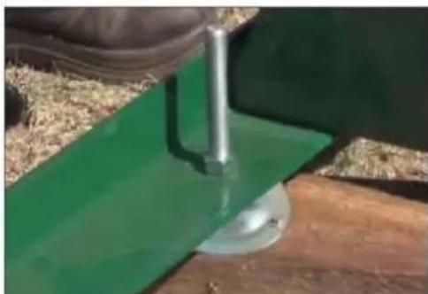
natural_image
Close-up of a hand using a metal tool to lift a green wet concrete block on wooden ground (no text or symbols visible)natural_image
Person assembling a green metal frame structure outdoors on grass, with red arrows indicating motion direction (no text or symbols visible)Montering af vogn
natural_image
Mechanical testing setup with black components mounted on a blue base, no visible text or symbolsA - Knivspænding
A - Strømafbryder B, C - Panhovedskrue D - Stik.
natural_image
Industrial machine with blue frame and black frame, suspended by chains and weights (no visible text or symbols)natural_image
Close-up of hands assembling a mechanical bracket with metal fittings and bolts (no visible text or symbols)
natural_image
White cylindrical container labeled 'A' being handled by a mechanical device (no visible text or symbols on the container itself)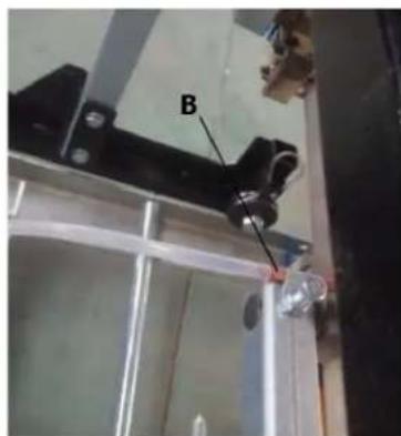
A - Væsketank
B - Sprøjte
natural_image
Industrial machine with blue frame and labeled components A and B, no visible text or symbols beyond labelsnatural_image
Close-up of a red industrial machine with black pulley and belt (no visible text or symbols)natural_image
Close-up of mechanical components with two circular annotations highlighting features (no readable text or symbols)
natural_image
Industrial machinery with two large circular wheels and connecting rods, no visible text or symbols
natural_image
Close-up of a mechanical assembly with red arrows indicating direction of motion or force, no visible text or symbols.natural_image
Person cleaning a red car interior with a tool, showing a curved arrow indicating rotation (no text or symbols visible)natural_image
Industrial machine with white frame and black wheels, red background (no visible text or symbols)natural_image
Close-up of a red industrial wheel with three circular arrows indicating cycle (no text or symbols)
natural_image
Close-up of a red industrial pulley with three circular arrows indicating rotational flow (no text or symbols)

natural_image
Person cleaning a red industrial component with a tool, no visible text or symbolsnatural_image
Industrial machine with white frame and black components, red background (no visible text or symbols)natural_image
Close-up of a mechanical component with a red circle highlighting a specific area (no visible text or symbols)natural_image
Close-up of a dark, rectangular object with a visible internal structure and textured surface (no text or symbols)natural_image
Close-up of a red and black mechanical component with yellow and blue directional arrows indicating movement or force (no text or symbols)natural_image
Industrial machine with two large circular wheels mounted on a platform, no visible text or symbolsnatural_image
Two industrial machinery components: a red pipe joint and a blue-capped clamp, both with red arrows indicating bidirectional movement (no text or symbols visible)natural_image
Three-panel image showing a red industrial machine being adjusted, with toolbars and a close-up of the process (no visible text or symbols)natural_image
Close-up of a mechanical assembly with two metallic components and a circular annotation (no visible text or symbols)
natural_image
Close-up of a mechanical assembly with a bolted spring and red panel, showing motion arrows (no text or symbols)natural_image
Metal ladder structure with multiple horizontal supports and wheels, no visible text or symbols
natural_image
Close-up of two metallic structural components with bolt holes, shown from different angles (top: metal frame, bottom: steel plate with bolts)natural_image
Close-up of a metallic mechanical assembly with bolts and a base mount (no visible text or symbols)natural_image
Two metallic mechanical tools or fixtures, one with a handle and metal bracket, the other with a long rod (no visible text or symbols)natural_image
Close-up of a metal frame structure with mounting brackets and a central rod, showing red directional arrows (no text or symbols)natural_image
Person wearing gloves and blue gloves operating a metal frame with two wheels (no text or symbols visible)natural_image
Close-up of a green and red line drawing on a wooden structure with grassy ground (no text or symbols)
natural_image
Close-up of a green mechanical component being inserted into a wooden surface, with no visible text or symbols.natural_image
Person installing or maintaining a green metal frame structure outdoors on grass, with red arrows indicating movement direction (no text or symbols visible)Vaunun kokoonpano
natural_image
Mechanical device with black components mounted on a blue base, placed on white fabric (no visible text or symbols)A – Terän kireys
natural_image
Industrial machine setup with labeled components (C, D, E) and wiring, no readable text or symbols beyond labelsnatural_image
Industrial machine with blue frame and black frame, suspended by chains and weights (no visible text or symbols)natural_image
Close-up of hands operating a metal mechanical assembly with bolts and a blue component (no visible text or symbols)
natural_image
White cylindrical container labeled 'A' being handled by a mechanical device (no visible text or symbols on the container itself)
A – Nestesäiliö
B - Ruisku
natural_image
Industrial machine with blue frame structure and labeled components A and B, no visible text or symbols beyond labelsnatural_image
Close-up of a red industrial machine with black pulley and belt drive mechanism (no visible text or symbols)natural_image
Close-up of a mechanical assembly with two circular annotations highlighting features (no readable text or symbols)
natural_image
Industrial machine with two large wheel wheels and connecting pipes, no visible text or symbols
natural_image
Close-up of a mechanical assembly with red arrows indicating direction of motion or force, no visible text or symbols.natural_image
Person cleaning a red car interior with a tool, showing a curved arrow indicating rotation (no text or symbols visible)natural_image
Industrial machine with white frame and black wheels, red background (no visible text or symbols)natural_image
Close-up of a red industrial wheel with three circular arrows indicating cycle (no text or symbols)
natural_image
Close-up of a red industrial pulley with three circular arrows indicating rotational flow (no text or symbols)

natural_image
Person cleaning a red industrial component with a tool, no visible text or symbolsnatural_image
Industrial machine with white frame and black components, red background (no visible text or symbols)natural_image
Close-up of a mechanical component with a red circle highlighting a specific area (no visible text or symbols)natural_image
Close-up of a dark, rectangular object with a visible internal structure and textured surface (no text or symbols)natural_image
Close-up of a red and black tire roller being adjusted with yellow and blue guide rails (no text or symbols visible)natural_image
Industrial machinery with two large circular wheels and connecting rods, no visible text or symbolsnatural_image
Two industrial machinery components: a red pipe joint and a blue-capped clamp, both with red arrows indicating bidirectional movement (no text or symbols visible)natural_image
Three-panel image showing a red industrial machine being adjusted, with toolbars and a close-up of the process (no visible text or symbols)natural_image
Close-up of a mechanical assembly with two circular annotations highlighting features (no visible text or symbols)
natural_image
Close-up of a mechanical assembly with a bolted spring and red panel, showing motion arrows (no text or symbols)natural_image
Metal ladder structure with multiple horizontal ladders and mounting feet (no text or symbols visible)
natural_image
Close-up of two metal structural components with bolts and a metallic bracket (no text or symbols visible)natural_image
Close-up of a metallic mechanical assembly with bolts and a base, no visible text or symbolsnatural_image
Two metallic mechanical tools: a clamping device and a measuring tool, shown from different angles (no text or symbols visible)natural_image
Close-up of a metal frame structure with mounting brackets and a central rod, showing red directional arrows (no text or symbols)natural_image
Person wearing gloves and blue gloves operating a metal frame with two wheels (no text or symbols visible)natural_image
Close-up of a green and red line drawing on a wooden structure with grassy ground (no text or symbols)
natural_image
Close-up of a green mechanical component being inserted into a wooden surface, with no visible text or symbols.natural_image
Person assembling a green metal frame structure outdoors on grass, with red arrows indicating motion direction (no text or symbols visible)Wagenmontage
natural_image
Mechanical device with black components mounted on a blue base, placed on white fabric (no visible text or symbols)A - Bladspanning
A - Kettingmoer
B – Stalen kabel
C – Stalen kabel
D – Hendel optillen
E - Vergrendelingshendel
natural_image
Industrial robotic device with blue frame and black frame, suspended by chains and weights (no visible text or symbols)natural_image
Close-up of hands installing or adjusting a mechanical component with metal brackets and bolts (no visible text or symbols)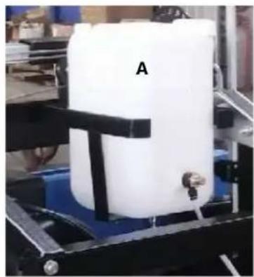
natural_image
White cylindrical container labeled 'A' being processed by a black-and-white robotic arm (no visible text or symbols on the container itself)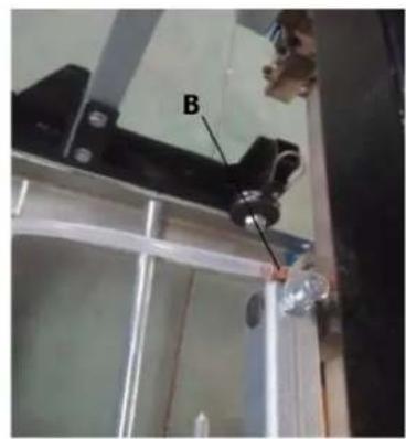

natural_image
Close-up of a mechanical device with a ruler and clamped components (no visible text or symbols)natural_image
Industrial machine with blue frame and labeled components A and B, no visible text or symbols beyond labelsnatural_image
Close-up of a red industrial machine with black pulley and belt drive mechanism (no visible text or symbols)natural_image
Close-up of mechanical components with two circular annotations highlighting features (no readable text or symbols)
natural_image
Industrial machinery with two large circular wheels and connecting rods, no visible text or symbols
natural_image
Close-up of a mechanical assembly with red arrows indicating direction or force, no visible text or symbolsnatural_image
Person cleaning a red industrial fan with a tool, showing the blade being cut (no text or symbols visible)natural_image
Industrial machine with white frame and black wheels, red background (no visible text or symbols)natural_image
Close-up of a red industrial wheel with three circular arrows indicating rotational flow (no text or symbols)
natural_image
Close-up of a red industrial fan or impeller with three circular arrows indicating rotational flow (no text or symbols)
natural_image
Three-panel mechanical assembly diagram showing pipe connection and red directional arrows (no text or symbols)
natural_image
Person cleaning a red industrial component with a tool, no visible text or symbolsnatural_image
Industrial machine with metal frame and pipe assembly, red background (no visible text or symbols)natural_image
Close-up of a mechanical component with a red circle highlighting a specific area (no visible text or symbols)natural_image
Close-up of a dark, rectangular object with a glossy surface and a small rectangular block inside (no visible text or symbols)natural_image
Close-up of a red and black mechanical device with yellow and blue directional arrows indicating movement or force (no text or symbols)natural_image
Industrial machinery with two large circular wheels and connecting rods, no visible text or symbolsnatural_image
Two industrial machinery components: a red pipe joint and a blue-capped clamp, both with red arrows indicating bidirectional movement (no text or symbols visible)natural_image
Three-panel image showing a red industrial machine being adjusted, with toolbars and a close-up of the process (no visible text or symbols)natural_image
Close-up of a mechanical assembly with two circular annotations highlighting features (no readable text or symbols)