CONCRETE-V1 - Electric saw MSW - Free user manual and instructions
Find the device manual for free CONCRETE-V1 MSW in PDF.

| Product type | Floor saw / Concrete cutter for construction sites |
| Model | MSW-BETON-V1 (CONCRETE-V1) |
| Engine power | 6.5 hp (gasoline) |
| Power supply | Gasoline (internal combustion engine) |
| Integrated water tank | 10 liters (for wet cutting) |
| Compatible blade diameter | 300 – 350 mm |
| Maximum cutting depth | 110 mm |
| Dimensions (L × W × H) | 53 × 107 × 100 cm |
| Net weight | 75.9 kg |
| Cutting type | Wet and dry (depending on blade) |
| Compatible materials | Concrete (green, hardened, reinforced) and asphalt |
| Depth adjustment | By lifting crank (tilt) |
| Guidance | Front handle with cut pointer |
| Transmission | V-belts (2 belts, adjustable) |
| Brake / stop | Stop switch on engine |
| Safety | mandatory blade guard, engine stop before maintenance |
| Routine maintenance | Daily lubrication of bearings, air filter cleaning, oil change |
| Spare parts | Complete list provided (107 references) |
| Transport | Lifting bar included, do not transport with blade mounted |
| Included accessories | Mounting keys, user manual and separate engine |
Frequently Asked Questions - CONCRETE-V1 MSW
User questions about CONCRETE-V1 MSW
0 question about this device. Answer the ones you know or ask your own.
Ask a new question about this device
Download the instructions for your Electric saw in PDF format for free! Find your manual CONCRETE-V1 - MSW and take your electronic device back in hand. On this page are published all the documents necessary for the use of your device. CONCRETE-V1 by MSW.
USER MANUAL CONCRETE-V1 MSW
This User Manual has been translated using machine translation. We have made every effort to ensure the translation is accurate, but please note that automated translations are not perfect and are not meant to replace human translators. The official version of the User Manual is in English. Any differences between the translated version and the original English are not legally binding. If you have any questions about the accuracy of the translation, please refer to the English version, which is the official reference. More language versions are available upon request via info@expondo.com.
I. Technical data
| Parameter description | Parameter value |
| Product name | Floor saw |
| Model | MSW-CONCRETE-V1 |
| Rated [HP] | 6.5 |
| Water tank [l] | 10 |
| Diamond blades diameter [mm] | 300 - 350 |
| Max cutting depth [mm] | 110 |
| Dimensions (width x depth x height) [cm] | 53x107x100 |
| Weight [kg] | 75.9 |

WARNING:
To reduce the risk of injury, all operators and maintenance personnel must read and understand these instructions before operating, changing accessories or performing maintenance on equipment we produced. All possible situations cannot be covered in these instructions. Care must be exercised by everyone using, maintaining or work near this equipment.
II. RULES FOR SAFE OPERATION
WARNING
Failure to follow instructions in this manual may lead to serious injury or even death! This equipment is to be operated by trained and qualified personnel only! This equipment is for industrial use only.
The following safety guidelines should always be used when operating these Concrete Cutters.
2.1 GENERAL SAFETY
- DO NOT operate or service this equipment before reading the entire manual. This equipment should not be operated by persons under 18 years of age.
- NEVER operate this equipment with out proper protective clothing, shatterproof glasses, steel-toed boots and other protective devices required by the job.
- NEVER operate this equipment when not feeling well due to fatigue, illness or taking medicine.
- NEVER operate this equipment under the influence or drugs or alcohol.
- NEVER use accessories or attachments, which are not recommended by our company for this equipment. Damage to the equipment and / or injury to user may result.
- The manufacturer does not assume responsibility for any accident due to equipment modifications.
-
Whenever necessary, replace nameplate, operation and safety decals when they become difficult to read.
-
ALWAYS check the machine for loosened threads or bolts before starting.
- NEVER touch the hot exhaust manifold, muffler or cylinder. Allow these parts to cool before servicing engine or saw.
- Allow the engine to cool before adding fuel or performing service and maintenance functions. Contact with hot components can cause serous bums.
- The engine section of this cutter requires an adequate free flow of cooling air.
- NEVER operate the cutter in any enclosed or narrow area where free flow of the air is restricted. If the air flow is restricted it will cause serious damage to the saw or engine and may cause injury to people. Remember the cutter's engine gives off DEADLY carbon monoxide gas.
• ALWAYS refuel in a well-ventilated area, away from sparks and open flames. - ALWAYS use extreme caution when wording with flammable liquids. When refueling, stop the engine and allow it to cool.
- DO NOT smoke around or near the machine. Fire or explosion could result from fuel vapors, or if fuel is spilled on a hot engine.
- NEVER operate the cutter in an explosive atmosphere or near combustible materials. An explosion or fire could result causing severe bodily harm or even death.
- Topping-off to the fuel filler port is dangerous, as it tends to spill fuel.
• NEVER use fuel as a cleaning agent. - ALWAYS read, understand, and follow procedures in operator's Manual before attempting to operate equipment.
- ALAWAYS be sure to operator is familiar with proper safety precautions. Stop the engine when leaving the cutter unattended.
- Block the unit when leaving or when using on a slope.
- Maintain this equipment in a safe operating condition at all times.
• ALWAYS stop the engine before serving, adding fuel and oil. - NEVER run engine without air filter. Severe engine damage may occur.
• ALWAYS service air cleaner frequently to prevent carburetor malfunction. - ALWAYS store equipment properly when it is not being used. Equipment should be stored in a clean, dry location out of the reach of children.
- NEVER operate this cutter in areas that contain combustible material or fumes and / or explosions may result from errant sparks from the equipment.

WARNING:
DO NOT operate this equipment unless all guards and safety devices are attached and in place.
Caution must be exercised while servicing this equipment. Rotating and moving parts can cause injury if contacted.
Keep all inexperienced and unauthorized people away from the equipment at all times. Unauthorized equipment modifications will void all warranties.
2.2 DIAMOND BLADE SAFETY
- Use appropriate steel centered diamond blades manufactured for use on concrete cutters.
- ALWAYS inspect diamond blades before each use. The blade should exhibit no cracks, dings, or flaws in the steel centered core and / or rim. Center(arbor) hole must be undamaged and true.
- Examine blade flanges for damage, excessive wear and cleanliness before mounting blade.
- Blade should fit snugly on the shaft and against the inside / outside blade flanges.
- Ensure that the blade is marked with and operating speed greater than the blade shaft speed of the cutter.
- Only cut the material that is specified by the diamond blade. Read the specifications of the diamond blade to ensure the proper tool has been matched to the material being cut.
- ALWAYS keep blade guards in place. Exposure of the diamond blade must not exceed 180 degrees.
- Ensure that the diamond blade does not come into contact with ground or surface during transportation.
• DO NOT drop the diamond blade on ground or surface. - The engine governor is designed to permit maximum engine speed in a no-load condition. Speeds that exceed this limit may cause the diamond blade to exceed the maximum safe allowable speed.
- Ensure that the blade is mounted for proper operating direction.
2.3 CUTTER TRANSPORTATION SAFETY
- Use the lifting bail and appropriate lifting equipment to ensure the safe movement of the cutter.
- NOT use the handle bars and /or front pointer as lifting points.
• NEVER tow the saw behind a vehicle. - Ensure that both pointer bars are positioned appropriately to minimize their exposure during transportation.
- Safeguard against extreme cutter attitudes relative to lever. Engine tipped to extreme angles may cause oil to gravitate into the cylinder head making the engine difficult to start.
• NEVER transport the cutter with the blade mounted.
2.4 EMERGENCIES
- ALWAYS know the location of the nearest fire extinguisher and first aid kit. Know the location of the nearest telephone. Also know the phone numbers of the nearest ambulance, doctor and fire department. This information will be invaluable in the case of an emergency.
2.5 MAINTENANCE SAFETY
- NEVER lubricate components or attempt service on a running machine.
- ALWAYS allow the machine a proper amount of time to cool before servicing.
- Keep the machinery in running condition.
- Fix damage to the machine immediately and always replace broken parts.
- Dispose of hazardous waste properly. Examples of potentially hazardous waste are used motor oil. Fuel and fuel filters.
• DO NOT use food or plastic containers to dispose of hazardous waste.
III. OPERATION
3.1 INTRODUCTION
Congratulations on your purchase of our Cutter! You've made an excellent choice! Our floor cutter has been specifically designed as the ideal machine for the professional contractor who is engaged in concrete and asphalt flat sawing.
The machines used for the primary purpose of “flat” sawing. This type of sawing is described as “flat” because the pavement is cut somewhere close to a horizontal plane. It is the most common type of diamond blade cutting.
Concrete cutter in the industry are available in a variety of types, size and styles, they range from manual for self propelled in horsepower form 7-72hp. It is possible to cut both concrete (green or cured, with or without rebar) or asphalt with a concrete cutter. Our MF12 utilized for jobs requiring precision cutting including floors, pavements, walkways, ramps and other flat sawing applications.
You will find a cutter to fit a wide variety of job applications.
Upon receipt of your machine, CAREFULLY CHECK FOR ANY FREIGHT DAMAGE. Any damage should be immediately reported to the carrier and a claim registered.
3.2 OPERATING PRINCIPLE
The following instructions were compiled to provide you information on how to obtain long and trouble free use of the unit. Periodic maintenance of this unit is essential. Read the manual in its entirety and follow the instructions carefully. Failure to do so may injure yourself or a bystander.
3.3 DELIVERY CHECKS
- Immediately upon taking delivery of your new equipment and before putting it into service: Read the handbook completely-it could save a great of unnecessary expense.
- Read the engine manual supplied.
- Check the general condition of the equipment and if there was any damage during delivery.
- Check engine oil level.
- Check fuel levels.
NOTE: Recommend lubricants are detailed in the CARE AND MAINTENANCE section.
3.4 INSTALLING BLADE
1) Be certain that the spark plug is disconnected or saw in unplugged.
2) Remove the blade shaft nut, and take off outside blade shaft flange.
3) Clean off any foreign particles on the clamping surfaces of flanges and on the mounting surface of the blade.
4) Place the blade on the blade shaft, lining up the offset drive pin in the blade with drive pin in the mounting collar (if the pin system is available on the machine). If your blade has a directional rotational arrow, position arrow for down cut (diamond tail trailing for down cut).
5) Replace the outside blade shaft flange on the blade shaft. Drive pin on the inside collar must project through the drive in the blade and into the outside collar (if the pin system is available on the machine).
6) Tighten the blade shaft nut securely against star washer and outside flange, using wrench supplied.
7) Reconnect the spark plug or (with switch "off") plug in the electric supply cord.
3.5 TYPES OF CUTTING
Cut speed depends entirely on using the correct blade for the material to be cut. Wet or dry, diamond blades of various specifications are available for cutting concrete or asphalt.
3.6 BEFORE STARTING
1) Use correct blade for cutting conditions.
2) Ensure arbors and flanges are clean undamaged.
3) Mount blade and tighten securely using wrench.
4) When wet cutting, check water jets for adequate flow.
5) Align pointer with cutter blade.
Caution – Set unit up in an open area. Avoid close proximity to structures or other equipment. Failure to do so may cause inadvertent injury to operator or other persons in the area.
Cold start – open the fuel valve under the gas tank all the way. Position the engine stop switch, located on the engine, to run. Open the throttle approximately half way and apply the choke. Pull the starter rope sharply. When the engine starts, open the choke and adjust the throttle as necessary to keep it running. Allow the engine to warm up for a few minutes before placing it under the load. If the engine doesn't start after (3) pulls, open choke slightly to prevent flooding. Always operate the engine at full throttle when under load.
Hot Start – Open the valve under the gas tank all the way if it has been shut off. Open the throttle approximately half way. Do not apply the choke. Pull the starter rope sharply until the engine starts.
When the engine starts, adjust the throttle. Always operate the engine at full throttle when under load.
NOTE: These stating instructions are general guidelines only. Since many engine options are available, consult the Engine Manual included with this unit for specific instructions.
Caution-Gasoline Engines – To improve the engine service life, allow the engine to idle without load for (2) to (5) minutes before shutting it down. When the idling period is up, use the stop switch located on the engine and turn it to stop. Close the fuel valve under the gas tank. Engine flooding can occur if the valve is left open during transport.
3.7 TO START CUTTING
1) Start engine and let engine warm up. All cutting is done at full throttle.
2) Align blade and cutter with cut. If wet cutting, open water valve and turn water safety switch on.
3) Lower blade into cut slowly.
4) Cut as fast as blade will allow. If blade climbs out of cut, reduce forward speed or depth of cut.
5) Use only enough side pressure on cutter handles to follow cutting line.
3.8 CUTTING
Lower the blade into concrete to required depth by turning the tilt crank counterclockwise. Ease the saw slowly forward. Slow forward pressure if the saw begins to stall.
Note: For deeper cuts (4 inches/102mm or more), several cuts should be made in incremental steps of 1-1/2 inch (38mm) to 2 inches (51mm) until the desired depth is reached.
Push the saw steadily forward using the front pointer as a guide. Exert enough forward pressure so that the engine / motor begins to labor, but does not slow down. If the saw begins to stall, retard forward movement until full RPM is restored to the blade. If saw stalls, raise the blade out of the cut before restarting. Avoid excessive side pressure or twisting of the blade in cut.
3.9 BELTS & PULLEYS
NEVER MAKE ADJUSTMENTS TO V-BELTS AND PULLEYS WHILE ENGINE IS RUNNING
1) The best tension for a v-belt drive is the lowest tension at which the belts will not slip under full load.
2) Take up tension until the belts are snug in the grooves. Run the drive for about five (5) minutes to "seat" the belts. The belts. The impose the peak load. If the belts slip, tighten them until they no longer slip at peak load. Most new belts will need additional tensioning after seating.
3) Remember, too much tension shortens belt and bearing life.
4) Check the belt tension frequently during the first day of operation. Check the belt tension periodically thereafter and make any necessary adjustments.
5) The two most common causes of sheave misalignment are:
a. The engine drive shaft and the blade shaft are not parallel.
b. The pulleys are not located properly on the shafts.
6) To check alignment, use a steel straight edge. See Figure 1.
7) Line up the straight edge along the outside face of both pulleys shown in the drawing. All pulleys have (2) set screws in the bottom of their grooves. Set screws require thread locking lock title.
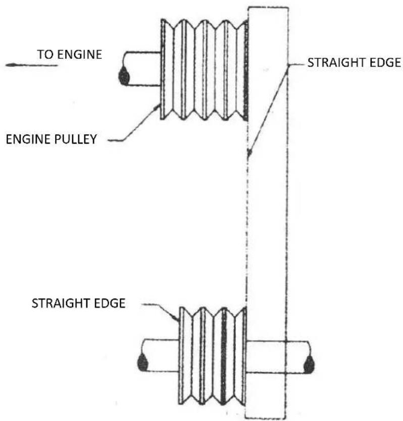
8) Misalignment will show up as a gap between the pulley face and straight edge. Make sure there is clearance between arbor pulley and saw base on both sides.
3.10 DRY CUTTING
- Never operate any saw with out safety guards in place.
- Do not exceed maximum operating speed established for blade diameter.
- Do not force blade into material: allow blade to cut at its own speed.
- Do not make long continuous cuts. Never dry cut for more than 30 seconds at a time. Allow blade to cool.
- Do not cut or grind side of blade or cut a curve or radius. Do not cut dry with blades recommended for wet cutting.
- Do not operate saw with blade diameter larger than machine's capacity.
IV. TROUBLE SHOOTING
| PROBLEM | CAUSE | REMEDY |
UNEVEN SEGMENT WEAR | (in wet cutting) insufficient water (usually on one side of blade).Equipment defects also can cause the segments to wear unevenly.Saw head is misaligned. | Flush water systemCheck flow to both sides of blade.Replace had bearings, worn arbor shaft or misalignment to spindle.Check alignment for squareness, both vertically and horizontally, of the saw blade. |
SEGMENT CRACK | Blade is too hard for material being cut | Use a blade with a softer bond / matrix. |
SEGMENT LOSS | Blade overheats because of coolant (water or air)Core is worn from undercuttingDefective collars / flanges set blade out of alignmentBlade is too hard for material being cutBlade is cutting out of round, causing a pounding motionImproper blade tension | (Wet Cutting) Check water linesMake sure flow is adequate on both sides of blade and there are no blockagesUse sufficient water to flush out the cut(Dry cutting) Run blade free of cut periodically to air coolClean collars / flanges or replace if they are under recommended diameterUse proper blade specification for material being cutReplace worn bearings; realign blade shaft or replace worn blade mounting arborWhen ordering blades match shaft speed of sawCheck spindle spindle speed to ensure blade is running at correct RPMAvoid twisting or turning blade in the cut |
CRACKS IN CORE | Blade flutters in cut as a result of losing blade tensionBlade specification is too hard for the material being cut | Tighten the blade shaft nutMake sure blade is running at proper speed and that drive pin is functioning properlyUse a softer bond / matrix to eliminate stress |
LOSS OF TENSION | Core overheatingCore overheating as a result of blade spinning on arborCore overheating from rubbing the material being cutUnequal pressure at blade clamping collars / flangesBlade is too hard for the material being cut | Make certain blade RPM is correctCheck water flow, distribution and linesTighten the blade shaft nut. Make certain the drive pin is functioningProperly align the saw to square cutCollars / flanges must be identical in diameter and the recommended sizeUse a softer bond / matrix to reduce stress |
BLADE WOBBLES | Blade is on a damaged or worn sawWorn collarBlade runs at an incorrect speedCollar / flange diameters are not identicalBlade is bent as a result of dropping or twisting | Check collars / flanges to make sure they are clean, flat and of correct diameterSet engine at proper RPMUse proper size blade collars / flangesDO NOT use bent blade. Contact blade manufacturer |
ARBOR HOLE OUT -OF- ROUND | Blade is too hard for material being cutBlade has become dullBlade does not cut material it was specified for | Select proper blade for material being cutSharpen by cutting on softer abrasive material to expose diamonds. If continually sharpening, the blade is too hard for the material being cutBreak – in on the material to be cut. If is dose not dress itself, sharpen as you would a dull blade |
UNDERCUTTINGTHE CORE | Abrasive wearing of the core faster than the segments | Use water to flush out fines generated during cuttingUse wear- resistant cores |
ARBOR HOLE OUT OF ROUND | Collars / flanges are not properly tightened, permitting blade to rotate or vibrate on the shaftCollars / flanges are worn or dirty.Blade is not properly mounted | Make certain the blade is mounted on the proper shaft diameter. Tighter the shaft nut with a wrench to make certain that the blade is secureClean collars / flanges, make sure they are not worn, Tighten arbor nutMake sure the pin bole slides over drive pin |
BLADE WORN OUT OF ROUND | Shaft bearing are wornSurges occur because engine is not properly tunedBlade arbor hole is damaged from incorrectly mounting the bladeBond / matrix is too hard for materialBlade is slipping, wearing one half of blade more than other.Check for bad bearings, bent shaft, or worn mounting arbor | Install new blade shaft bearing or blade shaft, as requiredTune engine according to manufacturer's manualIf core is worn or arbor hole damaged, DO NOT USE, Contact blade manufacturerReplace worn shaft or mounting arbor bushingMake certain that drive pin is functioningTighten spindle nut |
V. LUBRICATION AND SERVICE
- Check oil levels, wiring, hoses (air, fuel, water) and lubricate machine daily.
• Repair or replace all worn or damaged components immediately. - Check drive belt tension, do not over-tension.
• Make sure machine has full set of matched belts. - Check blade shaft, make sure arbor and threads are not worn, damaged, or bent.
- Blade shaft bearings should be tight, no free play side-to-side or up and down.
- Grease blade shaft bearings daily.
- Blade collars should be clean, free of nicks and burrs. No diameter wear and not out of round.
- Drive pin not excessively worn or bent and free of gouges.
- All guards in place and secure.
- All fasteners tight and secure.
• Air filter / oil filter (hydraulic or engine) clean. - Flush clean water through the pump and spray the assembly every night. This prolongs the pump
- and blade life.
- Clean machine before starting lubrication maintenance.
• Insure machine is on solid, level ground before starting maintenance. - During lubrication maintenance insure strict cleanliness is observed at all times.
- To avoid the risk of accidents, use the correct tool for the job and keep tools clean.
- The draining of engine oil is best carried out when the oil is warm NOT hot.
• Any spilled oil must be cleaned up immediately. - Use only clean containers for oil and only CLEAN, FRESH oils and grease of correct grade.
- Contaminated Water / Fluids / Oil / Filters Must Be Disposed of Safely.
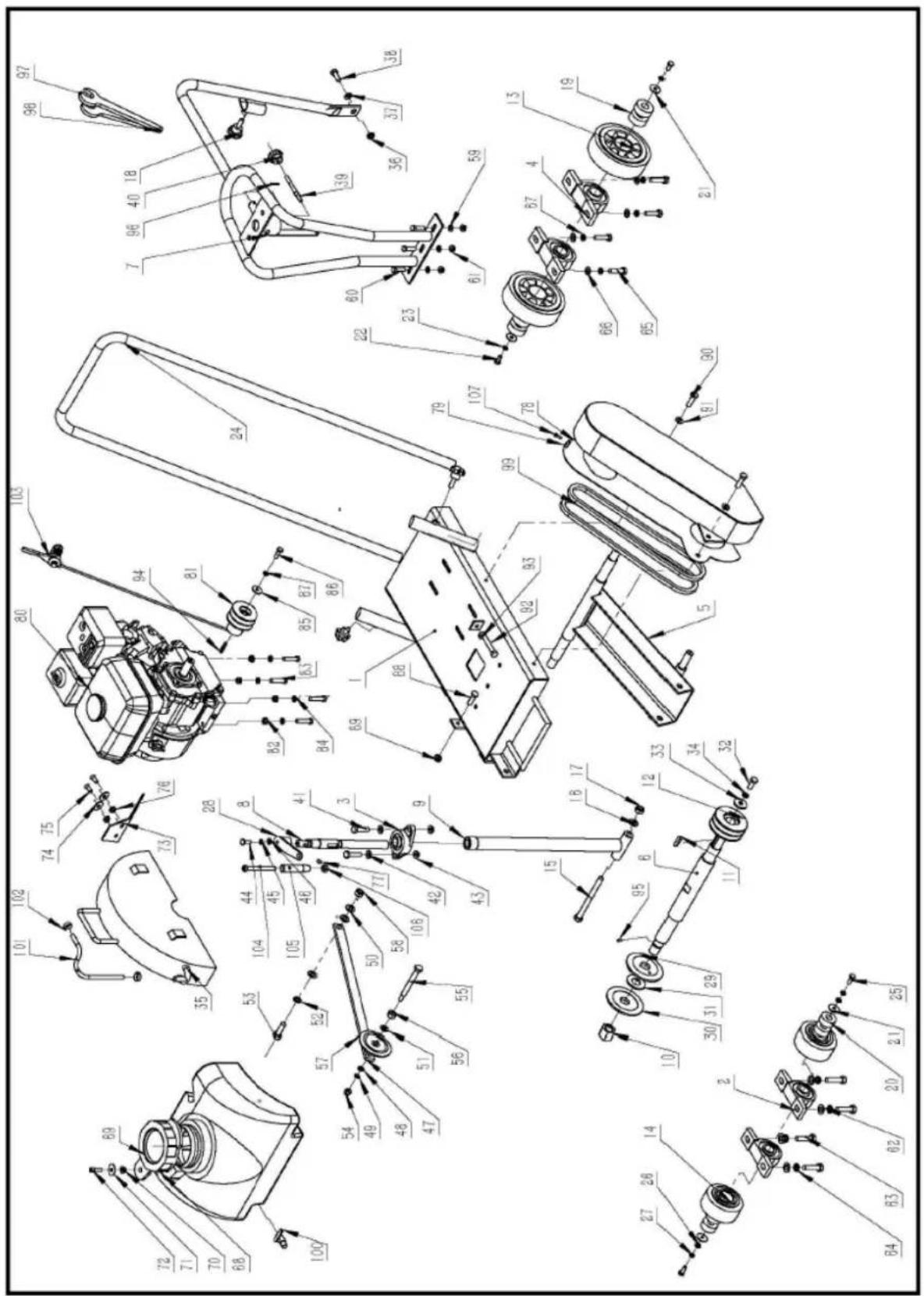
| Part No. | Description | Quantity | Part No. | Description | Quantity |
| 1 | Base Plate | 1 | 55 | Pointer Arm Screw | 1 |
| 2 | Rear Bearing Unit | 2 | 56 | Pointer Arm Nut | 1 |
| 3 | Bearing Bracket | 1 | 57 | Pointer Wheel | 1 |
| 4 | Front Bearing Unit | 2 | 58 | Locknut | 1 |
| 5 | Running Device | 1 | 59 | Flat Washer | 3 |
| 6 | Principal Axis | 1 | 60 | Hexagonal Bolt | 3 |
| 7 | Protective Frame | 1 | 61 | Nut With Washer | 3 |
| 8 | Jackscrew | 1 | 62 | Flat Washer | 4 |
| 9 | Jackpost Assy. | 1 | 63 | Hexagonal Bolt | 4 |
| 10 | Anti Tooth Nut | 1 | 64 | Spring Washer | 4 |
| 11 | Flat Key | 1 | 65 | Hexagonal Bolt | 4 |
| 12 | Pulley, Transmission | 1 | 66 | Bigger Flat Washer | 4 |
| 13 | Rear Wheel | 2 | 67 | Spring Washer | 4 |
| 14 | Front Wheel | 2 | 68 | Water Tank | 1 |
| 15 | Hexagonal Bolt | 1 | 69 | Cap, Water Tank | 1 |
| 16 | Washer | 1 | 70 | Nut with Washer | 1 |
| 17 | Locknut | 1 | 71 | Bigger Flat Washer | 1 |
| 18 | Torx Bolt | 3 | 72 | Inside Hexagonal Bolt | 1 |
| 19 | Rear Wheel Bearing | 2 | 73 | Dustproof Rubber Mat | 1 |
| 20 | Front Wheel Bearing | 2 | 74 | Flat Washer | 2 |
| 21 | Washer | 4 | 75 | Screw | 2 |
| 22 | Hexagonal Bolt | 2 | 76 | Nut with Washer | 2 |
| 23 | Cushion Ring | 2 | 77 | Screw | 1 |
| 24 | Handle | 1 | 78 | Belt Guard | 1 |
| 25 | Hexagonal Bolt | 2 | 79 | Inner Guard | 1 |
| 26 | Flat Washer | 2 | 80 | Engine | 1 |
| 27 | Spring Washer | 2 | 81 | Pulley, Engine | 1 |
| 28 | Crank Handle | 1 | 82 | Nut With Washer | 4 |
| 29 | Blade Inner Flange | 1 | 83 | Hexagonal Bolt | 4 |
| 30 | Blade Adapter | 1 | 84 | Flat Washer | 4 |
| 31 | Blade Outer Flange | 1 | 85 | Flat Washer | 1 |
| 32 | Hexagonal Bolt | 1 | 86 | Hexagonal Bolt | 1 |
| 33 | Flat Washer | 1 | 87 | Spring Washer | 1 |
| 34 | Spring Washer | 1 | 88 | Hexagonal Bolt | 1 |
| 35 | Blade Guard | 1 | 89 | Nut | 1 |
| 36 | Nut With Washer | 1 | 90 | Hexagonal Bolt | 2 |
| 37 | Bigger Flat Washer | 1 | 91 | Flat Washer | 2 |
| 38 | Hexagonal Bolt | 1 | 92 | Hexagonal Bolt | 1 |
| 39 | Lock Core | 1 | 93 | Nut | 1 |
| 40 | Screw Sleeve | 1 | 94 | Flat Washer | 1 |
| 41 | Hexagonal Bolt | 2 | 95 | Pin | 1 |
| 42 | Washer | 2 | 96 | Dowel Pin | 1 |
| 43 | Nut With Washer | 2 | 97 | Wrench | 1 |
| 44 | Hexagonal Bolt | 1 | 98 | Wrench | 1 |
| 45 | Spring Washer | 1 | 99 | Belt | 2 |
| 46 | Flat Washer | 1 | 100 | Cock | 1 |
| 47 | Pointer Arm | 1 | 101 | Water Pipe | 1 |
| 48 | Flat Washer | 1 | 102 | Clip | 2 |
| 49 | Spring Washer | 1 | 103 | Throttle Lever Assy | 1 |
| 50 | Flat Washer | 3 | 104 | Crank Handle Screw | 1 |
| 51 | Bigger Flat Washer | 1 | 105 | Crank Handle Sleeve | 1 |
| 52 | Spring Washer | 1 | 106 | Crank Handle Nut | 1 |
| 53 | Hexagonal Bolt | 1 | 107 | Hexagonal Bolt | 1 |
| 54 | Pointer Arm Nut | 1 |

| Varenr. | Beskrivelse af apparatet | Antal | Varenr. | Beskrivelse af apparatet | Antal |
| 1 | Bundplade | 1 | 55 | Skrue til pegerarm | 1 |
| 2 | Bageste lejeenhed | 2 | 56 | Møtrik til pegerarm | 1 |
| 3 | Lejebeslag | 1 | 57 | Pegehjulet | 1 |
| 4 | Forreste lejeenhed | 2 | 58 | Låsemøtrik | 1 |
| 5 | Løbende enhed | 1 | 59 | Flad skive | 3 |
| 6 | Hovedakse | 1 | 60 | Sekskantet bolt | 3 |
| 7 | Beskyttende ramme | 1 | 61 | Møtrik med skive | 3 |
| 8 | Knapskrue | 1 | 62 | Flad skive | 4 |
| 9 | Jackpost Assy. | 1 | 63 | Sekskantet bolt | 4 |
| 10 | Anti-tandmøtrik | 1 | 64 | Fjederskive | 4 |
| 11 | Flad nøgle | 1 | 65 | Sekskantet bolt | 4 |
| 12 | Remskive, transmission | 1 | 66 | Større flad skive | 4 |
| 13 | Baghjul | 2 | 67 | Fjederskive | 4 |
| 14 | Forhjul | 2 | 68 | Vandtank | 1 |
| 15 | Sekskantet bolt | 1 | 69 | Dæksel, vandtank | 1 |
| 16 | Underlagsskive | 1 | 70 | Møtrik med skive | 1 |
| 17 | Låsemøtrik | 1 | 71 | Større flad skive | 1 |
| 18 | Torx-bolt | 3 | 72 | Indvendig sekskantet bolt | 1 |
| 19 | Bageste hjulleje | 2 | 73 | Støvtæt gummimåtte | 1 |
| 20 | Forhjulsleje | 2 | 74 | Flad skive | 2 |
| 21 | Underlagsskive | 4 | 75 | Snegl | 2 |
| 22 | Sekskantet bolt | 2 | 76 | Møtrik med skive | 2 |
| 23 | Pude-ring | 2 | 77 | Snegl | 1 |
| 24 | Håndtag | 1 | 78 | Bæltebeskyttelse | 1 |
| 25 | Sekskantet bolt | 2 | 79 | Indre vagt | 1 |
| 26 | Flad skive | 2 | 80 | Motor | 1 |
| 27 | Fjederskive | 2 | 81 | Remskive, motor | 1 |
| 28 | Håndsving | 1 | 82 | Møtrik med skive | 4 |
| 29 | Bladets indre flange | 1 | 83 | Sekskantet bolt | 4 |
| 30 | Blade-adapter | 1 | 84 | Flad skive | 4 |
| 31 | Bladets ydre flange | 1 | 85 | Flad skive | 1 |
| 32 | Sekskantet bolt | 1 | 86 | Sekskantet bolt | 1 |
| 33 | Flad skive | 1 | 87 | Fjederskive | 1 |
| 34 | Fjederskive | 1 | 88 | Sekskantet bolt | 1 |
| 35 | Bladbeskyttelse | 1 | 89 | Møtrik | 1 |
| 36 | Møtrik med skive | 1 | 90 | Sekskantet bolt | 2 |
| 37 | Større flad skive | 1 | 91 | Flad skive | 2 |
| 38 | Sekskantet bolt | 1 | 92 | Sekskantet bolt | 1 |
| 39 | Lås kerne | 1 | 93 | Møtrik | 1 |
| 40 | Skruemuffe | 1 | 94 | Flad skive | 1 |
| 41 | Sekskantet bolt | 2 | 95 | Bolt | 1 |
| 42 | Underlagsskive | 2 | 96 | Dowel Pin | 1 |
| 43 | Møtrik med skive | 2 | 97 | Skruenøgle | 1 |
| 44 | Sekskantet bolt | 1 | 98 | Skruenøgle | 1 |
| 45 | Fjederskive | 1 | 99 | Rem | 2 |
| 46 | Flad skive | 1 | 100 | Hane | 1 |
| 47 | Pegearm | 1 | 101 | Vandrør | 1 |
| 48 | Flad skive | 1 | 102 | Klem | 2 |
| 49 | Fjederskive | 1 | 103 | Gashåndtag Assy | 1 |
| 50 | Flad skive | 3 | 104 | Skruen til håndsvinget | 1 |
| 51 | Større flad skive | 1 | 105 | Hylster til krumtaphåndtag | 1 |
| 52 | Fjederskive | 1 | 106 | Møtrik til håndsving | 1 |
| 53 | Sekskantet bolt | 1 | 107 | Sekskantet bolt | 1 |
| 54 | Møtrik til pegerarm | 1 |

2.5 VEDLIKEHOLDSSIKKERHET
| Del nr. | Beskrivelse | Antall | Del nr. | Beskrivelse | Antall |
| 1 | Grunnplate | 1 | 55 | Pekerarmskrue | 1 |
| 2 | Bakre lagerenhet | 2 | 56 | Pekerarmmutter | 1 |
| 3 | Lagerbrakett | 1 | 57 | Pekerhjul | 1 |
| 4 | Fremre lagerenhet | 2 | 58 | Låsemutter | 1 |
| 5 | Kjører enhet | 1 | 59 | Flat skive | 3 |
| 6 | Hovedakse | 1 | 60 | Sekskantet bolt | 3 |
| 7 | Beskyttende ramme | 1 | 61 | Mutter med skive | 3 |
| 8 | Jackskrue | 1 | 62 | Flat skive | 4 |
| 9 | Jackpost Assy. | 1 | 63 | Sekskantet bolt | 4 |
| 10 | Anti-tannmutter | 1 | 64 | Fjærskive | 4 |
| 11 | Flat nøkkel | 1 | 65 | Sekskantet bolt | 4 |
| 12 | Remskive, girkasse | 1 | 66 | Større flat vaskemaskin | 4 |
| 13 | Bakhjul | 2 | 67 | Fjærskive | 4 |
| 14 | Forhjul | 2 | 68 | Vanntank | 1 |
| 15 | Sekskantet bolt | 1 | 69 | Hette, vanntank | 1 |
| 16 | Vaskemaskin | 1 | 70 | Mutter med skive | 1 |
| 17 | Låsemutter | 1 | 71 | Større flat vaskemaskin | 1 |
| 18 | Torx bolt | 3 | 72 | Innvendig sekskantet bolt | 1 |
| 19 | Hjullager bak | 2 | 73 | Støvtett gummimatte | 1 |
| 20 | Hjullager foran | 2 | 74 | Flat skive | 2 |
| 21 | Vaskemaskin | 4 | 75 | Skrue | 2 |
| 22 | Sekskantet bolt | 2 | 76 | Mutter med skive | 2 |
| 23 | Pute Ring | 2 | 77 | Skrue | 1 |
| 24 | Håndtak | 1 | 78 | Beltevakt | 1 |
| 25 | Sekskantet bolt | 2 | 79 | Indre vakt | 1 |
| 26 | Flat skive | 2 | 80 | Motor | 1 |
| 27 | Fjærskive | 2 | 81 | Remskive, motor | 1 |
| 28 | Sveiv håndtak | 1 | 82 | Mutter med skive | 4 |
| 29 | Bladets indre flens | 1 | 83 | Sekskantet bolt | 4 |
| 30 | Bladadapter | 1 | 84 | Flat skive | 4 |
| 31 | Bladets ytre flens | 1 | 85 | Flat skive | 1 |
| 32 | Sekskantet bolt | 1 | 86 | Sekskantet bolt | 1 |
| 33 | Flat skive | 1 | 87 | Fjærskive | 1 |
| 34 | Fjærskive | 1 | 88 | Sekskantet bolt | 1 |
| 35 | Blade Guard | 1 | 89 | Mutter | 1 |
| 36 | Mutter med skive | 1 | 90 | Sekskantet bolt | 2 |
| 37 | Større flat vaskemaskin | 1 | 91 | Flat skive | 2 |
| 38 | Sekskantet bolt | 1 | 92 | Sekskantet bolt | 1 |
| 39 | Lås kjerne | 1 | 93 | Mutter | 1 |
| 40 | Skruehylse | 1 | 94 | Flat skive | 1 |
| 41 | Sekskantet bolt | 2 | 95 | Pin | 1 |
| 42 | Vaskemaskin | 2 | 96 | Dyvelpinne | 1 |
| 43 | Mutter med skive | 2 | 97 | Skiftenøkkel | 1 |
| 44 | Sekskantet bolt | 1 | 98 | Skiftenøkkel | 1 |
| 45 | Fjærskive | 1 | 99 | Reim | 2 |
| 46 | Flat skive | 1 | 100 | Hane | 1 |
| 47 | Pekerarm | 1 | 101 | Vannrør | 1 |
| 48 | Flat skive | 1 | 102 | Klipp | 2 |
| 49 | Fjærskive | 1 | 103 | Gasspak Assy | 1 |
| 50 | Flat skive | 3 | 104 | Vevhåndtaksskrue | 1 |
| 51 | Større flat vaskemaskin | 1 | 105 | Sveivhåndtakshylse | 1 |
| 52 | Fjærskive | 1 | 106 | Mutter for sveivhåndtak | 1 |
| 53 | Sekskantet bolt | 1 | 107 | Sekskantet bolt | 1 |
| 54 | Pekerarmmutter | 1 |

| Delnr. | Beskrivning | Antal | Delnr. | Beskrivning | Antal |
| 1 | Basplatta | 1 | 55 | Pekaramsskruv | 1 |
| 2 | Bakre lagerenhet | 2 | 56 | Pekarmutter | 1 |
| 3 | Lagerfäste | 1 | 57 | Pekarhjul | 1 |
| 4 | Främre lagerenhet | 2 | 58 | Låsmutter | 1 |
| 5 | Körande enhet | 1 | 59 | Platt bricka | 3 |
| 6 | Huvudaxel | 1 | 60 | Sexkantig bult | 3 |
| 7 | Skyddsram | 1 | 61 | Mutter med bricka | 3 |
| 8 | Domkraft | 1 | 62 | Platt bricka | 4 |
| 9 | Jackpost Assy. | 1 | 63 | Sexkantig bult | 4 |
| 10 | Anti-tandmutter | 1 | 64 | Fjäderbricka | 4 |
| 11 | Platt nyckel | 1 | 65 | Sexkantig bult | 4 |
| 12 | Remskiva, växellåda | 1 | 66 | Större platt bricka | 4 |
| 13 | Bakhjul | 2 | 67 | Fjäderbricka | 4 |
| 14 | Framhjul | 2 | 68 | Vattentank | 1 |
| 15 | Sexkantig bult | 1 | 69 | Lock, vattentank | 1 |
| 16 | Bricka | 1 | 70 | Mutter med bricka | 1 |
| 17 | Låsmutter | 1 | 71 | Större platt bricka | 1 |
| 18 | Torx bult | 3 | 72 | Inuti sexkantsbult | 1 |
| 19 | Bakre hjullager | 2 | 73 | Dammtät gummimatta | 1 |
| 20 | Framhjulslager | 2 | 74 | Platt bricka | 2 |
| 21 | Bricka | 4 | 75 | Gängad bult | 2 |
| 22 | Sexkantig bult | 2 | 76 | Mutter med bricka | 2 |
| 23 | Kuddring | 2 | 77 | Gängad bult | 1 |
| 24 | Handtag | 1 | 78 | Bältesskydd | 1 |
| 25 | Sexkantig bult | 2 | 79 | Inre vakt | 1 |
| 26 | Platt bricka | 2 | 80 | Motor | 1 |
| 27 | Fjäderbricka | 2 | 81 | Remskiva, motor | 1 |
| 28 | Vevhandtag | 1 | 82 | Mutter med bricka | 4 |
| 29 | Bladets inre fläns | 1 | 83 | Sexkantig bult | 4 |
| 30 | Bladadapter | 1 | 84 | Platt bricka | 4 |
| 31 | Bladets yttre fläns | 1 | 85 | Platt bricka | 1 |
| 32 | Sexkantig bult | 1 | 86 | Sexkantig bult | 1 |
| 33 | Platt bricka | 1 | 87 | Fjäderbricka | 1 |
| 34 | Fjäderbricka | 1 | 88 | Sexkantig bult | 1 |
| 35 | Bladskydd | 1 | 89 | Mutter | 1 |
| 36 | Mutter med bricka | 1 | 90 | Sexkantig bult | 2 |
| 37 | Större platt bricka | 1 | 91 | Platt bricka | 2 |
| 38 | Sexkantig bult | 1 | 92 | Sexkantig bult | 1 |
| 39 | Lås kärna | 1 | 93 | Mutter | 1 |
| 40 | Skruvhylsa | 1 | 94 | Platt bricka | 1 |
| 41 | Sexkantig bult | 2 | 95 | Stift | 1 |
| 42 | Bricka | 2 | 96 | Dowel Pin | 1 |
| 43 | Mutter med bricka | 2 | 97 | Rycka | 1 |
| 44 | Sexkantig bult | 1 | 98 | Rycka | 1 |
| 45 | Fjäderbricka | 1 | 99 | Rem | 2 |
| 46 | Platt bricka | 1 | 100 | Kuk | 1 |
| 47 | Pekararm | 1 | 101 | Vattenrör | 1 |
| 48 | Platt bricka | 1 | 102 | Klämma | 2 |
| 49 | Fjäderbricka | 1 | 103 | Gasspak Assy | 1 |
| 50 | Platt bricka | 3 | 104 | Vevhandtagsskruv | 1 |
| 51 | Större platt bricka | 1 | 105 | Vevhandtagshylsa | 1 |
| 52 | Fjäderbricka | 1 | 106 | Vevhandtagsmutter | 1 |
| 53 | Sexkantig bult | 1 | 107 | Sexkantig bult | 1 |
| 54 | Pekarmutter | 1 |