FS-500 - Electric saw MSW - Free user manual and instructions
Find the device manual for free FS-500 MSW in PDF.

User questions about FS-500 MSW
0 question about this device. Answer the ones you know or ask your own.
Ask a new question about this device
Download the instructions for your Electric saw in PDF format for free! Find your manual FS-500 - MSW and take your electronic device back in hand. On this page are published all the documents necessary for the use of your device. FS-500 by MSW.
USER MANUAL FS-500 MSW
MOTOR
- MSW-F5-500
natural_image
Mechanical diagram showing a tool interacting with a component, no text or symbols presentnatural_image
Technical line drawing of a mechanical assembly with no visible text or symbolsTECHNICAL DATA e) Only the manufacturer's service centre@demunake
| Parameter description Parameter value | ||
| Product name FLOOR SAW | ||
| Model | MSW-FS-350 | MSW-FS-500 |
| Engine displacement (cm2) | 270 | |
| Maximum power (hp at rpm) | 9/3600 | |
| Dimensions [Width x Depth x HOLT mm] | 547x1518x1055 | |
| Weight (kg) 74 | ||
| Saw blade maximum diameter (mm) | 350 | |
| Maximum cutting depth (mm) | 140 | |
| Water tank capacity (L) 25 | ||
| Fuel tank capacity (L) 6 | ||
| Lubrication system capacity (L) | -1,1 | |
| Spark plug type F/RTC (gap 0,7-0,8 mm) | ||
| Drive bolt type P(660/260) | ||
| Fuel consumption (L/k) ∅:1.4 | ||
| Acoustic pressure level LpA [dB(A)] | 89.48 | |
| Sound power level LWA [dB(A)] | 112 | |
- GENERAL DESCRIPTION
The user manual is designed to assist in the safe and trouble free use of the device. The product is designed and manufactured in accordance with strict technical guidelines, using state-of-the-art technologies and components. Additionally, it is produced in compliance with the most stringent quality standards.
DO NOT USE THE DEVICE UNLESS YOU HAVE THOROUGHLY READ AND UNDERSTOOD THIS USER MANUAL.
To increase the product life of the device and to ensure trouble free operation, use it in accordance with this user manual and regularly perform maintenance tasks. The technical data and specifications in this user manual are up to date. The manufacturer reserves the right to make changes associated with quality improvement. The device is designed to reduce noise emission risks to a minimum, taking into account technological progress and noise reduction opportunities.
| CE | The product satisfies the relevant safety standards. |
| Read instructions before use. | |
| The product must be recycled. | |
| WARNING or CAUTION! or REMEMBER! Applicable to the given situation. (general warning sign) | |
| Use ear protection. Exposure to loud noise may result in hearing loss. | |
| Wear protective goggles. | |
| Wear a dust mask (respiratory tract protection). | |
| Wear protective gloves. | |
| Wear face protection. | |
| Wear a face shield. | |
| Use an adjustable guard. | |
| Wear protective clothing. | |
| Emergency stop! | |
| ATTENTION! Hot surface, risk of burns! | |
| Do not smoke near the device. The device contains flammable substances. |
PLEASE NOTE! Drawings in this manual are for illustration purposes only and in some details may differ from the actual product.
The original operation manual is written in German. Other language versions are translations from the German.
- USAGE SAFETY
ATTENTION! Read all safety warnings and all instructions. Failure to follow the warnings and instructions may result in electric shock, fire and/or serious injury or even death.
The terms "device" or "product" are used in the warnings and instructions to refer to FLOOR SAW.
2.1. SAFETY IN THE WORKPLACE
a) Make sure the workplace is clean and well lit. A messy or poorly lit workplace may lead to accidents. Try to think ahead, observe what is going on and use common sense when working with the device.
b) Do not use the device in a potentially explosive environment, for example in the presence of flammable liquids, gases or dust. The device generates sparks which may ignite dust or fumes.
c) If you discover damage or irregular operation, immediately switch the device off and report it to a supervisor without delay.
d) If you are unsure about whether the product is operating correctly or if you find damage, please contact the manufacturer's service centre.
repairs to the product. Do not attempt to make repairs yourself!
f) Only the manufacturer's service point may repair the device. Do not attempt any repairs independently!
g) In case of fire, use a powder or carbon dioxide (CO2) fire extinguisher (one intended for use on live electrical devices) to put it out.
h) Children or unauthorised persons are forbidden to enter a work station. (A distinction may result in loss of control over the device).
i) Use the device in a well-ventilated space.
j) The device produces dust and debris during operation. It is important to protect bystanders from their harmful effects.
k) Regularly inspect the condition of the safety labels. If the labels are illegible, they must be replaced.
1) Please keep this manual available for future reference. If this device is passed on to a third party, the manual must be passed on with it.
m) Keep packaging elements and small assembly parts in a place not available to children.
n) Keep the device away from children and animals.
c) If this device is used together with another equipment, the remaining instructions for use shall also be followed.
p) Consider the work area environment before starting to work. Don't expose power tools to rain or wet soil. Don't use power tools in damp or wet locations. The work area should be well secured. Don't use the tool in the presence of flammable liquids or gases. Power tools produce sparks during normal operation or when switching ON/OFF. Never use power tools in dangerous sites containing lacquet, paint, benzene, thinner, gasoline, gases, adhesive agents, and other materials which are combustible or explosive.
REMEMBERI When using the device, protect children and other bystanders.
2.2. PERSONAL SAFETY
a) Do not use the device when tired, ill or under the influence of alcohol, narcotics or medication which can significantly impair the ability to operate the device.
b) The machine may be operated by physically fit persons who are able to handle the machine, are properly trained, who have reviewed this operating manual and have received training in occupational health and safety.
c) When working with the device, use common sense and stay alert. Temporary loss of concentration while using the device may lead to serious injuries.
d) Use personal protective equipment as required for working with the device, specified in section 1 (Legend).
The use of correct and approved personal protective equipment reduces the risk of injury.
c) To prevent the device from accidentally switching on, make sure the switch is on the OFF position before connecting to a power source.
Do not overestimate your abilities. When using the device, keep your balance and remain stable at all times. This will ensure better control over the device in unexpected situations.
g) Do not wear loose clothing or jewellery. Keep hair, clothes and gloves away from moving parts. Loose clothing, jewellery or long hair may get caught in moving parts.
h) Use eye, ear and respiratory protection.
i) The device is not a toy. Children must be supervised to ensure that they do not play with the device.
j) Do not put your hands or other items inside the device while it is in use!
2.3.SAFE DEVICE USE
a) Do not overload the device. Use the appropriate tools for the given task. A correctly-selected device will perform the task for which it was designed better and in a safer manner.
b) Do not use the device if the ON/OFF switch does not function properly (does not switch the device on and off). Devices which cannot be switched on and off using the ON/OFF switch are hazardous, should not be operated and must be repaired.
c) Make sure the plug is disconnected from the socket before attempting any adjustments, accessory replacements or before putting the device aside. Such precautions will reduce the risk of accidentally activating the device.
d) When not in use, store in a safe place, away from children and people not familiar with the device who have not read the user manual. The device may pose a hazard in the hands of inexperienced users.
c) Keep the device in perfect technical condition. Before each use check for general damage and especially check for cracked parts or elements and for any other conditions which may impact the safe operation of the device. If damage is discovered, hand over the device for repair before use.
fi Keep the device out of the reach of children.
g) Device repair or maintenance should be carried out by qualified persons, only using original spare parts. This will ensure safe use.
h) To ensure the operational integrity of the device, do not remove factory-fitted guards and do not loosen any screws.
When transporting and handling the device between the warehouse and the destination, observe the occupational health and safety principles for manual transport operations which apply in the country where the device will be used.
b Avoid situations where the device stops working during use due to excessive loading. This may result in overheating of the drive elements and damage to the device.
k) Do not touch articulated parts or accessories unless the device has been disconnected from the power source.
Do not leave this appliance unattended while it is in use.
m). Clean the device regularly to prevent stubborn grime from accumulating.
n) The specified vibrations emission was measured using standard measurement methods. Vibrations emissions may change if the device is used in different surroundings.
a) It is forbidden to interfere with the structure of the device in order to change its parameters or construction.
p) Keep the device away from sources of fire and heat.
EN
EN
q) Do not cover the ventilation openings!
r) Oil leaking from the machine should be reported to the appropriate services or comply with legal requirements applicable in the area of use.
s) Danger! Danger to health and the risk of explosion of the internal combustion engine.
t) Poisonous carbon monoxide is present in the engine exhaust. Remaining in a carbon monoxide environment may lead to losing consciousness or even death. Do not run the engine in a closed space.
u; Protect the engine from heat, sparks and flame. Do not smoke in the vicinity of the engine!
v) Petrol is flammable and explosive. Before refuelling the engine should be turned off and cooled down
w) Warning: Risk of engine damage due to wrong fuel
ATTENTION! Despite the safe design of the device and its protective features, and despite the use of additional elements protecting the operator, there is still a slight risk of accident or injury when using the device. Stay alert and use common sense when using the device.
- USE GUIDELINES
The product is intended for making straight cuts in hard surfaces, such as concrete (also reinforced), asphalt, etc., as well as for making expansion joints in pavements.
The user is liable for any damage resulting from unintended use of the device.
3.1. DEVICE DESCRIPTION MSW FS 350
MSW-FS-500
A. Height adjustment knob
B. Control Panel
C. Handle
D. Water connection with inlet valve
E. Water tank
F. Fuel tank
G. Saw blade guard
H. Cutting line guide
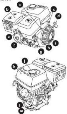
ENGINE
a) Throttle Lever (for MSW-FS-500 on the control panel)
b) Silencer
c) Ignition switch
d) Starter cord
h! Manual choke lever
• ON - switched on/choke
- OFF - off/valve open
i) Starter
j) Fuel tank cap
k) Fuel tank
1 Oil drain plug
m) Oil filler/level cap
3.2. PREPARING FOR USE
APPLIANCE LOCATION
Keep the device away from any hot surfaces. The machine should always be used on an even, stable, fireproof surface and out of reach of children and people with reduced psychological, sensory and mental functions. The valve that disables the compressed air supply should be immediately accessible from the area where the device is being used. Make sure that the pressure of the air supplying the device does not exceed the recommended range.
ASSEMBLING THE APPLIANCE
MSW-F5-350
To adjust the handles to the operator's preferred position, loosen the adjustment levers (13 and 14).
c) Spark plug
3 Air filter housing
g) Fuel valve lever
- ON - valve-inflow open
- OFF - valve-inflow closed
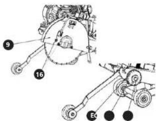
To fit the cutting disc, make sure the machine's engine is turned off (ignition switch is OFF). Set the machine to the highest cutting position, then unscrew the screw securing the blade guard (16) and remove the guard (9). Unscrew the saw blade clamping bolt (D, right-hand thread) and fix the saw blade by keeping it stationary and tightening the clamping bolt (D) again. Pay attention to the arrow on the blade guard showing the direction of rotation of the blade while the machine is running. When firing/replacing the saw blade, check that the mounting flanges (C and E) are undamaged. Replicate the saw blade guard (3) and tighten its screw (16). Make sure that the cutting disc is aligned with the cutting line guide (7) - if not, align it by adjusting the guide.
1 Shifter
2 Ignition switch
3 Height adjustment knob
4 Cutting depth scale
5. Fuel tank
6 Oil drain plug
7 Cutting line guide
B Belt cover
9 Saw blade guard
10 Space for the service key
11. Water connection
12 Hook for lifting the entire machine
13 Adjustment lever
14 Adjustment lever
15 Water supply valve
16 Bolt securing the saw blade guard
17. Water tank (not shown in the picture
located above the lifting hook)
MSW FS 500
Make sure the unit is turned off (ignition switch is OFF). Unscrew the cutter blade nut and remove the outer flange holding it. The surface of the flange in contact with the blade should be clean. Place the cutting disc on the axle, paying attention to its direction in accordance with the direction of rotation of the machine drive. Place the collar holding the shield and the washer with the part sunk inwards (towards the shield - see the picture below), and tighten them with a nut.

PLEASE NOTE: use diamond blades adapted to working with rotations higher than the maximum rotation of the machine (see technical parameters tables) and adapted to water cooling. When transporting the machine, the cutting disc must be removed.
- Engine oil
PLEASE NOTE: before starting the machine for the first time, the engine oil should be topped up, as the machine is empty during transport.
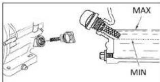
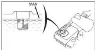
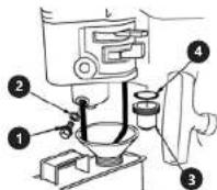
Always check the oil with the machine turned off and the engine cold, or at least 5 minutes after the engine is turned off. The machine should be placed in a horizontal position, i.e. not tilted, on a flat, even surface. Unscrew the oil filler cap and wipe clean its end which enters the hole, making sure that no foreign objects get into the hole in the meantime. Then, put the plug in the hole (without screwing it in) and takes it out after a few seconds, checking the oil level at the plug tip. The engine oil should be in the range of the marked part of the tip, i.e. between the "MAX" and "MIN" levels (see image below). If it is not, top the oil up to the bottom edge of the filler hole, and then check the level at the tip of the plug again. Never exceed the maximum level and never allow its level to drop below the minimum – there is a danger of damaging the engine when it is running! Recommended oil: SAE 10W30 for diesel 4-stroke engines (standard operating conditions) or SW30 (operation also in very cold weather), API SJ class or newer.
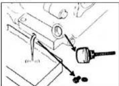
The machine must be turned off while the engine oil is replaced. Hot oil is thinner and drains faster, however, if you want to change the oil right after the machine stopped running, let it cool down (for several minutes).
PLEASE NOTE: the hot oil and its drainage area may be hot—beware of burns! (see picture below)
Place an oil-resistant vessel of appropriate capacity under the drain plug, then unscrow the oil inlet plug first, and then the drain plug and wait until the oil flows out completely. Before replacing the drain plug, wipe off the oily area around the engine housing as well as its thread. Tighten the plug gently, do not tighten it as far as it will go, so as not to crush its gasket - it may lose its tightness. If the drain plug gasket is damaged/worn, it must be replaced. Pour fresh oil through the filler plug to the correct level (see the previous paragraph). Close the filler opening with the plug.
natural_image
Mechanical assembly diagram showing a tool interacting with a bracket and a screwdriver (no text or symbols visible)- Fuel
PLEASE NOTE: you can refuel only with the engine off, in a well-ventilated area, and away from sources of fire or sparks which might potentially cause the fuel or its vapours to ignite! When refuelling the machine, make sure not to spill fuel on the hot parts.
Unscrew the cap on the top of the fuel tank and pour the fuel, not exceeding the maximum level, i.e. to the limit of the neck of the strainer in the tank inlet (see the picture below). To power the machine, use only unleaded petrol (min. 95 RON octans) with ethanol/methanol content not exceeding 5%. Fuel with the addition of methanol must contain additives: co-solvents and corrosion inhibitors. It is not allowed to use an oil/fuel mixture!
3.3. DEVICE USE
A. Starting the machine
Open the fuel supply valve - switch the lever ON. With a cold engine, move the hand choke lever to ON (the valve is closed). If the engine is warm, leave the choke lever in the OFF position (the valve is open). Set the throttle lever to 1/3 of the scale length from the slowest revolutions, i.e. at the turtle icon (in the case of the MSW-F5-500 model, the throttle lever is located on the machine control panel). Set the ignition switch to ON. Pull the starter cord - pull it gently until you feel resistance, then pull firmly until the engine starts (it may require several repetitions). After the engine has started, do not let go of the cord, but let it return slowly to its original position. When starting cold, let the engine idle first in order to bring it up to operating temperature - as the temperature rises, gradually reduce choke by moving the choke lever to the OFF position (the valve is open).
PLEASE NOTE: the water supply should be shut off while the engine is warming up.
B. Cutting
Mark a straight line on the floor/pavement along which you are going to cut.
In the MSW FS-350, start the engine with the cutting blade raised. Turn on the water supply, increase the engine speed to maximum.
Use the height adjustment knob to position the saw blade so that it is in contact with the ground. Set the desired cutting depth - each graduation of the scale corresponds to 9.5 mm (3/8 inch). Lower the cutting disc slowly towards the surface to be cut so as not to stall the engine. Make a rough cut to a depth of 50 mm before reaching the desired cutting depth - it is the so-called gradual cut. Slowly move the machine forward, making sure that the guide blade is following the marked line.
In the MSW-FS-500 model, in order to start cutting set the maximum revolutions, and then lower the blade to the desired cutting depth. Then, fix the desired cutting depth using the height adjustment knob, and lock it with the lever under the knob. Turn on the water supply, lower the blade slowly, and proceed to make the cut with maximum engine speed. Slowly move the machine forward, making sure that the guide blade is following the marked line. If the cutting disc will not keep in the groove, reduce the speed with which the machine is moved forward.
C. Turning the machine off
Emergency shutdown - in an emergency, press the emergency shutdown button on the left handlebar (MSW-FS-350) or the red poppet on the control panel (MSW-FS-500), the engine will stop immediately. Close the water supply.
- Normal shutdown - stop cutting and turn-off water supply. Move the throttle lever to the lowest speed (the turtle icon) and let the machine run for a few minutes. Then turn the ignition switch to the OFF position. Close the fuel supply valve - the OFF position.
D. Automatic shutdown of the machine
There may be several reasons why the machine will
stop running unexpectedly:
- Wrong belt tension
No fuel
• The machine is pushed forward too fast or the blade is lowered too rapidly
In each of these cases, first release the blade from the groove, turn off the machine (the switch in the OFF position). turn off the water supply and check the machine carefully for damage before continuing work.
3.4. CLEANING AND MAINTENANCE
a) Unplug the mains plug and allow the device to cool completely before each cleaning, adjustment or replacement of accessories, or if the device is not being used. Wait for the rotating elements to stop.
b) Use only non-corrosive cleaners to clean the surface. c) Store the unit in a dry, cool place, free from moisture and direct exposure to sunlight.
d) Do not spray the device with a water jet or submerge it in water.
c) Do not allow water to get inside the device through vents in the housing of the device.
1) Clean the vents with a brush and compressed air.
g) The device must be regularly inspected to check its technical efficiency and spot any damage.
h) Use a soft cloth for cleaning.
- Use a soft, damp cloth for cleaning. - Do not use sharp and/or metal objects for cleaning (e.g. a wire brush or a metal spatula) because they may damage the surface material of the appliance.
k) Check the engine oil level after each use, and top up the bearing oil to the height adjustment mechanism.
l) When the machine is not used for a long time, it is recommended to drain the fuel (for more details, see 3.4.1 point F)
3.4.1 MAINTENANCE INTERVALS
| Regular service interval - whichever comes List | After each use | In the first month or after 20 hours of operation | Every 3 months or after every 50 hours of operation | Every 6 months or 100 hours of operation | Every year or 300 hours of operation | |
| Component | ||||||
| Engine oil | Level check √ | |||||
| Replacement √ √ | ||||||
| Air filter | Check √ | |||||
| Cleaning √ (1) | ||||||
| Replacement √ | ||||||
| Sedimentation like | Cleaning √ | |||||
| Spark plug | Check/Cleaning √ | |||||
| Replacement √ | ||||||
| Idle speed | Cleaning possibly adjustment | √ | ||||
| Valve clearances | Cleaning - possibly adjustment | √ | ||||
| Fuel tank with strainer | Cleaning | √ | ||||
| Combustion chamber | Every 300 hours of operation [2] | |||||
| Fuel lines Every 2 years (if needed replace) (2) | ||||||
| (1) - when working in a dusty environment, more frequent service intervals are recommended | ||||||
| (2) - required specialized tools and knowledge - recommended to be commissioned by a professional service | ||||||
| Valve clearance (cold): intake valve 0.15 ± 0.02mm/exhaust valve 0.20 ± 0.02mm | ||||||
A. Air filter replacement
The engine of the machine is equipped with a 2-element air filter consisting of a sponge filter and a paper filter (see the picture below).
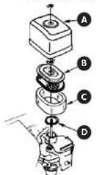
A. Air traffic
B. Paper air filter
C. Sponge air filter
D. Gasket
To get to the air 1ter, unscrew the wing screw on the top of the 1ter case and remove the case. Then, unscrew another wing screw to disassemble the 2-element 1ter. After removing the 1ter, remove the sponge element. Check the condition of both 1ters, decide whether they need to be replaced (see maintenance interval table), or whether they can be reused after cleaning. If the 1ters are reusable:
- Paper filter - shake of loose debris, then blow using compressed air (pressure not greater than 2 Bar/207 kPa/30 psi) from the outlet side, i.e. the side where the engine socks the filtered air into the carburetor. PLEASE, NOTE: never wipe the filter with a brush because it causes debris to penetrate the filter structure!
- Sponge filter - soak in warm water with the addition of grey soap, then rinse under running water and allow to dry completely. Alternatively, you can soak the sponge filter in non-cammable solvent and allow it to dry completely.) Dip the clean and completely dry filter in fresh engine oil (the same type as the machine engine), and, after removing it, squeeze out excess oil well, otherwise it will disturb the operation of the engine - it will excise smoke. Before installing a clean filter, use a damp, light-free cloth to wipe the case and the base of the filter case, making that no dirt or water gets into the carburettor air doors. Then, place the sponge filter onto the paper filter and install it in the reverse order of disassembly, remembering about the gasket under the filter. Tighten both the filter and its raw security with a wing screw.
B. Cleaning the sedimentation line
CAUTION: Perform this procedure on a cold engine! Close the fuel supply valve and dismantle the sedimentation filter and its gasket. Wash both parts in non-formmable solvent, then dry them. When drs, place the gasket on the fuel valve and tighten the sedimentation filter again. Open the fuel supply valve and check for fuel leaks around the filter - if there are any, remove the filter and replace the gasket.
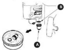
A. Sedimentation filter
B. Gasket
A. Replacing the spark plug
PLEASE NOTE: When you remove the spark plug, the engine must be turned it, and could. Tightening it too lightly/too much, or the wrong type of spark plug, or a break in the electrode can damage the engine. Turn the ignition switch to OFF. Remove the ignition cable cap from the spark plug. Remove the spark plug from the engine. Check the condition of the spark plug - in the case of a burnt-out electrode, cracked or chipped insulation (ceramics), it must be replaced. When the spark plug is it for further use, check the electrode gap before putting it back and adjust if necessary, the same with a new plug. The re-used spark plug should be screwed in by tightening 1/8-1/4 turn of the key, and a new plug by ½ turn.
B. Idle speed control
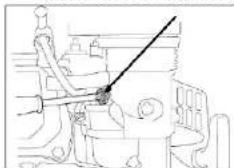
PLEASE NOTE: the machine has a factory set idle speed, and the speed should not be changed! Idle speed adjustment is performed only in case of engine or engine components repair, which requires specialized tools. Start the engine and allow it to warm up to the operating temperature. Then, set the throttle lever to the slowest speed and adjust the idle speed with the throttle lock screw (see the picture below). Their value should be 1800 ± 50 revolutions per minute.
natural_image
Technical line drawing of a mechanical assembly with no visible text or symbolsC. Drive belt tension adjustment
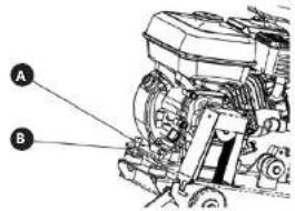
MSW-15-350: After several uses of the machine, it may be necessary to adjust the tension of the drive belt. To do this, loosen (but do not unscrew) the 2 screws securing the engine to the frame of the machine (picture below - A) and tighten the adjusting nuts (B), and the loosened bolts will raise the engine. If the belt tension is correct, retighten the A bolts.
MSW-FS-500: Remove the screws securing the blade guard. Check that the belt and tensioning rollers are uniformly parallel - e.g. apply a straight edge or engineering square to the tensioning rollers and, if necessary, adjust them so that the line is even.
PLEASE NOTE: the belt, both loose and too tight, has a negative impact on the operation and performance of the machine, and may even damage the cutter.
D. Storage and fuel
If the machine is not used for a long time, it is recommended to drain the fuel. The fuel that is no longer used tends to oxidize and begins to lose its properties which has a negative influence on the machine itself. Typical symptoms of lowered properties of the fuel in the machine are problems with starting and/or deposits blocking the fuel system, affecting the machine performance. The period of keeping usable fuel in the tank depends not only on the ambient temperature or the amount of fuel in the tank, but also on the quality of the fuel itself.
- Draining the fuel. Having made sure that the fuel supply valve is closed, place a petrol-resistant vessel with a funnel (e.g., a canister) under the carburettor. Unscrew the carburettor drain screw and the sedimentation filter. Then, open the fuel supply valve and wait until all the fuel has been drained. Screw in the carburettor drain plug on again, remembering about the washer and sedimentation filter and the gasket.
-
Carburetter drain plug
-
Drain plug washer
-
Sedimentation filter
-
Sedimentation filter gasket
- Fuel additive - an alternative method of extending the fuel viability for the machine is adding the so-called fuel stabilizer. Fuel stabilizers are commonly available petrochemicals added to fuel. When adding a stabilizer to the fuel, follow the manufacturer's recommendations. Fill the tank with fresh fuel and add the stabilizer. Then, start the machine and let it run idle for 10 minutes. Turn off the engine and close the fuel valve.
E. Storage of the unused machine for a longer period of time.
If it is necessary to store the machine unused for a
longer period of time, replace the engine oil, then unscrew the spark plug and pour 5 10 ml of fresh engine oil through the hole in the engine. Pull the starter cord several times to distribute the oil in the cylinder. Screw the spark plug back in, then grasp the starter cord and pull it slowly until you feel resistance. Then, slowly let the starter cord return to its original position - this will close the valves in the cylinder and prevent spreading moisture. Drain the fuel or top up the stabilizer (see the previous point) - close the fuel supply valve. Cover the (cold) machine with a cloth or other breathable material to protect it from dust. The procedure for starting the machine after storing it for a very long time is similar to starting the machine for the first time.
PLEASE NOTE: sealing materials, impermeable to air.
such as foil, etc. cause moisture accumulation which may lead to corrosion of the machine!
DISPOSING OF USED DEVICES
Do not dispose of this device in municipal waste systems. Hand it over to an electric and electrical device recycling and collection point. Check the symbol on the product instruction manual and packaging. The plastics used to construct the device can be recycled in accordance with their markings. By choosing to recycle you are making a significant contribution to the protection of our environment.
Contact local authorities for information on your local recycling facility.
DANE TECHNICZNE
2.1. BEZPIECZEŃSTWO W MIEJSCU PRACY
MSW-FS-500
• Paliwo
natural_image
Technical line drawing of a mechanical assembly with no visible text or symbolsMSW-F5-500
natural_image
Illustration of a hand using a tool to adjust or install a mechanical component (no text or symbols visible)Palivo
natural_image
Technical line drawing of a mechanical assembly with no visible text or symbolsE. Nastaveni napnuti hnaciho femene
MSW-FS-500
natural_image
Mechanical assembly diagram showing a tool interacting with a bracket and a magnifying glass (no text or symbols visible)Carburant
natural_image
Technical line drawing of a mechanical assembly with no visible text or symbolsMSW FS 500
natural_image
Technical line drawing of a mechanical assembly with no visible text or symbolsMSW-FS-500
natural_image
Mechanical assembly diagram showing a tool interacting with a bracket and a screwdriver (no text or symbols visible)- Combustible
natural_image
Technical line drawing of a mechanical assembly with no visible text or symbols

| DE | Beschreibung EN | Description | Anzahl | Number of pieces | ||
| 1 MBx16 Schraube MBx16 screw 1 | |||
| 2 Flache Unterlegscheibe ø8 ø8 Flat washer 1 | |||
| 3 Handrad Handwheel 1 | |||
| 4 Hebestange Lifting bar 1 | |||
| 5 Einbauabdeckung des Griffs Handle mounting cover 1 | |||
| 6 Basis für die Montage des Griffs. Handle mounting base 1 | |||
| 7 | Griff mit Hebel und Stoppschalter | Handle with levers and stop button | 1 |
| 8 Gummlunterlage Rubber pad | 2 | ||
| 9 Gelandergriff zum Anheben Lifting handle 1 | |||
| 10 | Propellermutter | Drive nut | 1 |
| 11 | Luftfeder | Air spring | 1 |
| 12 | Propellermutter | Drive bolt | 1 |
| 13 | Hintores Rad | Rear wheel | 2 |
| 14 | Lagor 6204 | Boaring 6204 | 4 |
| 15 | Flache Unterlegscheibe ø10 | Flat washer ø10 | 2 |
| 16 | Federscheibe ø10 | ø10 Spring washer | 2 |
| 17 | Schraube M10x20 | Screw M10x20 | 2 |
| 18 | Kreisring | Circle link | 1 |
| 19 | Indikator | Indicator | 1 |
| 20 | Zeitsensor | Dial gauge | 1 |
| 21 | Schraube M10x70 | Screw M10x70 | 2 |
| 22 | Unterlegscheibe ø50x3 | Flat washer ø50x3 2 | |
| 23 | Federscheibe A | Spring washer A | 2 |
| 24 | Zugelement Tensile element | 2 | |
| 25 | Gummiunterlegscheibe B | Rubber pad B | 2 |
| 26 | Unterlegscheibe ø10 | Flat washer ø10 | 2 |
| 27 | Federscheibe ø10 | Spring washer ø10 | 2 |
| 28 | Mutter M10 | Nut M10 | 2 |
| 29 | Motorhalterungsplatte | Engine mounting plate | 1 |
| 30 | Mutter M10 | Nut M10 | 6 |
| 31 | Gummiunterlegscheibe | Rubber pad | 2 |
| 32 | Maschinenbasis | Machine base | 1 |
| 33 | Antriebsachse des rechten Rads | Right wheel drive shaft | 1 |
| 34 | Radlachsführungen | Wheel shaft guides | 2 |
| 35 | Antriebsachse des linken Rades | Left wheel drive shaft | 1 |
| 36 | Mutter M10 | Nut: M10 | 1 |
| 37 | Flache Unterlegscheibe ø10 | Flat washer ø10 | 1 |
| 38 | Federscheibe ø10 | Spring washer ø10 | 1 |
| 39 | Schraube M10x30 | Screw M10x30 | 1 |
| 40 | Schraube M10x70 | Screw M10x70 | 1 |
| 41 | Mutter M10 | Nut: M10 | 1 |
| 42 | Rahmen | Frame | 1 |
| 43 | Schraube M10x70 | Screw M10x70 | 1 |
| 44 | Lager 6001 | Bearing 6001 | 2 |
| 45 | Führungsrad | Guide pulley | 1 |
| 46 | Führungsgaradhülse | Guide pin bush | 1 |
| 47 | Radstange Wheel rod | 1 | |
| 48 | Radscheibe | Wheel washer | 1 |
| 49 | Mutter M10 | Nut: M10 | 1 |
| 50 | Schraube M10x20 | Screw M10x20 | 2 |
| 51 | Federscheibe ø10 | Spring washer ø10 | 2 |
| 52 | Flache Unterlegscheibe ø10 | Flat washer ø10 | 2 |
| 53 | Lager 6204 | Bearing 6204 | 4 |
| 54 | Vorderrad | Front wheel | 2 |
| 55 | Staubschutzblende | Dust cap | 1 |
| 56 | Kreising | Circle link | 1 |
| 57 | Lager 6204 | Bearing 6204 | 2 |
| 58 | Lagordeckel Bearing cover | 1 | |
| 59 | Schneidscheibenspindel | Blade spindle | 1 |
| 60 | Spindelrolle | Spindle roll 1 | |
| 61 | Klemme B des der Schneidscheibe | Clamp B of the saw blade | 1 |
| 62 | Schneidscheibe | Cutting disc | 1 |
| 63 | Klemme A des der Schneidscheibe | Clamp A of the saw blade | 1 |
| 64 | Wasserbehälter | Water tank | 1 |
| 65 | Wassortank Montagerahmen | Water tank mounting frame | 1 |
| 66 | Motor | Engine | 1 |
| 67 | Riomenrolle | Belt roller | 1 |
| 68 | Riemengurtolabdeckung | Belt cover | 1 |
| 69 | Kabelklemme | Cable clamp | 2 |
| 70 | Schutzabdeckung A für die Trennscheibe | Guard A for the cutting disc | 1 |
| 71 | Verbindungselement | Connecting piece | 1 |
| 72 | Schutzabdeckung B für die Trennscheibe | Guard B for the cutting disc | 1 |


| DE | Beschreibung EN | Description | Anzahl Number of pieces | ||
| 1 Griffhalterung Handle attachment 1 | |||
| 2 Steuempanel Control panel 1 | |||
| 3 Hebegriff Lifting handle 1 | |||
| 4 Tiefenwahl Einstellknopf Depth dial 1 | |||
| 5 Lager Bearing 1 | |||
| 6 Shift Pin 1 | |||
| 7 Hülsc Sleeve 1 | |||
| 8 Handrad Handwheel 1 | |||
| 9 Shift Pin 1 | |||
| 10 | Schraubstange | Screw-on bar | 1 |
| 11 | Drosselkapanschalter | Tremble switch | 1 |
| 12 | Linker Führungschemie | Left guide | 1 |
| 13 | Montageplatte | Mounting plate | 1 |
| 14 | Federhalterung | Spring bracket | 1 |
| 15 | Spannfeder | Tension spring | 2 |
| 16 | Frontpaneel Front panel | 1 | |
| 17 | Motor | Engine | 1 |
| 18 | Wasserbehalter | Water tank | 1 |
| 19 | Wasserlank Montagerahmen | Water tank mounting frame | 1 |
| 20 | Riemennolle Belt pulley 1 | ||
| 21 | Linker Griff | Left handle | 1 |
| 22 | Rechter Griff Right handle | 1 | |
| 23 | Hinterer Paneel | Rear panel | 1 |
| 24 | Rechte Führungschemie | Right guide | 1 |
| 25 | Schutzabdeckung der Schneitscheibe - Teil 1. | Blade guard - part 1. | 1 |
| 26 | Verbindungsgalante | Connecting plate | 1 |
| 27 | Schutzplate der Trenischeibe | Blade guard plate | 2 |
| 28 | Schutzabdeckung der Schneitscheibe - Teil 2. | Blade guard - part 2. | 1 |
| 29 | Hinterradachse | Rear wheel axle | 1 |
| 30 | Hinterrad Rear wheel | 2 | |
| 31 | Lager 6204RS | Boaring 6204RS | 10 |
| 32 | Verriegelung der Schreidscheibe | Cutting disc lock | 1 |
| 33 | Trenischeibe Cutting disc | 1 | |
| 34 | Sporte der Hinterradachsen | Rear wheel axle lock | 2 |
| 35 | Block zum Hatten der Schneidscheibe | Cutting disc holding block | 2 |
| 36 | Lagerdeckel | Bearing cover 1 | |
| 37 | Vorderndarbach | Front wheel axle | 1 |
| 38 | Sicherungsstift | Locking pin | 1 |
| 39 | Lagerdeckel Bearing cover 1 | ||
| 40 | Vordernd Front wheel | 2 | |
| 41 | Riemenrolle Belt pulley 1 | ||
| 42 | Guaniumunterlegsscheibe 1 | Rubber pad # 1 | 4 |
| 43 | Montageplatte | Mounting plate | 1 |
| 44 | Guaniumunterlegsscheibe 2 | Rubber pad # 2 | 4 |
| 45 | Uterlegsscheibe zur Montage des Sägeblattschusses | Cutting disc guard mounting washer | 2 |
| 46 | Schutzschrückung | Prozertive cutter | 1 |
| 47 | Führunggraderange | Guide wheel rod | 1 |
| 48 | Führunggraderscheibe | Guide wheel washer | 1 |
| 49 | Führunggarnt | Guide wheel | 1 |
| 50 | Lager 6001RS | Bearing 6001RS 2 | |
| 51 | Schraube M10x140 | Screw M10x140 1 | |
| 52 | Führunggarallhöse | Guide pulley bushing | 1 |
| 53 | Basis | Base | 1 |
| 54 | Wagen | Cart | 1 |
| 55 | Antriebsriemen | Drive belt | 1 |
| 56 | Schneidmesserrachac | Cutting disc axle | 1 |
| 57 | Runde Mutter | Round nut | 2 |


For the disposal of the device please consider and act according to the national and local rules and regulations.
CONTACT
expondo Polska sp. z o.o. sp. k.