
Ecodan PUZ-SWM100VAA - Air-conditioner MITSUBISHI - Free user manual and instructions
Find the device manual for free Ecodan PUZ-SWM100VAA MITSUBISHI in PDF.

| Product type | Reversible air conditioner (heating and cooling) |
| Brand | Mitsubishi |
| Model | Ecodan PUZ-SWM100VAA |
| Power supply | 230 V / Single-phase / 50 Hz |
| Dimensions (W × H × D) | 1050 × 1040 × 480 mm |
| Refrigerant | R32 (flammable) |
| Sound power level (heating) | 54 - 58 dB(A) |
| Installation type | Outdoor unit, to be installed by a professional |
| Allowed piping length | Up to 50 m (depending on configuration) |
| Max. height difference | 30 m |
| Special functions | Low noise mode, consumption reduction (0-100%), refrigerant recovery |
| Environmental protection | Recyclable, compliant with WEEE directive |
| Safety | Refrigerant leak detection, mandatory grounding, residual current circuit breaker recommended |
| Maintenance | Outdoor cleaning without water, periodic check of fixings and leaks |
| Spare parts | Optional accessories: external input adapter, air guide, drainage socket |
| Required tools for installation | Torque wrench, leak detector, vacuum pump, manifold gauge |
| Operating temperature | Suitable for cold climates (with frost precautions) |
Frequently Asked Questions - Ecodan PUZ-SWM100VAA MITSUBISHI
User questions about Ecodan PUZ-SWM100VAA MITSUBISHI
0 question about this device. Answer the ones you know or ask your own.
Ask a new question about this device
Download the instructions for your Air-conditioner in PDF format for free! Find your manual Ecodan PUZ-SWM100VAA - MITSUBISHI and take your electronic device back in hand. On this page are published all the documents necessary for the use of your device. Ecodan PUZ-SWM100VAA by MITSUBISHI.
USER MANUAL Ecodan PUZ-SWM100VAA MITSUBISHI
Air to Water Heat Pump
PUZ-SWM • AA series / PUZ-SHWM • AA series
INSTALLATION MANUAL
FOR INSTALLER
For safe and correct use, read this manual and the indoor unit installation manual thoroughly before installing the outdoor unit. English is original. The other languages versions are translation of the original.
INSTALLATIONSHANDBUCH
FÜR INSTALLATEURE
MANUEL D'INSTALLATION
POUR L'INSTALLATEUR
en Go to the above website to download manuals, select model name, then choose language.
- Safety precautions .... 1
- Installation location 9
- Installing the outdoor unit 12
- Installing the refrigerant piping 13
- Drainage piping work 18
-
Water piping work ....18
-
Electrical work 22
- Test run 24
- Special Functions ...... 24
- System control 25
- Specifications 26
- Serial number 26
Note: This symbol mark is for EU countries only.
This symbol mark is according to the directive 2012/19/EU Article 14 Information for users and Annex IX.
Your MITSUBISHI ELECTRIC product is designed and manufactured with high quality materials and components which can be recycled and reused.
This symbol means that electrical and electronic equipment, at their end-of-life, should be disposed of separately from your household waste.
Please, dispose of this equipment at your local community waste collection/recycling centre.
In the European Union there are separate collection systems for used electrical and electronic product.
Please, help us to conserve the environment we live in!

CAUTION:
- Do not vent R32 into the Atmosphere:
1. Safety precautions
▶ Before installing the unit, make sure you read all the “Safety precautions”.
▶ Please report to or take consent by the supply authority before connection to the system.
▶ Equipment complying with IEC/EN 61000-3-12 (PUZ-SWM·VAA/PUZ-SHWM·VAA)

WARNING:
Describes precautions that must be observed to prevent danger of injury or death to the user.

CAUTION:
Describes precautions that must be observed to prevent damage to the unit.
After installation work has been completed, explain the "Safety Precautions," use, and maintenance of the unit to the customer according to the information in the Operation Manual and perform the test run to ensure normal operation. Both the Installation Manual and Operation Manual must be given to the user for keeping. These manuals must be passed on to subsequent users.

: Indicates a part which must be grounded.

WARNING:
Carefully read the labels affixed to the main unit.
◎ : Indicates warnings and cautions when using R32 refrigerant.
MEANINGS OF SYMBOLS DISPLAYED ON THE UNIT
| WARNING(Risk of fire) | This mark is for R32 refrigerant only. Refrigerant type is written on nameplate of outdoor unit. In case that refrigerant type is R32, this unit uses a flammable refrigerant. If refrigerant leaks and comes in contact with fire or heating part, it will create harmful gas and there is risk of fire. | |
| Read the OPERATION MANUAL carefully before operation. | ||
| Service personnel are required to carefully read the OPERATION MANUAL and INSTALLATION MANUAL before operation. | ||
| Further information is available in the OPERATION MANUAL, INSTALLATION MANUAL, and the like. | ||

WARNING:
- The unit must not be installed by the user. Ask a dealer or an authorized technician to install the unit. If the unit is installed incorrectly, water leakage, electric shock, or fire may result.
-
For installation work, follow the instructions in the Installation Manual and use tools and pipe components specifically made for use with R32 refrigerant. The R32 refrigerant in the HFC system is pressurized 1.6 times the pressure of usual refrigerants. If pipe components not designed for R32 refrigerant are used and the unit is not installed correctly, the pipes may burst and cause damage or injuries. In addition, water leakage, electric shock, or fire may result.
-
When installing the unit, use appropriate protective equipment and tools for safety.
Failure to do so could cause injuries. - The unit must be installed according to the instructions in order to minimize the risk of damage from earthquakes, typhoons, or strong winds. An incorrectly installed unit may fall down and cause damage or injuries.
-
The unit must be securely installed on a structure that can sustain its weight. If the unit is mounted on an unstable structure, it may fall down and cause damage or injuries.
-
If the outdoor unit is installed in a small room, measures must be taken to prevent the refrigerant concentration in the room from exceeding the safety limit in the event of refrigerant leakage. Consult a dealer regarding the appropriate measures to prevent the allowable concentration from being exceeded. Should the refrigerant leak and cause the concentration limit to be exceeded, hazards due to lack of oxygen in the room may result.
- Ventilate the room if refrigerant leaks during operation. If refrigerant comes into contact with a flame, poisonous gases will be released.
- All electric work must be performed by a qualified technician according to local regulations and the instructions given in this manual. The units must be powered by dedicated power lines and the correct voltage and circuit breakers must be used. Power lines with insufficient capacity or incorrect electrical work may result in electric shock or fire.
- This appliance is intended to be used by expert or trained users in shops, in light industry and on farms, or for commercial use by lay persons.
- Use C1220 copper phosphorus, for copper and copper alloy seamless pipes, to connect the refrigerant pipes. If the pipes are not connected correctly, the unit will not be properly grounded and electric shock may result.
- Use only specified cables for wiring. The wiring connections must be made securely with no tension applied on the terminal connections. Also, never splice the cables for wiring (unless otherwise indicated in this document).
Failure to observe these instructions may result in overheating or a fire.
- If the supply cord is damaged, it must be replaced by the manufacturer, its service agent or similarly qualified persons in order to avoid hazard.
- The appliance shall be installed in accordance with national wiring regulations.
- The terminal block cover panel of the outdoor unit must be firmly attached. If the cover panel is mounted incorrectly and dust and moisture enter the unit, electric shock or fire may result.
- When installing or relocating, or servicing the outdoor unit, use only the specified refrigerant (R32) to charge the refrigerant lines. Do not mix it with any other refrigerant and do not allow air to remain in the lines.
If air is mixed with the refrigerant, then it can be the cause of abnormal high pressure in the refrigerant line, and may result in an explosion and other hazards.
The use of any refrigerant other than that specified for the system will cause mechanical failure or system malfunction or unit breakdown. In the worst case, this could lead to a serious impediment to securing product safety.
- Use only accessories authorized by Mitsubishi Electric and ask a dealer or an authorized technician to install them. If accessories are incorrectly installed, water leakage, electric shock, or fire may result.
- Do not alter the unit. Consult a dealer for repairs. If alterations or repairs are not performed correctly, water leakage, electric shock, or fire may result.
- The user should never attempt to repair the unit or transfer it to another location. If the unit is installed incorrectly, water leakage, electric shock, or fire may result. If the outdoor unit must be repaired or moved, ask a dealer or an authorized technician.
- After installation has been completed, check for refrigerant leaks. If refrigerant leaks into the room and comes into contact with the flame of a heater or portable cooking range, poisonous gases will be released.
- When opening or closing the valve below freezing temperatures, refrigerant may spurt out from the gap between the valve stem and the valve body, resulting in injuries.
- Do not use means to accelerate the defrosting process or to clean, other than those recommended by the manufacturer.
- The appliance shall be stored in a room without continuously operating ignition sources (for example: open flames, an operating gas appliance or an operating electric heater).
- Do not pierce or burn.
- Be aware that refrigerants may not contain an odour.
◎ Pipe-work shall be protected from physical damage. - The installation of pipe-work shall be kept to a minimum.
- Compliance with national gas regulations shall be observed.
- Keep any required ventilation openings clear of obstruction.
Do not use low temperature solder alloy in case of brazing the refrigerant pipes.
When performing brazing work, be sure to ventilate the room sufficiently.
Make sure that there are no hazardous or flammable materials nearby.
When performing the work in a closed room, small room, or similar location, make sure that there are no refrigerant leaks before performing the work.
If refrigerant leaks and accumulates, it may ignite or poisonous gases may be released.
The appliance shall be stored in a well-ventilated area where the room size corresponds to the room area as specified for operation.
Keep gas-burning appliances, electric heaters, and other fire sources (ignition sources) away from the location where installation, repair, and other outdoor unit work will be performed.
If refrigerant comes into contact with a flame, poisonous gases will be released.
Do not smoke during work and transportation.
1.1. Before installation

CAUTION:
- Do not use the unit in an unusual environment. If the outdoor unit is installed in areas exposed to steam, volatile oil (including machine oil), or sulfuric gas, areas exposed to high salt content such as the seaside, or areas where the unit will be covered by snow, the performance can be significantly reduced and the internal parts can be damaged.
- Do not install the unit where combustible gases may leak, be produced, flow, or accumulate. If combustible gas accumulates around the unit, fire or explosion may result.
- The outdoor unit produces condensation during the heating operation. Make sure to provide drainage around the outdoor unit if such condensation is likely to cause damage.
-
Remove the compressor's fixing component in accordance with the NOTICE attached to the unit. Running the unit with the fixing component mounted will result in increased noise.
-
When installing the unit in a hospital or communications office, be prepared for noise and electronic interference. Inverters, home appliances, high-frequency medical equipment, and radio communications equipment can cause the outdoor unit to malfunction or breakdown. The outdoor unit may also affect medical equipment, disturbing medical care, and communications equipment, harming the screen display quality.
- When the unit is running, vibrations or the noise of refrigerant running may be heard from the extension piping. Try to avoid installing the piping to thin walls, etc. as much as possible and provide sound insulation with the piping cover, etc.
1.2. Before installation (relocation)

CAUTION:
- Be extremely careful when transporting or installing the units. Two or more persons are needed to handle the unit, as it weighs 20 kg or more. Do not grasp the packaging bands. Wear protective gloves to remove the unit from the packaging and to move it, as you can injure your hands on the fins or the edge of other parts.
-
Be sure to safely dispose of the packaging materials. Packaging materials, such as nails and other metal or wooden parts may cause stabs or other injuries.
-
The base and attachments of the outdoor unit must be periodically checked for looseness, cracks or other damage. If such defects are left uncorrected, the unit may fall down and cause damage or injuries.
- Do not clean the outdoor unit with water. Electric shock may result.
- Tighten all flare nuts to specification using a torque wrench. If tightened too much, the flare nut can break after an extended period and refrigerant can leak out.
1.3. Before electric work

CAUTION:
- Be sure to install circuit breakers. If not installed, electric shock may result.
- For the power lines, use standard cables of sufficient capacity. Otherwise, a short circuit, overheating, or fire may result.
-
When installing the power lines, do not apply tension to the cables. If the connections are loosened, the cables can snap or break and overheating or fire may result.
-
Be sure to ground the unit. Do not connect the ground wire to gas or water pipes, lightning rods, or telephone grounding lines. If the unit is not properly grounded, electric shock may result.
- Use circuit breakers (ground fault interrupter, isolating switch (+B fuse), and molded case circuit breaker) with the specified capacity. If the circuit breaker capacity is larger than the specified capacity, breakdown or fire may result.
1.4. Before starting the test run

CAUTION:
- Turn on the main power switch more than 12 hours before starting operation. Starting operation just after turning on the power switch can severely damage the internal parts. Keep the main power switch turned on during the operation season.
- Before starting operation, check that all panels, guards and other protective parts are correctly installed. Rotating, hot, or high voltage parts can cause injuries.
-
Do not touch any switch with wet hands. Electric shock may result.
-
Do not touch the refrigerant pipes with bare hands during operation. The refrigerant pipes are hot or cold depending on the condition of the flowing refrigerant. If you touch the pipes, burns or frostbite may result.
- After stopping operation, be sure to wait at least five minutes before turning off the main power switch. Otherwise, water leakage or breakdown may result.
1.5. Using R32 refrigerant outdoor units

CAUTION:
- Use C1220 copper phosphorus, for copper and copper alloy seamless pipes, to connect the refrigerant pipes. Make sure the insides of the pipes are clean and do not contain any harmful contaminants such as sulfuric compounds, oxidants, debris, or dust. Use pipes with the specified thickness. (Refer to 4.1.) Note the following if reusing existing pipes that carried R22 refrigerant.
- Replace the existing flare nuts and flare the flared sections again.
- Do not use thin pipes. (Refer to 4.1.)
- Store the pipes to be used during installation indoors and keep both ends of the pipes sealed until just before brazing. (Leave elbow joints, etc. in their packaging.) If dust, debris, or moisture enters the refrigerant lines, oil deterioration or compressor breakdown may result.
- Use ester oil, ether oil, alkylbenzene oil (small amount) as the refrigeration oil applied to the flared sections. If mineral oil is mixed in the refrigeration oil, oil deterioration may result.
- Servicing shall be performed only as recommended by the manufacturer.
- Do not use refrigerant other than R32 refrigerant. If another refrigerant is used, the chlorine will cause the oil to deteriorate.
- Use the following tools specifically designed for use with R32 refrigerant. The following tools are necessary to use R32 refrigerant. Contact your nearest dealer for any questions.
| Tools (for R32) | |
| Gauge manifold Flare tool | |
| Charge hose Size adjustment gauge | |
| Gas leak detector Vacuum pump adapter | |
| Torque wrench | Electronic refrigerant charging scale |
- Be sure to use the correct tools. If dust, debris, or moisture enters the refrigerant lines, refrigeration oil deterioration may result.
- Work shall be undertaken under a controlled procedure so as to minimize the risk of a flammable gas or vapor being present while the work is being performed.
Continued to next page.
- Prior to beginning work on systems containing flammable refrigerants, safety checks are necessary to ensure that the risk of ignition is minimized. For repair to the refrigerating systems, ① to ⑤ shall be completed prior to conducting work on the systems.
① All maintenance staff and others working in the local area shall be instructed on the nature of work being carried out.
Work in confined spaces shall be avoided. The area around the workspace shall be sectioned off. Ensure that the conditions within the area have been made safe by control of flammable material.
② The area shall be checked with an appropriate refrigerant detector prior to and during work, to ensure the technician is aware of potentially toxic or flammable atmospheres. Ensure that the leak detection equipment being used is suitable for use with all applicable refrigerants, i.e. non-sparking, adequately sealed or intrinsically safe.
③ If any hot work is to be conducted on the refrigeration equipment or any associated parts, appropriate fire extinguishing equipment shall be available to hand.
Have a dry powder or CO2 fire extinguisher adjacent to the charging area.
④ No person carrying out work in relation to a refrigeration system which involves exposing any pipe work shall use any sources of ignition in such a manner that it may lead to the risk of fire or explosion. All possible ignition sources, including cigarette smoking, should be kept sufficiently far away from the site of installation, repairing, removing and disposal, during which refrigerant can possibly be released to the surrounding space. Prior to work taking place, the area around the equipment is to be surveyed to make sure that there are no flammable hazards or ignition risks. "No Smoking" signs shall be displayed.
⑤ Ensure that the area is in the open or that it is adequately ventilated before breaking into the system or conducting any hot work. A degree of ventilation shall continue during the period that the work is carried out. The ventilation should safely disperse any released refrigerant and preferably expel it externally into the atmosphere.
- Where electrical components are being changed, they shall be fit for the purpose and to the correct specification. At all times the manufacturer's maintenance and service guidelines shall be followed. If in doubt, consult the manufacturer's technical department for assistance.
The following checks shall be applied to installations using flammable refrigerants:
- The charge size is in accordance with the room size within which the refrigerant containing parts are installed.
- The ventilation machinery and outlets are operating adequately and are not obstructed.
- Marking to the equipment continues to be visible and legible. Markings and signs that are illegible shall be corrected.
- Refrigeration pipe or components are installed in a position where they are unlikely to be exposed to any substance which may corrode refrigerant containing components, unless the components are constructed of materials which are inherently resistant to being corroded or are suitably protected against being corroded.
- Repair and maintenance to electrical components shall include initial safety checks and component inspection procedures. If a fault exists that could compromise safety, then no electrical supply shall be connected to the circuit until it is satisfactorily dealt with. If the fault cannot be corrected immediately but it is necessary to continue operation, an adequate temporary solution shall be used. This shall be reported to the owner of the equipment so all parties are advised.
Initial safety checks shall include that:
- capacitors are discharged: this shall be done in a safe manner to avoid possibility of sparking;
- no live electrical components and wiring are exposed while charging, recovering or purging the system;
there is continuity of earth bonding.
- During repairs to sealed components, all electrical supplies shall be disconnected from the equipment being worked upon prior to any removal of sealed covers, etc. If it is absolutely necessary to have an electrical supply to equipment during servicing, then a permanently operating form of leak detection shall be located at the most critical point to warn of a potentially hazardous situation.
Continued to next page.
1. Safety precautions
- Particular attention shall be paid to the following to ensure that by working on electrical components, the casing is not altered in such a way that the level of protection is affected. This shall include damage to cables, excessive number of connections, terminals not made to original specification, damage to seals, incorrect fitting of glands, etc.
Ensure that the apparatus is mounted securely.
Ensure that seals or sealing materials have not degraded to the point that they no longer serve the purpose of preventing the ingress of flammable atmospheres.
Replacement parts shall be in accordance with the manufacturer's specifications.
- Do not apply any permanent inductive or capacitance loads to the circuit without ensuring that this will not exceed the permissible voltage and current permitted for the equipment in use. Intrinsically safe components are the only types that can be worked on while live in the presence of a flammable atmosphere. The test apparatus shall be at the correct rating.
Replace components only with parts specified by the manufacturer. Other parts may result in the ignition of refrigerant in the atmosphere from a leak.
- Check that cabling will not be subject to wear, corrosion, excessive pressure, vibration, sharp edges or any other adverse environmental effects. The check shall also take into account the effects of aging or continual vibration from sources such as compressors or pumps.
- Under no circumstances shall potential sources of ignition be used in the searching for or detection of refrigerant leaks.
A halide torch (or any other detector using a naked flame) shall not be used.
- Electronic leak detectors may be used to detect refrigerant leaks but, in the case of flammable refrigerants, the sensitivity may not be adequate, or may need re-calibration. (Detection equipment shall be calibrated in a refrigerant-free area.)
Ensure that the detector is not a potential source of ignition and is suitable for the refrigerant used. Leak detection equipment shall be set at a percentage of the LFL of the refrigerant and shall be calibrated to the refrigerant employed, and the appropriate percentage of gas (25% maximum) is confirmed.
Leak detection fluids are suitable for use with most refrigerants but the use of detergents containing chlorine shall be avoided as the chlorine may react with the refrigerant and corrode the copper pipework.
If a leak is suspected, all naked flames shall be removed/extinguished.
If a leakage of refrigerant is found which requires brazing, all of the refrigerant shall be recovered from the system, or isolated (by means of shut off valves) in a part of the system remote from the leak.
For appliances containing flammable refrigerants, oxygen free nitrogen (OFN) shall then be purged through the system both before and during the brazing process.
Continued to next page.
- When breaking into the refrigerant circuit to make repairs – or for any other purpose conventional procedures shall be used. However, for flammable refrigerants it is important that best practice is followed since flammability is a consideration. The following procedure shall be adhered to:
- remove refrigerant
- purge the circuit with inert gas
- evacuate
- purge again with inert gas
- open the circuit by cutting or brazing.
The refrigerant charge shall be recovered into the correct recovery cylinders. For appliances containing flammable refrigerants, the system shall be "flushed" with OFN to render the unit safe. This process may need to be repeated several times.
Compressed air or oxygen shall not be used for purging refrigerant systems.
For appliances containing flammable refrigerants, flushing shall be achieved by breaking the vacuum in the system with OFN and continuing to fill until the working pressure is achieved, then venting to atmosphere, and finally pulling down to a vacuum. This process shall be repeated until no refrigerant is within the system. When the final OFN charge is used, the system shall be vented down to atmospheric pressure to enable work to take place. This operation is absolutely vital if brazing operations on the pipe-work are to take place.
Ensure that the outlet for the vacuum pump is not close to any ignition sources and that ventilation is available.
• In addition to conventional charging procedures, the following requirements shall be followed:
- Ensure that contamination of different refrigerants does not occur when using charging equipment. Hos-es or lines shall be as short as possible to minimize the amount of refrigerant contained in them.
- Cylinders shall be kept upright.
- Ensure that the refrigeration system is earthed prior to charging the system with refrigerant.
- Label the system when charging is complete (if not already).
- Extreme care shall be taken not to overfill the refrigeration system.
Prior to recharging the system, it shall be pressure-tested with the appropriate purging gas. The system shall be leaktested on completion of charging but prior to commissioning. A follow up leak test shall be carried out prior to leaving the site.
- Before carrying out this procedure, it is essential that the technician is completely familiar with the equipment and all its detail. It is recommended good practice that all refrigerants are recovered safely. Prior to the task being carried out, an oil and refrigerant sample shall be taken in case analysis is required prior to re-use of reclaimed refrigerant. It is essential that electrical power is available before the task is commenced.
a) Become familiar with the equipment and its operation.
b) Isolate system electrically.
c) Before attempting the procedure, ensure that:
- mechanical handling equipment is available, if required, for handling refrigerant cylinders;
- all personal protective equipment is available and being used correctly;
- the recovery process is supervised at all times by a competent person;
- recovery equipment and cylinders conform to the appropriate standards.
d) If a vacuum is not possible, make a manifold so that refrigerant can be removed from various parts of the system.
e) Make sure that cylinder is situated on the scales before recovery takes place.
f) Start the recovery machine and operate in accordance with manufacturer's instructions.
g) Do not overfill cylinders. (No more than 80 % volume liquid charge).
h) Do not exceed the maximum working pressure of the cylinder, even temporarily.
i) When the cylinders have been filled correctly and the process completed, make sure that the cylinders and the equipment are removed from site promptly and all isolation valves on the equipment are closed off.
j) Recovered refrigerant shall not be charged into another refrigeration system unless it has been cleaned and check.
Continued to next page.
1. Safety precautions
- Equipment shall be labelled stating that it has been de-commissioned and emptied of refrigerant. The label shall be dated and signed. For appliances containing flammable refrigerants, ensure that there are labels on the equipment stating the equipment contains flammable refrigerant.
- When removing refrigerant from a system, either for servicing or decommissioning, it is recommended good practice that all refrigerants are removed safely. When transferring refrigerant into cylinders, ensure that only appropriate refrigerant recovery cylinders are employed. Ensure that the correct number of cylinders for holding the total system charge are available. All cylinders to be used are designated for the recovered refrigerant and labelled for that refrigerant (i.e. special cylinders for the recovery of refrigerant). Cylinders shall be complete with pressure-relief valve and associated shut-off valves in good working order. Empty recovery cylinders are evacuated and, if possible, cooled before recovery occurs.
The recovery equipment shall be in good working order with a set of instructions concerning the equipment that is at hand and shall be suitable for the recovery of all appropriate refrigerants including, when applicable, flammable refrigerants. In addition, a set of calibrated weighing scales shall be available and in good working order. Hoses shall be complete with leak-free disconnect couplings and in good condition. Before using the recovery machine, check that it is in satisfactory working order, has been properly maintained and that any associated electrical components are sealed to prevent ignition in the event of a refrigerant release. Consult manufacturer if in doubt.
The recovered refrigerant shall be returned to the refrigerant supplier in the correct recovery cylinder, and the relevant waste transfer note arranged. Do not mix refrigerants in recovery units and especially not in cylinders. If compressors or compressor oils are to be removed, ensure that they have been evacuated to an acceptable level to make certain that flammable refrigerant does not remain within the lubricant. The evacuation process shall be carried out prior to returning the compressor to the suppliers. Only electric heating to the compressor body shall be employed to accelerate this process. When oil is drained from a system, it shall be carried out safely.
flowchart
graph TD
    A["①"] --> B["②"]
    B --> C["③"]
    C --> D["④"]
    D --> E["⑤"]
    E --> A
    style A fill:#f9f,stroke:#333
    style B fill:#ccf,stroke:#333
    style C fill:#cfc,stroke:#333
    style D fill:#fcc,stroke:#333
    style E fill:#cff,stroke:#333
Fig. 2-1
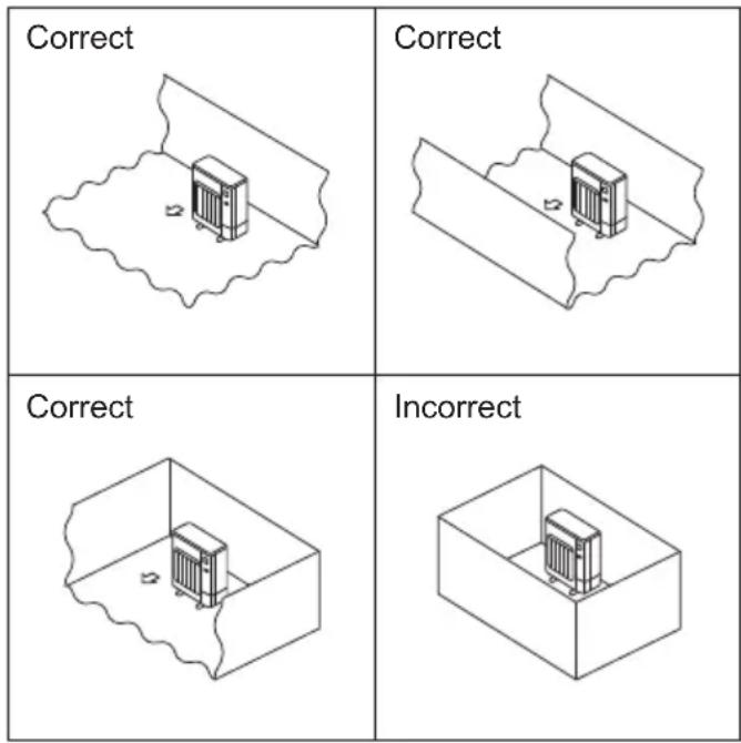
Fig. 2-2
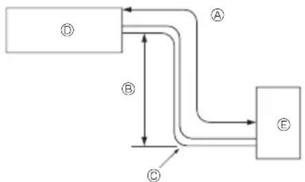
2.1. Refrigerant pipe (Fig. 2-1)
▶ Check that the difference between the heights of the indoor and outdoor units, the length of refrigerant pipe, and the number of bends in the pipe are within the limits shown below.
| Model | Pipe length (one way) | Height difference | Number of bends (one way) |
| S(H)WM60/80/100 | 2 m - 50 m Max. 30 m | Max. 10 | |
| S(H)WM120/140 2 | m - 30 m *1 Max. 30 m | Max. 10 |
*1 Only when the unit operates in heating, the pipe length available to use is 2 m - 50 m. Refer to section 4.
- Height difference limitation is defined regardless of which unit, indoor or outdoor, is positioned higher.
© Indoor unit
Outdoor unit
The insulation materials should be satisfied the following SPECs.
• Heat transfer rate: 0.040 W/mK or less
• Insulation thickness: 9 mm or more
• Heat resistance: 110°C or more
If the piping length in the outside is over 15 m, the insulation thickness should be 18 mm or more.
2.2. Choosing the outdoor unit installation location
R32 is heavier than air—as well as other refrigerants—so tends to accumulate at the base (in the vicinity of the floor). If R32 accumulates around base, it may reach a flammable concentration in case room is small. To avoid ignition, maintaining a safe work environment is required by ensuring appropriate ventilation. If a refrigerant leak is confirmed in a room or an area where there is insufficient ventilation, refrain from using of flames until the work environment can be improved by ensuring appropriate ventilation.
- Avoid locations exposed to direct sunlight or other sources of heat.
- Select a location from which noise emitted by the unit will not inconvenience neighbors.
- Select a location permitting easy wiring and pipe access to the power source and indoor unit.
- Avoid locations where combustible gases may leak, be produced, flow, or accumulate.
• Note that water may drain from the unit during operation.
- Select a level location that can bear the weight and vibration of the unit.
- Avoid locations where the unit can be covered by snow. In areas where heavy snow fall is anticipated, special precautions such as raising the installation location or installing a hood on the air intake must be taken to prevent the snow from blocking the air intake or blowing directly against it. This can reduce the airflow and a malfunction may result.
- Avoid locations exposed to oil, steam, or sulfuric gas.
- Use the transportation handles of the outdoor unit to transport the unit. If the unit is carried from the bottom, hands or fingers may be pinched.
• Refrigerant pipes connection shall be accessible for maintenance purposes.
Install outdoor units in a place where at least one of the four sides is open, and in a sufficiently large space without depressions. (Fig. 2-2)

CAUTION:
- Perform grounding.
Do not connect the ground wire to a gas pipe, water pipe arrester or telephone ground wire. Defective grounding could cause an electric shock.
- Do not install the unit in a place where an inflammable gas leaks.
If gas leaks and accumulates in the area surrounding the unit, it could cause an explosion.
• Install a ground leakage breaker depending on the installation place (where it is humid).
If a ground leakage breaker is not installed, it could cause an electric shock.
- Perform the drainage/piping work securely according to the installation manual.
If there is a defect in the drainage/piping work, water could drop from the unit and household goods could be wet and damaged.
- Fasten a flare nut with a torque wrench as specified in this manual.
When fastened too tight, a flare nut may be broken after a long period and cause a leakage of refrigerant.
(mm)
2.3. Outline dimensions (Outdoor unit) (Fig. 2-3)
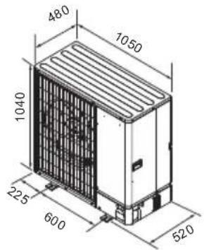
Fig. 2-3
natural_image
Simple line drawing of a rectangular box mounted on a base, with a small protrusion on top (no text or symbols)Fig. 2-4

natural_image
Isometric line drawing of a modular industrial or electrical enclosure with internal channels and a labeled section (A), no text or symbols present.Fig. 2-5
natural_image
Technical line drawing of a heat exchanger unit with airflow arrows and labeled component (B), no readable text or symbols present.Fig. 2-6
2.4. Ventilation and service space
2.4.1. Windy location installation
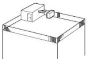
When installing the outdoor unit on a rooftop or other location unprotected from the wind, situate the air outlet of the unit so that it is not directly exposed to strong winds. Strong wind entering the air outlet may impede the normal airflow and a malfunction may result.
The following shows three examples of precautions against strong winds.
① Face the air outlet towards the nearest available wall about 35 cm away from the wall. (Fig. 2-4)
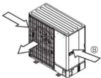
② Install an optional air guide if the unit is installed in a location where strong winds from a typhoon, etc. may directly enter the air outlet. (Fig. 2-5)
Air outlet guide
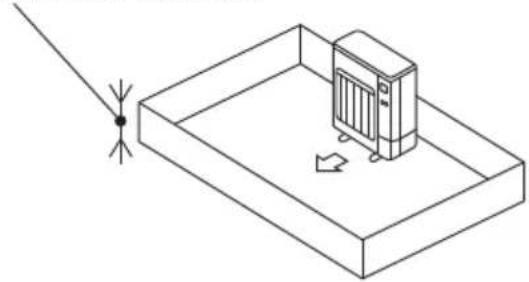
③ Position the unit so that the air outlet blows perpendicularly to the seasonal wind direction, if possible. (Fig. 2-6)
⑧ Wind direction
2.4.2. When installing a single outdoor unit (Refer to the last page)
Minimum dimensions are as follows, except for Max., meaning Maximum dimensions, indicated.
Refer to the figures for each case.
① Obstacles at rear only (Fig. 2-7)
② Obstacles at rear and above only (Fig. 2-8)
- Do not install the optional air outlet guides for upward airflow.
③ Obstacles at rear and sides only (Fig. 2-9)
④ Obstacles at front only (Fig. 2-10)
⑤ Obstacles at front and rear only (Fig. 2-11)
⑥ Obstacles at rear, sides, and above only (Fig. 2-12)
Do not install the optional air outlet guides for upward airflow.
2.4.3. When installing multiple outdoor units (Refer to the last page)
Leave 50 mm space or more between the units.
Refer to the figures for each case.
① Obstacles at rear only (Fig. 2-13)
② Obstacles at rear and above only (Fig. 2-14)
- No more than 3 units must be installed side by side. In addition, leave space as shown.
• Do not install the optional air outlet guides for upward airflow.
③ Obstacles at front only (Fig. 2-15)
④ Obstacles at front and rear only (Fig. 2-16)
⑤ Single parallel unit arrangement (Fig. 2-17)
When using an optional air outlet guide installed for upward airflow, the clearance is 500 mm or more.
⑥ Multiple parallel unit arrangement (Fig. 2-18)
* When using an optional air outlet guide installed for upward airflow, the clearance is 1000 mm or more.
⑦ Stacked unit arrangement (Fig. 2-19)
The units can be stacked up to two units high.
- No more than 2 stacked units must be installed side by side. In addition, leave space as shown.
2. Installation location
◎2.5. Minimum installation area
If you unavoidably install a unit in a space where all four sides are blocked or there are depressions, confirm that one of these situations (A, B or C) is satisfied.
Note: These countermeasures are for keeping safety not for specification guarantee.
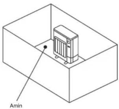
A) Secure sufficient installation space (minimum installation area Amin).
Install in a space with an installation area of Amin or more, corresponding to refrigerant quantity M (factory-charged refrigerant + locally added refrigerant).
| M [kg] Amin m^2 | |
| 1.0 12 | |
| 1.5 17 | |
| 2.0 23 | |
| 2.5 28 | |
| 3.0 34 | |
| 3.5 39 | |
| 4.0 45 | |
| 4.5 50 | |
| 5.0 56 | |
| 5.5 62 | |
| 6.0 67 | |
| 6.5 73 | |
| 7.0 78 | |
| 7.5 84 |
B) Install in a space with a depression height of ≤ 0.125 [m].
Height from the bottom of 0.125 [m] or less
natural_image
Isometric line drawing of a room with a server unit and a pointer, no text or symbols presentHeight from the bottom of 0.125 [m] or less
![cm of 0.125 [m] or less](/content/2026/04/733125/images/b5aeb51c8aa2a4a8f374f2f9a616fecc77fbb081e5325b5040d21df6b19f10e0.jpg)
C) Create an appropriate ventilation open area.
Make sure that the width of the open area is 0.9 [m] or more and the height of the open area is 0.15 [m] or more.
However, the height from the bottom of the installation space to the bottom edge of the open area should be 0.125 [m] or less.
Open area should be 75% or more opening.
![75% or more opening Width W 0.9 [m] or more Height H 0.15 [m] or more Height from the bottom 0.125 [m] or less](/content/2026/04/733125/images/9d17dda0b00b6c9d62b1ad11092948b88bb6c67c4b8f3700cdc6ad192bd4d6ce.jpg)
3. Installing the outdoor unit
en
natural_image
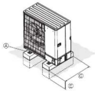
Isometric technical diagram of a mechanical or electrical component with labeled points A, B, C, E (no text or symbols beyond labels)
④ M10 (3/8") bolt
⑧ Base
© As long as possible.
① Vent
⑤ Set deep in the ground
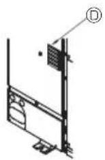
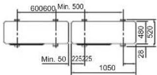
Fig. 3-1
(mm)
- Be sure to install the unit in a sturdy, level surface to prevent rattling noises during operation. (Fig. 3-1)
| Foundation bolt M10 (3/8") | |
| Thickness of concrete 120 mm | |
| Length of bolt 70 mm | |
| Weight-bearing capacity 320 kg |
- Make sure that the length of the foundation bolt is within 30 mm of the bottom surface of the base.
- Secure the base of the unit firmly with four-M10 foundation bolts in sturdy locations.
Installing the outdoor unit
- Do not block the vent. If the vent is blocked, operation will be hindered and break down may result.
- In addition to the unit base, use the installation holes on the back of the unit to attach wires, etc., if necessary to install the unit. Use self-tapping screws (ø5 × 15 mm or less) and install on site.

WARNING:
- The unit must be securely installed on a structure that can sustain its weight. If the unit is mounted on an unstable structure, it may fall down and cause damage or injuries.
- The unit must be installed according to the instructions in order to minimize the risk of damage from earthquakes, typhoons, or strong winds. An incorrectly installed unit may fall down and cause damage or injuries.

CAUTION:
• Install be unit on a rigid structure to prevent excessive operation sound or vibration.
4.1. Precautions for devices that use R32 refrigerant
- Refer to 1.5. for precautions not included below on using the outdoor unit with R32 refrigerant.
- Use ester oil, ether oil, alkylbenzene oil (small amount) as the refrigeration oil applied to the flared sections.
- Use C1220 copper phosphorus, for copper and copper alloy seamless pipes, to connect the refrigerant pipes. Use refrigerant pipes with the thicknesses specified in the table to the below. Make sure the insides of the pipes are clean and do not contain any harmful contaminants such as sulfuric compounds, oxidants, debris, or dust.
Always apply no-oxidation brazing when brazing the pipes, otherwise, the compressor will be damaged.
| Pipe size (mm) ø6 | .35 ø9.52 | ø12.7 ø | 15.88 | |
| Thickness (mm) | 0.8 | 0.8 | 0.8 | 1.0 |
| 19.05 | 22.2 | 25.4 | 28.58 |
| 1.0 | 1.0 | 1.0 | 1.0 |

WARNING:
When installing or relocating, or servicing the outdoor unit, use only the specified refrigerant (R32) to charge the refrigerant lines. Do not mix it with any other refrigerant and do not allow air to remain in the lines.
If air is mixed with the refrigerant, then it can be the cause of abnormal high pressure in the refrigerant line, and may result in an explosion and other hazards. The use of any refrigerant other than that specified for the system will cause mechanical failure or system malfunction or unit breakdown. In the worst case, this could lead to a serious impediment to securing product safety.
- Do not use pipes thinner than those specified above.
- Use a pipe compatible for the maximum allowable pressure for the outdoor unit.
Pipe wall thicker than the indications on the table is required for the pipes with larger diameter.
The maximum allowable pressure is indicated on the name plate.
- Use 1/2 H or H pipes if the diameter is 19.05 mm or larger.
☐ Be sure to have appropriate ventilation in order to prevent ignition. Furthermore, be sure to carry out fire prevention measures that there are no dangerous or flammable objects in the surrounding area.
4. Installing the refrigerant piping
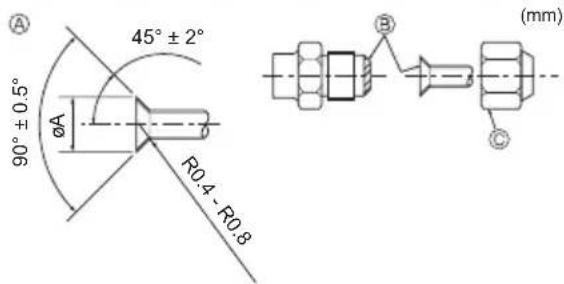
④ Flare cutting dimensions
① Flare nut tightening torque
Fig. 4-1
Ⓐ (Fig. 4-1)
| Copper pipe O.D. (mm) | Flare dimensionsøA dimensions (mm) |
| ø6.35 8.7 - 9.1 | |
| ø9.52 12.8 - 13.2 | |
| ø12.7 16.2 - 16.6 | |
| ø15.88 19.3 - 19.7 | |
| ø19.05 23.6 - 24.0 |
① (Fig. 4-1)
| Copper pipe O.D. (mm) | Flare nut O.D. (mm) | Tightening torque (N·m) |
| ø6.35 17 14 - 18 | ||
| ø6.35 22 34 - 42 | ||
| ø9.52 22 34 - 42 | ||
| ø12.7 26 49 - 61 | ||
| ø12.7 29 68 - 82 | ||
| ø15.88 29 68 - 82 | ||
| ø15.88 36 100 - 120 | ||
| ø19.05 36 100 - 120 |
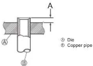
Fig. 4-2
4.2. Connecting pipes (Fig. 4-1)
- When commercially available copper pipes are used, wrap liquid and gas pipes with commercially available insulation materials (heat-resistant to 110°C or more, thickness of 12 mm or more). Direct contact with the bare piping may result in burns on frostbite.
- Apply thin layer of refrigerant oil to pipe and joint seating surface before tightening flare nut. Ⓐ
- Apply refrigerating machine oil over the entire flare seat surface. ⑥
- Use the flare nuts for the following pipe size. ©
- For connection, first align the center, then tighten the first 3 to 4 turns of flare nut by hand.
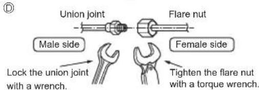
- Use 2 wrenches to tighten piping connections. ©
- Use leak detector or soapy water to check for gas leaks after connections are completed.
| SWM60 - 140, SHWM60 - 140 | ||
| Gas side | Pipe size (mm) | 12.7 or 15.88 |
| Liquid side | Pipe size (mm) | 6.35 |
- When bending the pipes, be careful not to break them. Bend radii of 100 mm to 150 mm are sufficient.
- Make sure the pipes do not contact the compressor and base plate for compressor. Abnormal noise or vibration may result.
①Pipes must be connected starting from the indoor unit.
Flare nuts must be tightened with a torque wrench.
② Flare the liquid pipes and gas pipes and apply a thin layer of refrigeration oil (Applied on site). - When usual pipe sealing is used, refer to Table 1 for flaring of R32 refrigerant pipes.
The size adjustment gauge can be used to confirm A measurements.
Table 1 (Fig. 4-2)
| Copper pipe O.D. (mm) | A (mm) |
| Flare tool for R32 | |
| Clutch type | |
| ø6.35 (1/4") 0 - 0.5 | |
| ø9.52 (3/8") 0 - 0.5 | |
| ø12.7 (1/2") 0 - 0.5 | |
| ø15.88 (5/8") | 0 - 0.5 |
| ø19.05 (3/4") | 0 - 0.5 |

WARNING:
When installing the unit, securely connect the refrigerant pipes before starting the compressor.
4. Installing the refrigerant piping
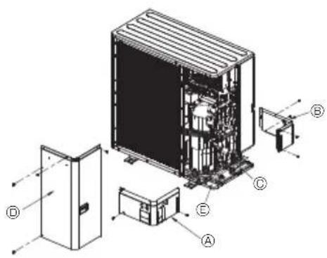
Fig. 4-3
④ Front piping cover
⑤ Rear piping cover
© Stop valve
① Service panel
⑤ Bend radius : 100 mm - 150 mm
4.3. Refrigerant piping (Fig. 4-3)
Remove the service panel Ⓐ (4 screws) and the front piping cover Ⓐ (2 screws) and rear piping cover Ⓐ (4 screws).
- Powders flaked from some rubber mounts will not cause any problems on the use of the outdoor unit.
- Do not let a refrigerant pipe make a contact with the baseplate.
Transmission of vibrations from the outdoor unit to indoor may cause sounds.
① Perform refrigerant piping connections for the indoor/outdoor unit when the outdoor unit's stop valve is completely closed.
② Vacuum-purge air from the indoor unit and the connection piping.
③ After connecting the refrigerant pipes, check the connected pipes and the indoor unit for gas leaks. (Refer to 4.4. Refrigerant pipe airtight testing method)
④ A high-performance vacuum pump is used at the stop valve service port to maintain a vacuum for an adequate time (at least one hour after reaching -101 kPa (5 Torr)) in order to vacuum dry the inside of the pipes. Always check the degree of vacuum at the gauge manifold. If there is any moisture left in the pipe, the degree of vacuum is sometimes not reached with short-time vacuum application.
After vacuum drying, completely open the stop valves (both liquid and gas) for the outdoor unit. This completely links the indoor and outdoor refrigerant circuits.
- If the vacuum drying is inadequate, air and water vapor remain in the refrigerant circuits and can cause abnormal rise of high pressure, abnormal drop of low pressure, deterioration of the refrigerating machine oil due to moisture, etc.
- If the stop valves are left closed and the unit is operated, the compressor and control valves will be damaged.
- Use a leak detector or soapy water to check for gas leaks at the pipe connection sections of the outdoor unit.
- Do not use the refrigerant from the unit to purge air from the refrigerant lines.
- After the valve work is completed, tighten the valve caps to the correct torque: 20 to 25 N·m (200 to 250 kgf·cm).
Failure to replace and tighten the caps may result in refrigerant leakage. In addition, do not damage the insides of the valve caps as they act as a seal to prevent refrigerant leakage.
⑤ Use sealant to seal the ends of the thermal insulation around the pipe connection sections to prevent water from entering the thermal insulation.
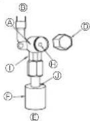
4. Installing the refrigerant piping
Stop valve
Stop valve
© Service port
① Open/Close section

© Local pipe
© Sealed, same way for gas side
⑬ Pipe cover
Fig. 4-4
(1)
(2)

Fig. 4-5 Fig. 4-6
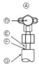
④ Valve body
⑤ Unit side
© Handle
① Cap
© Local pipe side
⑤ Pipe cover
Service port
⑧ Valve stem
① Double spanner section
(Do not apply a spanner other than to this section. Doing so would cause coolant leaks.)
Seal section
(Seal the end of the heat insulation material at the pipe connection section with whatever seal material you have on hand so that water does not infiltrate the heat insulation material.)
* The figure to the left is an example only.
The stop valve shape, service port position.
etc., may vary according to the model.
* Turn section ② only.
(Do not further tighten sections Ⓐ and Ⓑ together.)
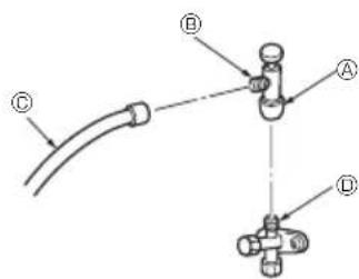
© Charge hose
© Service port
Fig. 4-7
4.4. Refrigerant pipe airtight testing method (Fig. 4-4)
(1) Connect the testing tools.
• Make sure the stop valves ^A ^B are closed and do not open them.
- Add pressure to the refrigerant lines through the service port (©) of the Gas stop valve (©).
(2) Do not add pressure to the specified pressure all at once; add pressure little by little.
① Pressurize to 0.5 MPa (5 kgf/cm ^2 G), wait five minutes, and make sure the pressure does not decrease.
② Pressurize to 1.5 MPa (15 kgf/cm ^-1 G), wait five minutes, and make sure the pressure does not decrease.
③ Pressurize to 4.15 MPa (41.5 kgf/cm ^3 G) and measure the surrounding temperature and refrigerant pressure.
(3) If the specified pressure holds for about one day and does not decrease, the pipes have passed the test and there are no leaks.
- If the surrounding temperature changes by 1 °C, the pressure will change by about 0.01 MPa (0.1 kgf/cm²G). Make the necessary corrections.
(4) If the pressure decreases in steps (2) or (3), there is a gas leak. Look for the source of the gas leak.
4.5. Stop valve opening method
The stop valve opening method varies according to the outdoor unit model. Use the appropriate method to open the stop valves.
(1) Liquid side (Fig. 4-5)
① Remove the cap and turn the valve rod counterclockwise as far as it will go with the use of a 4 mm hexagonal wrench. Stop turning when it hits the stopper. (Approximately 4 revolutions)
② Make sure that the stop valve is open completely, push in the handle and rotate the cap back to its original position.
(2) Gas side (Fig. 4-6)
① Remove the cap and turn the valve rod counterclockwise as far as it will go with the use of a 4 mm hexagonal wrench. Stop turning when it hits the stopper. (Approximately 9 revolutions)
② Make sure that the stop valve is open completely, push in the handle and rotate the cap back to its original position.
Refrigerant pipes are protectively wrapped
- The pipes can be protectively wrapped up to a diameter of 90 before or after connecting the pipes. Cut out the knockout in the pipe cover following the groove and wrap the pipes.
Pipe inlet gap - Use putty or sealant to seal the pipe inlet around the pipes so that no gaps remain. (If the gaps are not closed, noise may be emitted or water and dust will enter the unit and breakdown may result.)

CAUTION:
Precautions when using the charge valve (Fig. 4-7)
Do not tighten the service port too much when installing it, otherwise, the valve core could be deformed and become loose, causing a gas leak.
After positioning section Ⓑ in the desired direction, turn section Ⓐ only and tighten it.
Do not further tighten sections Ⓐ and Ⓑ together after tightening section Ⓐ.
4.6. Addition of refrigerant

WARNING:
- When the total refrigerant charge in the system exceeds 1.84 kg, comply with the minimum floor area requirements for the indoor unit. For more details, refer to the installation manual of the indoor unit.
- The chargeless piping length depends on the use so check the table below.
- If the piping length exceeds the chargeless piping length, charge R32 refrigerant additionally by following the procedure below.
* When the unit is stopped, charge the unit with the additional refrigerant through the gas stop valve after the pipe extensions and indoor unit have been vacuumized.
When the unit is operating, add refrigerant to the gas check valve using a safety charger. Do not add liquid refrigerant directly to the check valve.
* After charging the unit with refrigerant, note the added refrigerant amount on the service label (attached to the unit).
Refer to the "1.5. Using R32 refrigerant outdoor units" for more information.
* Calculate the additional refrigerant charging amount based on the formula in the table below. When the calculated total refrigerant amount (Initial amount + Additional charging amount) exceeds the maximum amount specified below, reduce the additional charging amount in order for the total amount to be the specified maximum amount.
R32 maintenance refilling: Before servicing refilling the equipment with R32 to ensure that there is no risk of explosion from electrical sparks it must be ensured that the equipment machine is 100% disconnected from the mains supply.
| Heating only | Initial amount | Chargeless piping length | Permitted piping length | Permitted vertical difference | Piping length | 2 to 3 m | -5 m | -10 m | -15 m | -20 m | -25 m | -30 m | -35 m | -40 m | -45 m | -50 m | Max. amount | ||
| PUZ- | S(H)WM60/80/100AA | 1.80 kg | 35 m | -50 m | -30 m | Total amount, kg | 1.30 *2 | 1.40 *2 | 1.50 *2 | 1.60 *2 | 1.70 *2 | 1.80 | 2.00 | 2.10 | 2.20 | 2.20 kg | |||
| Additional charge amount, kg | - | - | - | - | - | - | - | - | +0.20 | +0.30 | +0.40 | ||||||||
| S(H)WM120/140AA | 1.80 kg | 30 m | -50 m | -30 m | Total amount, kg | 1.50 *2 | 1.60 *2 | 1.70 *2 | 1.80 | 1.80 | 2.00 | 2.20 | 2.30 | 2.40 | 2.40 kg | ||||
| Additional charge amount, kg | - | - | - | - | - | - | - | +0.20 | +0.40 | +0.50 | +0.60 | ||||||||
| Reversible(Cooling and Heating) | Initial amount | Chargeless piping length | Permitted piping length | Permitted vertical difference | Piping length | 2 to 3 m | -5 m | -10 m | -15 m | -20 m | -25 m | -30 m | -35 m | -40 m | -45 m | -50 m | Max. amount | ||
| PUZ- | S(H)WM60/80/100AA | 1.80 kg | 15 m | -50 m | -30 m | Total amount, kg | 1.70 *2 | 1.80 | 1.80 | 1.90 | 2.00 | 2.10 | 2.20 | 2.30 | 2.40 | 2.40 kg | |||
| Additional charge amount, kg | - | - | - | - | +0.10 | +0.20 | +0.30 | +0.40 | +0.50 | +0.60 | |||||||||
| S(H)WM120/140AA | 1.80 kg | None. *1 | -30 m | -30 m | Total amount, kg | 2.20 | 2.30 | 2.40 | 2.40 kg | ||||||||||
| Additional charge amount, kg | +0.40 | +0.50 | +0.60 | ||||||||||||||||
*1 The piping length of 5 m is usable if the cases below are allowable.
• The maximum cooling capacity may drop over 20 percent. In this case, cooling efficiency will be less and the input increases as well.
- The running-water noise may occur from the extended pipings or the indoor unit.
*2 These values are recommended only in the case of recharging. At the initial installment, an adjustment for the amounts of refrigerant is not necessary.
*3 When setting the water temperature to 60^ or higher, add the refrigerant amount for the "reversible" even when using the "heating only". Otherwise, the system may not operate due to the refrigerant shortage.
5. Drainage piping work
Outdoor unit drainage pipe connection (PUZ-SWM)
When drain piping is necessary, use the drain socket or the drain pan (option).
Note:
Do not use the drain socket and drain pan in the cold region.
Drain may freeze and it makes the fan stop.
| Drain socket PAC-SG6 | DS-E |
| Drain pan PAC-SJ83DP | -E |
en
6. Water piping work
6.1. Minimum water quantity
Refer to the indoor unit installation manual.
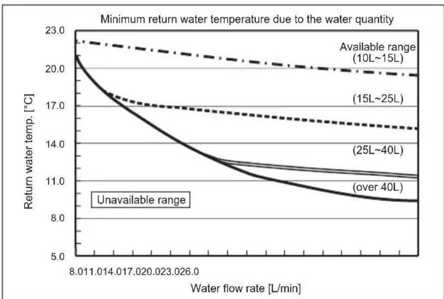
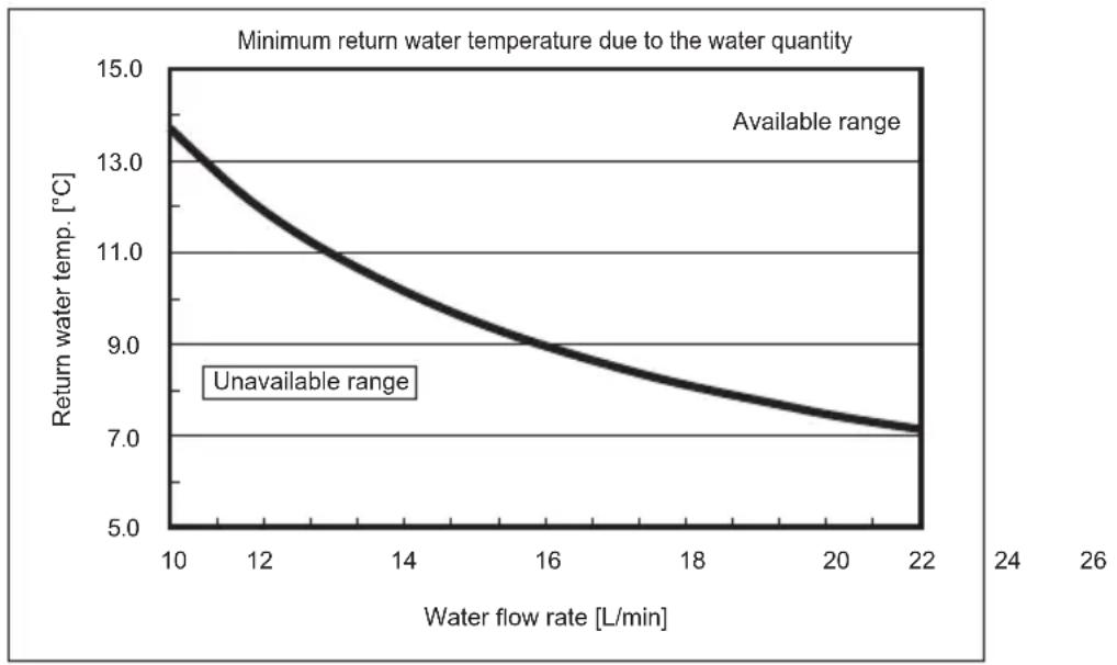
6.2. Available range (Water flow rate, return water temp.)
Ensure the following water flow rate and return temperature range in the water circuit.
These curves are related to the water quantity.
■ Heating
PUZ-SWM60, 80, 100
PUZ-SHWM60, 80, 100
line
| Water flow rate [L/min] | Available range (10L~15L) | (15L~25L) | (25L~40L) | (over 40L) | | ----------------------- | -------------------------- | --------- | --------- | ---------- | | 8.011 | 22.5 | 20.0 | 17.0 | 13.0 | | 1.014 | 22.0 | 19.5 | 16.5 | 12.5 | | 1.017 | 21.5 | 19.0 | 16.0 | 12.0 | | 2.020 | 21.0 | 18.5 | 15.5 | 11.5 | | 2.023 | 20.5 | 18.0 | 15.0 | 11.0 | | 2.026 | 20.0 | 17.5 | 14.5 | 10.5 | | 8.011 | Unavailable | Unavailable| Unavailable| Unavailable| | 1.014 | Unavailable | Unavailable| Unavailable| Unavailable| | 1.017 | Unavailable | Unavailable| Unavailable| Unavailable| | 2.020 | Unavailable | Unavailable| Unavailable| Unavailable| | 2.023 | Unavailable | Unavailable| Unavailable| Unavailable| | 2.026 | Unavailable | Unavailable| Unavailable| Unavailable| | 8.011 | Unavailable | Unavailable| Unavailable| Unavailable| | 1.014 | Unavailable | Unavailable| Unavailable| Unavailable| | 1.017 | Unavailable | Unavailable| Unavailable| Unavailable| | 2.020 | Unavailable | Unavailable| Unavailable| Unavailable| | 2.023 | Unavailable-------------------- | Unavailable| Unavailable| Unavailable| | 2.026 | Unavailable | Unavailable| Unavailable| Unavailable| | 8.011 | Unavailable | Unavailable| Unavailable| Unavailable| | 1.014 | Unavailable | Unavailable| Unavailable| Unavailable| | 1.017 | Unavailable | Unavailable| Unavailable| Unavailable| | ... | ... | ... | ... | ... | | 8.011 | ... | ... | ... | ... | | 1.014 | ... | ... | ... | ... | | 1.017 | ... | ... | ... | ... | | 2.020 | ... | ... | ... | ... | | 2.023 | ... | ... | ... | ... | | 2.026 | ... | ... | ... | ... | | ... | ... | ... | ... | ... | | 8.011 | ... | ... | ... | ... | | 1.014 | ... | ... | ... | ... | | 1.017 | ... | ... | ... | ... | | 2.020 | ... | ... | ... | ... |PUZ-SWM120, 140
PUZ-SHWM120, 140
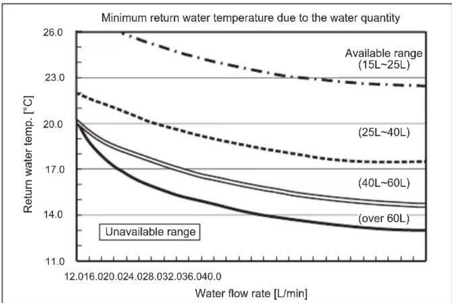
line
| Water flow rate [L/min] | Available range (15L~25L) | (25L~40L) | (40L~60L) | (over 60L) | | ----------------------- | -------------------------- | --------- | --------- | ---------- | | 12.016 | 26.0 | 20.0 | 17.0 | 14.0 | | 12.020 | 25.5 | 19.5 | 16.5 | 13.8 | | 12.024 | 25.0 | 19.0 | 16.0 | 13.6 | | 12.028 | 24.5 | 18.5 | 15.5 | 13.4 | | 12.032 | 24.0 | 18.0 | 15.0 | 13.2 | | 12.036 | 23.5 | 17.5 | 14.5 | 13.0 | | 12.040 | 23.0 | 17.0 | 14.0 | 12.8 | | 12.044 | 22.5 | 16.5 | 13.5 | 12.6 | | 12.048 | 22.0 | 16.0 | 13.0 | 12.4 | | 12.052 | 21.5 | 15.5 | 12.5 | 12.2 | | 12.056 | 21.0 | 15.0 | 12.0 | 12.0 | | 12.060 | 20.5 | 14.5 | 11.5 | 11.8 | | 12.064 | 20.0 | 14.0 | 11.0 | 11.6 | | 12.068 | 19.5 | 13.5 | 10.5 | 11.4 | | 12.072 | 19.0 | 13.0 | 10.0 | 11.2 | | 12.076 | 18.5 | 12.5 | 9.5 | 11.0 | | 12.080 | 18.0 | 12.0 | 9.0 | 10.8 | | 12.084 | 17.5 | 11.5 | 8.5 | 10.6 | | 12.088 | 17.0 | 11.0 | 8.0 | 10.4 | | 12.092 | 16.5 | 10.5 | 7.5 | 10.2 | | 12.096 | 16.0 | 10.0 | 7.0 | 10.0 | | 12.100 | 15.5 | 9.5 | 6.5 | 9.8 | | 12.104 | 15.0 | 9.0 | 6.0 | 9.6 | | 12.108 | 14.5 | 8.5 | 5.5 | 9.4 | | 12.112 | 14.0 | 8.0 | 5.0 | 9.2 | | 12.116 | 13.5 | 7.5 | 4.5 | 9.0 | | 12.120 | 13.0 | 7.0 | 4.0 | 8.8 | | 12.124 | 12.5 | 6.5 | 3.5 | 8.6 | | 12.128 | 12.0 | 6.0 | 3.0 | 8.4 | | 12.132 | 11.5 | 5.5 | 2.5 | 8.2 | | 12.136 | 11.0 | 5.0 | 2.0 | 8.0 | | 12.140 | 10.5 | 4.5 | 1.5 | 7.8 | | 12.144 | 10.0 | 4.0 | 1.0 | 7.6 | | 12.148 | 9.5 | 3.5 | - | - | | 12.152 | 9.0 | 3.0 | - | - | | 12.156 | 8.5 | 2.5 | - | - | | 12.160 | 8.0 | 2.0 | - | - | | 12.164 | 7.5 | - | - | - | | 12.168 | - | - | - | - | | 12.172 | - | - | - | - | | 12.176 | - | - | - | - | | 12.180 | - | - | - | - | | 12.184 | - | - | - | - | | 12.188 | - | - | - | - | | 12.192 | - | - | - | - | | 12.196 | - | - | - | - | | 12.200 | - | - | - | - | | 12.204 | - | - | - | - | | 12.208 | - | - | - | - | | 12.212 | - | - | - | - | | 12.216 | - | - | - | - | | 12.220 | - | - | - | - | | 12.224 | - | - | - | - | | 12.228 | - | - | - | - | | 12.232 | - | - | - | - | | 12.236 | - | - | - | - | | 12.240 | - | - | - | - | | 12.244 | - | - | - | - | | 12.248 | - | - | - | - | | 12.252 | - | - | - | - | | 12.256 | - | - | - | - | | 12.260 | - | - | - | - | | 12.264 | - | - | - | - | | 12.268 | - | - | - | - | | 12.272 | - | - | - | - | | 12.276 | - | - | - | - | | 12.280 | - | - | - | - | | 12.284 | - | - | - | - | | 12.288 | - | - | - | - | | 12.292 | - | - | - | - | | 12.296 | - | - | - | - | | 12.300 | - | - | - | - | | 12.304 | - | - | - | - | | Note: The data is already in the required format for minimum return water temperature due to the water quantity and available range (in L/min). This is not included in the original data series in the code provided in the code itself.Note:
Be sure to avoid the unavailable range during defrosting.
Otherwise, the outdoor unit is insufficiently defrosted and/or the heat exchanger of the indoor unit may freeze.
Cooling
PUZ-SWM60, 80, 100
PUZ-SHWM60, 80, 100
line
| Water flow rate [L/min] | Return water temp. [°C] | | ----------------------- | ------------------------ | | 10 | 13.5 | | 12 | 12.0 | | 14 | 10.5 | | 16 | 9.0 | | 18 | 8.0 | | 20 | 7.5 | | 22 | 7.0 |PUZ-SWM120, 140
PUZ-SHWM120, 140
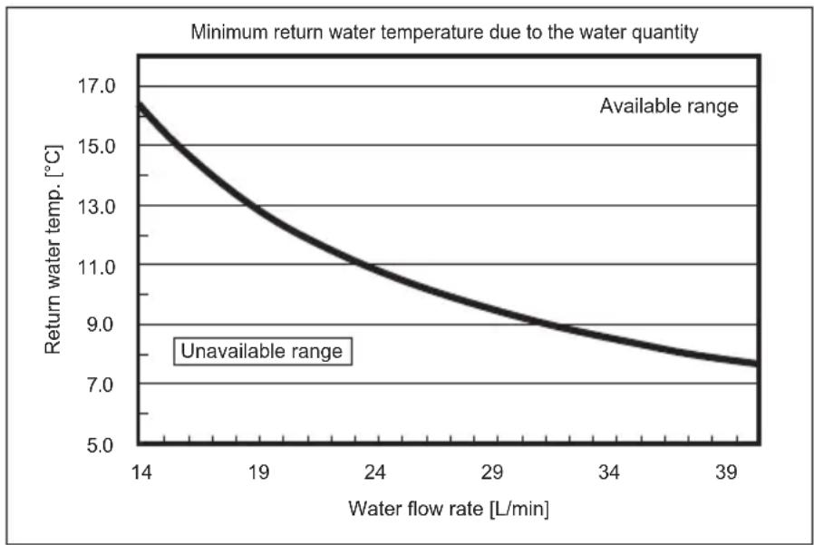
line
| Water flow rate [L/min] | Return water temp. [°C] | | ----------------------- | ------------------------ | | 14 | 17.0 | | 19 | 13.0 | | 24 | 11.0 | | 29 | 9.0 | | 34 | 8.0 | | 39 | 7.0 |Note:
Be sure to avoid the unavailable range during defrosting.
Otherwise, the outdoor unit is insufficiently defrosted and/or the heat exchanger of the indoor unit may freeze.
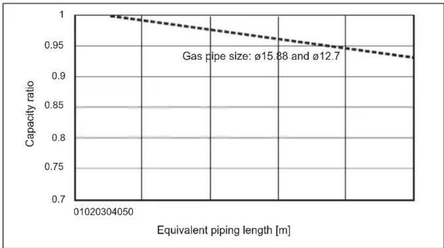
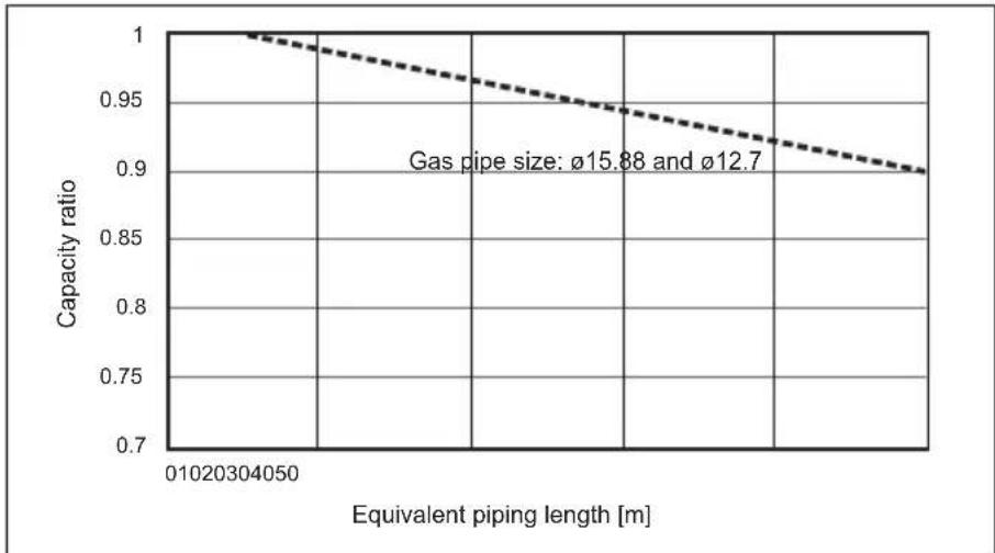
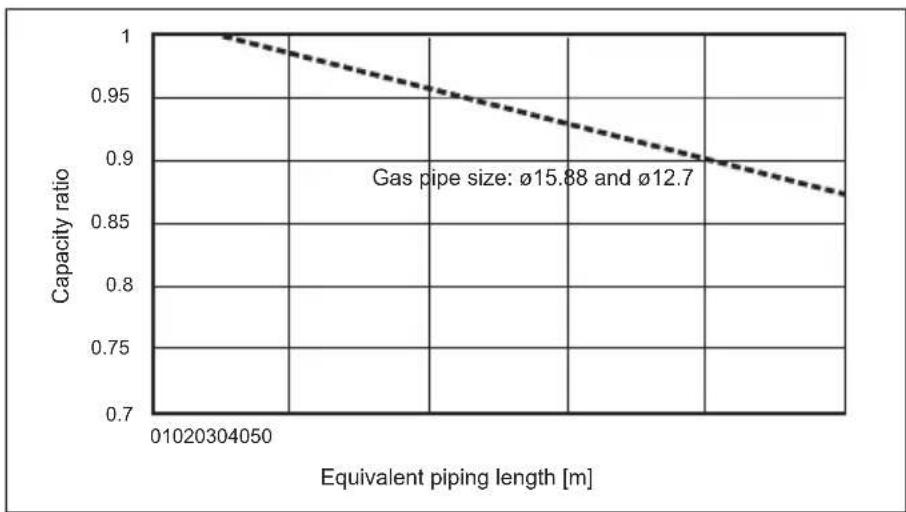
6.3 Correcting capacity for changes in the length and diameter of refrigerant pipe
The capacity depends on the length and diameter of refrigerant piping.
Check the length and diameter to operate the air conditioner in an adequate capacity.
■ Heating
PUZ-SWM60, 80, 100
PUZ-SHWM60, 80, 100
en
line
| Equivalent piping length [m] | Capacity ratio | | ---------------------------- | -------------- | | 01020304050 | 1.00 | | 01020304050 | 0.98 | | 01020304050 | 0.96 | | 01020304050 | 0.94 | | 01020304050 | 0.92 | | 01020304050 | 0.90 | | 01020304050 | 0.88 | | 01020304050 | 0.86 | | 01020304050 | 0.84 | | 01020304050 | 0.82 | | 01020304050 | 0.80 | | 01020304050 | 0.78 | | 01020304050 | 0.76 | | 01020304050 | 0.74 | | 01020304050 | 0.72 | | 01020304050 | 0.70 |PUZ-SWM120
PUZ-SHWM120
line
| Equivalent piping length [m] | Capacity ratio | | ---------------------------- | -------------- | | 01020304050 | 1.00 | | 01020304050 | 0.98 | | 01020304050 | 0.96 | | 01020304050 | 0.94 | | 01020304050 | 0.92 | | 01020304050 | 0.90 |PUZ-SWM140
PUZ-SHWM140
line
| Equivalent piping length [m] | Capacity ratio | | ---------------------------- | -------------- | | 01020304050 | 1.00 | | | 0.95 | | | 0.90 | | | 0.85 |6. Water piping work
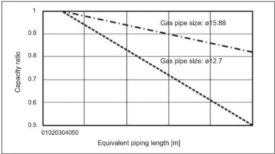
Cooling
PUZ-SWM60, 80, 100
PUZ-SHWM60, 80, 100
line
| Equivalent piping length [m] | Gas pipe size: ø15.88 | Gas pipe size: ø12.7 | | ---------------------------- | --------------------- | -------------------- | | 01020304050 | 1.0 | 1.0 | | (additional points) | 0.9 | 0.8 | | (additional points) | 0.8 | 0.6 | | (additional points) | 0.7 | 0.5 |PUZ-SWM120
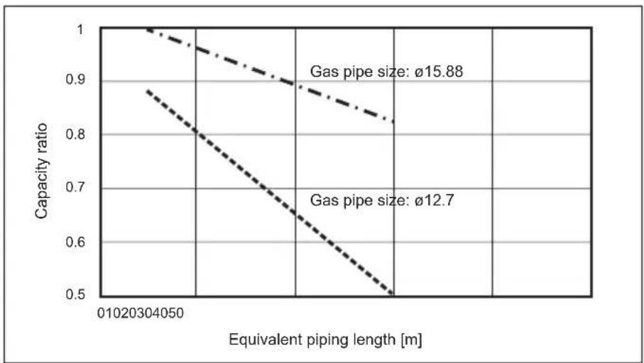
PUZ-SHWM120
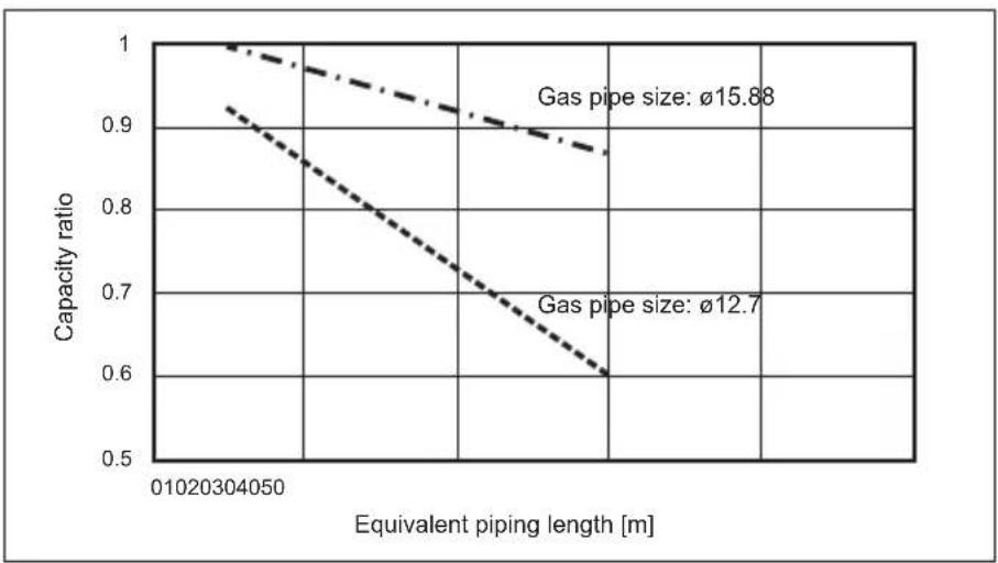
PUZ-SWM140
PUZ-SHWM140
line
| Equivalent piping length [m] | Gas pipe size: Ø15.88 | Gas pipe size: Ø12.7 | | ---------------------------- | --------------------- | -------------------- | | 01020304050 | 1.0 | 0.88 | | 01020304050 | 0.95 | 0.80 | | 01020304050 | 0.90 | 0.70 | | 01020304050 | 0.85 | 0.60 | | 01020304050 | 0.80 | 0.50 |7. Electrical work
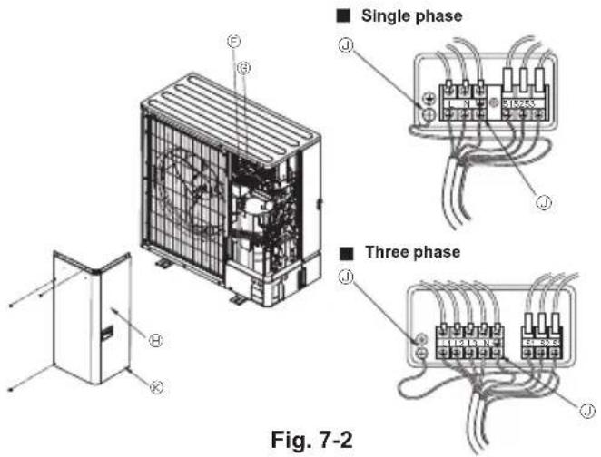
7.1. Outdoor unit (Fig. 7-1, Fig. 7-2)
① Remove the service panel.
② Wire the cables referring to the Fig. 7-1 and the Fig. 7-2.
flowchart
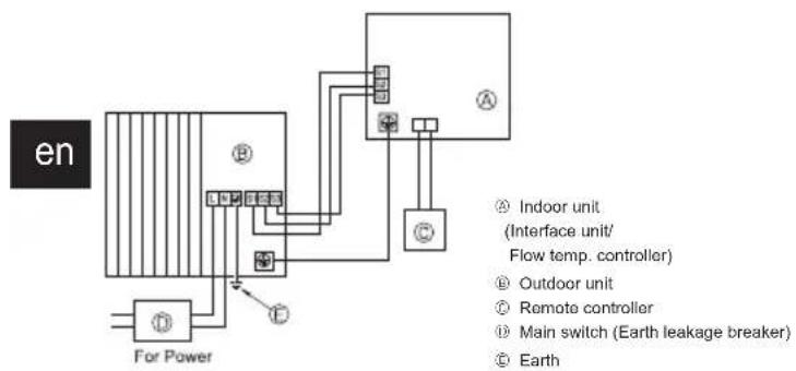
graph TD
    A["For Power"] --> B["Indoor unit (Interface unit/Flow temp. controller)"]
    B --> C["Outdoor unit"]
    C --> D["Remote controller"]
    D --> E["Main switch (Earth leakage breaker)"]
    E --> F["Earth"]
Fig. 7-1
Terminal block
Indoor/Outdoor connection terminal block (S1, S2, S3)
⑧ Service panel
① Earth terminal
① Wire the cables so that they do not contact the center of the service panel.
Note:
If the protective sheet for the electrical box is removed during servicing, be sure to reinstall it.

CAUTION:
Be sure to install N-Line. Without N-Line, it could cause damage to unit.
7.2. Field electrical wiring
| Outdoor unit model | SWM60VSHWM60V | SWM80V | SHWM80VSWM100V | SHWM100V | SWM120/140VSHWM120V | ||
| Outdoor unit power supply | ~/N (single),50 Hz, 230 V | ~/N (single),50 Hz, 230 V | ~/N (single),50 Hz, 230 V | ~/N (single),50 Hz, 230 V | ~/N (single),50 Hz, 230 V | ||
| Outdoor unit input capacity Main switch (Breaker) *1 16 A 20 A 25 A 30 | A 32 A | ||||||
| Wiring WireNo. × size(mm2) | Outdoor unit power supply 3 × Min. 2.5 3 × Min. 2.5 3 × Min. | 2.5 3 × Min. 4 3 × Min. 4 | |||||
| Indoor unit-Outdoor unit | *2 | 3 × 1.5 (Polar) | 3 × 1.5 (Polar) | 3 × 1.5 (Polar) | 3 × 1.5 (Polar) | 3 × 1.5 (Polar) | |
| Indoor unit-Outdoor unit earth *2 1 × Min. 1.5 1 × Min. 1.5 1 | × Min. 1.5 1 × Min. 1.5 1 | × Min. 1.5 | |||||
| Remote controller-Indoor unit | *3 | 2 × 0.3 (Non-polar) | 2 × 0.3 (Non-polar) | 2 × 0.3 (Non-polar) | 2 × 0.3 (Non-polar) | 2 × 0.3 (Non-polar) | |
| Circuit rating | Outdoor unit L-N (single)Outdoor unit L1-N, L2-N, L3-N (3 phase) | *4 | 230 VAC | 230 VAC | 230 VAC | 230 VAC | 230 VAC |
| Indoor unit-Outdoor unit S1-S2 | *4 | 230 VAC | 230 VAC | 230 VAC | 230 VAC | 230 VAC | |
| Indoor unit-Outdoor unit S2-S3 | *4 | 28 VDC | 28 VDC | 28 VDC | 28 VDC | 28 VDC | |
| Remote controller-Indoor unit | *4 | 12 VDC | 12 VDC | 12 VDC | 12 VDC | 12 VDC | |
| Outdoor unit model | SHWM140V | SWM80 - 140YSHWM80 - 140Y | ||
| Outdoor unit power supply | -/N (single),50 Hz, 230 V | 3N- (3 ph 4-wires),50 Hz, 400 V | ||
| Outdoor unit input capacity Main switch (Breaker) *1 40 A 16 A | ||||
| Wiring WireNo. × size(mm2) | Outdoor unit power supply | 3 × Min. 6 5 × Min. | 1.5 | |
| Indoor unit-Outdoor unit *2 3 × 1.5 (Polar) 3 × 1.5 (Polar) | ||||
| Indoor unit-Outdoor unit earth *2 1 × Min. 1.5 1 × Min. 1.5 | ||||
| Remote controller-Indoor unit *3 2 × 0.3 (Non-polar) 2 × 0.3 | (Non-polar) | |||
| Circuit rating | Outdoor unit L-N (single)Outdoor unit L1-N, L2-N, L3-N (3 phase) | *4 | 230 VAC | 230 VAC |
| Indoor unit-Outdoor unit S1-S2 | *4 | 230 VAC | 230 VAC | |
| Indoor unit-Outdoor unit S2-S3 | *4 | 28 VDC | 28 VDC | |
| Remote controller-Indoor unit *4 | 12 VDC | 12 VDC | ||
*1. A breaker with at least 3.0 mm contact separation in each poles shall be provided. Use earth leakage breaker (NV).
Make sure that the current leakage breaker is one compatible with higher harmonics.
Always use a current leakage breaker that is compatible with higher harmonics as this unit is equipped with an inverter.
The use of an inadequate breaker can cause the incorrect operation of inverter.
*2. Max. 45 m
If 2.5 mm² used, Max. 50 m
If 2.5 mm ^2 used and S3 separated, Max. 80 m
*3. The 10 m wire is attached in the remote controller accessory.
*4. The figures are NOT always against the ground.
S3 terminal has 28 VDC against S2 terminal. However between S3 and S1, these terminals are NOT electrically insulated by the transformer or other device.
Notes: 1. Wiring size must comply with the applicable local and national codes.
2. Power supply cables and the cables between Interface unit/Flow temp. controller and outdoor unit shall not be lighter than polychloroprene sheathed flexible cables. (Design 60245 IEC 57)
3. Be sure to connect the cables between Interface unit/Flow temp. controller and outdoor unit directly to the units (no intermediate connections are allowed). Intermediate connections may result in communication errors. If water enters at the intermediate connection point, it may cause insufficient insulation to ground or a poor electrical contact.
(If an intermediate connection is necessary, be sure to take measures to prevent water from entering the cables.)
4. Install an earth longer than other cables.
5. Do not construct a system with a power supply that is turned ON and OFF frequently.
6. Use self-extinguishing distribution cables for power supply wiring.
7. Properly route wiring so as not to contact the sheet metal edge or a screw tip.
flowchart
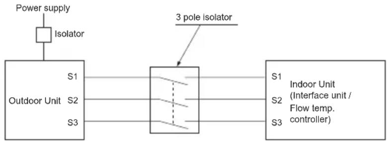
graph LR
    A["Power supply"] --> B["Isolator"]
    B --> C["Outdoor Unit S1"]
    B --> D["Outdoor Unit S2"]
    B --> E["Outdoor Unit S3"]
    C --> F["3 pole isolator"]
    D --> F
    E --> F
    F --> G["S1 Indoor Unit (Interface unit / Flow temp. controller)"]

WARNING:
- In case of A-control wiring, there is high voltage potential on the S3 terminal caused by electrical circuit design that has no electrical insulation between power line and communication signal line. Therefore, please turn off the main power supply when servicing. And do not touch the S1, S2, S3 terminals when the power is energized. If isolator should be used between indoor unit and outdoor unit, please use 3 pole type.
Never splice the power cable or the indoor-outdoor connection cable, otherwise it may result in a smoke, a fire or communication failure.
8. Test run
8.1. Before test run
▶ After completing installation and the wiring and piping of the indoor and outdoor units, check for refrigerant leakage, looseness in the power supply or control wiring, wrong polarity, and no disconnection of one phase in the supply.
▶ Use a 500-volt megohmmeter to check that the resistance between the power supply terminals and ground is at least 1 MΩ.
▶ Do not carry out this test on the control wiring (low voltage circuit) terminals.
en

WARNING:
Do not use the outdoor unit if the insulation resistance is less than 1 MΩ.
Insulation resistance
After installation or after the power source to the unit has been cut for an extended period, the insulation resistance will drop below 1 MΩ due to refrigerant accumulating in the compressor. This is not a malfunction. Perform the following procedures.
- Remove the wires from the compressor and measure the insulation resistance of the compressor.
- If the insulation resistance is below 1 MΩ, the compressor is faulty or the resistance dropped due the accumulation of refrigerant in the compressor.
- After connecting the wires to the compressor, the compressor will start to warm up after power is supplied. After supplying power for the times indicated below, measure the insulation resistance again.
- The insulation resistance drops due to accumulation of refrigerant in the compressor. The resistance will rise above 1 MΩ after the compressor is warmed up for 4 hours.
(The time necessary to warm up the compressor varies according to atmospheric conditions and refrigerant accumulation.)
- To operate the compressor with refrigerant accumulated in the compressor, the compressor must be warmed up at least 12 hours to prevent breakdown.
- If the insulation resistance rises above 1 MΩ, the compressor is not faulty.

CAUTION:
- The compressor will not operate unless the power supply phase connection is correct.
-
Turn on the power at least 12 hours before starting operation.
-
Starting operation immediately after turning on the main power switch can result in severe damage to internal parts. Keep the power switch turned on during the operational season.
- The outdoor unit might NOT run, in order to protect the compressor, when the following two conditions holds.
- The outdoor unit was not supplied power for a while.
- It is below freezing temperature.
It may last up to 12 hours until the unit runs.
▶ The followings must be checked as well.
- The outdoor unit is not faulty. LED1 and LED2 on the control board of the outdoor unit flash when the outdoor unit is faulty.
• Both the gas and liquid stop valves are completely open. - A protective sheet covers the surface of the DIP switch panel on the control board of the outdoor unit. Remove the protective sheet to operate the DIP switches easily.
8.2. Test run
8.2.1. Using remote controller
Refer to the indoor unit installation manual.
Note :
Occasionally, vapor that is made by the defrost operation may seem as if smoke come up from the outdoor unit.
9. Special Functions
flowchart
graph TD
    A["SW1"] --> B["X"]
    B --> C["Orange"]
    B --> D["Brown"]
    B --> E["Red"]
    C --> F["CNDM"]
    D --> F
    E --> F
    style A fill:#f9f,stroke:#333
    style B fill:#ccf,stroke:#333
    style C fill:#cfc,stroke:#333
    style D fill:#fcc,stroke:#333
    style E fill:#cff,stroke:#333
    style F fill:#ffc,stroke:#333
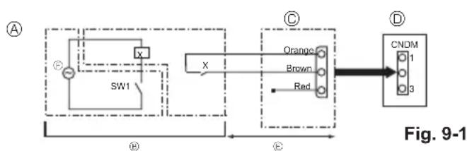
Ⓐ Circuit diagram example
(low noise mode)
⑥ On-site arrangement
© External input adapter (PAC-SC36NA-E)
X: Relay
© Outdoor unit control board
© Max. 10 m
© Power supply for relay
9.1. Low noise mode (on-site modification) (Fig. 9-1)
9.1.1. Using the CNDM connector (Option)
By performing the following modification, operation noise of the outdoor unit can be reduced.
The low noise mode will be activated when a commercially available timer or the contact input of an ON/OFF switch is added to the CNDM connector (option) on the control board of the outdoor unit.
• The ability varies according to the outdoor temperature and conditions, etc.
① Complete the circuit as shown when using the external input adapter (PAC-SC36NA-E). (Option)
② SW7-1 (Outdoor unit control board): OFF
③ SW1 ON: Low noise mode
SW1 OFF: Normal operation
9.1.2. Using remote controller
Refer to the indoor unit installation manual.
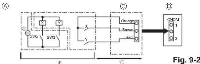
9.2. Demand function (on-site modification) (Fig. 9-2)
By performing the following modification, energy consumption can be reduced to 0–100% of the normal consumption.
The demand function will be activated when a commercially available timer or the contact input of an ON/OFF switch is added to the CNDM connector (option) on the control board of the outdoor unit.
① Complete the circuit as shown when using the external input adapter (PAC-SC36NA-E). (Option)
② By setting SW7-1 on the control board of the outdoor unit, the energy consumption (compared to the normal consumption) can be limited as shown below.
| SW7-1 SW2 SW3 Energy consumption | ||||
| Demand function | ON | OFF | OFF | 100% |
| ON | OFF | 75% | ||
| ON | ON | 50% | ||
| OFF | ON | 0% (Stop) | ||
flowchart
graph TD
    A["Switch SW2"] --> B["Switch SW3"]
    B --> C["Orange"]
    B --> D["Brown"]
    B --> E["Red"]
    C --> F["CNDM"]
    D --> F
    E --> F
    style A fill:#f9f,stroke:#333
    style B fill:#ccf,stroke:#333
    style C fill:#cfc,stroke:#333
    style D fill:#fcc,stroke:#333
    style E fill:#cff,stroke:#333
    style F fill:#ffc,stroke:#333
Ⓐ Circuit diagram example (Demand function)
⑧ On-site arrangement
X, Y: Relay
◎ External input adapter (PAC-SC36NA-E)
Outdoor unit control board
© Max. 10 m
⑤ Power supply for relay
9.3. Refrigerant collecting (pump down)
Perform the following procedures to collect the refrigerant when moving the indoor unit or the outdoor unit.
① Supply power (circuit breaker).
* When power is supplied, make sure that "CENTRALLY CONTROLLED" is not displayed on the remote controller. If "CENTRALLY CONTROLLED" is displayed, the refrigerant collecting (pump down) cannot be completed normally.
* Start-up of the indoor-outdoor communication takes about 3 minutes after the power (circuit breaker) is turned on. Start the pump-down operation 3 to 4 minutes after the power (circuit breaker) is turned ON.
* In the case of multi-units control, before powering on, disconnect the wiring between the master indoor unit and the slave indoor unit. For more details refer to the installation manual for the indoor unit.
② After the liquid stop valve is closed, set the SWP switch on the control board of the outdoor unit to ON. The compressor (outdoor unit) and ventilators (indoor and outdoor units) start operating and refrigerant collecting operation begins. LED1 and LED2 on the control board of the outdoor unit are lit.
* Only set the SWP switch (push-button type) to ON if the unit is stopped. However, even if the unit is stopped and the SWP switch is set to ON less than 3 minutes after the compressor stops, the refrigerant collecting operation cannot be performed. Wait until compressor has been stopped for 3 minutes and then set the SWP switch to ON again.
③ Because the unit automatically stops in about 2 to 3 minutes when the refrigerant collecting operation is completed (LED1 off, LED2 lit), be sure to quickly close the gas stop valve. If LED1 is lit and LED2 is off and the outdoor unit is stopped, refrigerant collection is not properly performed. Open the liquid stop valve completely, and then repeat step ② after 3 minutes have passed.
* If the refrigerant collecting operation has been completed normally (LED1 off, LED2 lit), the unit will remain stopped until the power supply is turned off.
④ Turn off the power supply (circuit breaker).
* Note that when the extension piping is very long with large refrigerant amount, it may not be possible to perform a pump-down operation. When performing the pump-down operation, make sure that the low pressure is lowered to near 0 MPa (gauge).
WARNING:
- When pumping down the refrigerant, stop the compressor before disconnecting the refrigerant pipes. The compressor may burst if air etc. get into it.
- Do not perform pump down work when there is a gas leak. The intake of air or other gases causes abnormally high pressure in the refrigeration cycle, which may cause explosion or injury.
10. System control
Set the refrigerant address using the DIP switch of the outdoor unit.
SW1 Function Setting
| SW1 Setting | Refrigerant address |
| ONOFF3 4 5 6 7 | 00 |
| ONOFF3 4 5 6 7 | 01 |
| ONOFF3 4 5 6 7 | 02 |
| SW1 Setting | Refrigerant address |
| ONOFF3 4 5 6 7 | 03 |
| ONOFF3 4 5 6 7 | 04 |
| ONOFF3 4 5 6 7 | 05 |
Note:
a) Up to 6 units can be connected.
b) Select one single model for all units.
c) For Dip switch setting for indoor unit, refer to the indoor unit's installation manual.
11. Specifications
| Outdoor model | PUZ-SWM60VAA | PUZ-SWM80VAA | PUZ-SWM100VAA | PUZ-SWM120VAA | PUZ-SWM140VAA | |
| Power supply V / Phase / | Hz 230 / Single / | 50 | ||||
| Dimensions (W × H × D) mm | 1050 × 1040 | × 480 | ||||
| Sound Power Level *1 (Heating) | dB(A) | 54 58 | ||||
| Outdoor model | PUZ-SHWM60VAA | PUZ-SHWM80VAA P | UZ-SHWM100VAA P | UZ-SHWM120VAA P | UZ-SHWM140VAA | |
| Power supply V / Phase / Hz 230 / Single / mm 1050 × 1040 | 50 | |||||
| Dimensions (W × H × D) | × 480 | |||||
| Sound Power Level *1 (Heating) | dB(A) | 54 58 | ||||
| Outdoor model | PUZ-SWM80YAA | PUZ-SWM100YAA | PUZ-SWM120YAA | PUZ-SWM140YAA | |
| Power supply V / Phase / Hz | 400 / Three / 50 | ||||
| Dimensions (W × H × D) mm 1050 × 1040 | × 480 | ||||
| Sound Power Level *1 (Heating) | dB(A) | 54 58 | |||
| Outdoor model | PUZ-SHWM80YAA | PUZ-SHWM100YAA | PUZ-SHWM120YAA | PUZ-SHWM140YAA | |
| Power supply V / Phase / Hz | 400 / Three / 50 | ||||
| Dimensions (W × H × D) mm 1050 × 1040 | × 480 | ||||
| Sound Power Level *1 (Heating) | dB(A) | 54 58 | |||
*1 Measured under rated operation frequency.
12. Serial number
■ The serial number is indicated on the SPEC NAME PLATE.
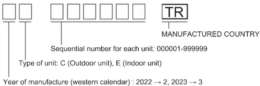
natural_image
Simple line drawing of a mechanical setup with a box and lever (no text or symbols)Fig. 2-4

natural_image
Isometric technical drawing of a modular industrial or electrical enclosure with no visible text or symbolsFig. 2-5
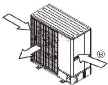
natural_image
Isometric diagram of a heat exchanger unit with airflow arrows and labeled component (B), no text or symbols present.Fig. 2-6
natural_image
Isometric line drawing of a room with a server unit and a pointer, no text or symbols present
natural_image
Isometric technical diagram of a mechanical or electrical component with labeled points A, B, and C (no text or symbols beyond labels)
Fig. 4-3
(2)

Fig. 4-5 Fig. 4-6
Fig. 7-1
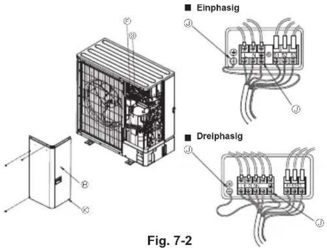
Fig. 2-2
natural_image
Simple line drawing of a mechanical setup with a box and housing (no text or symbols)Fig. 2-4

natural_image
Isometric technical drawing of a modular industrial or electrical enclosure with heat exchangers and cooling fins (no text or symbols)Fig. 2-5

natural_image
Technical line drawing of a heat exchanger unit with airflow arrows and labeled component (B), no readable text or symbols present.Fig. 2-6
natural_image
Isometric technical diagram of a mechanical or electrical component with labeled points A, B, C, E (no text or symbols beyond labels)(mm)
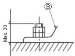
Fig. 4-3
(2)
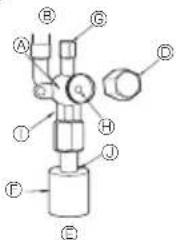
© Flexible de charge
© Ouverture de service
Fig. 4-7
natural_image
Simple line drawing of a rectangular frame with a small box on top, no text or symbols present.Fig. 2-4

natural_image
Isometric technical drawing of a modular electronic device with labeled component (A), no text or symbols present.Fig. 2-5
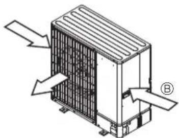
natural_image
Technical line drawing of a heat exchanger unit with airflow arrows and labeled component (B), no readable text or symbols present.Fig. 2-6
| ∅19,05 | ∅22,2 ∅25 | 4 ∅28,58 | |
| 1,0 1,0 | 1,0 1,0 |

WAARSCHUWING:
Fig. 4-3
(2)

Fig. 4-5 Fig. 4-6
natural_image
Simple line drawing of a simple room setup with a cabinet and wall (no text or symbols)Fig. 2-4

natural_image
Isometric technical drawing of a modular industrial or electrical enclosure with heat sinks and a labeled section (A), no text or symbols present.Fig. 2-5
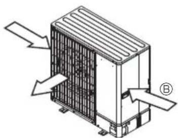
natural_image
Technical diagram of a heat exchanger unit with airflow arrows and labeled component (B), no readable text or symbols present.Fig. 2-6
natural_image
Isometric line drawing of a room with a server unit and a pointer, no text or symbols present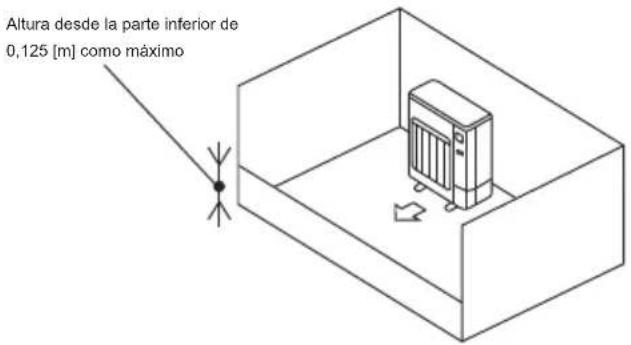
natural_image
Isometric technical diagram of a mechanical or electrical component with labeled points A, B, C, E (no text or symbols beyond labels)
Fig. 4-3
(2)

natural_image
Simple line drawing of a small room with a cabinet and wall, no text or symbols presentFig. 2-4
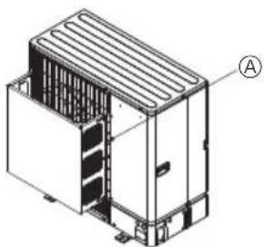
natural_image
Isometric technical drawing of a multi-chamber industrial or electrical enclosure with no visible text or symbolsFig. 2-5
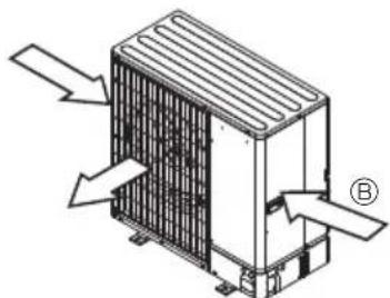
natural_image
Isometric technical diagram of a heat exchanger or cooling unit with directional arrows indicating airflow or heat flow (no text or symbols present)Fig. 2-6
natural_image
Isometric line drawing of a server room with a pointer and directional arrow, no text or symbols present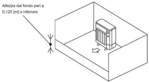
natural_image
Isometric technical diagram of a modular device with labeled components (A, B, C, E), no readable text or symbols beyond labels.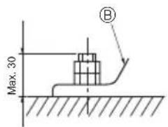
| ∅19,05 | ∅22,2 | ∅25 | 4 | ∅28,58 |
| 1,0 | 1,0 | 1,0 | 1,0 |
AVVERTENZA:
Fig. 4-3
(2)

Fig. 4-5 Fig. 4-6
natural_image
Simple line drawing of a rectangular box mounted on a platform with a small inset box, no text or symbols present.Fig. 2-4

natural_image
Isometric technical drawing of a modular electronic device with cooling fins and labeled component (A), no text or symbols present.Fig. 2-5

natural_image
Isometric technical diagram of a heat exchanger unit with directional arrows indicating airflow or heat flow (no text or labels)Fig. 2-6
natural_image
Isometric line drawing of a room with a server unit and a pointer, no text or symbols present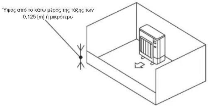
Fig. 4-3
(2)
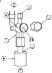
Fig. 4-5 Fig. 4-6
natural_image
Simple line drawing of a mechanical setup with a box and housing (no text or symbols)Fig. 2-4

natural_image
Isometric technical drawing of a modular industrial or electrical enclosure with heat exchangers and cooling fins (no text or symbols)Fig. 2-5

natural_image
Technical diagram of a heat exchanger unit with directional arrows indicating airflow or movement (no text or labels present)Fig. 2-6
natural_image
Isometric line drawing of a room with a server unit and directional arrow, no text or symbols present![Altura de 0,125 [m] ou menos a partir da parte inferior](/content/2026/04/733125/images/72afe2a38d3fadd73dcb752e8064938d09bec00dcdf6ece75cef46f72ac69167.jpg)
Fig. 4-3
(2)
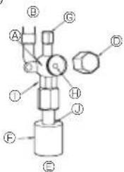
natural_image
Simple line drawing of a rectangular box mounted on a base, with no text or symbols present.Fig. 2-4

natural_image
Isometric technical drawing of a modular industrial or electrical enclosure with labeled component (A), no text or symbols present.Fig. 2-5

natural_image
Technical diagram of a heat exchanger unit with airflow arrows and labeled component (B), no readable text or symbols present.Fig. 2-6
2.4. Plads til ventilation og service
Fig. 4-3
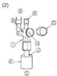
Fig. 4-5 Fig. 4-6
© Pá-stedet arrangement
© Ekstern inputadapter (PAC-SC36NA-E)
X: Relæ
© Udendørs enheds kontrolpanel
© Maks. 10 m
© Strømforsyning til relæ
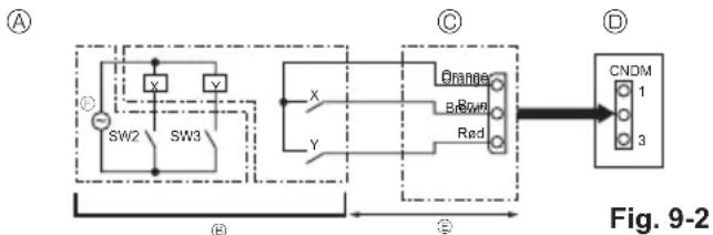
flowchart
graph LR
    A["Switch"] --> B["SW2"]
    A --> C["SW3"]
    B --> D["Orange"]
    C --> D
    D --> E["CNDM 1"]
    D --> F["CNDM 3"]
    G["Input"] --> H["Switch"]
    I["Input"] --> J["Switch"]
    K["Input"] --> L["Switch"]
    M["Input"] --> N["Switch"]
    O["Input"] --> P["Switch"]
    Q["Input"] --> R["Switch"]
    S["Input"] --> T["Switch"]
    U["Input"] --> V["Switch"]
    W["Input"] --> X["Switch"]
    Y["Input"] --> Z["Switch"]
    AA["Input"] --> AB["Switch"]
    AC["Input"] --> AD["Switch"]
    AE["Input"] --> AF["Switch"]
    AG["Input"] --> AH["Switch"]
    AI["Input"] --> AJ["Switch"]
    AK["Input"] --> AL["Switch"]
    AM["Input"] --> AN["Switch"]
    AO["Input"] --> AP["Switch"]
    AQ["Input"] --> AR["Switch"]
    AS["Input"] --> AT["Switch"]
    AU["Input"] --> AV["Switch"]
    AW["Input"] --> AX["Switch"]
    AY["Output"] --> AZ["Output"]
© På-stedet arrangement
X, Y: Relæ
© Ekstern inputadapter (PAC-SC36NA-E)
⑬ Udendørs enheds kontrolpanel
© Maks. 10 m
© Strømforsyning til relæ
natural_image
Simple line drawing of a rectangular box mounted on a base, with a small protrusion on top (no text or symbols)Fig. 2-4

natural_image
Isometric technical drawing of a modular industrial or electrical enclosure with labeled component (A), no text or symbols present.Fig. 2-5
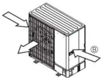
natural_image
Technical diagram of a heat exchanger unit with airflow arrows and labeled component (B), no readable text or symbols present.Fig. 2-6
natural_image
Isometric line drawing of a room with a server unit and a pointer, no text or symbols present| ∅19,05 | ∅22,2 | ∅25 | 4 | ∅28,58 |
| 1,0 | 1,0 | 1,0 | 1,0 |

WARNING:
Fig. 4-3
(2)
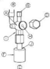
Fig. 7-1

natural_image
Simple line drawing of a rectangular box mounted on a platform, with no text or symbols present.Fig. 2-4

natural_image
Isometric technical drawing of a modular industrial or electrical enclosure with cooling fins and internal compartments (no text or symbols)Fig. 2-5
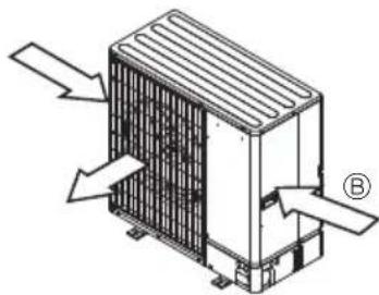
natural_image
Isometric diagram of a heat exchanger unit with airflow arrows and labeled component (B), no text or symbols present.Fig. 2-6
natural_image
Isometric line drawing of a server room with a pointer and directional arrow, no text or symbols presentFig. 4-3
④ Fremre rørdeksel
① Bakre rørdeksel
① Stengeventil
① Servicepanel
© Bøyradius : 100 mm - 150 mm
4.3. Kjølemiddelrør (Fig. 4-3)
Fjern servicepanelet ① (4 skruer) og det fremre rørdekselet ⑧ (2 skruer), samt det bakre rørdekselet ⑥ (4 skruer).
(2)

Fig. 4-5 Fig. 4-6
Fig. 7-1
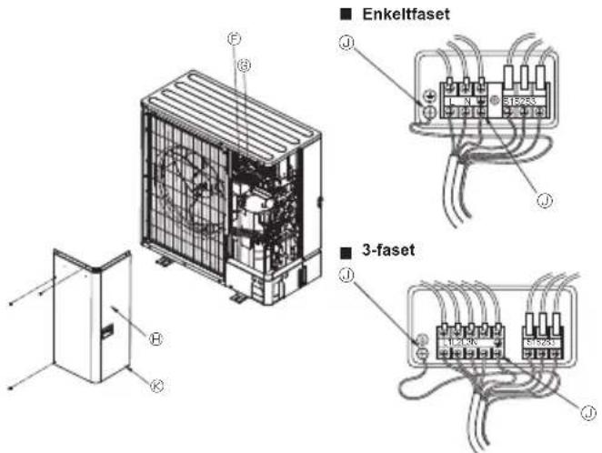
Fig. 7-2
© Ekstern inngangsadapter (PAC-SC36NA-E)
X: Relé
natural_image
Simple line drawing of a rectangular box mounted on a platform, with no text or symbols present.Fig. 2-4

natural_image
Isometric technical drawing of a modular industrial or electrical enclosure with labeled component (A), no text or symbols present.Fig. 2-5

natural_image
Technical line drawing of a heat exchanger unit with airflow arrows and labeled component B (no text or symbols beyond labels)Fig. 2-6
natural_image
Isometric line drawing of a server room with a pointer and directional arrow, no text or symbols presentFig. 4-3
(2)

natural_image
Simple line drawing of a simple room setup with a small cabinet and a wall-mounted fixture (no text or symbols)Fig. 2-4
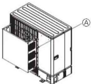
natural_image
Isometric technical drawing of a modular industrial or electrical enclosure with labeled component A (no text or symbols beyond label)Fig. 2-5
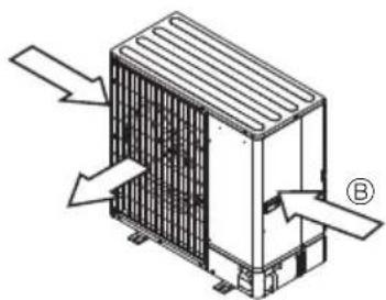
natural_image
Technical line drawing of a heat exchanger unit with directional arrows indicating airflow or heat flow (no text or symbols)Fig. 2-6
natural_image
Isometric line drawing of a room with a server unit and a pointer, no text or symbols present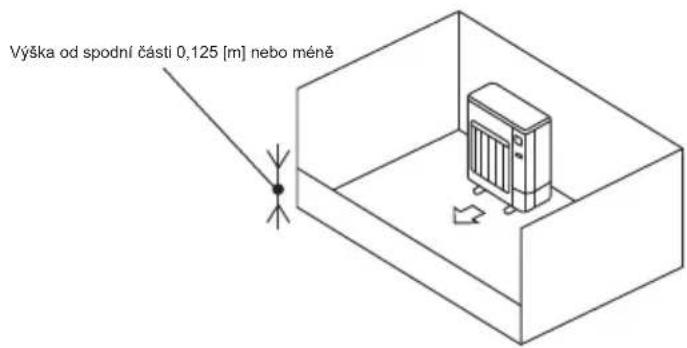
Fig. 4-3
chemical
Two chemical molecular structures labeled (1) and (2), showing atoms and bonds with numbered positionsFig. 4-5 Fig. 4-6
natural_image
Simple line drawing of a rectangular box mounted on a platform, with no text or symbols present.Fig. 2-4

natural_image
Isometric technical drawing of a modular industrial or electrical enclosure with labeled component (A), no text or symbols present.Fig. 2-5

natural_image
Technical line drawing of a heat exchanger unit with airflow arrows and labeled component (B), no readable text or symbols present.Fig. 2-6
| ∅19,05 | ∅22,2 | ∅25 | 4 | ∅28,58 |
| 1,0 | 1,0 | 1,0 | 1,0 |
OSTRZEŻENIE:
Fig. 4-3
(2)

Fig. 4-5 Fig. 4-6
natural_image
Simple line drawing of a rectangular box mounted on a platform, with no text or symbols present.Fig. 2-4

natural_image
Isometric technical drawing of a modular industrial or electrical enclosure with labeled component (A), no text or symbols present.Fig. 2-5
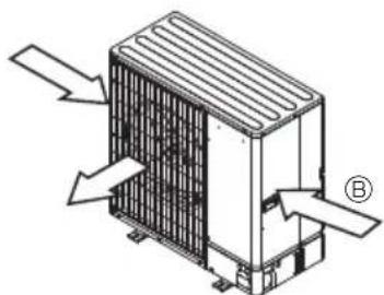
natural_image
Technical line drawing of a heat exchanger or cooling unit with directional arrows indicating airflow or heat flow (no text or symbols present)Fig. 2-6
natural_image
Isometric line drawing of a room with a heater and a pointer, no text or symbols presentFig. 4-3
(2)
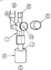
line
| Ekvivalentna dljikina on trboprovoda [m] | Koefficient on energy-effectiveness | |---|---| | 01020304050 | 1.0 | | 01020304050 | 0.98 | | 01020304050 | 0.96 | | 01020304050 | 0.94 | | 01020304050 | 0.92 | | 01020304050 | 0.90 | | 01020304050 | 0.88 | | 01020304050 | 0.86 | The chart displays a single dashed line representing a decreasing trend in Koefficient on energy-effectiveness as the Ekvivalentna dljikina on trboprovoda increases from 1 to 7 meters. The label 'Размер на тръбата за газ: ø15,88 и ø12,7' indicates the parameter value for this data point. The x-axis is labeled 'Еквивалентна длжина на тръбопровода [m]', and the y-axis is unlabeled but corresponds to the coefficient values shown at each data point. The chart visually represents a negative correlation between the variables.natural_image
Simple line drawing of a rectangular box mounted on a base, with a small protrusion on top (no text or symbols)Fig. 2-4
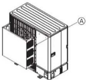
natural_image
Isometric technical drawing of a modular industrial or electrical enclosure with labeled component (A), no text or symbols present.Fig. 2-5

natural_image
Technical diagram of a heat exchanger unit with directional arrows indicating airflow or movement (no text or labels present)Fig. 2-6
2.4. Priestor na vetranie a servis
natural_image
Isometric line drawing of a room with a server unit and a pointer, no text or symbols present![Výška od dna maximálne 0,125 [m]](/content/2026/04/733125/images/0093b22fbe9929fbc1802b18a1340694f3e30a5dcb39e00b760786839a5410a1.jpg)
Fig. 4-3
(2)

Fig. 4-5 Fig. 4-6
④ Teleso ventilu
⑧ Strana jednotky
© Rukovät
© Viečko
© Strana miestneho potrubia
© Kryt potrubia
© Servisný port
Driek ventilu
natural_image
Simple line drawing of a rectangular box mounted on a base, with a small inset showing a cylindrical object (no text or symbols)Fig. 2-4

natural_image
Isometric technical drawing of a modular industrial or electrical enclosure with labeled component (A), no text or symbols present.Fig. 2-5
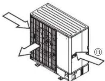
natural_image
Technical line drawing of a heat exchanger unit with airflow arrows and labeled component (B), no readable text or symbols present.Fig. 2-6
natural_image
Isometric line drawing of a room with a central storage unit and a pointer, no text or symbols present| ∅19,05 | ∅22,2 ∅25 | 4 ∅28,58 | |
| 1,0 | 1,0 | 1,0 | 1,0 |
FIGYELMEZTETÉS:
Fig. 4-3
(2)

Fig. 4-5 Fig. 4-6
natural_image
Simple line drawing of a mechanical setup with a box and lever (no text or symbols)Fig. 2-4
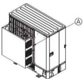
natural_image
Isometric technical drawing of a modular industrial or electrical unit with heat exchangers and cooling fins (no text or symbols)Fig. 2-5
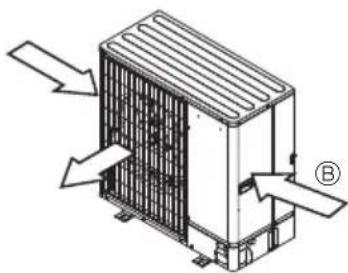
natural_image
Isometric technical diagram of a heat exchanger unit with directional arrows indicating airflow or heat flow (no text or labels)Fig. 2-6
2.4. Prostor za prezračevanje in servisiranje
Fig. 4-3
④ Sprednji pokrov cevi
⑤ Zadnji pokrov cevi
© Zaporni ventil
⑭ Servisna plošča
① Koleno s polmerom: 100–150 mm
4.3. Napeljava hladiva (Fig. 4-3)
Odstranite servisno ploščo ① (4 vijaki), sprednji pokrov cevi ② (2 vijaka) in zadnji pokrov cevi ③ (4 vijaki).
(2)

Fig. 4-5 Fig. 4-6
④ Ohišje ventila
⑧ Stran enote
© Ročaj
Pokrovček
© Stran lokalne cevi
© Obloga cevi
© Servisni priključek
Steblo ventila
* Slika na levi je le primer.
Fig. 2-2
natural_image
Simple line drawing of a mechanical setup with a box and housing (no text or symbols)Fig. 2-4

natural_image
Isometric technical drawing of a modular industrial or electrical enclosure with labeled component (A), no text or symbols present.Fig. 2-5

natural_image
Technical diagram of a heat exchanger unit with airflow arrows and labeled component (B), no readable text or symbols present.Fig. 2-6
natural_image
Isometric line drawing of a room with a heater and a small object near the top, no text or symbols present.Fig. 4-3
(2)

Fig. 4-5 Fig. 4-6
line
| Lungime echivalentă conducte [m] | Rată capacitate | | ------------------------------- | --------------- | | 0.1020304050 | 1.0 | | (labeled point) | 0.98 | | (labeled point) | 0.96 | | (labeled point) | 0.94 | | (labeled point) | 0.92 | | (labeled point) | 0.90 | | (labeled point) | 0.88 | | (labeled point) | 0.86 | | (labeled point) | 0.84 | | (labeled point) | 0.82 | | (labeled point) | 0.80 | | (labeled point) | 0.78 | | (labeled point) | 0.76 | | (labeled point) | 0.74 | | (labeled point) | 0.72 | | (labeled point) | 0.70 |PUZ-SWM120
PUZ-SHWM120
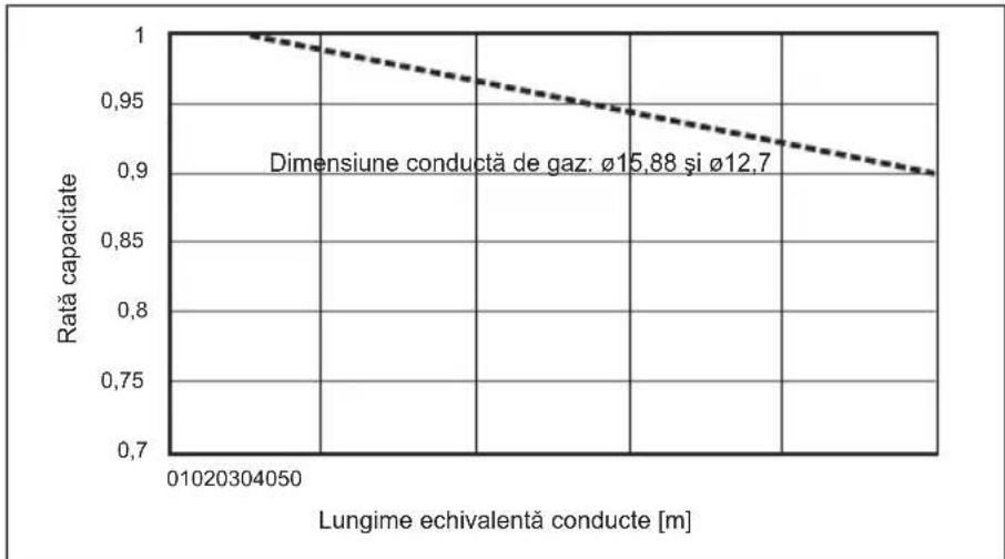
line
| Lungime echivalentă conducte [m] | Rată capacitate | | ------------------------------- | --------------- | | 0 | 1.0 | | 400 | 0.98 | | 800 | 0.96 | | 1200 | 0.94 | | 1600 | 0.92 | | 2000 | 0.90 |PUZ-SWM140
PUZ-SHWM140
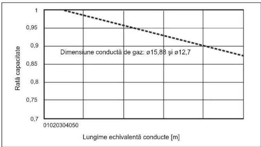
line
| Lungime echivalentă conducte [m] | Rată capacitate | | ------------------------------- | --------------- | | 0.10 | 1.0 | | 0.30 | 0.95 | | 0.50 | 0.92 | | 0.70 | 0.88 || SW7-1 SW2 SW3 Consum de energie | ||||
| Funcția la cerere | ON (PORNIT) | OFF (OPRIT) | OFF (OPRIT) | 100% |
| ON (PORNIT) | OFF (OPRIT) | 75% | ||
| ON (PORNIT) | ON (PORNIT) | 50% | ||
| OFF (OPRIT) | ON (PORNIT) | 0% (Stop) | ||
| SW1 Setare | Adresă agent frigorific |
| ON (PORNIT)OFF (CPRIT)3 4 5 6 7 | |
| ON (PORNIT)OFF (CPRIT)3 4 5 6 7 | 00 |
| ON (PORNIT)OFF (CPRIT)3 4 5 6 7 | 01 |
| ON (PORNIT)OFF (CPRIT)3 4 5 6 7 | 02 |
| SW1 Setare | Adresă agent frigorific |
| ON : PORNIT OFF (OPRIT) 3 4 5 6 7 | 03 |
| ON : PORNIT OFF (OPRIT) 3 4 5 6 7 | 04 |
| ON : PORNIT OFF (OPRIT) 3 4 5 6 7 | 05 |
Notă:
natural_image
Simple line drawing of a mechanical setup with a box and housing (no text or symbols)Fig. 2-4

natural_image
Isometric technical drawing of a modular industrial or electrical enclosure with heat exchangers and cooling fins (no text or symbols)Fig. 2-5

natural_image
Technical diagram of a heat exchanger unit with airflow arrows and labeled component (B), no readable text or symbols present.Fig. 2-6
natural_image
Isometric line drawing of a room with a server unit and a pointer, no text or symbols presentFig. 4-3
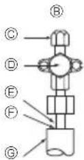
© Kohalik toru
© Suletud, samamoodi gaasi poolega
⑬ Toru kate
Fig. 4-4
(1)
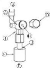
(2)

natural_image
Simple line drawing of a mechanical setup with a box and lever (no text or symbols)Fig. 2-4

natural_image
Isometric technical drawing of a modular industrial or electrical enclosure with no visible text or symbolsFig. 2-5

natural_image
Technical diagram of a heat exchanger unit with airflow arrows and labeled component (B), no readable text or symbols present.Fig. 2-6
natural_image
Isometric line drawing of a room with a server unit and a pointer, no text or symbols presentFig. 4-3
(2)

Fig. 4-5 Fig. 4-6
natural_image
Simple line drawing of a rectangular box mounted on a flat base, with no text or symbols present.Fig. 2-4
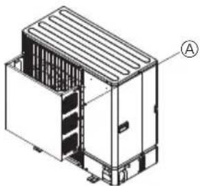
natural_image
Isometric technical drawing of a multi-chamber industrial or electrical enclosure with no visible text or symbolsFig. 2-5
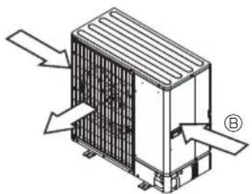
natural_image
Isometric diagram of a heat exchanger unit with airflow arrows and labeled component B (no text or symbols beyond labels)Fig. 2-6
natural_image
Isometric line drawing of a room with a server unit and a pointer, no text or symbols present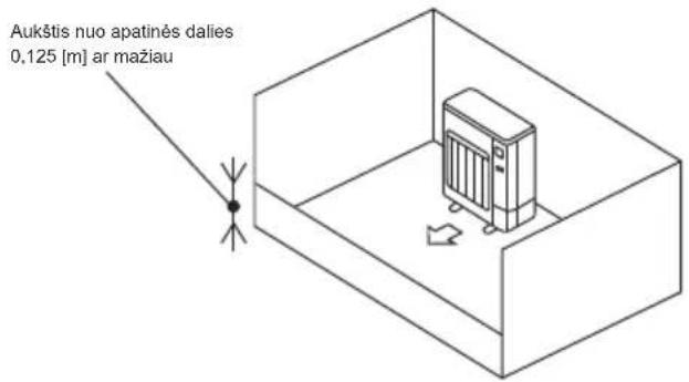
Fig. 4-3
(2)

Fig. 4-5 Fig. 4-6
flowchart
graph LR
    A["SW1"] -->|X| B["Oranžine Ruda"]
    B --> C["CNDM"]
    style A fill:#f9f,stroke:#333
    style B fill:#ccf,stroke:#333
    style C fill:#cfc,stroke:#333
    subgraph Section A
        A1["①"] --> A2["②"]
        A2 --> A3["③"]
    end
    subgraph Section B
        B1["X"] --> B2["Raudona"]
    end
    subgraph Section C
        C1["④"] --> C2["CNDM"]
        C2 --> C3["⑤"]
    end
    style A fill:#f9f,stroke:#333
    style B fill:#ccf,stroke:#333
    style C fill:#cfc,stroke:#333
    style D fill:#fcc,stroke:#333
    note right of B: X (X) to its left of C
    note right of C: Ruda to its right of C
    note right of D: CNDM to its right of C
    note right of D: Fig. 9-1
natural_image
Simple line drawing of a mechanical setup with a box and housing (no text or symbols)Fig. 2-4

natural_image
Isometric technical drawing of a modular electronic device with labeled component A (no text or symbols beyond label)Fig. 2-5
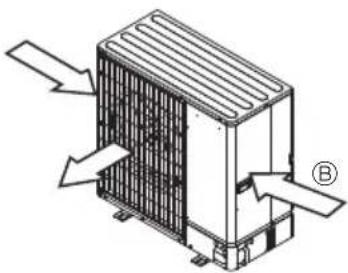
natural_image
Isometric technical diagram of a heat exchanger unit with directional arrows indicating airflow or heat flow (no text or symbols present)Fig. 2-6
2.4. Provjetravanje i servisni prostor
2.4.1. Postavljanje na vjetrovitom mjestu
natural_image
Isometric line drawing of a room with a server unit and a pointer, no text or symbols present![Visina od donjeg dijela je 0,125 [m] ili manje](/content/2026/04/733125/images/54b62118383ae5dc5d58da4ba105bab035973cfa4d21a8cabd72ff186757f41a.jpg)
C) Osigurajte otvoren prostor s pravilnim provjetravanjem.
Pripazite da širina otvorenog prostora bude 0,9 [m] ili više, a njegova visina 0,15 [m] ili više.
Fig. 4-3
Ⓐ Prednji dio poklopca cijevi
⑤ Stražnji dio poklopca cijevi
© Zaporni ventil
⑭ Servisna ploča
④ Polumjer zavoja: 100 mm – 150 mm
4.3. Cijevi za rashladno sredstvo (Fig. 4-3)
Uklonite servisnu ploču (4 vijka) i prednji dio poklopca cijevi (2 vijka) i stražnji dio poklopca cijevi (4 vijka).
- Prašak koji se ljušti s nekih gumenih nosača neće uzrokovati probleme prilikom korištenja vanjske jedinice.
- Ne dopustite da cijev rashladnog sredstva dođe u kontakt s osnovnom pločom. Prijenos vibracija s vanjske jedinice na unutarnju jedinicu može uzrokovati zvukove.
① Izvedite spajanja cijevi rashladnog sredstva za unutarnju/vanjsku jedinicu kada je zaporni ventil vanjske jedinice u potpunosti zatvoren.
(2)

Fig. 4-5 Fig. 4-6
④ Tijelo ventila
⑧ Strana jedinice
© Ručka
© Poklopac
© Strana lokalne cijevi
© Poklopac cijevi
© Servisni priključak
© Tučak ventila
① Dio s dvostrukim ključem
(Ne upotrebljavajte ključ osim u ovom dijelu. Mogli
biste prouzročiti curenje rashladnog sredstva).
Brveni dio
(Zabrtvite kraj materijala toplinske izolacije na dije - lu spoja cijevi bilo kojim brtvenim materijalom koji vam je pri ruci na način da voda ne uđe u materijal toplinske izolacije.)
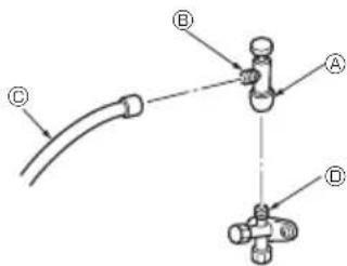
Za napajanje
Ⓐ Unutamja jedinica
natural_image
Simple line drawing of a rectangular box placed on a flat base with a small object on top (no text or symbols)Fig. 2-4

natural_image
Isometric technical drawing of a modular industrial or electrical enclosure with internal compartments and mounting brackets (no text or symbols)Fig. 2-5
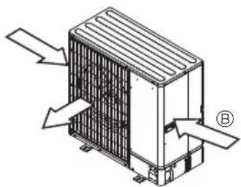
natural_image
Technical line drawing of a heat exchanger unit with directional arrows indicating airflow or heat flow (no text or symbols)Fig. 2-6
2.4. Prostor za ventilaciju i servisiranje
2.4.1. Montaža na vetrovitom mestu
Kod montaže spoljne jedinice na krovu ili drugoj lokaciji koja nije zaštićena od vetra, postavite odvod vazduha iz jedinice tako da ne bude direktno izložen jakim vetrovima. Jak vetar koji ulazi u odvod vazduha može ometati normalan protok vazduha i može doći do kvara.
U nastavku su prikazana tri primera predostrožnosti protiv jakih vetrova.
natural_image
Isometric line drawing of a room with a server unit and a pointer, no text or symbols present![Visina od dna 0,125 [m] ili manja](/content/2026/04/733125/images/6ccc3381024b1f5aac425fa4b7d5189a8c302e5d8393efb34478ee7d6494862a.jpg)
Fig. 4-2
4.2. Cevi za priključivanje (Fig. 4-1)
- Prilikom korišćenja komercijalno dostupnih bakarnih cevi, obložite cevi za tečnost i gas komercijalno dostupnim izolacionim materijalima (toplotno otporan na 110 °C ili više, debljina 12 mm ili više). Direktan kontakt sa golom cevi može izazvati opekotine ili promrzline.
- Pre nego što pričvrstite proširenu navrtku nanesite tanak sloj rashladnog ulja na površinu sedišta cevi i spojnica. Ⓔ
• Nanesite rashladno mašinsko ulje na celu površinu proširenog sedišta. ③ - Koristite proširene navrtke za sledeću veličinu cevi. ©
- Prilikom spajanja prvo poravnajte centar, a zatim rukom pritegnite prva 3 do 4 okreta proširene navrtke.
- Pomoću 2 ključa pritegnite priključke za cevi. ©
- Koristite detektor curenja ili sapunicu da biste videli da li ima curenja gasa nakon povezivanja.
| SWM60 - 140, SHWM60 - 140 | ||
| Strana gasa V | veličina cevi (mm) ø1 | 2,7 ili ø15,88 |
| Strana tečnosti | Veličina cevi (mm) ø6,35 | |
- Kod savijanja cevi, vodite računa da ih ne slomite. Dovoljan je radijus savijanja od 100 mm do 150 mm.
- Vodite računa da cevi ne dođu u kontakt sa kompresorom i osnovnom pločom kompresora. Može se pojaviti abnormalna buka ili vibracija.
① Povezivanje cevi se mora započeti na strani unutrašnje jedinice.
Proširene navrtke se moraju pritegnuti moment-ključem.
② Proširite cevi za tečnost i cevi za gas i nanesite tanak sloj rashladnog ulja (nanosi se na licu mesta). - Kada se koristi uobičajeno zaptivanje cevi, pogledajte Tabelu 1 za proširivanje cevi za rashladno sredstvo R32.
Merač za podešavanje veličine se može koristiti za potvrdu A izmerenih vrednosti.
Tabela 1 (Fig. 4-2)
| Bakarna cev spoljni prečnik (mm) | A (mm) |
| Alat za proširivanje za R32 | |
| Tip sa stezaljkom | |
| ø6,35 (1/4") | 0 - 0,5 |
| ø9,52 (3/8") | 0 - 0,5 |
| ø12,7 (1/2") | 0 - 0,5 |
| ø15,88 (5/8") | 0 - 0,5 |
| ø19,05 (3/4") | 0 - 0,5 |

UPOZORENJE:
Prilikom montaže jedinice, čvrsto spojite cevi za rashladnu tečnost pre nego što pokrenete kompresor.
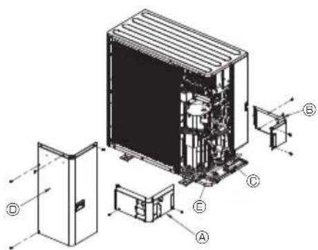
Fig. 4-3
Ⓐ Prednji poklopac za cevi
© Zadnji poklopac za cevi
© Zaustavni ventil
⑪ Ploča za servisiranje
© Ugao savijanja: 100 mm–150 mm
4.3. Cevi za rashladnu tečnost (Fig. 4-3)
Skinite ploču za servisiranje ^1 (4 zavrtnja), prednji poklopac za cevi ^2 (2 zavrtnja) i zadnji poklopac za cevi ^3 (4 zavrtnja).
(2)
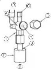
Fig. 4-5 Fig. 4-6
④ Telo ventila
⑧ Strana jedinice
© Ručka
Poklopac
© Strana lokalne cevi
© Poklopac za cev
© Servisni priključak
Vreteno ventila
* Slika na levoj strani je data samo kao primer. Oblik zaustavnog ventila, položaj servisnog priključka, itd., mogu se razlikovati u zavisnosti od modela.
* Samo okrenite Ⓐ deo.
(Nemojte dalje zatezati delove Ⓐ i Ⓑ zajedno.)
© Crevo za punjenje
hereby declares under its sole responsibility that the air conditioner(s) and heat pump(s) for use in residential, commercial, and light-industrial environments described below:
2006/42/EC: Machinery Directive
2014/30/EU: Electromagnetic Compatibility Directive
2009/125/EC: Energy-related Products Directive and Regulation (EU) No 813/2013
2011/65/EU, (EU) 2015/863 and (EU) 2017/2102: RoHS Directive
2014/68/EU: Pressure Equipment Directive
Issued: 31 January 2023 Kenichi SAITO
TURKEY Manager, Quality Assurance Department
MITSUBISHI ELECTRIC AIR CONDITIONING SYSTEMS MANUFACTURING TURKEY JOINT STOCK COMPANY Manisa OSB 4.Kisim Kecilikoyosb Mah. Ahmet Nazif Zorlu Bulvari No;19 Yunusemre – Manisa, Turkey
hereby declares under its sole responsibility that the air conditioner(s) and heat pump(s) for use in residential, commercial, and light-industrial environments described below:
MITSUBISHI ELECTRIC, PUZ-SWM60VAA*, PUZ-SWM80VAA*, PUZ-SWM100VAA*, PUZ-SWM120VAA*, PUZ-SWM140VAA*, PUZ-SHWM60VAA*, PUZ-SHWM80VAA*, PUZ-SHWM100VAA*, PUZ-SHWM120VAA*, PUZ-SHWM140VAA*, PUZ-SWM80YAA*, PUZ-SWM100YAA*, PUZ-SWM120YAA*, PUZ-SWM140YAA*, PUZ-SHWM80YAA*, PUZ-SHWM100YAA*, PUZ-SHWM120YAA*, PUZ-SHWM140YAA*, * : , 1, 2, 3, ***, 9
is/are in conformity with provisions of the following UK legislation.
The Electrical Equipment (Safety) Regulations 2016
The Supply of Machinery (Safety) Regulations 2008
The Electromagnetic Compatibility Regulations 2016
The Pressure Equipment (Safety) Regulations 2016
The Restriction of the Use of Certain Hazardous Substances in Electrical and Electronic Equipment Regulations 2012
The Ecodesign for Energy-Related Products Regulations 2010
Issued: 31 January 2023 Kenichi SAITO
TURKEY Manager, Quality Assurance Department
English is original. The other languages versions are translation of the original.

CAUTION
- Refrigerant leakage may cause suffocation. Provide ventilation in accordance with EN378-1.
- Be sure to wrap insulation around the piping. Direct contact with the bare piping may result in burns or frostbite.
- Never put batteries in your mouth for any reason to avoid accidental ingestion.
- Battery ingestion may cause choking and/or poisoning.
- Install the unit on a rigid structure to prevent excessive operation sound or vibration.
- The A-weighted sound pressure level is below 70dB.
- This appliance is intended to be used by expert or trained users in shops, in light industry and on farms, or for commercial use by lay persons.
natural_image
Isometric diagram of a device with a 100x magnified view, no text or symbols present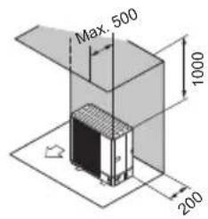
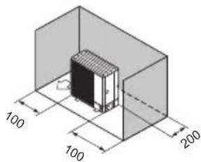
natural_image
Isometric diagram of a mechanical component with dimension annotations (100 and 200 units) and no readable text or symbols.Fig. 2-7 Fig. 2-8 Fig. 2-9
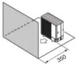
natural_image
Isometric diagram of a mechanical component with dimension标注 (no text or symbols)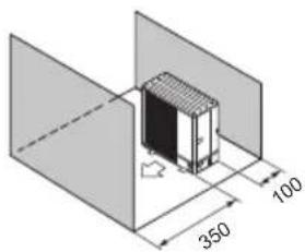

Fig. 2-10 Fig. 2-11 Fig. 2-12
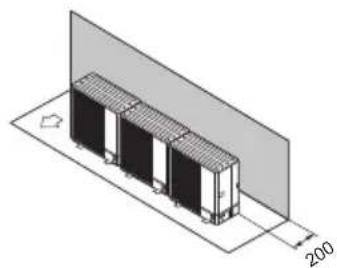
natural_image
Isometric diagram of a multi-story industrial or storage unit with a 200-unit dimension label, no text or symbols present.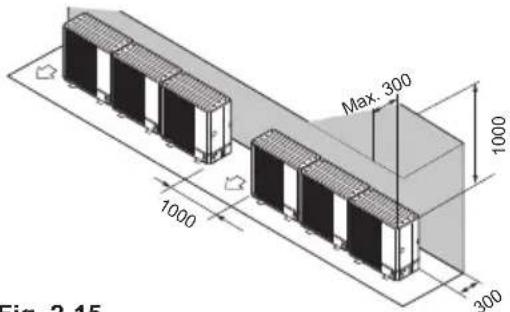
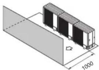
natural_image
Isometric diagram of a multi-layered industrial or mechanical component with a 1000-unit dimension label (no text or symbols beyond the scale)Fig. 2-13 Fig. 2-14 Fig. 2-15
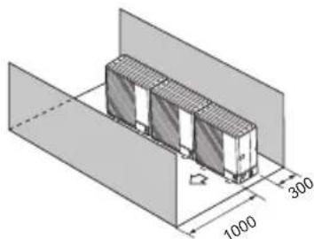
natural_image
Isometric technical drawing of a mechanical component with dimension annotations (1000, 300, and 1000 units), no readable text or symbols beyond measurement labels.Fig. 2-16 Fig. 2-17
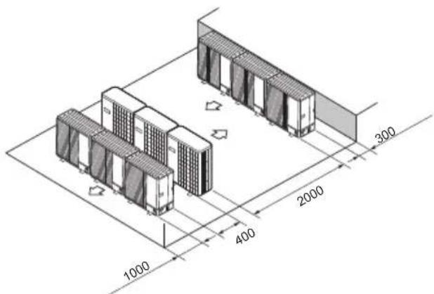
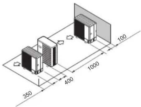
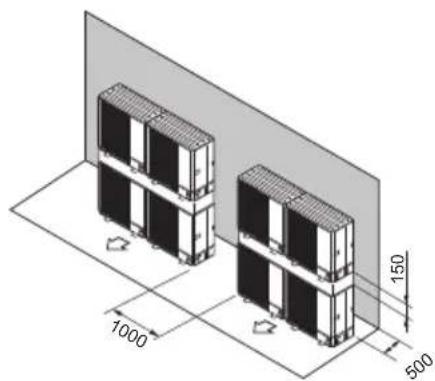
natural_image
Isometric diagram of two stacked electronic components with dimension annotations (1000, 500, 150) and a gray panel background (no text or symbols beyond measurement labels)Fig. 2-18 Fig. 2-19
Please be sure to put the contact address/telephone number on this manual before handing it to the customer.

- Air to Water Heat Pump
- PUZ-SWM • AA series / PUZ-SHWM • AA series
- INSTALLATION MANUAL
- INSTALLATIONSHANDBUCH
- MANUEL D'INSTALLATION
- CAUTION:
- Safety precautions
- WARNING:
- Before installation
- Before installation (relocation)
- Before electric work
- Before starting the test run
- Using R32 refrigerant outdoor units
- The following checks shall be applied to installations using flammable refrigerants:
- Initial safety checks shall include that:
- Refrigerant pipe (Fig. 2-1)
- Choosing the outdoor unit installation location
- Outline dimensions (Outdoor unit) (Fig. 2-3)
- Ventilation and service space
- Windy location installation
- When installing a single outdoor unit (Refer to the last page)
- When installing multiple outdoor units (Refer to the last page)
- Installation location
- ◎2.5. Minimum installation area
- Installing the outdoor unit
- Precautions for devices that use R32 refrigerant
- Installing the refrigerant piping
- Connecting pipes (Fig. 4-1)
- Refrigerant piping (Fig. 4-3)
- Refrigerant pipe airtight testing method (Fig. 4-4)
- Stop valve opening method
- Precautions when using the charge valve (Fig. 4-7)
- Addition of refrigerant
- Drainage piping work
- Water piping work
- Minimum water quantity
- Available range (Water flow rate, return water temp.)
- Correcting capacity for changes in the length and diameter of refrigerant pipe
- Electrical work
- Outdoor unit (Fig. 7-1, Fig. 7-2)
- Note:
- Test run
- Before test run
- Insulation resistance
- Test run
- Using remote controller
- Special Functions
- Low noise mode (on-site modification) (Fig. 9-1)
- Using the CNDM connector (Option)
- Using remote controller
- Demand function (on-site modification) (Fig. 9-2)
- Refrigerant collecting (pump down)
- System control
- Specifications
- Serial number
- ■ The serial number is indicated on the SPEC NAME PLATE.
- WAARSCHUWING:
- AVVERTENZA:
- Plads til ventilation og service
- Kjølemiddelrør (Fig. 4-3)
- OSTRZEŻENIE:
- Priestor na vetranie a servis
- FIGYELMEZTETÉS:
- Prostor za prezračevanje in servisiranje
- Napeljava hladiva (Fig. 4-3)
- Provjetravanje i servisni prostor
- Postavljanje na vjetrovitom mjestu
- Cijevi za rashladno sredstvo (Fig. 4-3)
- Prostor za ventilaciju i servisiranje
- Montaža na vetrovitom mestu
- Cevi za priključivanje (Fig. 4-1)
- UPOZORENJE:
- Cevi za rashladnu tečnost (Fig. 4-3)
- CAUTION
Brand : MITSUBISHI
Model : Ecodan PUZ-SWM100VAA
Category : Air-conditioner