USER MANUAL MSZ-DM35VA MITSUBISHI
Air-Conditioners OUTDOOR UNIT
MXZ-8A140VA

A446
INSTALLATION MANUAL
FOR INSTALLER
For safe and correct use, please read this installation manual thoroughly before installing the air-conditioner unit.
INSTALLATIONSHANDBUCH
FÜR INSTALLATEURE
MANUEL D'INSTALLATION
POUR L'INSTALLATEUR
- Safety precautions 2
- Installation diagram & parts 3
- Installation location 4
- Installing the outdoor unit 6
-
Installing the refrigerant piping 6
-
Drainage piping work 10
- Electrical work 10
8.Test run 14
- Special Functions 15
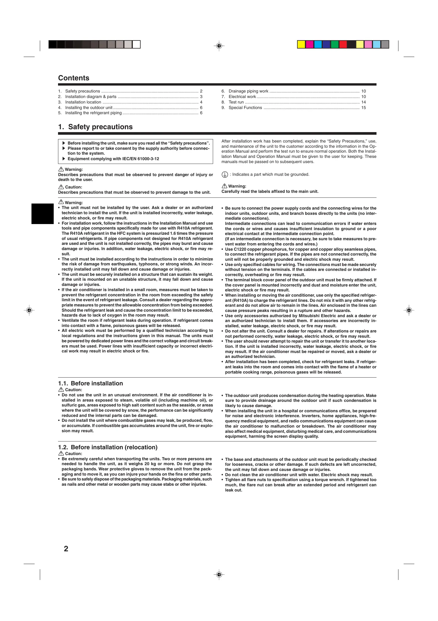
1. Safety precautions
Before installing the unit, make sure you read all the "Safety precautions".
Please report to or take consent by the supply authority before connection to the system.
Equipment complying with IEC/EN 61000-3-12
Warning:
Describes precautions that must be observed to prevent danger of injury or death to the user.
Caution:
Describes precautions that must be observed to prevent damage to the unit.
After installation work has been completed, explain the "Safety Precautions," use, and maintenance of the unit to the customer according to the information in the Operation Manual and perform the test run to ensure normal operation. Both the Installation Manual and Operation Manual must be given to the user for keeping. These manuals must be passed on to subsequent users.
12 : Indicates a part which must be grounded.
Warning:
Carefully read the labels affixed to the main unit.
Warning:
- The unit must not be installed by the user. Ask a dealer or an authorized technician to install the unit. If the unit is installed incorrectly, water leakage, electric shock, or fire may result.
- For installation work, follow the instructions in the Installation Manual and use tools and pipe components specifically made for use with R410A refrigerant. The R410A refrigerant in the HFC system is pressurized 1.6 times the pressure of usual refrigerants. If pipe components not designed for R410A refrigerant are used and the unit is not installed correctly, the pipes may burst and cause damage or injuries. In addition, water leakage, electric shock, or fire may result.
- The unit must be installed according to the instructions in order to minimize the risk of damage from earthquakes, typhoons, or strong winds. An incorrectly installed unit may fall down and cause damage or injuries.
- The unit must be securely installed on a structure that can sustain its weight. If the unit is mounted on an unstable structure, it may fall down and cause damage or injuries.
- If the air conditioner is installed in a small room, measures must be taken to prevent the refrigerant concentration in the room from exceeding the safety limit in the event of refrigerant leakage. Consult a dealer regarding the appropriate measures to prevent the allowable concentration from being exceeded. Should the refrigerant leak and cause the concentration limit to be exceeded, hazards due to lack of oxygen in the room may result.
- Ventilate the room if refrigerant leaks during operation. If refrigerant comes into contact with a flame, poisonous gases will be released.
-
All electric work must be performed by a qualified technician according to local regulations and the instructions given in this manual. The units must be powered by dedicated power lines and the correct voltage and circuit breakers must be used. Power lines with insufficient capacity or incorrect electrical work may result in electric shock or fire.
-
Be sure to connect the power supply cords and the connecting wires for the indoor units, outdoor units, and branch boxes directly to the units (no intermediate connections).
Intermediate connections can lead to communication errors if water enters the cords or wires and causes insufficient insulation to ground or a poor electrical contact at the intermediate connection point.
(If an intermediate connection is necessary, be sure to take measures to prevent water from entering the cords and wires.)
- Use C1220 copper phosphorus, for copper and copper alloy seamless pipes, to connect the refrigerant pipes. If the pipes are not connected correctly, the unit will not be properly grounded and electric shock may result.
- Use only specified cables for wiring. The connections must be made securely without tension on the terminals. If the cables are connected or installed incorrectly, overheating or fire may result.
- The terminal block cover panel of the outdoor unit must be firmly attached. If the cover panel is mounted incorrectly and dust and moisture enter the unit, electric shock or fire may result.
- When installing or moving the air conditioner, use only the specified refrigerant (R410A) to charge the refrigerant lines. Do not mix it with any other refrigerant and do not allow air to remain in the lines. Air enclosed in the lines can cause pressure peaks resulting in a rupture and other hazards.
- Use only accessories authorized by Mitsubishi Electric and ask a dealer or an authorized technician to install them. If accessories are incorrectly installed, water leakage, electric shock, or fire may result.
- Do not alter the unit. Consult a dealer for repairs. If alterations or repairs are not performed correctly, water leakage, electric shock, or fire may result.
- The user should never attempt to repair the unit or transfer it to another location. If the unit is installed incorrectly, water leakage, electric shock, or fire may result. If the air conditioner must be repaired or moved, ask a dealer or an authorized technician.
- After installation has been completed, check for refrigerant leaks. If refrigerant leaks into the room and comes into contact with the flame of a heater or portable cooking range, poisonous gases will be released.
1.1. Before installation
Caution:
- Do not use the unit in an unusual environment. If the air conditioner is installed in areas exposed to steam, volatile oil (including machine oil), or sulfuric gas, areas exposed to high salt content such as the seaside, or areas where the unit will be covered by snow, the performance can be significantly reduced and the internal parts can be damaged.
-
Do not install the unit where combustible gases may leak, be produced, flow, or accumulate. If combustible gas accumulates around the unit, fire or explosion may result.
-
The outdoor unit produces condensation during the heating operation. Make sure to provide drainage around the outdoor unit if such condensation is likely to cause damage.
- When installing the unit in a hospital or communications office, be prepared for noise and electronic interference. Inverters, home appliances, high-frequency medical equipment, and radio communications equipment can cause the air conditioner to malfunction or breakdown. The air conditioner may also affect medical equipment, disturbing medical care, and communications equipment, harming the screen display quality.
1.2. Before installation (relocation)
Caution:
- Be extremely careful when transporting the units. Two or more persons are needed to handle the unit, as it weighs 20kg or more. Do not grasp the packaging bands. Wear protective gloves to remove the unit from the packaging and to move it, as you can injure your hands on the fins or other parts.
-
Be sure to safely dispose of the packaging materials. Packaging materials, such as nails and other metal or wooden parts may cause stabs or other injuries.
-
The base and attachments of the outdoor unit must be periodically checked for looseness, cracks or other damage. If such defects are left uncorrected, the unit may fall down and cause damage or injuries.
- Do not clean the air conditioner unit with water. Electric shock may result.
- Tighten all flare nuts to specification using a torque wrench. If tightened too much, the flare nut can break after an extended period and refrigerant can leak out.
1.3. Before electric work
Caution:
- Be sure to install circuit breakers. If not installed, electric shock may result.
IMPORTANT
Make sure that the current leakage breaker is one compatible with higher harmonics.
Always use a current leakage breaker that is compatible with higher harmonics as this unit is equipped with an inverter.
The use of an inadequate breaker can cause the incorrect operation of inverter.
- For the power lines, use standard cables of sufficient capacity. Otherwise, a short circuit, overheating, or fire may result.
1.4. Before starting the test run
Caution:
- Turn on the main power switch more than 12 hours before starting operation. Starting operation just after turning on the power switch can severely damage the internal parts. Keep the main power switch turned on during the operation season.
- Before starting operation, check that all panels, guards and other protective parts are correctly installed. Rotating, hot, or high voltage parts can cause injuries.
1.5. Using R410A refrigerant air conditioners
Caution:
- Use C1220 copper phosphorus, for copper and copper alloy seamless pipes, to connect the refrigerant pipes. Make sure the insides of the pipes are clean and do not contain any harmful contaminants such as sulfuric compounds, oxidants, debris, or dust. Use pipes with the specified thickness. (Refer to page 6) Note the following if reusing existing pipes that carried R22 refrigerant.
- Replace the existing flare nuts and flare the flared sections again.
- Do not use thin pipes. (Refer to page 6)
- Store the pipes to be used during installation indoors and keep both ends of the pipes sealed until just before brazing. (Leave elbow joints, etc. in their packaging.) If dust, debris, or moisture enters the refrigerant lines, oil deterioration or compressor breakdown may result.
- Use ester oil, ether oil, alkylbenzene oil (small amount) as the refrigeration oil applied to the flared sections. If mineral oil is mixed in the refrigeration oil, oil deterioration may result.
2. Installation diagram & parts
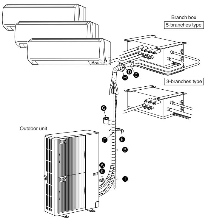
Fig. 2-1
- When installing the power lines, do not apply tension to the cables. If the connections are loosened, the cables can snap or break and overheating or fire may result.
- Be sure to ground the unit. Do not connect the ground wire to gas or water pipes, lighting rods, or telephone grounding lines. If the unit is not properly grounded, electric shock may result.
-
Use circuit breakers (ground fault interrupter, isolating switch (+B fuse), and molded case circuit breaker) with the specified capacity. If the circuit breaker capacity is larger than the specified capacity, breakdown or fire may result.
-
Do not touch any switch with wet hands. Electric shock may result.
- Do not touch the refrigerant pipes with bare hands during operation. The refrigerant pipes are hot or cold depending on the condition of the flowing refrigerant. If you touch the pipes, burns or frostbite may result.
-
After stopping operation, be sure to wait at least five minutes before turning off the main power switch. Otherwise, water leakage or breakdown may result.
-
Do not use refrigerant other than R410A refrigerant. If another refrigerant is used, the chlorine will cause the oil to deteriorate.
- Use the following tools specifically designed for use with R410A refrigerant. The following tools are necessary to use R410A refrigerant. Contact your nearest dealer for any questions.
| Tools (for R410A) |
| Gauge manifold | Flare tool |
| Charge hose | Size adjustment gauge |
| Gas leak detector | Vacuum pump adapter |
| Torque wrench | Electronic refrigerant charging scale |
- Be sure to use the correct tools. If dust, debris, or moisture enters the refrigerant lines, refrigeration oil deterioration may result.
- Do not use a charging cylinder. If a charging cylinder is used, the composition of the refrigerant will change and the efficiency will be lowered.
2.1. Before installation (Fig. 2-1)
This installation manual is only for the outdoor unit installation. In installing the indoor units and branch box, refer to the installation manual attached to each unit.
Any structural alterations necessary for the installation must comply with the local building code requirements.
This diagram is intended to show the configuration of accessories.
For actual installation, the outdoor unit is to be turned 180^
Units should be installed by licensed contractor according to local code requirement.
Note:
The dimensions given along the arrows above are required to guarantee the air conditioner's performance. Install the unit in as wide a place as possible for later service or repairs.
Parts to be locally procured
| A | Branch box/outdoor unit connecting wire
(3-core, Refer to 7.3. External wiring procedure) | 1 |
| B | Extension pipe | 1 |
| C | Wall hole sleeve | 1 |
| D | Wall hole cover | 1 |
| E | Pipe fixing band
(The quantity depends on the pipe length.) | 2 to 7 |
| F | Fixing screw for E 4 × 20 mm
(The quantity depends on the pipe length.) | 2 to 7 |
| G | Piping tape | 1 |
| H | Putty | 1 |
| I | Drain hose (hard PVC pipe VP16) | 1 |
| J | Refrigeration oil | 1 |
| K | Power supply cord
(2-core, Refer to 7.3. External wiring procedure) | 1 |
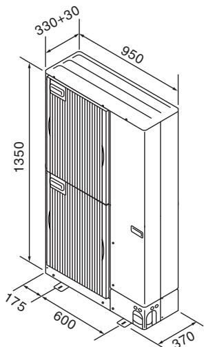
Fig. 3-1
(mm)
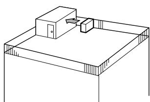
Fig. 3-2
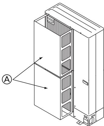
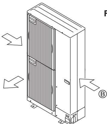
Fig. 3-3
Fig. 3-4
3.1. Refrigerant pipe
Refer to 5.2. Pipe length and height difference.
3.2. Choosing the outdoor unit installation location
- Avoid locations exposed to direct sunlight or other sources of heat.
- Select a location from which noise emitted by the unit will not inconvenience neighbors.
- Select a location permitting easy wiring and pipe access to the power source and indoor unit.
- Avoid locations where combustible gases may leak, be produced, flow, or accumulate.
- Note that water may drain from the unit during operation.
- Select a level location that can bear the weight and vibration of the unit.
- Avoid locations where the unit can be covered by snow. In areas where heavy snow fall is anticipated, special precautions such as raising the installation location or installing a hood on the air intake must be taken to prevent the snow from blocking the air intake or blowing directly against it. This can reduce the airflow and a malfunction may result.
- Avoid locations exposed to oil, steam, or sulfuric gas.
- Use the transportation handles of the outdoor unit to transport the unit. If the unit is carried from the bottom, hands or fingers may be pinched.
3.3. Outline dimensions (Outdoor unit) (Fig. 3-1)
Constraints on indoor unit installation
You should note that indoor units that can be connected to this outdoor unit are the following models.
- Indoor units with model numbers 22, 25, 35, 50, 60, 71, 80 can be connected. Refer to the table below for possible 2-8 room, indoor unit combinations.
Verification
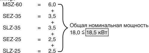
The rated capacity should be determined by observing the table below. The unit's quantities are limited in 2 to 8 units. For the next step, make sure that the total rated capacity selected will stay in a range of 4.4 - 18.5kW .
Example:
| MSZ-60 | = 6.0 |
| SEZ-35 | + 3.5 |
| SLZ-35 | + 3.5 |
| SEZ-25 | + 2.5 |
| SLZ-25 | + 2.5 |
| Indoor unit type | 22 | 25 | 35 | 50 | 60 | 71 | 80 |
| Rated capacity (Cooling) (kW) | 2.2 | 2.5 | 3.5 | 5.0 | 6.0 | 7.1 | 8.0 |
Combinations in which the total capacity of indoor units exceeds the capacity of the outdoor unit (=14.0kW) will reduce the cooling capacity of each indoor unit below their rated cooling capacity. Thus, combine indoor units with an outdoor unit within the outdoor unit's capacity (=14.0kW) , if possible.
3.4. Ventilation and service space
3.4.1. Windy location installation
When installing the outdoor unit on a rooftop or other location unprotected from the wind, situate the air outlet of the unit so that it is not directly exposed to strong winds. Strong wind entering the air outlet may impede the normal airflow and a malfunction may result.
The following shows three examples of precautions against strong winds.
① Face the air outlet towards the nearest available wall about 50~cm away from the wall. (Fig. 3-2)
② Install an optional air guide if the unit is installed in a location where strong winds from a typhoon, etc. may directly enter the air outlet. (Fig. 3-3)
Air guide
③ Position the unit so that the air outlet blows perpendicularly to the seasonal wind direction, if possible. (Fig. 3-4)
⑧ Wind direction
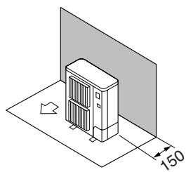
Fig. 3-5
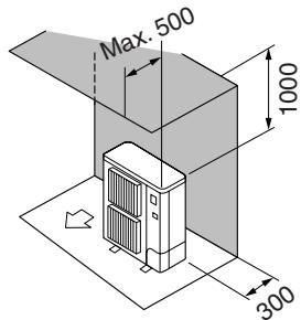
Fig. 3-6
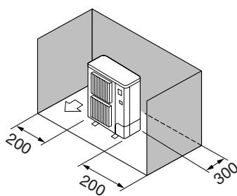
Fig. 3-7
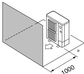
Fig. 3-8
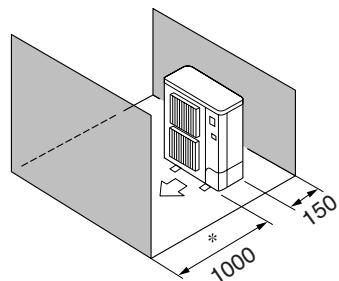
Fig. 3-9
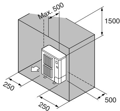
Fig. 3-10
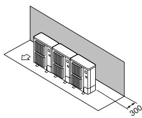
Fig. 3-11

Fig. 3-12
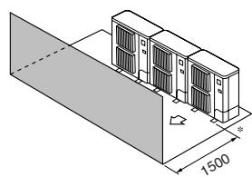
Fig. 3-13
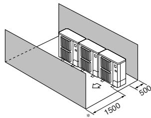
Fig. 3-14
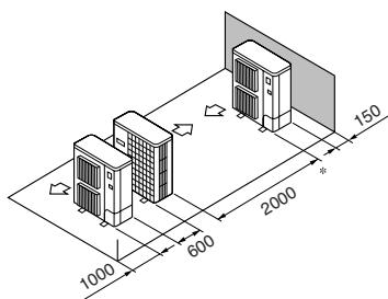
Fig. 3-15
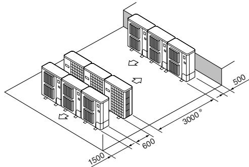
Fig. 3-16
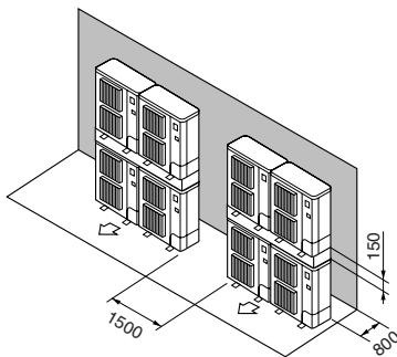
Fig. 3-17
3.4.2. When installing a single outdoor unit
Minimum dimensions are as follows, except for Max., meaning Maximum dimensions, indicated.
Refer to the figures for each case.
① Obstacles at rear only (Fig. 3-5)
② Obstacles at rear and above only (Fig. 3-6)
③ Obstacles at rear and sides only (Fig. 3-7)
④ Obstacles at front only (Fig. 3-8)
- When using an optional air outlet guide, the clearance is 500 mm or more.
⑤ Obstacles at front and rear only (Fig. 3-9)
* When using an optional air outlet guide, the clearance is 500 mm or more.
(6) Obstacles at rear, sides, and above only (Fig. 3-10)
- Do not install the optional air outlet guides for upward airflow.
3.4.3. When installing multiple outdoor units
Leave 10mm space or more between the units.
① Obstacles at rear only (Fig. 3-11)
② Obstacles at rear and above only (Fig. 3-12)
- No more than three units must be installed side by side. In addition, leave space as shown.
- Do not install the optional air outlet guides for upward airflow.
③ Obstacles at front only (Fig. 3-13)
- When using an optional air outlet guide, the clearance is 1000 mm or more.
④ Obstacles at front and rear only (Fig. 3-14)
- When using an optional air outlet guide, the clearance is 1000mm or more.
⑤ Single parallel unit arrangement (Fig. 3-15)
- When using an optional air outlet guide installed for upward airflow, the clearance is 1000 mm or more.
⑥ Multiple parallel unit arrangement (Fig. 3-16)
- When using an optional air outlet guide installed for upward airflow, the clearance is 1500 mm or more.
⑦ Stacked unit arrangement (Fig. 3-17)
- The units can be stacked up to two units high.
- No more than two stacked units must be installed side by side. In addition, leave space as shown.
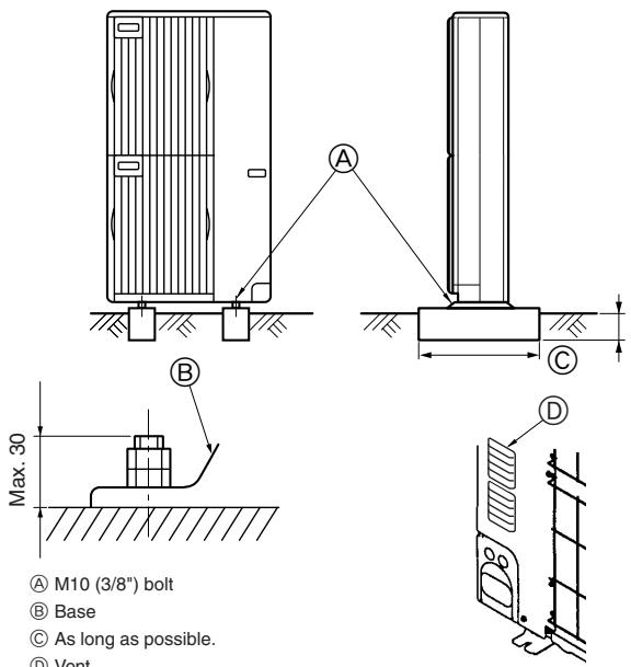
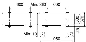
Fig. 4-1
- Be sure to install the unit in a sturdy, level surface to prevent rattling noises during operation. (Fig. 4-1)
| Foundation bolt | M10 (3/8") |
| Thickness of concrete | 120 mm |
| Length of bolt | 70 mm |
| Weight-bearing capacity | 320 kg |
- Make sure that the length of the foundation bolt is within 30~mm of the bottom surface of the base.
- Secure the base of the unit firmly with four-M10 foundation bolts in sturdy locations. Installing the outdoor unit
- Do not block the vent. If the vent is blocked, operation will be hindered and breakdown may result.
- In addition to the unit base, use the installation holes on the back of the unit to attach wires, etc., if necessary to install the unit. Use self-tapping screws ( 5 × 15 mm or less) and install on site.
Warning:
- The unit must be securely installed on a structure that can sustain its weight. If the unit is mounted on an unstable structure, it may fall down and cause damage or injuries.
- The unit must be installed according to the instructions in order to minimize the risk of damage from earthquakes, typhoons, or strong winds. An incorrectly installed unit may fall down and cause damage or injuries.
5. Installing the refrigerant piping
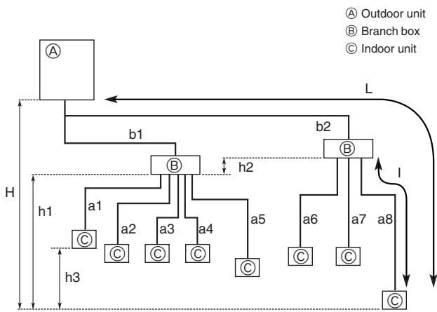
Fig. 5-1
5.1. Precautions for devices that use R410A refrigerant
- Refer to page 3 for precautions not included below on using air conditioners with R410A refrigerant.
- Use ester oil, ether oil, alkylbenzene oil (small amount) as the refrigeration oil applied to the flared sections.
- Use C1220 copper phosphorus, for copper and copper alloy seamless pipes, to connect the refrigerant pipes. Use refrigerant pipes with the thicknesses specified in the table to the below. Make sure the insides of the pipes are clean and do not contain any harmful contaminants such as sulfuric compounds, oxidants, debris, or dust.
Warning:
When installing or moving the air conditioner, use only the specified refrigerant (R410A) to charge the refrigerant lines. Do not mix it with any other refrigerant and do not allow air to remain in the lines. Air enclosed in the lines can cause pressure peaks resulting in a rupture and other hazards.
| ø6.35, ø9.52, ø12.7 | Thickness 0.8 mm |
| ø15.88 | Thickness 1.0 mm |
- Do not use pipes thinner than those specified above.
| Permissible length (one-way) | Total piping length | b1+b2+a1+a2+a3+a4+a5+a6+a7+a8 ≤ 115 m |
| Farthest piping length (L) | b2+a8 ≤ 70 m (b2 ≤ 55 m, a8 ≤ 15 m) |
| Piping length between outdoor unit and branch boxes | b1+b2 ≤ 55 m |
| Farthest piping length after branch box (l) | a8 ≤ 15 m |
| Total piping length between branch boxes and indoor units | a1+a2+a3+a4+a5+a6+a7+a8 ≤ 60 m |
| Permissible height difference (one-way) | In indoor/outdoor section (H)*1 | H ≤ 30 m (In case of outdoor unit is set higher than indoor unit) |
| H ≤ 20 m (In case of outdoor unit is set lower than indoor unit) |
| In branch box/indoor unit section (h1) | h1 + h2 ≤ 15 m |
| In each branch unit (h2) | h2 ≤ 15 m |
| In each indoor unit (h3) | h3 ≤ 12 m |
| Number of bends | | b1+a1 |, | b1+a2 |, | b1+a3 |, | b1+a4 |, | b1+a5 |, | b2+a6 |, | b2+a7 |, | b2+a8 | ≤ 15 |
*1 Branch box should be placed within the level between the outdoor unit and indoor units.
5.2. Pipe length and height difference (Fig. 5-1)
Flared connections
- This unit has flared connections on each indoor unit and branch box and outdoor unit sides.
- Remove the valve cover of the outdoor unit, then connect the pipe.
- Refrigerant pipes are used to connect the branch box and outdoor unit.
5.3. Addition of refrigerant
- Additional charging is not necessary for this unit if the total pipe length (b1+b2+a1+a2+a3+a4+a5+a6+a7+a8) does not exceed 40 m.
-
If the total pipe length exceeds 40m , charge the unit with additional R410A refrigerant according to the permitted pipe lengths in the chart below.
-
When the unit is stopped, charge the unit with the additional refrigerant through the liquid stop valve after the pipe extensions and indoor unit have been vacuumized.
When the unit is operating, add refrigerant to the gas check valve using a safety charger. Do not add liquid refrigerant directly to the check valve.
After charging the unit with refrigerant, note the added refrigerant amount on the service label (attached to the unit).
Refer to the "1.5. Using R410A refrigerant air conditioners" for more information.
Table 1
| Total piping length (b1+b2+a1+a2+a3+a4+a5+a6+a7+a8) | 41 - 50 m | 51 - 70 m | 71 - 90 m | 91 - 115 m |
| Additional refrigerant charging amount | 0.6 kg | 1.4 kg | 2.2 kg | 3.2 kg |
If connecting an indoor unit with 9.52 liquid pipes (model number 71 or more for M- and S-Series and model number 60 or more for P-Series), the additional refrigerant charging amount in Table 1 must be corrected (add the following R value from the value given in Table 1).
Additional refrigerant charging correction amount
R = 0.01[kg / m]× 9.52 branch pipe (liquid pipe) total length [m]
Example) b1 = 20 m , b2 = 25 m
| Indoor unit A | ø9.52 Liquid pipe | a1=12 m |
| Indoor unit B | ø6.35 Liquid pipe | a2=11 m |
| Indoor unit C | ø6.35 Liquid pipe | a6=14 m |
| Indoor unit D | ø9.52 Liquid pipe | a7=13 m |
Total piping length: b1+b2+a1+a2+a6+a7=95 m
According to Table 1, the additional refrigerant charging amount is 3.2kg
Because indoor units with 9.52 liquid pipes are connected (indoor units A and D in this example), the additional refrigerant charging amount must be corrected.
Additional refrigerant charging correction amount
R = 0.01[kg / m]× 9.52 branch pipe (liquid pipe) total length (a1+a7)
$$
\begin{array}{l} = 0. 0 1 \times (1 2 + 1 3 m) \ = 0. 2 5 \mathrm {k g} \ \end{array}
$$
Therefore, the additional refrigerant charging amount is 3.2kg + 0.25kg = 3.45kg .
In case of using 1-branch box
Flare connection employed. (No. brazing)
In case of using 2-branch boxes
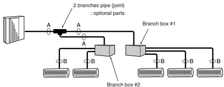
Fig. 5-2
(1) Valve size for outdoor unit
| For liquid | ø9.52 mm |
| For gas | ø15.88 mm |
(2)Valve size for branch box
| A UNIT | Liquid pipe | ø6.35 mm |
| Gas pipe | ø9.52 mm |
| B UNIT | Liquid pipe | ø6.35 mm |
| Gas pipe | ø9.52 mm |
| C UNIT | Liquid pipe | ø6.35 mm |
| Gas pipe | ø9.52 mm |
| D UNIT | Liquid pipe | ø6.35 mm |
| Gas pipe | ø9.52 mm |
| E UNIT | Liquid pipe | ø6.35 mm |
| Gas pipe | ø12.7 mm |
- 3-branch type: only A, B, C unit
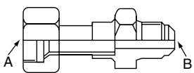
Fig. 5-3
| Conversion formula |
| 1/4 F | ø6.35 |
| 3/8 F | ø9.52 |
| 1/2 F | ø12.7 |
| 5/8 F | ø15.88 |
| 3/4 F | ø19.05 |
5.4. Selecting pipe size (Fig. 5-2)
| A | B |
| Liquid (mm) | ø9.52 | The piping connection size differs according to the type and capacity of indoor units. Match the piping connection size of branch box with indoor unit.
If the piping connection size of branch box does not match the piping connection size of indoor unit, use optional different-diameter (deformed) joints to the branch box side. (Connect deformed joint directly to the branch box side.) |
| Gas (mm) | ø15.88 |
Different-diameter joint (optional parts) (Fig. 5-3)
| Model name | Connected pipes diameter | Diameter A | Diameter B |
| mm | mm | mm |
| MAC-A454JP | ø9.52 →ø12.7 | ø9.52 | ø12.7 |
| MAC-A455JP | ø12.7 →ø9.52 | ø12.7 | ø9.52 |
| MAC-A456JP | ø12.7 →ø15.88 | ø12.7 | ø15.88 |
| PAC-493PI | ø6.35 →ø9.52 | ø6.35 | ø9.52 |
| PAC-SG76RJ-E | ø9.52 →ø15.88 | ø9.52 | ø15.88 |
Piping preparation
Table below shows the specifications of pipes commercially available.
| Outside diameter | Insulation thickness | Insulation material |
| mm | mm |
| 6.35 | 8 | Heat resisting foam plastic
0.045 specific gravity |
| 9.52 | 8 |
| 12.7 | 8 |
| 15.88 | 8 |
② Ensure that the 2 refrigerant pipes are insulated to prevent condensation.
③ Refrigerant pipe bending radius must be 100mm or more.

Caution:
Be sure to use the insulation of specified thickness. Excessive thickness may cause incorrect installation of the indoor unit and branch box, and lack of thickness may cause dew drippage.
2-branch pipe (Joint): Optional parts (According to the connection method, you can choose the favorite one.)
| Model name | Connection method |
| MSDD-50AR-E | flare |
| MSDD-50BR-E | brazing |
■ Installation procedure (2 branches pipe (Joint))
Refer to the installation manuals of MSDD-50AR-E and MSDD-50BR-E.

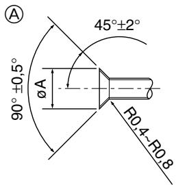
Flare cutting dimensions
Flare nut tightening torque
(B)
A (Fig. 5-4)
Fig. 5-4
| Copper pipe O.D. (mm) | Flare dimensionsøA dimensions (mm) |
| ø6.35 | 8.7 - 9.1 |
| ø9.52 | 12.8 - 13.2 |
| ø12.7 | 16.2 - 16.6 |
| ø15.88 | 19.3 - 19.7 |
(B) (Fig. 5-4)
| Copper pipe O.D. (mm) | Flare nut O.D. (mm) | Tightening torque (N·m)* |
| ø6.35 | 17 | 14 - 18 |
| ø6.35 | 22 | 34 - 42 |
| ø9.52 | 22 | 34 - 42 |
| ø9.52 | 26 | 49 - 61 |
| ø12.7 | 26 | 49 - 61 |
| ø12.7 | 29 | 68 - 82 |
| ø15.88 | 29 | 68 - 82 |
| ø15.88 | 36 | 100 - 120 |
*1 N·m ≈ 10 kgf·cm
Fig. 5-5
A Die
Copper pipe
Refrigerant collection when relocating the indoor and outdoor units (pump down)
① Connect a gauge manifold valve (pressure gauge included) to the service port near the gas stop valve of the outdoor unit so that the refrigerant pressure can be measured.
② Turn on the power supply (circuit breaker).
③ Close the liquid stop valve, and then perform the test run for cooling operation (SW4-1: ON and SW4-2: OFF).
- Be sure to wait at least 3 minutes after turning on the power supply before setting SW4-1 and SW4-2. If the DIP switches are set before 3 minutes has elapsed, the test run may not start.
④ Fully close the gas stop valve when the pressure reading on the gauge drops to 0.05 - 0.00MPa^* (approximately 0.5 - 0.0kgf/cm^2 ).
- If too much refrigerant has been added to the air conditioner system, the pressure may not drop to 0.5kgf/cm^2 . If this occurs, use a refrigerant collecting device to collect all of the refrigerant in the system, and then recharge the system with the correct amount of refrigerant after the indoor and outdoor units have been relocated.
⑤ Stop the air conditioner operation (SW4-1: OFF and SW4-2: OFF).
⑥ Turn off the power supply (circuit breaker).
5.5. Connecting pipes (Fig. 5-4)
- When commercially available copper pipes are used, wrap liquid and gas pipes with commercially available insulation materials (heat-resistant to 100^ or more, thickness of 12mm or more).
- The indoor parts of the drain pipe should be wrapped with polyethylene foam insulation materials (specific gravity of 0.03, thickness of 9 mm or more).
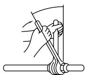
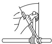
- Apply thin layer of refrigerant oil to pipe and joint seating surface before tightening flare nut. A
- Use two wrenches to tighten piping connections. (B)
- Use leak detector or soapy water to check for gas leaks after connections are completed.
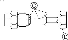
- Apply refrigerating machine oil over the entire flare seat surface. ©
- Use the flare nuts as follows. (D)
Pipe size (Outdoor unit-Branch box)
| Pipe size (ømm) | Liquid | ø9.52 |
| Gas | ø15.88 |
| The lineup of a connectable indoor unit depends on a district/areas/country. |
Pipe size (Branch box-Indoor unit) *Case of M series or S series Indoor unit
| Indoor unit type | (kW) | 22 | 25 | 35 | 50 | 60 | 71 | 80 |
| Pipe size (ømm) | Liquid | ø6.35 | ø6.35 | ø6.35 | ø6.35 | ø6.35 | ø9.52 | ø9.52 |
| Gas | ø9.52 | ø9.52 | ø9.52 | ø12.7 | ø15.88* | ø15.88 | ø15.88 |
- When using 60 type indoor unit of MEXZ series, use the flare nut in the indoor unit accessory for the gas side connecting of indoor unit.
Do not use the flare nut (gas side) attached to the indoor unit. If it is used, a gas leakage or even a pipe extraction may occur.
Pipe size (Branch box-Indoor unit) *Case of P series indoor unit
| Indoor unit type | (kW) | 35 | 50 | 60 | 71 |
| Pipe size (ømm) | Liquid | ø6.35 | ø6.35 | ø9.52 | ø9.52 |
| Gas | ø12.7 | ø12.7 | ø15.88 | ø15.88 |
When using 35, 50 type indoor unit of P series, use the flare nut attached to the indoor unit.
Do not use the flare nut (in the indoor unit accessory). If it is used, a gas leakage or even a pipe extraction may occur.
- When bending the pipes, be careful not to break them. Bend radii of 100mm to 150 mm are sufficient.
- Make sure the pipes do not contact the compressor. Abnormal noise or vibration may result.
① Pipes must be connected starting from the indoor unit. Flare nuts must be tightened with a torque wrench.
② Flare the liquid pipes and gas pipes and apply a thin layer of refrigeration oil (Applied on site).
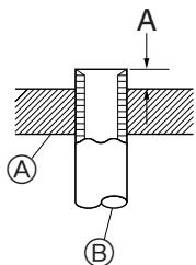
- When usual pipe sealing is used, refer to Table 2 for flaring of R410A refrigerant pipes.
The size adjustment gauge can be used to confirm A measurements.
Table 2 (Fig. 5-5)
| Copper pipe O.D. (mm) | A (mm) |
| Flare tool for R410A | Flare tool for R22-R407C |
| Clutch type |
| ø6.35 (1/4") | 0 - 0.5 | 1.0 - 1.5 |
| ø9.52 (3/8") | 0 - 0.5 | 1.0 - 1.5 |
| ø12.7 (1/2") | 0 - 0.5 | 1.0 - 1.5 |
| ø15.88 (5/8") | 0 - 0.5 | 1.0 - 1.5 |
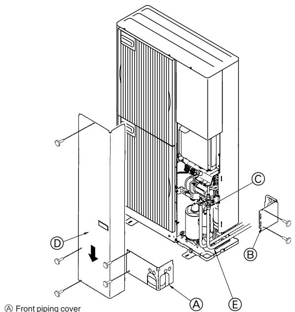
Front piping cover
⑧ Piping cover
Stop valve
Service panel
E Band radius : 100 mm - 150 mm
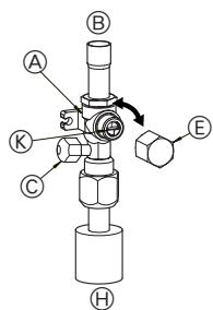
Fig. 5-6
(1)
(2)
Type A
Type B
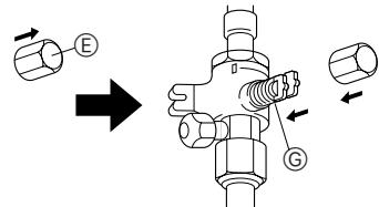
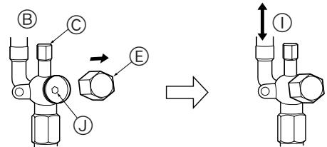
Fig. 5-7
(3)
H
Type C
Fig. 5-8
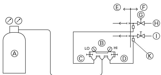
Fig. 5-9
5.6. Refrigerant piping (Fig. 5-6)
Remove the service panel (three screws) and the front piping cover (A) (two screws) and rear piping cover (B) (two screws). Refrigerant pipes are protectively wrapped
- The pipes can be protectively wrapped up to a diameter of 90 before or after connecting the pipes. Cut out the knockout in the pipe cover following the groove and wrap the pipes.
Pipe inlet gap
- Use putty or sealant to seal the pipe inlet around the pipes so that no gaps remain. (If the gaps are not closed, noise may be emitted or water and dust will enter the unit and breakdown may result.)
5.7. Caution for piping connection/valve operation
- Conduct piping connection and valve operation accurately by following the figure below.
- Apply sealer along the insulator to prevent water entering the insulator covering the refrigerant pipe joints.
- After evacuation and refrigerant charge, ensure that the handle is fully open. If operating with the valve closed, abnormal pressure will be imparted to the high- or low-pressure side of the refrigerant circuit, giving damage to the compressor, etc.
- Determine the amount of additional refrigerant charge (refer "5.3. Addition of refrigerant"), and charge refrigerant additionally through the service port after completing piping connection work.
- After completing work, tighten the service port (12 - 15 N·m) and cap (20 - 25 N·m) securely to prevent gas leak.
^*1 N·m 10 kgf·cm
Method of completely opening the stop valve
The stop valve opening method varies according to the outdoor unit model. Use the appropriate method to open the stop valves.
(1) Type A (Fig. 5-7)
① Remove the cap, then turn one-quarter rotation counter-clockwise with a flat-bladed screwdriver to complete open.
② Check that the valves are fully open, then return the cap to its original state and tighten it down.
(2) Type B (Fig. 5-7)
① Remove the cap, pull the handle toward you and rotate 1/4 turn in a counterclockwise direction to open.
② Make sure that the stop valve is open completely, push in the handle and rotate the cap back to its original position.
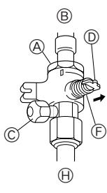
(3) Type C (Fig. 5-8)
① Remove the cap and turn the valve rod counterclockwise as far as it will go with the use of a 4 mm hexagonal wrench. Stop turning when it hits the stopper.
② Make sure that the stop valve is open completely and rotate the cap back to its original position.
A Valve
B Unit side
Service port
Handle
E Cap
Completely closed
Completely open
(On-side installation) Refrigerant piping side
① Direction the refrigerant flows in
① Wrench hole
Operation section
5.8. Airtight test and evacuation
① Airtight test (Fig. 5-9)
Airtight test should be made by pressurizing nitrogen gas. For the test method, refer to the following figure.
(1) Connecting the testing tool. Make a test with the stop valve closed. Be also sure to pressurize both liquid or high-pressure pipe and gas or low pressure pipe.
(2) Do not add pressure to the specified pressure all at once; add pressure little by little.
① Pressurize to 0.5MPa ( 5kgf/cm^2G ), wait five minutes, and make sure the pressure does not decrease.
(2) Pressurize to 1.5 MPa ( 15 ~kgf/cm^2 ~G ), wait five minutes, and make sure the pressure does not decrease.
③ Pressurize to 4.15MPa (41.5kgf/cm^2G) and measure the surrounding temperature and refrigerant pressure.
(3) If the specified pressure holds for about one day and does not decrease, the pipes have passed the test and there are no leaks.
- If the surrounding temperature changes by 1^ , the pressure will change by about 0.01MPa ( 0.1kgf/cm^2G ). Make the necessary corrections.
(4) If the pressure decreases in steps (2) or (3), there is a gas leak. Look for the source of the gas leak.
Nitrogen gas
Outdoor unit
System analyzer
Stop valve
Lo-knob
Liquid pipe or high-pressure pipe
@ Hi-knob
① Gas pipe or low-pressure pipe
To branch box
Service port
Freon cylinder
⑧ Scale
Valve
⑥ 3-way joint
Vacuum pump
F System analyzer
⑥ Lo-knob
Hi-knob
① To branch box
① Outdoor unit
Stop valve
Liquid pipe or high-pressure pipe
Gas pipe or low-pressure pipe
Service port
Fig. 5-10
Fig. 5-11
The figure to the left is an example only. The stop valve shape, service port position, etc., may vary according to the model.
Turn section A only.
(Do not further tighten sections A and B together.)
Charge hose
Service port
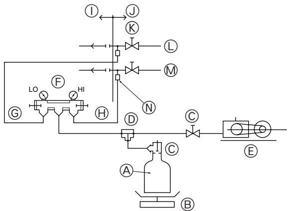
② Evacuation (Fig. 5-10)
Evacuation should be made from the service port provided on the outdoor unit's stop valve to the vacuum pump commonly used for both liquid or high-pressure pipe and gas or low-pressure pipe. (Make evacuation from both liquid or high-pressure pipe and gas or low-pressure pipe with the stop valve closed.)
Remember: Never carry out air purge by refrigerant.
Warning:
When installing or moving a unit to another place, do not mix anything other than specified refrigerant into the refrigeration cycle. If air is mixed, the refrigeration cycle may obtain abnormally high pressure, resulting in a burst pipe.
- A high-precision gravimeter measurable up to 0.1kg should be used. If you are unable to prepare such a high-precision gravimeter, you may use a charging cylinder.
Note:
- Use a gauge manifold, changing hose, and other parts for the refrigerant indicated on the unit.
- Use a gravimeter. (One that can measure down to 0.1kg )
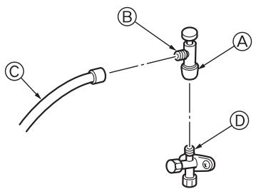
Precautions when using the charge valve (Fig.5-11)
Do not tighten the service port too much when installing it, otherwise, the valve core could be deformed and become loose, causing a gas leak.
After positioning section in the desired direction, turn section only and tighten it. Do not further tighten sections and together after tightening section .
6. Drainage piping work
Outdoor unit drainage pipe connection
When drain piping is necessary, use the drain socket or the drain pan (option).
| Drain socket | PAC-SG61DS-E |
| Drain pan | PAC-SG64DP-E |
7. Electrical work
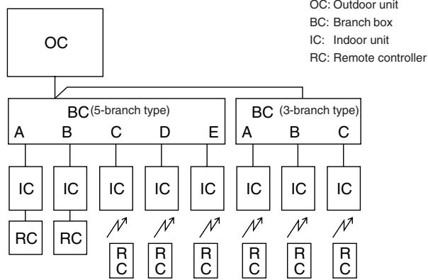
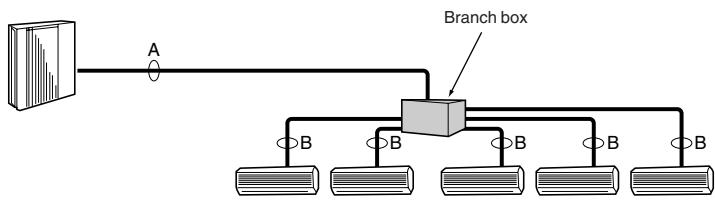
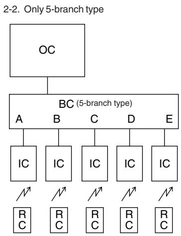
[1] Basic systems

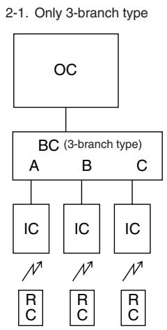
[2] Standard systems
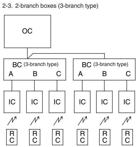
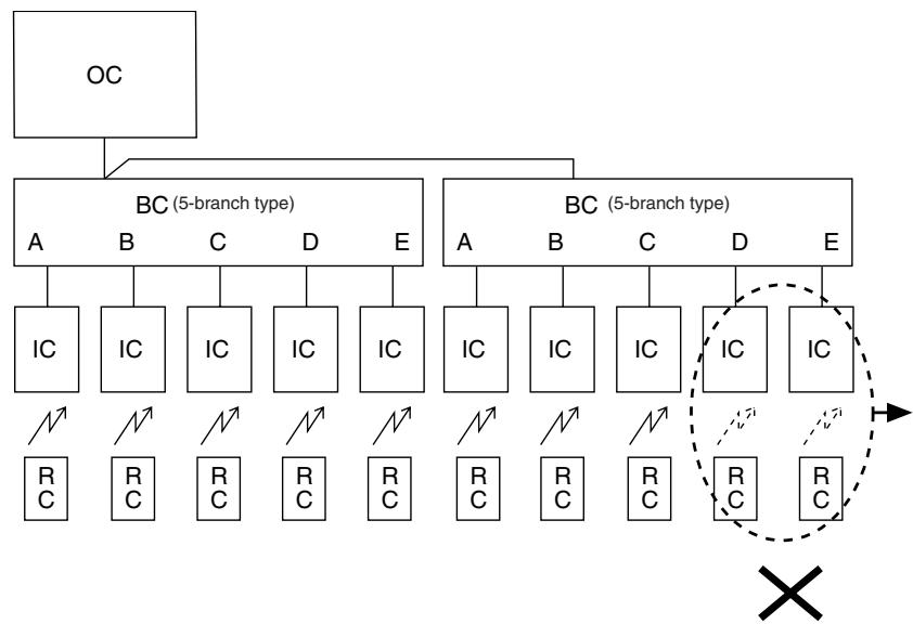
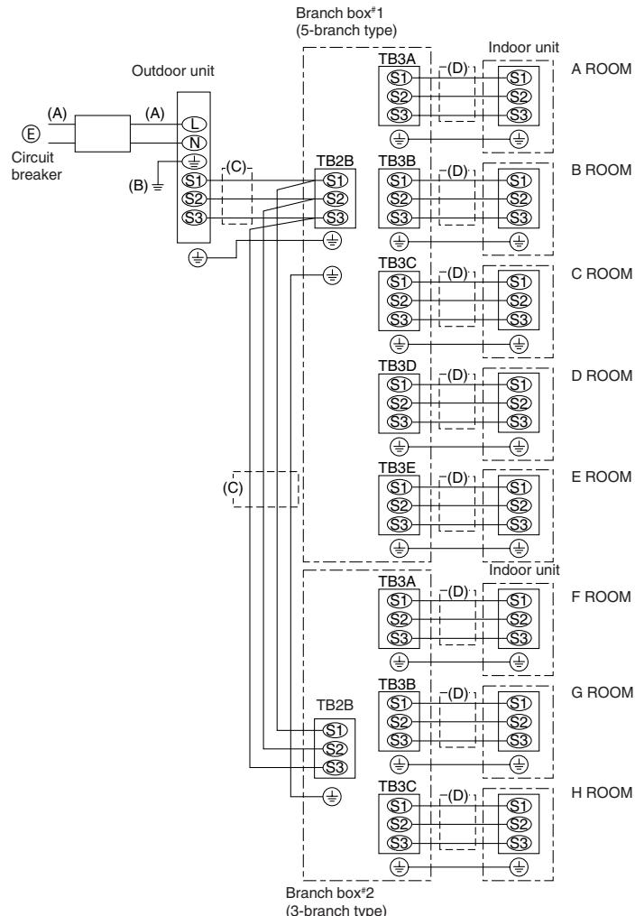
2-4. 2 branch boxes (5-branch type, maximum 8 indoor units)
- Up to 2 branch boxes can be connected to a single outdoor unit.
- Up to 8 indoor units can be connected to the system.
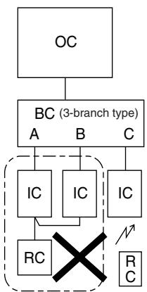
[3] Incorrect systems
3-1. Group operation by single remote controller
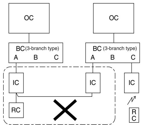
3-2. Group operation between different refrigerant systems
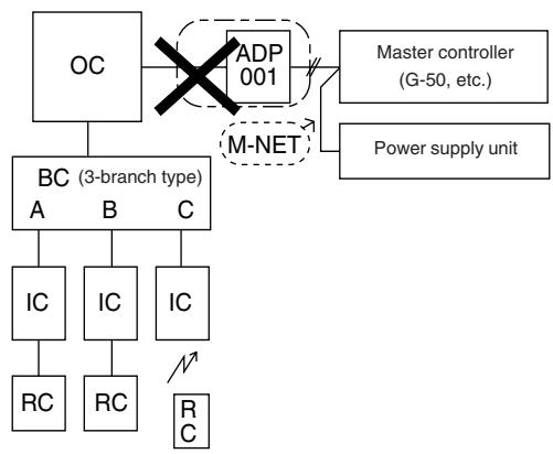
3-3. Connection of M-NET adapter to outdoor unit
3-1. Plural indoor units cannot be operated by a single remote controller.
3-2. Different refrigerant systems cannot be connected together.
3-3. A M-NET adapter cannot be connected to an outdoor unit.
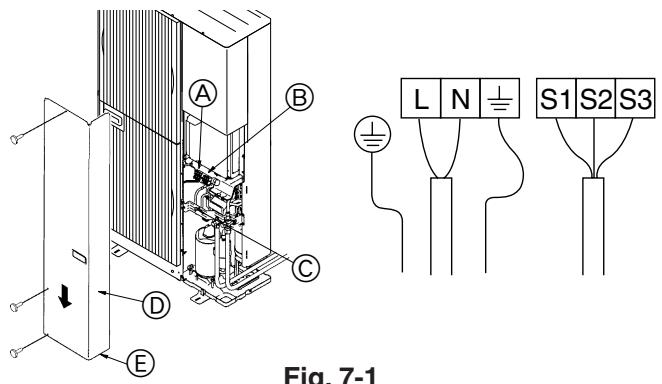
Fig. 7-1
7.1. Outdoor unit (Fig. 7-1)
① Remove the service panel.
② Wire the cables referring to the Fig. 7-1.
Earth terminal
電 Terminal block
Clamp
Service panel
E Wire the cables so that they do not contact the center of the service panel or the gas valve.
7.2. Branch box/outdoor wire connection and outdoor power supply cord connection
Warning:
- Be sure to attach the terminal block covers/panel of the outdoor unit securely. If it is not attached correctly, it could result in a fire or an electric shock due to dust, water, etc.
- Be sure to connect the power supply cords and the connecting wires for the indoor units, outdoor units, and branch boxes directly to the units (no intermediate connections).
Intermediate connections can lead to communication errors if water enters the cords or wires and causes insufficient insulation to ground or a poor electrical contact at the intermediate connection point.
(If an intermediate connection is necessary, be sure to take measures to prevent water from entering the cords and wires.)

Caution:
- Be careful not to make mis-wiring.
- Firmly tighten the terminal screws to prevent them from loosening.
After tightening, pull the wires lightly to confirm that they not move.
- If the connecting wire is incorrectly connected to the terminal block, the unit does not operate normally.
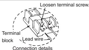
- Connect wire from the branch box correctly to the terminal block.
- For future servicing, give extra length to connecting wire.
(In case of 2-branch boxes)
Fig. 7-2
7.3. External wiring procedure (Fig. 7-2)
The power supply work is needed only to the outdoor unit. The power supply to the branch box or indoor unit is conducted through wiring.
Therefore, the power supply work can be carried out at just one spot of the outdoor unit. It will contribute to simplify the work and save costs.
E Power supply
single phase AC220/230/240 V, 50 Hz
AC220V,60Hz
Max. Permissive System Impedance 0.22(Ω)
Note:
① Power supply input: Outdoor unit only.
Connect the lines (C), (D) in accordance with the terminal block names to ensure correct polarity.
| Wire diameter | Breaker *1 |
| (A) Main power line | (B) Earth line | (C) Signal line | (D) Signal line | Interrupting current | Performance characteristic |
| 6.0 mm² | 6.0 mm² | 1.5 mm²*2 | 1.5 mm² | 40 A | 40A, 30 mA for 0.1 sec. or less |
When using twisted wire for the wiring, the use of round terminal is required.
1. A breaker with at least 3 mm contact separation in each pole shall be provided. Use non-fuse breaker (NF) or earth leakage breaker (NV).
2. Max. 45 m ("Outdoor unit - Branch box #1" plus "Branch box #1 - Branch box #2").
If 2.5mm^2 used, Max. 55 m.
Notes: 1. Wiring size must comply with the applicable local and national code.
2. Power supply cords and Indoor unit/branch box/outdoor unit connecting cords shall not be lighter than polychloroprene sheathed flexible cord. (Design 60245 IEC 57)
3. Install an earth line longer than power cables.
IMPORTANT
Make sure that the current leakage breaker is one compatible with higher harmonics.
Always use a current leakage breaker that is compatible with higher harmonics as this unit is equipped with an inverter.
The use of an inadequate breaker can cause the incorrect operation of inverter.
Warning:
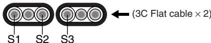
In case of A-control wiring, there is high voltage potential on the S3 terminal caused by electrical circuit design that has no electrical insulation between power line and communication signal line. Therefore, please turn off the main power supply when servicing. And do not touch the S1, S2, S3 terminals when the power is energized. If isolator should be used between outdoor unit and branch box/indoor unit and branch box, please use 3-poles type.
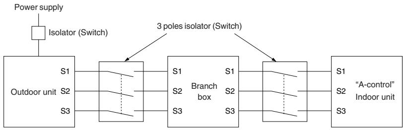
Caution:
After using the isolator, be sure to turn off and on the main power supply to reset the system. Otherwise, the outdoor unit may not be able to detect the branch box(es) or indoor units.
WIRING SPECIFICATIONS
(OUTDOOR-BRANCH BOX CONNECTING CABLE)
| Cross section of cable | Wire size (mm2) | Number of wires | Polarity | L (m)*6 |
| Round | 2.5 | 3 | Clockwise: S1-S2-S3* Pay attention to stripe of yellow and green | (50)*2 |
| Flat | 2.5 | 3 | Not applicable(Because center wire has no cover finish) | Not applicable*5 |
| Flat | 1.5 | 4 | From left to right: S1-Open-S2-S3 | (45)*3 |
| Round | 2.5 | 4 | Clockwise: S1-S2-S3-Open*Connect S1 and S3 to the opposite angle | (55)*4 |
1 : Power supply cords of appliances shall not be lighter than design 60245 IEC or 227 IEC.
2 : In case that cable with stripe of yellow and green is available.
3 : In case of regular polarity connection (S1-S2-S3), wire size is 1.5 mm^2 .
4 : In case of regular polarity connection (S1-S2-S3).
*5 : In the flat cables are connected as this picture, they can be used up to 55 m.
*6 : Mentioned cable length is just a reference value.
It may be different depending on the condition of installation, Humidity or materials, etc.
Be sure to connect the outdoor-branch box/indoor-branch box connecting cables directly to the units (no intermediate connections).
Intermediate connections can lead to communication errors if water enters the cables and causes insufficient insulation to ground or a poor electrical contact at the intermediate connection point.
(If an intermediate connection is necessary, be sure to take measures to prevent water from entering the cables.)
8.1. Before test run
After completing installation and the wiring and piping of the indoor and outdoor units, check for refrigerant leakage, looseness in the power supply or control wiring, wrong polarity, and no disconnection of one phase in the supply.
- Use a 500-volt M-ohm tester to check that the resistance between the power supply terminals and ground is at least 1M
Do not carry out this test on the control wiring (low voltage circuit) terminals.
Warning:
Do not use the air conditioner if the insulation resistance is less than 1 MΩ.
Insulation resistance
After installation or after the power source to the unit has been cut for an extended period, the insulation resistance will drop below 1M due to refrigerant accumulating in the compressor. This is not a malfunction. Perform the following procedures.
- Remove the wires from the compressor and measure the insulation resistance of the compressor.
-
If the insulation resistance is below 1M , the compressor is faulty or the resistance dropped due to the accumulation of refrigerant in the compressor.
-
After connecting the wires to the compressor, the compressor will start to warm up after power is supplied. After supplying power for the times indicated below, measure the insulation resistance again.
- The insulation resistance drops due to accumulation of refrigerant in the compressor. The resistance will rise above 1M after the compressor is warmed up for two to three hours.
(The time necessary to warm up the compressor varies according to atmospheric conditions and refrigerant accumulation.)
- To operate the compressor with refrigerant accumulated in the compressor, the compressor must be warmed up at least 12 hours to prevent breakdown.
- If the insulation resistance rises above 1M , the compressor is not faulty.
Caution:
- The compressor will not operate unless the power supply phase connection is correct.
- Turn on the power at least 12 hours before starting operation.
- Starting operation immediately after turning on the main power switch can result in severe damage to internal parts. Keep the power switch turned on during the operational season.
The followings must be checked as well.
- The outdoor unit is not faulty. LED on the control board of the outdoor unit flash when the outdoor unit is faulty.
- Both the gas and liquid stop valves are completely open.
8.2. Test run
8.2.1. Using remote controller
Refer to the indoor unit installation manual.
- Be sure to perform the test run for each indoor unit. Make sure each indoor unit operates properly following the installation manual attached to the unit.
- If you perform the test run for all indoor units at once, you cannot detect any erroneous connection, if any, of the refrigerant pipes and the connecting wires.
- The compressor operation is not available for 3 minutes at least after the power is supplied.
- The compressor can emit noise just after turn on the power supply or in case of low outside air temperature.
About the restart protective mechanism
Once the compressor stops, the restart preventive device operates so the compressor will not operate for 3 minutes to protect the air conditioner.
8.2.2. Using SW4 in outdoor unit
In case of the test run from outdoor unit, all indoor units operate. Therefore, you can not detect any erroneous connection of refrigerant pipes and the connecting wires. If it aims at detection of any erroneous connection, be sure to carry out the test run from remote controller with reference to "8.2.1. Using remote controller."
| SW4-1 | ON | Cooling operation |
| SW4-2 | OFF |
| SW4-1 | ON | Heating operation |
| SW4-2 | ON |
- After performing the test run, set SW4-1 to OFF.
- A few seconds after the compressor starts, a clanging noise may be heard from the inside of the outdoor unit. The noise is coming from the check valve due to the small difference in pressure in the pipes. The unit is not faulty.
The test run operation mode cannot be changed by DIP switch SW4-2 during the test run. (To change the test run operation mode during the test run, stop the test run by DIP switch SW4-1. After changing the test run operation mode, resume the test run by switch SW4-1.)
When a test run is started by "Using SW4 in outdoor unit", even if it carries out stop instructions by remote controller, outdoor unit does not stop (a test run is not ended). In this case, please set SW4 in outdoor unit to off.
Note:
Be sure to wait at least 3 minutes after turning on the power supply before setting SW4-1 and SW4-2. If the DIP switches are set before 3 minutes has elapsed, the test run may not start.

Remote control panel
⑧ Relay circuit
External input adapter (PAC-SC36NA)
Outdoor unit control board
Relay power supply
Procure locally
Max. 10m
Orange
① Brown
① Red
Fig. 9-1
Remote control panel
⑧ Relay circuit
External input adapter (PAC-SC36NA)
Outdoor unit control board
Relay power supply
Procure locally
G Max. 10 ~m
Orange
① E
Red
Fig. 9-2
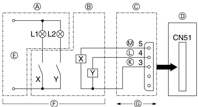
L1: Error display lamp
L2: Compressor operation lamp
X, Y: Relay (Coil standard of 0.9W or less for DC 12V)
X,Y:Relay (DC1mA)
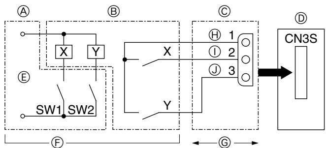
Fig. 9-3
Fig. 9-4
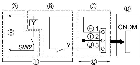
9.1. Low noise mode (on-site modification) (Fig. 9-1)
By performing the following modification, operation noise of the outdoor unit can be reduced by about 3-4 dB.
The low noise mode will be activated when a commercially available timer or the contact input of an ON/OFF switch is added to the CNDM connector (option) on the control board of the outdoor unit.
- The capacity may be insufficient according to the outdoor temperature and conditions, etc.
① Complete the circuit as shown when using the external input adapter (PACS36NA). (Option)
9.2. Demand function (on-site modification) (Fig. 9-2)
- It is possible to reduce electricity consumption within a range from 0 to 100 percent by performing the following on-site installation.
The demand function can be enabled by adding a commercially available input contact point ON/OFF switch to the CNDM connector (the contact point demand input, sold separately).
① Incorporate the "Adaptor for external input (PAC-SC36NA)" into the circuit as shown in the diagram on the left.
② By switching SW7-1 on the control circuit board for the outdoor unit, the following power consumption restrictions (compared to rated power) can be set.
| SW7-1 | Power consumption when SW2 is on |
| OFF | 0% (Forced compressor stop) |
| ON | 50% |
9.3. Error and compressor operation monitoring function (CN51)
Remote control panel
⑧ Relay circuit
External output adapter (PAC-SA88HA-E)
Outdoor unit control board
Lamp power supply
Procure locally
Max. 10m
Orange
Yellow
M Green
9.4. Auto change over - Operation mode locking function by external signal (CN3S)
Remote control panel
⑧ Relay circuit
External input adapter (PAC-SC36NA)
Outdoor unit control board
Relay power supply
Procure locally
Max.10m
Orange
① Brown
Red
| ON | OFF |
| SW1 | Heating | Cooling |
| SW2 | Validity of SW1 | Invalidity of SW1 |
- Any indoor unit that is operating in a mode different from the one specified by the external signal will enter the standby mode.
- The setting becomes effective when the outdoor unit is under stop.
-
The operation mode specified for the test run has priority over the mode specified using this function.
-
Sicherheitsvorkehrungen 16
- Installationszeichnung und Teile 17
- Aufstellort 18
- Einbau der Außenanlage 20
-
Installation der Kätemittelrohrleitung 20
-
Verrohrung der Dranage 24
- Elektroarbeiten 24
8.Testlauf 28
- Spezielle Funktionen 29
[2] Systemes standard
⑥ Circuitoduysunctor
① Marrón
Adaptador de salute externo (PAC-SC36NA)
① Rojo
Cuadro de control de la unida
ApaieoTe To kanaki (tpeic biEc), to eunpooio A kalumu ta twv oawnywoewv (duo biEc) kai to niow kalumu ta twv owlambdaovewv (duo biEc).
Oi oWAnvEc yukTKoU tuIiyovTal npooekTka e Taivia yia npootaia
OlaanvocuupovvaTuixouvuePooateuteukTiaivayoxoV daetpo 90 npiv n eTa m ouveon Touc.AvoTe m xapayevn Tpua Oto kalumaowavonovakolouovotacmuaakowkau taiuTce touc anyene.
Avoiya eiooou olambda
XpnouonnoTe oToK novotko uIko yia va appayiaTe to omueio ouvdeoc Tsw OwIyvw wTe va mny unapxouv keva.
(Av ta keva oppayiou, mopoie va akoyetai aouvnthetaoc, opuoic na 1oxwpoeoi mtmovadaokovn vepo kai va npokaolei .
5.7. Ppoooxynia tn ouvdoan twv oawnvwoeov/tn Aetoupyia nS 6a6iida
- Ipaayatonoiote owa ta ouvdeoeic twv ownywewkai n aeitoupyia nC baBidae me n Bontheia twv ekovwv.
- Epapuote OTEyawwTko Uliko kata mKoc Tou mvwtkou aywyou wTe va mnu naive vpo oToV aywyO nnepiBaaIc TswovnWvseWv uKTko.
- Meta tv EApwn kai tv npwn me yukto, beaowite ot n baiaidea evai eveaw avokn. Av npovda teei oe leoupyia me tn baiia kxaotn, Ta avantuxe i quaoioyik nioc tn neuupa uynnc h xanunc tiene tsou kukawatocpsienc npokalwvtacbaan oto uunne tkt.
Ipo0tiy TIOOHTaTOU UKtIKOU TOA BA uAnpOwEt (AVATSETe AMV VOTMa "5.3. PooHnKu YKTIKOU) K aunPnPoTe UKtIKoEeW GupDac auYpnnc apou OakLnPoeTe Tc auVbEsGcTow AwNvwoew.
- Otav teλeioεTe, σiEτ καλa Tn θuρiδa ouvtηροης (12 - 15 N·m) kal to kana(20 - 25 N·m) ia va atopéuxθei n diappoia aepiou.
- 1 N·m ≈ 10 kgf·cm
(3) C-type (Fig. 5-8)
KABLO BAGLANTISI TEKNIK ÖZELLIKLERI
(DIS UNITE-SUBE KUTUSU BAGLANTI KABLOSU)
JIO6bIe KOHCTpyKUOHHbIe N3MeHeHnE, Heo6XoIMMbIe IJIa MOHTaJa, OJINxHbI OTBeaTb Tpe6OBAHNM MeCTbIX NoCTaHOBHeN B CTPOITeHbONcpepe.
3a xcema npednHa3HauHena dIy IINIOCTpaum KOHNpyraum npHAnJNEXHOCTe.
Iy oOcctBtneHnI paKTmecKO MOHTaKa, HApKHBn pNbOp Heo6xOIM NOBepHyb Ha 180°.
PpIbOpdoJxHcTahABnBAtbNoDpaDnK,ImeOuCneuaNbHOe pa3peWeHne, cornacho Tpe6oBaHNMeCTbIX NoCTaHOBJIeHNI.
PpmeaHne:
Pa3Mepbl, npBBeHbIe OKoNo CTpeNok BblIe, Heo6xOdMbI dJIro o6ecneHnnaPon3BOAnTeJbHOCTN KOHdUcHHepa. YctahabnBaIte np6Op B HAn6BoeeuHPOKOM MeTe, HAcKOBbKO 3To BO3MOXHO, dJI NOcLJeUoJero O6cLyXHBaHHNJPEMOHaT.
DeTALn, noLexkaunc caMOCToTeJbHOMy npno6peTeHHIO
OrpaHnueHn no MoHTaxy BHyTpHeHero np60pa
Bam Heo6bOIMnOB6pATNTB BHMNHAMe HAO TTO K DaHOMHYaPauKxHOMY PnIbOpy MOXHO NQkLNQHTB BHTyPteHNHEPiNp6Opbl CneDyIOUxM OMOJeH.
- MoXHo NOJDKIIOUaTb BNYTpEHHne PnI6OpbIc HOMepAMn MOJeNei 22, 25, 35, 50, 60, 71, 80. B Ta6JIne HIXe PnIBOaTcB O3MOxHbIe KOM6INHauIN BNYTpEHHN x PnI6OpOB no CXME 2 - 8 B NOMEUeHHN.
Поберка
HOMINAHBHyo MOUHOCTb CnEDyET ONpeDEnITb C yHTOem TabNtBu HIXe. KOINHECTBO npbnopobor orpahnHeNo HCnOM OT 2 do 8. Ha cneIyoem 3tane, y6beNTceB, YTO 06baa Bb6panhaHOMINAHBNa MOUHOCTb 6bEt HaxoDntCB b P nepeAn4.4-18.5 KBT.
Празмер:
- He ncpnoIb3yIte Tpy6bl 60nee ToHKnE, yem yka3aHo Bblie.
■PpoeDypa MOHTaxa (Tpy6a c 2 OTBtBHeHnMn (CTbIK)
Cm. RykoBoDcTbA no MoHTaXy MSDD-50AR-E n MSDD-50BR-E.
B
A PaCTpy6HbI CTbIK -pa3Mepbl
⑥ MoMeHT 3aTAXKn rAaKn paCTpy6HOrO CTbIka
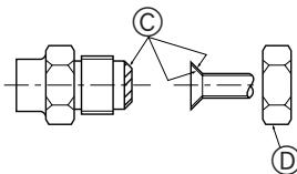
Fig. 5-4
A Fig.5-4
PnncnoIb3OBAHmB HHTpeHHHX Pnp6OpOB TINOB 35, 50 cepn P, nCnoIb3yIte KOhycHyraKy, npnilaraemyK BHTpeHHEmpy.
He nCnOJIb3yIte KOHycHyo rauKy (n3 KOMNJIeKTA pnpHaJNeXHoCTeK K BHTpHENMe np6Opy).EcII Na OHcNOnIb3yeTcH, MoXET BO3NHKnHYb yTeUka rAa 3n Ia daxe 3KCTpAkunr Tpy6bl.
-ПиИЗrIБeТуБ6БyIbTeOCTOPOKHbI,ЧTOБI HeДОПУСТИВx ПОПOMК. PeKOMeHdyOTcRaDnycbI ИЗrIb6a O T 100 MMdo 150 MM.
YOCTOBETBcT, CTO TpybIe bO nCnPKACAOTc C KOMPpeccopom. TaKoe cONPKOCBOHMe MOKet Bb3bIBAT NmHN Wym INN Bn6paUHO.
① CoeHHeHHe Tpy6 npOn3BODnTbC, NaHnHaO TBHyTpEnHero npIn60pa.
XomTybHa MyTax CneDyET 3aTnBAbTc NOMOuKIO KIOUc peRyIpyEmbIM ycIINEM.
② YctAHOBITE TpybI IaI XIAKOKTNI INI JRA3a I HAHECITNE TOHKMI CNOI MACNA OXJAXDEHIN (HAOTCBETCTBIOUCE MECTO).
B Cnlyae NcONb3ObaHnOB6bUHOrONoTHeHNr Tpy6bl, 6oPbATNTecb K Ta6bnue 2 dJe cnpabKn O coeINHmNrTpy6 dl xnaLadareHTa R410A.
9.2.需求功能(现场修改)(Fig.9-2)
Note: This symbol mark is for EU countries only.
This symbol mark is according to the directive 2002/96/EC
Article 10 Information for users and Annex IV.
English
Your MITSUBISHI ELECTRIC product is designed and manufactured with high quality materials and components which can be recycled and reused.
This symbol means that electrical and electronic equipment, at their end-of-life, should be disposed of separately from your household waste.
Please, dispose of this equipment at your local community waste collection/recycling centre.
In the European Union there are separate collection systems for used electrical and electronic product.
Please, help us to conserve the environment we live in!
Deutsch
Note: This symbol mark is for EU countries only.
This symbol mark is according to the directive 2002/96/EC
Article 10 Information for users and Annex IV.
EaIyiká
To npoiov MITSUBISHI ELECTRIC nou i eivai oεδiaoévo kai kataokεuaoεvo ano uλika kal εξapntμata uynlnc noiotntac, ta onoia μnpouv va avakukλωθouv kai va xρησιοποηθouv ξavá.
To auto oto onmaivei ot nEeKtpoayikoc kai nEeKtpiokc Eoaniooc, oTo teLoC Tc diapkeia c zwoC tou, tha npéπει va anoppiptei exwpiotá ano ta unoloina okiak a onoppmuata oc.
This product is designed and intended for use in the residential, commercial and light-industrial environment.
The product at hand is based on the following EU regulations:
- Low Voltage Directive 2006/95/ EC
- Electromagnetic Compatibility Directive 89/336/ EEC
Please be sure to put the contact address/telephone number on this manual before handing it to the customer.