
BioTec ScreenMatic 60000 - Water filter OASE - Free user manual and instructions
Find the device manual for free BioTec ScreenMatic 60000 OASE in PDF.

| Product type | Pond water filter |
| Brand | Oase |
| Model | BioTec ScreenMatic 60000 |
| Dimensions (L x W x H) | 788 x 590 x 554 mm |
| Weight (without water) | 25 kg |
| Power supply | 230 V / 50 Hz via 12 V DC transformer |
| Power consumption (control unit) | 5 W |
| Max water volume (without fish) | 60 m³ |
| Max water volume (with fish) | 30 m³ |
| Max water volume (with koi) | 15 m³ |
| Recirculation flow rate | 6000 to 11000 l/h |
| Inlet connections | 2 inlets, diameter 25/32/38 mm (G1, G1 1/4, G1 1/2) |
| Outlet connection | 1 outlet DN 75 |
| Impurities outlet connection | DN 50 |
| Permissible water temperature | +4 to +35 °C |
| Functions | Mechanical and biological filtration with automatic ScreenMatic pre-filter |
| Automatic cleaning | Yes, by motorized ScreenMatic screen |
| Manual cleaning | Yes, via button on the control unit |
| Filter foams | 2 blue, 3 red, 3 purple (8 units) |
| Special filter granules | 3.5 kg |
| Substrate tubes | 3 units (zeolite) |
| UVC clarifier connection | Yes, for Vitronic 18W/24W/36W, Bitron C and Bitron Eco |
| Electrical protection | Residual current device (RCD) 30 mA max |
| Wear parts | Filter foams, substrate tube, ScreenMatic screen |
Frequently Asked Questions - BioTec ScreenMatic 60000 OASE
User questions about BioTec ScreenMatic 60000 OASE
0 question about this device. Answer the ones you know or ask your own.
Ask a new question about this device
Download the instructions for your Water filter in PDF format for free! Find your manual BioTec ScreenMatic 60000 - OASE and take your electronic device back in hand. On this page are published all the documents necessary for the use of your device. BioTec ScreenMatic 60000 by OASE.
USER MANUAL BioTec ScreenMatic 60000 OASE
natural_image
Four black industrial storage units with blue trim, arranged in descending order (no visible text or symbols)BioTec ScreenMatic ^2
40000, 60000, 90000, 145000
EN Operating instructions
FR Notice d'emploi
BTC0050
BTC0077
BTC0049
BTC0056
natural_image
Isometric technical drawing of a rectangular electronic component with mounting holes and a central base (no text or symbols)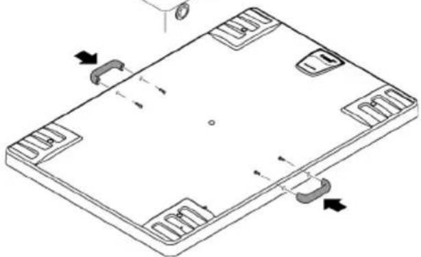
natural_image
Isometric technical diagram of a rectangular electronic component with mounting holes and internal slots, showing no text or symbols.BTC0051
natural_image
Technical line drawing of an electronic device chassis with internal components and mounting holes (no text or symbols)

BTC0052
WARNING
BTC0061
natural_image
Technical line drawing of an electronic device casing with internal components and mounting holes (no text or symbols)
bar
| Category | Percentage (%) | | :--- | :--- | | Top Bar | 100 | | Bottom Bar | 50 | | Right Arrow | ↑ ≈ | | Step | Description | | :--- | Description | | 1 | Top Bar (approx. 25%) | | 2 | Top Bar (approx. 75%) | | 3 | Bottom Bar (approx. 100%) |BTC0082
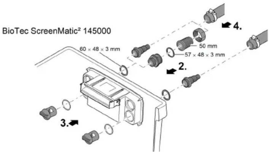
BioTec ScreenMatic ^2 145000
So gehen Sie vor:
BTC0055
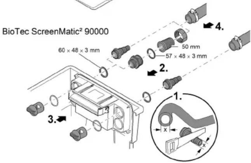
BioTec ScreenMatic ^2 90000
So gehen Sie vor:
BTC008
BioTec ScreenMatic ^2 145000
DE
So gehen Sie vor:
BTC008C
natural_image
Technical line drawing of an electronic device casing with internal components and directional arrows indicating movement (no text or symbols)BioTec ScreenMatic ^2 40000, 60000, 90000
BioTec ScreenMatic ^2 145000


natural_image
Technical diagram of a mechanical assembly with no visible text or symbols
BTC006C
BTC0054
Lagern/Überwintern
▶ Disconnect all electrical devices in the water from the power supply before reaching into the water. Otherwise there is a risk of severe injuries or death by electrocution.
This unit can be used by children aged 8 and above and by persons with reduced physical, sensory or mental capabilities or lack of experience and knowledge if they are supervised or have been instructed on how to use the unit in a safe way and they understand the hazards involved. Do not allow children to play with the unit. Only allow children to carry out cleaning and user maintenance under supervision.
Safety information
Electrical connection
- Special regulations apply for electrical installation in outdoor spaces. Only a qualified electrician may perform the electrical installation.
- The qualified electrician has the necessary professional training, knowledge and experience to perform electrical installation in outdoor spaces. The electrician can detect potential dangers and knows how to adhere to regional and national standards, regulations and directives.
- For your own safety, please consult a qualified electrician.
- Only connect the unit if the electrical data of the unit and the power supply match.
- Only plug the unit into a correctly installed outlet.
- The device is to be supplied through a residual current device (RCD) having a rated residual operating current not exceeding 30 mA.
- Extension cables and power distributors (e.g. outlet strips) must be suitable for outdoor use (splash-proof).
- Protect open plugs and sockets from moisture.
Safe operation
- The container cover contains a magnet with a strong magnetic field that may affect the operation of pacemakers or implantable cardioverter defibrillators (ICDs). Always keep magnets at least 20 cm away from implanted devices.
- Never operate the unit if the housing is defective!
- Never operate the unit if an electrical cable is defective!
- Do not carry or pull the unit by its power cable.
- Route lines in such a way that they are protected from damage and do not present a tripping hazard.
- Never carry out technical changes to the unit.
- Only carry out work on the unit that is described in this manual.
- Only use original spare parts and accessories.
- Disconnect the unit from power in the event of a thunderstorm to prevent damage to the electronics.
- Overvoltage in the mains could lead to operating malfunctions of the unit. For information, please refer to chapter "Correcting malfunctions". (→ Malfunction remedy)
- Should problems occur, please contact the authorised customer service or OASE.
Intended use
Only use the product described in this manual as follows:
- For cleaning garden ponds.
- While adhering to the technical specifications. (→ Unit data)
- Adherence to the permissible water quality. (→ Permissible water quality)
The following restrictions apply to the unit:
- Never use the unit with fluids other than water.
- Do not use for industrial purposes.
- Not suitable for salt water.
- Do not use in conjunction with chemicals, foodstuff, easily flammable or explosive substances.
Product Description
Unit configuration
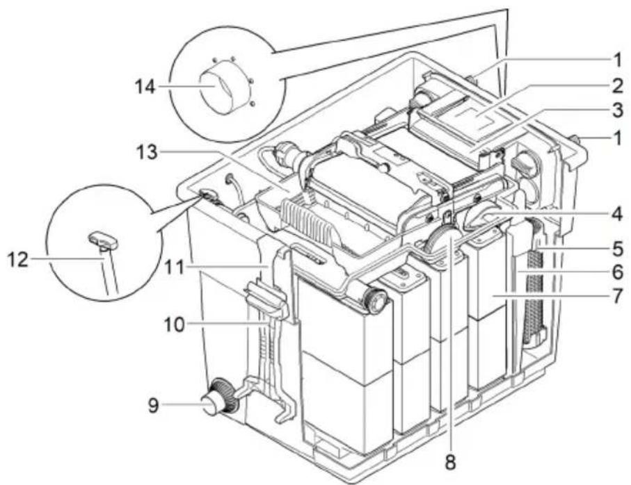
BioTec ScreenMatic ^2 40000, 60000
EN
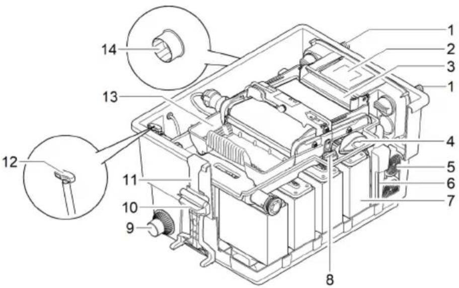
BTC0050
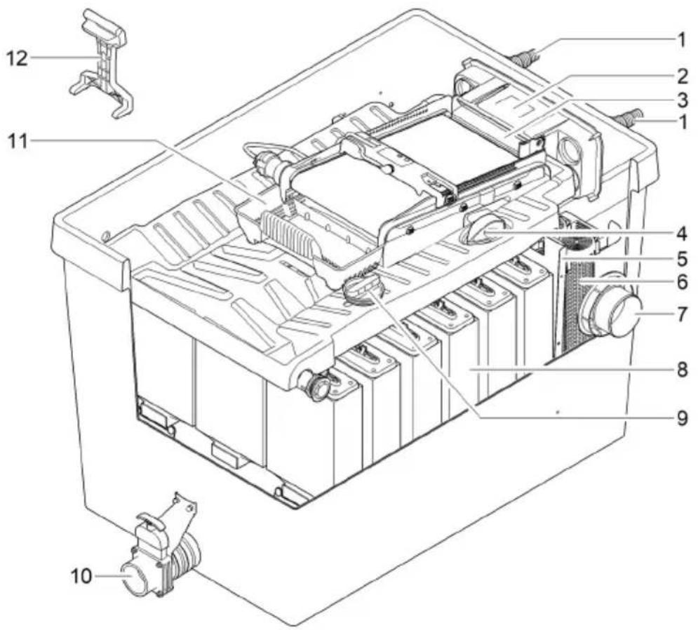
| 1 | Inlets, 2 x |
| 2 | Water distributor |
| 3 | Distributor extension |
| 4 | Brush for regularly cleaning the ScreenMatic screen |
| 5 | Substrate tubeBioTec ScreenMatic^2 40000: 2 xBioTec ScreenMatic^2 60000: 3 x |
| 6 | Separating plate, can be removed for maintenance purposes |
| 7 | Foam filter, 8 x |
| 8 | Plug for closing the outlet (14)Closing the outlet before cleaning the foam filters prevents dirty water from flowing back into the pond. |
| 9 | Dirt outlet |
| 10 | Foam cleaning device |
| 11 | Holder for the foam cleaning device |
| 12 | Dirt outlet slide valve |
| 13 | Debris tray |
| 14 | Outlet |
BioTec ScreenMatic ^2 90000
BTC0077
| 1 | Inlets, 2 x |
| 2 | Water distributor |
| 3 | Distributor extension |
| 4 | Brush for regularly cleaning the ScreenMatic screen |
| 5 | Substrate tubes, 4 x |
| 6 | Separating plate can be removed for maintenance purposes |
| 7 | Foam filter, 16 x |
| 8 | Blind plug for closing the outlet (14)• Closing the outlet before cleaning the foam filters prevents dirty water from flowing back into the pond. |
| 9 | Dirt outlet |
| 10 | Foam cleaning device |
| 11 | Holder for the foam cleaning device |
| 12 | Dirt outlet slide valve |
| 13 | Debris tray |
| 14 | Outlet |

BTC0049
| 1 | Inlets, 2 x |
| 2 | Water distributor |
| 3 | Distributor extension |
| 4 | Brush for regularly cleaning the ScreenMatic screen |
| 5 | Separating plate |
| 6 | Substrate tubes, 12 x |
| 7 | Outlet |
| 8 | Foam filter, 18 x |
| 9 | Blind plug for closing the outlet (14)• Closing the outlet before cleaning the foam filters prevents dirty water from flowing back into the pond. |
| 10 | Dirt outlet |
| 11 | Debris tray |
| 12 | Foam cleaning device |
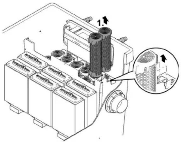
ScreenMatic rotating screen unit

BTC0056
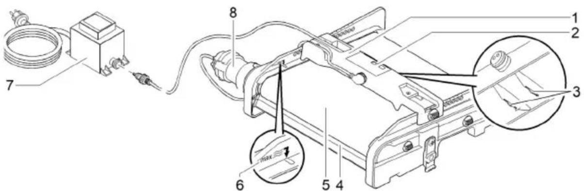
| 1 | Control system |
| 2 | Operating panel |
| 3 | Sensor underneath the control deviceWhen the sensor comes into contact with the water on the ScreenMatic screen, an automatic cleaning process is triggered. |
| 4 | Stripperscrapes the debris from the ScreenMatic screen and conveys it into the debris tray. |
| 5 | ScreenMatic screen |
| 6 | "Max. water jet" markDebris may be washed out of the debris collection tray if the water jet from the water distributor exceeds this mark. |
| 7 | TransformerVoltage supply for the control device and motor |
| 8 | MotorDrive of the ScreenMatic rotating screen unit |
Properties
- High performance flow-through filter for ponds up to 40 m ^3 , 60 m ^3 , 90 m ^3 or 140 m ^3 .
- Electrically driven ScreenMatic rotating screen for automatic removal of coarse debris.
- Low-maintenance filter due to the automatic removal of coarse debris.
- Bottom dirt outlet with slide valve for removal of dirt/debris from the filter system.
- Convenient cleaning of the foam filters directly inside the filter.
- Foam cleaning device and holder for fastening the foam cleaning device to the container.
- Perfectly tailored to the OASE AquaMax Eco filter pumps.
- Direct connection of the OASE UVC clarifiers of the Vitronic 18W/24W/36W, Bitron C and Bitron Eco series possible.
- Use of different filter media to ensure optimum colonisation of bacteria for biological filtration.
Technical data
Unit data
| BioTec ScreenMatic2 | 40000 | 60000 | 90000 | 145000 | ||
| Power pack | Primary rated voltage | V AC | 230 | 230 | 230 | 230 |
| Mains frequency | Hz | 50 | 50 | 50 | 50 | |
| Secondary rated voltage | V DC | 12 | 12 | 12 | 12 | |
| Permissible ambient temperature | °C | -10 ... +35 | -10 ... +35 | -10 ... +35 | -10 ... +35 | |
| Control system | Power consumption | W | 5 | 5 | 5 | 5 |
| Permissible ambient temperature | °C | -10 ... +35 | -10 ... +35 | -10 ... +35 | -10 ... +35 | |
| Cable length | Power pack | m | 2.10 | 2.10 | 2.10 | 2.10 |
| Control system | m | 5.00 | 5.00 | 5.00 | 5.00 | |
| Foam filter | Number of blue foam filters | pces. | 2 | 2 | 4 | 4 |
| Number of red foam filters | pces. | 3 | 3 | 6 | 7 | |
| Number of purple foam filters | pces. | 3 | 3 | 6 | 7 | |
| Special filter pellets | kg | 2.50 | 3.50 | 5 | 14.50 | |
| Removal of coarse dirt particles | μm | 300 | 300 | 300 | 300 | |
| Permissible water temperature | °C | +4 ... +35 | +4 ... +35 | +4 ... +35 | +4 ... +35 | |
| Inlet | Quantity | pces. | 2 | 2 | 2 | 2 |
| Connection, hose | mm | 25, 32, 38 | 25, 32, 38 | 25, 32, 38, 50 | 25, 32, 38, 50 | |
| G1, G11⁄4, G11⁄2 | G1, G11⁄4, G11⁄2 | G1, G11⁄4, G11⁄2, G2 | G1, G11⁄4, G11⁄2, G2 | |||
| Connection, UVC clarifier | Bitron C 36 W /55 W / 72 W / 110 W Bitron Eco 120 W / 180 W / 240 W Vitronic 18 W / 24 W / 36 W | |||||
| Outlet | Quantity | pces. | 1 | 1 | 1 | 1 |
| Connection | DN 75 | DN 75 | DN 110 | DN 110 | ||
| Dirt outlet | Quantity | pces. | 1 | 1 | 1 | 1 |
| Connection | DN 50 | DN 50 | DN 50 | DN 75 | ||
| Circulation capacity | minimum | l/h | 4000 | 6000 | 8000 | 8000 |
| Max. | l/h | 9000 | 11000 | 12500 | 17500 | |
| Maximum pond volume | Without fish population | m3 | 40 | 60 | 90 | 140 |
| With fish population | m3 | 20 | 30 | 45 | 70 | |
| Including koi carp | m3 | 10 | 15 | 22.5 | 35 | |
| Dimensions | Length | mm | 788 | 788 | 788 | 1200 |
| Width | mm | 590 | 590 | 590 | 800 | |
| Height | mm | 454 | 554 | 654 | 760 | |
| Weight | Without water | kg | 20 | 25 | 30 | 115 |
EN
Permissible water quality
| Type | Fresh water | Pool water | Salt water | |
| pH value | 6.8 ... 8.5 | 7.2 ... 8.3 | 7.5 ... 8.5 | |
| Hardness | DH | 8 ... 15 | 8 ... 15 | 20 ... 30 |
| Free chlorine | mg/l | <0.3 | <0.6 | <0.3 |
| Chloride content | mg/l | <250 | <250 | <22000 |
| Salt content | % | <0.4 | <0.4 | <4 |
| Overall dry residue | mg/l | <50 | <50 | <50 |
| Temperature | °C | +4 ... +35 | +4 ... +30 | +4 ... +28 |
Installation and connection
Access to the device
- Remove the container cover: Access to the control device.
- Hinge up the screen holder: Access to the foam filters, substrate tubes, separating plate and outlet.
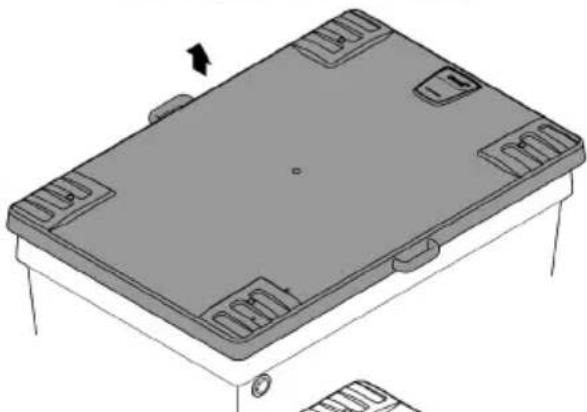
Remove the container cover
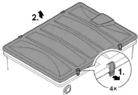
BioTec ScreenMatic ^2 40000, 60000, 90000
- Release the two locking clips, lift the cover and remove it.
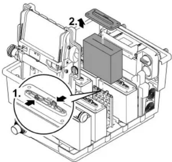
BioTec ScreenMatic ^2 145000 - Lift the cover by the handles and remove it.
- The handles are not fitted on delivery.
— Screw the handles onto the cover.
BioTec ScreenMatic ^2 40000, 60000, 90000
BioTec ScreenMatic ^2 145000
natural_image
Isometric technical drawing of a rectangular electronic component with mounting holes and a central base (no text or symbols)
natural_image
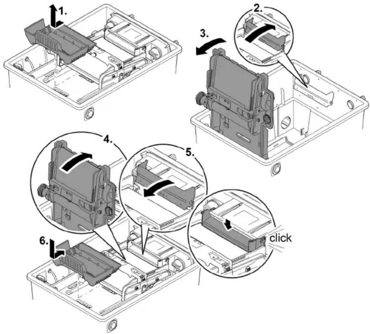
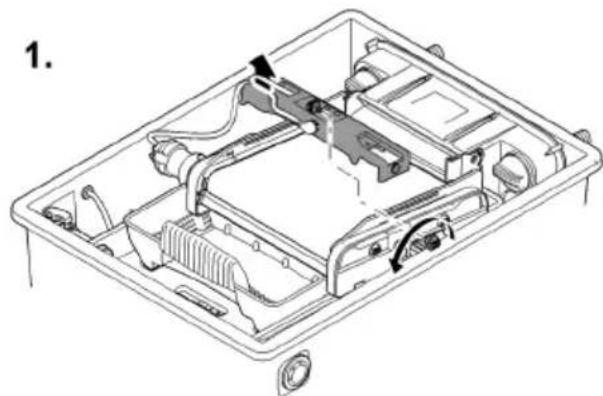
Isometric technical drawing of a rectangular electronic component with mounting holes and internal slots (no text or symbols)Hinging the screen holder up/down
How to proceed:
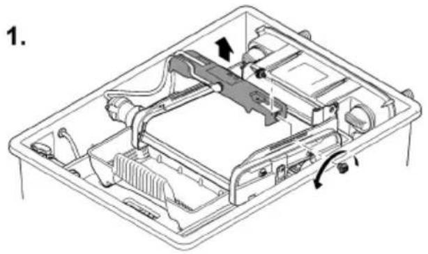
To hinge up/open
- Remove the debris tray.
- Hinge up the distributor extension.
- Hinge up the screen holder with the ScreenMatic rotating screen unit.
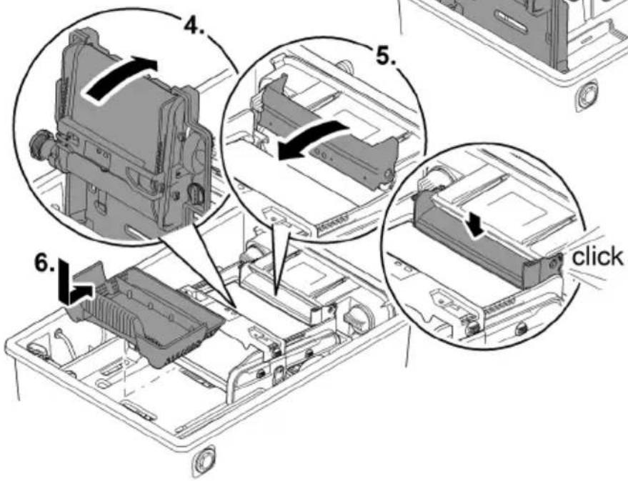
To hinge down/close
- Carefully hinge down the screen holder.
- Push the distribution extension down until it audibly engages.
- Replace the debris tray.
BTC0052

WARNING
Risk of severe injuries or death by electric shock.
Protective measures for swimming ponds:
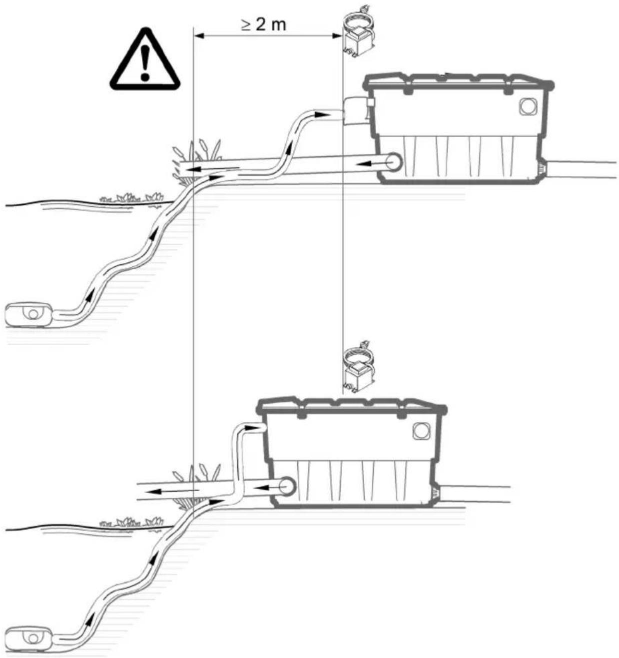
▶ Only use electrical units or installations with a rated voltage of U ≤ 12 V in the water.
Electrical installations with a rated voltage of U > 12 V must be located at a distance of at least 2 m from the water

WARNING
Due to the high weight of the unit, spinal injuries or crushing of limbs is possible when carrying the unit. The unit weighs more than 25 kg.
▶ Have at least four people carry the container exclusively on the handles to avoid spinal injuries.
▶ Protect your limbs from crushing injuries.
▶ Do not transport the container when it is filled with water.
Electrical components of the filter system operate with a rated voltage of U_DC = 12 V . The supply voltage is supplied via an external transformer connected to the mains.
- Filter system with UVC clarifier fitted:
- The filter system and transformer must be located at a distance of at least 2 m from the water.
- Filter system without UVC clarifier fitted:
- The filter system can be installed directly next to the water. The transformer must be located at a distance of at least 2 m from the water.
Optimum operating results can be obtained with careful planning, taking the ambient conditions into account.
- As the filter is very heavy when filled, it must be placed on a suitable base (at least on slabs, but preferably on a poured concrete base) to prevent it from subsiding.
- Align the base slab horizontally.
- Ensure sufficient room for movement for carrying out cleaning and maintenance work.
- Allow the dirty water to drain out into a drain or far enough away from the pond to ensure that it cannot flow back into the pond.
- Do not position the inlet into the pond higher than the outlet of the filter system (e.g. above a water course or waterfall).
Ⓐ A water course or waterfall guarantees optimum water return to the pond.
— In this way, the filtered pond water is enriched with oxygen before it is returned to the pond.
BTC0048
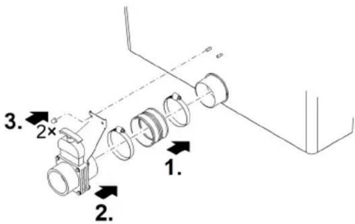
Inlets
The filter system has two inlets with stepped hose adapters.
- For connecting a filter pump
- For connecting a UVC clarifier (→ Connecting a UVC clarifier)
- If an inlet is not used, fit a closed stepped hose adapter.
- The stepped hose adapters are delivered closed.
Prerequisite:
- The container is open. (→ Remove the container cover)
- The screen holder is hinged up. (→ Hinging the screen holder up/down)
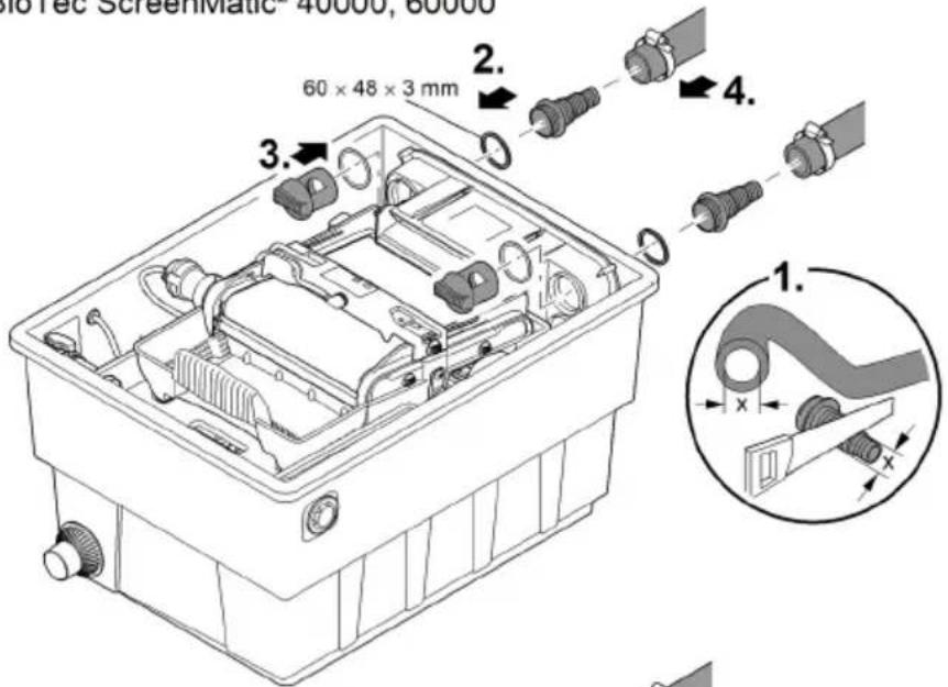
Connecting the filter pump
How to proceed:
- Shorten the stepped hose adapter to the diameter of the hose used.
— This reduces pressure losses. - Insert the stepped hose adapter with flat seal into the inlet opening.
- Screw the distributor nut with O ring onto the stepped hose adapter and hand tighten.
— BioTec ScreenMatic ^2 145000: Alternatively you can fit a 50 mm hose sleeve. - Slip the hose clip over the hose, fit the hose onto the hose connector and secure with the hose clip.
BioTec ScreenMatic ^2 40000, 60000
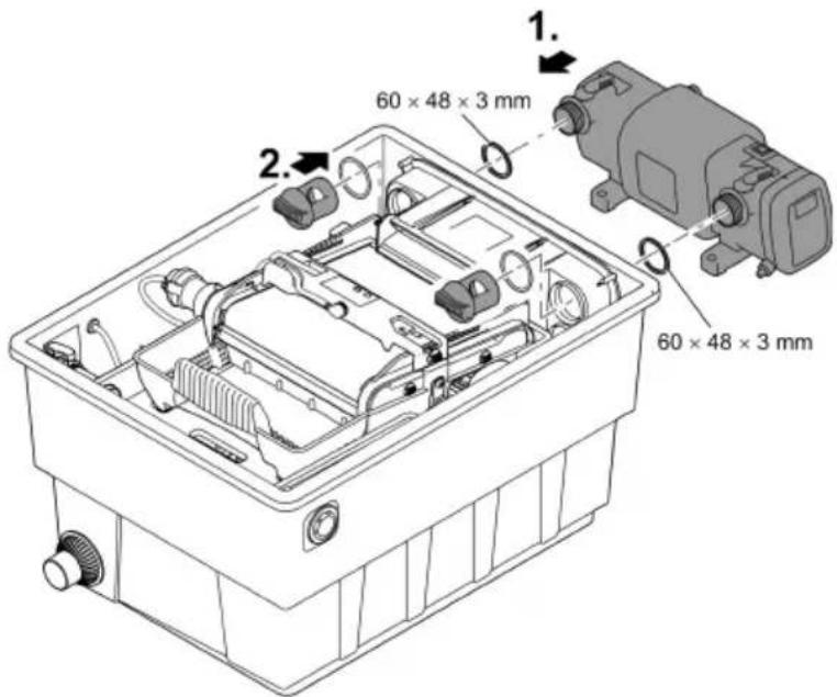
Connecting a UVC clarifier
Fitting the outlet
Prerequisite:
- The container is open. (→ Remove the container cover)
- The screen holder is hinged up. (→ Hinging the screen holder up/down)
How to proceed:
- Fit the UVC clarifier with flat seal into the inlet opening.
- Screw the distributor nut with O ring onto the stepped hose adapter and hand tighten. — Read the UVC clarifier operating instructions.
BTC0059
Outlets
- Use suitable pipes.
- Do not use any right-angled bends. Bends with a maximum angle of 45^ are very efficient.
- Standing water in pipes can freeze when there is a hard frost and cause pipes to burst. For this reason, lay the pipes and hoses with a gradient (50 mm/m) to ensure that they can run empty.
- Pipe dimensions: ( Unit data)
i Support the connected pipes. This increases the stability of pipe constructions and prevents them from sagging.
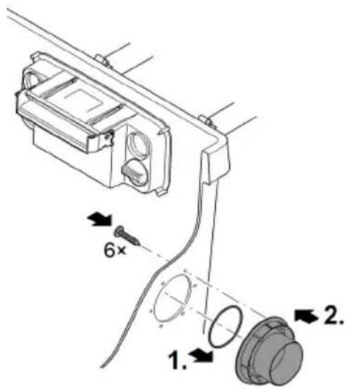
Fitting the outlet
BioTec ScreenMatic ^2 145000: The outlet is not fitted on delivery.
Prerequisite:
- The container is open. (→ Remove the container cover)
How to proceed:
-
Push the O-ring onto the outlet.
-
Position the outlet in the container wall from the outside.
- Ensure that the marking points up and is aligned with the holes in the container wall.
- Use three oval head screws to screw the outlet to the container wall from the inside.
— Tighten the screws diagonally to ensure that the seal is uniformly applied.
- If you are using a cordless screwdriver: Do not set the screwdriver to "drill" to prevent damage to the self-tapped thread. Then re-tighten the screws with a Torx screwdriver.
BTC0064
Installing the dirt outlet
BioTec ScreenMatic ^2 145000: The outlet is not fitted on delivery.
Proficlear0347
Connecting the dirt outlet
The water in the container can be drained via the DN 75 dirt outlet with a slide valve at the bottom of the container if required (for cleaning, repair, overwintering).
- Connect a suitable DN 75 pipe and drain the dirty water into the sewer system.
- Pipe dimensions: ( Unit data)
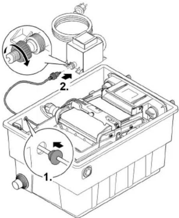
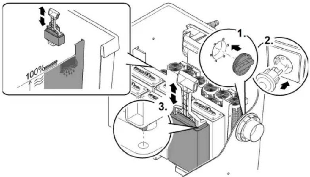
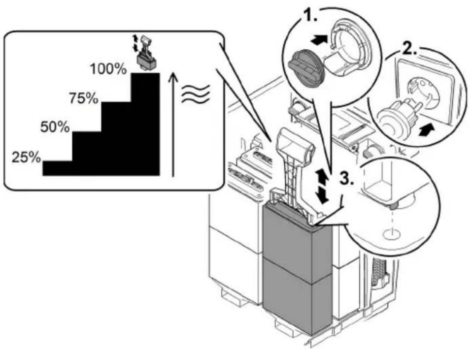
Carry out the electrical connection
How to proceed:
- Thread the connection cable through the opening in the container wall and seal off the opening using the sealing plug.
- Ensure that the connection cable inside the container is sufficiently long so that it is not subjected to tension when the ScreenMatic rotating screen unit is hinged up.
- Avoid tangling of the cable inside the container.
- Connect the plug of the connection cable to the socket on the transformer and hand-tighten the union nut.
BTC0061
Commissioning/start-up
Remove the protective film from the substrate tubes and insert the substrate tubes into the container. (→ Cleaning/replacing the substrate tubes)
— The substrate tubes are sealed in protective film on delivery.
Thoroughly clean the pond before starting up the filter system for the first time to ensure that the filter system is not overloaded by excessively soiled water. OASE recommends using the pond vacuum cleaner PondoVac for cleaning the pond.
- This cleaning measure is normally not necessary for newly installed ponds.
Biological filter starter
The foam filters take several weeks to reach their full biological cleaning effect. We recommend using the OASE filter starter Biokick to ensure fast growth of bacterial populations. Micro-organisms colonise the filter system, multiply and ensure an enhanced quality of the pond water by the decomposition of excess nutrients.
Leave the UVC clarifier switched off for at least 36 hours if you are using filter starters, medications or pond care products.
- This does not affect the effect of the agents.
Order of starting up steps
How to proceed:
- Close the slide valve of the dirt outlet.
- Check that the filter system (pipes and hoses) is complete.
- Remove the container cover.
- Connect the transformer for the control device to the power supply.
- Switch on the filter pump and UVC clarifier (if applicable).
— Ensure that the water is returned to the pond via the return pipe. - Check all pipes, hoses and their connections for leaks.
- Adjust the control device to the flow rate if necessary. (→ Aligning the control device)
- Check the function of the ScreenMatic rotating screen unit. (→ Operation)
- Fit the container cover.
— Expansion seals may leak initially until they have fully expanded on contact with water.
① Only operate the unit with the container cover in place.
To reduce pump noise, connect the pump to the pipework via flexible, pressure-resistant hose lines for fixed installation.
The substrate tubes should remain completely under water to ensure maximum effectiveness.
- If, due to the system configuration, the water level in the container is too low for this, place the top substrate tube directly into the pond, at a well-flowed place.
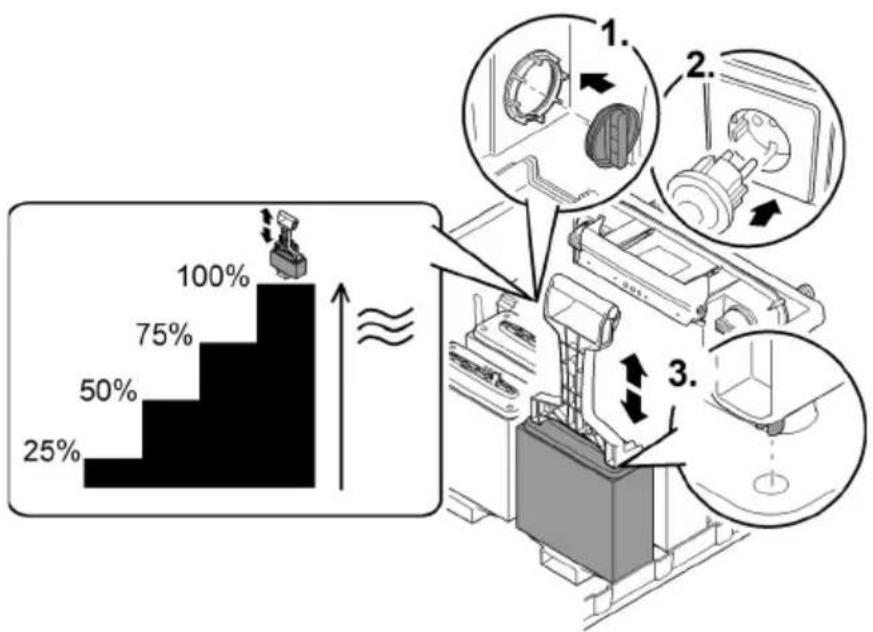
Aligning the control device
Do not align the control device until after the running-in period
- Lowering the pump into the pond may swirl up so much debris that starting up the filter system straight away could cause the ScreenMatic screen to overflow.
- The filter system requires a running-in period of 2 to 3 hours. After this, the control device can be aligned if necessary.
-
Align the control device such that the sensor only switches when a well-formed line of debris has formed on the screen.
-
A well-formed line of debris can be optimally removed by the stripper and conveyed into the debris tray.
- The stripper brush under the ScreenMatic screen collects the fine debris, which falls into the debris tray.
How to proceed:
- Remove the screw from the control device and take out the control device.
- Insert the control device into the determined position, insert the screw and hand tighten.
Aligning the control device depending on the degree of soiling of the pond
In order to prevent premature soiling of the foam filters, ensure that the dirty water does not flow beyond the "Max. water jet" mark directly into the debris tray.
- Do not change the position of the control device unless the water flows as far as or beyond the "Max. water jet" mark, even when the ScreenMatic screen has been cleaned (with the enclosed brush). (→ Cleaning/replacing the ScreenMatic screen)
Typical position of the control device
BioTec ScreenMatic ^2
| 40000 | 60000 | 90000 | 145000 | ||||
| <6000 l/h | <8 | <8000 l/h | <9 | <9000 l/h | <10 | <12000 l/h | <18 |
| >8000 l/h | >8 | >9000 l/h | >9 | >11000 l/h | >10 | >15000 l/h | >18 |
| Delivery state | 8 | Delivery state | 9 | Delivery state | 10 | Delivery state | 18 |
EN
natural_image
Technical line drawing of an electronic device casing with internal components and mounting holes (no text or symbols)
BTC0062
Operation
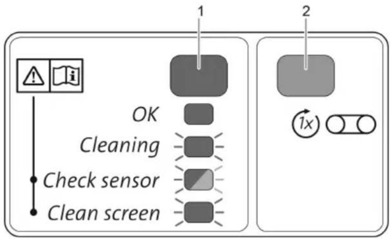
Operating panel

flowchart
graph TD
    A["OK"] --> B["Cleaning"]
    B --> C["Check sensor"]
    C --> D["Clean screen"]
    style A fill:#f9f,stroke:#333
    style B fill:#ccf,stroke:#333
    style C fill:#cfc,stroke:#333
    style D fill:#fcc,stroke:#333
    subgraph Step 1
        E["1"] --> F["2"]
    end
    subgraph Step 2
        G["1x"] --> H["Circle with X"]
    end
BTC0046
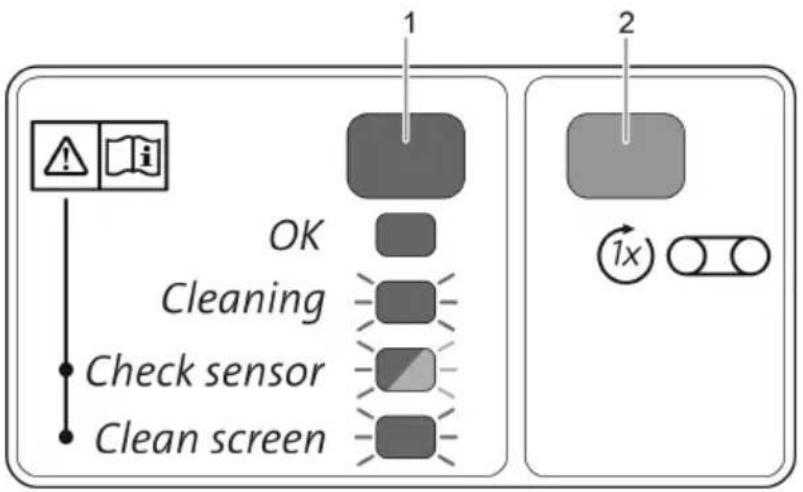
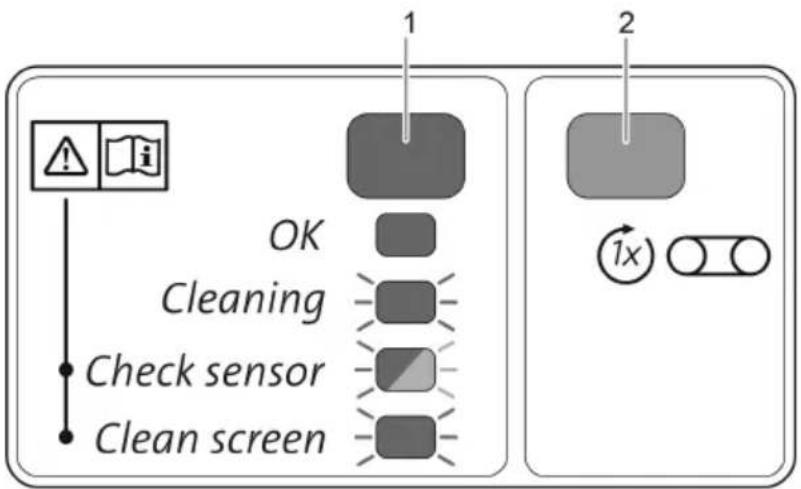
1 LED, 2 colours
| Lit green | The ScreenMatic rotating screen unit is operational |
| Flashing green | Cleaning active |
| Flashes green/red | Malfunction (→System messages) |
| Flashing red | Malfunction (→System messages) |
2 Button, start/stop manual cleaning (→ Manual cleaning)
Manual cleaning
Proceed as follows
| Press for 1 s. | The ScreenMatic screen is rotated by 1 revolution. • Press the button again for 1s: The rotational movement stops prematurely. |
Automatic cleaning
Due to the build-up of debris the water level on the ScreenMatic screen also rises. When the sensor in the control device comes into contact with the water, it triggers the rotational movement of the ScreenMatic screen.
By briefly moving the ScreenMatic screen back several times a larger line of debris is formed, which can be better removed by the stripper.
| Sequence of an automatic cleaning cycle | Rotational movement of the ScreenMaticscreen |
| Normal soiling | |
| 1. Contact of the sensor with water | Brief movement backward |
| 2. Contact of the sensor with water | Brief movement backward |
| 3. Contact of the sensor with water | Brief movement backward |
| 4. Contact of the sensor with water | One rotation forward• The debris is conveyed into the debris tray. |
| Heavy soiling or incorrectly aligned control device (per-manently high water level on the ScreenMatic screen) | |
| 1. Contact of the sensor with water | Brief movement backward, then one rotation forward• The debris is conveyed into the debris tray. |
Time-dependent cleaning
The ScreenMatic rotating screen unit executes a cleaning cycle after a set interval depending on the ambient temperature. This ensures cleaning at regular intervals
- if the sensor is soiled or defective,
- if there is very little soiling on the screen and/or low flow rates (e.g. when the SFC of the filter pump is activated).
| Ambient temperature | Interval | Rotational movement of the ScreenMaticscreen |
| ≤ 10 °C | 6 hours | One rotation forward |
| 10 °C ... 20 °C | 4 hours | The debris is conveyed into the debris tray. |
| ≥ 20 °C | 3 hours |
System messages
| LED | Malfunction | Possible cause | Remedy | Reset the system message |
| Flashes green/red | No automatic cleaning cycle within 48 hours | Sensor soiled | Clean the sensor.Descale the sensor. | Automatic reset after remedy of malfunction |
| No dirty water, cleaning is not necessary | - | |||
| No flow of water | Filter pump is not operating | Start up the filter pump. | ||
| No water detected by the sensor | Control device incorrectly positioned | Correctly position the control device | ||
| Control device defective | Replace the control device. | |||
| Insufficient conductivity of the water | Increase the water hardness with OptiPond | |||
| Insufficient pump capacity | Adjust the pump capacity accordingly | |||
| Flashing red | 20 automatic cleaning cycles in succession | ScreenMatic screen soiled | Start manual the cleaning cycle and use a brush to clean the ScreenMatic screen on the side of the water distributor(→ Manual cleaning)Clean the ScreenMatic screen from the inside if the mesh is clogged by a biofilm(→ Cleaning/replacing the ScreenMatic screen) | Automatic reset after remedy of malfunction |
| Sensor soiled | Clean the sensor. | |||
| Control device incorrectly positioned | Correctly position the control device | |||
| Pump capacity too high | Adjust the pump capacity accordingly | |||
| Flashing green | ScreenMatic screen not rotating although a manual cleaning cycle was triggered. | Motor cable plug not connected or incorrectly connected to the control device | Connect the plug, check that it is correctly seated. | - |
| Motor defective | Replace motor | |||
| Off | ScreenMatic screen not rotating although a manual cleaning cycle was triggered. | Connection cable plug not connected or incorrectly connected to the transformer | Connect the plug, check that it is correctly seated. | - |
| Transformer not connected to the mains voltage | Connect the transformer to the mains voltage. | |||
| Transformer defective | Replace transformer | |||
| Control device defective | Replace the control device. |
Maintenance and cleaning
WARNING
Risk of severe injuries or death by electric shock.
▶ Disconnect all electrical devices in the water from the power supply before reaching into the water.
▶ Disconnect the unit from the mains before you start working on it.
- Do not use aggressive cleaning agents or chemical solutions as they could attack the housing or impair the function of the unit.
- Recommended cleaning agent for removing stubborn limescale deposits:
— Pump cleaning agent PumpClean from OASE.
— Vinegar- and chlorine-free household cleaning agent.
• After cleaning, thoroughly rinse all parts in clean water.
Regular cleaning work
• Empty the debris tray:
— The cleaning cycle is dependent on the degree of soiling of the pond.
- Remove the debris tray. (→ Hinging the screen holder up/down)
- Clean the ScreenMatic screen:
- If the ScreenMatic screen becomes clogged, clean the ScreenMatic screen downstream of the water distributor using the brush. For this, manually activate the SceenMatic screen. (→ Manual cleaning)
- Carry out intensive cleaning with the pump cleaning agent PumpClean from OASE: (→ Cleaning/replacing the ScreenMatic screen)
Cleaning foam filters
- It is necessary to clean the foam filters as soon as the water exceeds the 100% mark on the separating plate.
- Do not use chemical cleaning agents, as these will kill the filter bacteria.
Prerequisite:
• The filter pump is switched off.
- The container is open. (→ Remove the container cover)
- The screen holder is hinged up. (→ Hinging the screen holder up/down)
- BioTec ScreenMatic ^2 90000: Separating plate has been pulled out and the substrate tubes have been removed. (→ Cleaning/replacing the substrate tubes)
- The water level in the container has lowered to the height of the outlet or below.
BioTec ScreenMatic ^2 40000, 60000, 90000
How to proceed:
- Insert the plug into the outlet from the inside to close off the outlet.
- Remove the separating plate to facilitate access if applicable.
- Switch on the filter pump until the foam filters are covered with water, then switch off the filter pump.
- Compress all foam filters several times with the foam cleaning device.
- Allow the dirty water to drain away.
- Open the dirt outlet slide valve and close it again when the container is empty.
- Repeat steps 2 ... 4 as required.
- Rinse the container with clear water to remove any loosened dirt particles. To do this, first carry out step 2, then step 4.
- Remove the plug from the inside of the outlet.
- Close the dirt outlet slide valve.
- Hinge down the screen holder ( Hinging the screen holder up/down), insert the debris tray and switch on the filter pump.
BioTec ScreenMatic ^2 40000, 60000
bar
| Step | Percentage (%) | |---|---| | 1 | 25 | | 2 | 50 | | 3 | 75 | | 4 | 100 |EN
BTC0053
BioTec ScreenMatic ^2 90000

bar
| Category | Percentage (%) | | :--- | :--- | | Top Bar | 100 | | Bottom Bar | 75 | | Bottom Left Bar | 50 | | Bottom Right Bar | 25 | The diagram illustrates a step-by-step process with three labeled steps (1, 2, 3) indicating sequential stages of processing or assembly. The top bar is visually scaled to represent cumulative percentages, while the bottom bars are shown as arrows pointing to specific steps. No numerical values or units are provided; the visual emphasizes relative proportions and progression across these steps.BTC0082
BioTec ScreenMatic ^2 145000
How to proceed:
- Insert the plug into the outlet from the inside to close off the outlet.
- Switch on the filter pump until the foam filters are covered with water, then switch off the filter pump.
- Compress all foam filters several times with the foam cleaning device.
- Allow the dirty water to drain away.
- Open the dirt outlet slide valve and close it again when the container is empty.
- Repeat steps 2 ... 4 as required.
- Rinse the container with clear water to remove any loosened dirt particles. To do this, first carry out step 2, then step 4.
- Remove the plug from the inside of the outlet.
- Close the dirt outlet slide valve.
- Hinge down the screen holder (→ Hinging the screen holder up/down), insert the debris tray and switch on the filter pump.
BTC0079
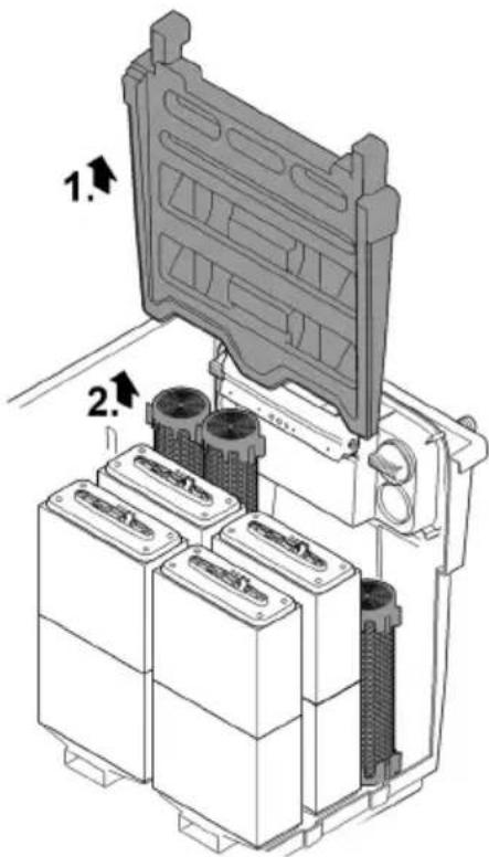
Cleaning/replacing the substrate tubes
The substrate tubes are filled with zeolite on delivery. OASE recommends replacing the zeolite with Phosless when the bacteria are established and the foam filters are fully effective.
Prerequisite:
• The filter pump is switched off.
- The container is open. (→ Remove the container cover)
- The screen holder is hinged up. (→ Hinging the screen holder up/down)
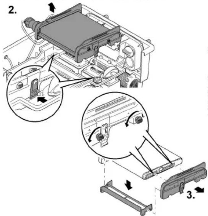
BioTec ScreenMatic ^2 40000, 60000
How to proceed:
- Remove the separating plate.
- Remove the substrate tubes and clean them or replace their contents.
— BioTec ScreenMatic ^2 40000: Two substrate tubes
— BioTec ScreenMatic ^2 60000: Three substrate tubes - When inserting, push the substrate tubes against the wall opposite to the outlet.
BTC0055
BioTec ScreenMatic ^2 90000
How to proceed:
-
Remove the separating plate.
-
Remove the substrate tubes and clean them or replace their contents.
— BioTec ScreenMatic ^2 90000: Four substrate tubes
- Two substrate tubes each to the left of the outlet and two substrate tubes each to the right of the outlet.
BTC008
BioTec ScreenMatic ^2 145000
How to proceed:
- Remove the substrate tubes individually and clean them or replace their contents. — BioTec ScreenMatic ^2 145000: Twelve substrate tubes
EN
BTC008C
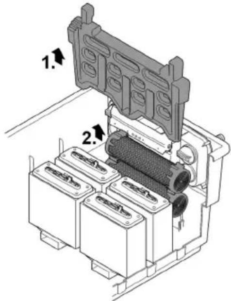
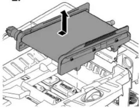
Cleaning/replacing the ScreenMatic screen
Prerequisite:
• The filter pump is switched off.
- The container is open. (→ Remove the container cover)
- The debris tray is removed. (→ Hinging the screen holder up/down)
How to proceed:
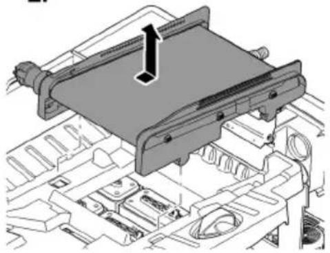
-
Remove the screw for fastening the control device, remove the control device and place it carefully to the side.
-
If necessary, disconnect the motor cable plug from the control device.
— Mark the position of the control device on a side section for reassembly. -
Take the ScreenMatic rotating screen unit out of the screen holder.
-
Biotec ScreenMatic ^2 40000, 60000, 90000: Press the locking clips on both sides and remove the ScreenMatic rotating screen unit.
-
Biotec ScreenMatic ^2 145000: Press the ScreenMatic rotating screen unit in the direction of the water distributor and remove.
-
Undo the nuts on the side section, and remove the side section and stripper.
-
Release the clamping lever and remove the ScreenMatic screen.
— Thoroughly clean the stripper.
- Thoroughly clean both sides of the ScreenMatic screen. Replace the ScreenMatic screen if necessary.
- Use the pump cleaning agent PumpClean from OASE.
- Reassemble the ScreenMatic rotating screen unit in the reverse order and place it into the screen holder.
— When tensioning the ScreenMatic screen, ensure that the clamping lever engages.
natural_image
Technical line drawing of an electronic device casing with internal components and directional arrows indicating movement (no text or symbols)BioTec ScreenMatic ^2 40000, 60000, 90000
BioTec ScreenMatic ^2 145000


natural_image
Technical diagram of a mechanical assembly with no visible text or symbols
BTC006C
Replacing foam filters
Prerequisite:
• The filter pump is switched off.
- The container is open. (→ Remove the container cover)
- The screen holder is hinged up. (→ Hinging the screen holder up/down)
How to proceed:
- Press both locking clips on the foam holder.
- Remove the foam holder plate and foam filter.
- Push a new foam filter onto the foam holder, fit the foam holder plate and push down until the two locking clips engage in the foam holder plate.
i Recommendation regarding the replacement of foam filters:
- Only partially replace the foam filters at intervals of at least a week so as not to impair the biological cleaning action too much.
- Never replace more than 50% of the foam filters at any one time.
BTC0054
Storage/winter protection
The unit is protected from frost (e.g. stored in a garage or other enclosure)
The unit can be operated as long as the water temperature does not go below +4 °C.
The deeper areas of the pond have a water temperature of approx. +4 °C in winter and are essential for the fish. By taking the following measures it is possible to reduce the cooling effect on the water of the circulation by the filter system:
- Position the pump nearer to the surface of the water so that only colder water closer to the surface of the pond enters the pump.
• Insulate the return pipes from the filter system into the pond. - Do not allow water to flow into the pond via a water course.
The unit is not protected from frost (e.g. outdoor installation)
Shut down the unit at water temperatures below +8 °C or at the latest when freezing temperatures are expected.
- Drain the water remaining in the unit, in the hoses, pipes and connections as much as possible.
- Open all slide valves to prevent water from pooling.
- Cover the container to prevent rain water from entering.
- Protect any lines and slide valves from which you cannot drain the water against freezing.
Malfunction remedy
| Malfunction | Possible cause | Remedy |
| No flow of water | Filter pump not switched on. | Switch on the filter pump, connect the power plug. |
| Supply to filter system or return to pond blocked. | Clean the supply and/or return. | |
| Water flow insufficient | Hose kinked or clogged | Check, clean or replace the hose if necessary. |
| Excessive loss in the hoses due to friction | Reduce hose length to minimum necessary | |
| Insufficient pump capacity | Adjust the pump capacity accordingly | |
| Water remains cloudy | Insufficient circulation of the water | Adjust the pump capacity accordingly |
| The water is extremely soiled. | ·Optimise the circulation of the water in the pond.·Remove algae and leaves from the pond.·Change the water.·If the water is particularly contaminated, change 30 % of the water to avoid damage to the fish. | |
| Too many pond animals | Reduce number of pond animalsGuide value: approx. 600 mm fish length per 1m^3 pond water | |
| ScreenMatic screen is clogged | Clean or replace the ScreenMatic screen. | |
| Foam filters soiled | Clean foam filters | |
| No water at the pond inlet | Pond inlet blocked | Clean the pond inlet. |
| Filter pump is not operating. | Start up the filter pump. | |
| Water level in the container too low, foam filters are not completely immersed in water. | The water level is initially lower when new foam filters are fitted as they have not yet been colonised by bacteria. | ·It takes several weeks for the bacteria to become established and the foam filters to become fully effective.·Use OASE filter starter Biokick to speed up the colonisation of bacteria. |
| The separating plate is missing.(Only BioTec ScreenMatic ^2 40000, 60000, 90000) | Insert the separating plate. | |
| Increased noise | Noise of water at the outlet due to insufficient aeration | Insert a tee into the discharge pipe with the opening pointing up for aeration. |
EN
Wear parts
- Foam filters
- Substrate tubes
- ScreenMatic screen
Disposal
NOTE
Do not dispose of this unit with household waste.
▶ Dispose of the unit by using the return system provided for this purpose.
▶ Should you have questions, please contact your local disposal company. They will give you information on how to correctly dispose of the unit.
▶ Render the unit unusable by cutting the cables.

AVERTISSEMENT
FR
BTC0050
BTC0077
BTC0049
BTC0056
natural_image
Isometric technical drawing of a mechanical component with mounting holes and a central base (no text or symbols)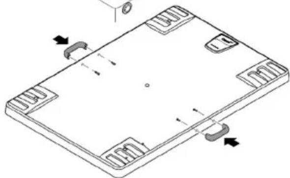
natural_image
Isometric line drawing of a rectangular electronic component with mounting holes and internal slots (no text or symbols)natural_image
Technical line drawing of an electronic device chassis with internal components and mounting holes (no text or symbols)
BTC0052

AVERTISSEMENT
BTC0061
Mise en service
natural_image
Technical line drawing of an electronic device chassis with internal components and mounting holes (no text or symbols)
BTC0062
Utilisation
Tableau de commande

flowchart
graph TD
    A["OK"] --> B["Cleaning"]
    B --> C["Check sensor"]
    C --> D["Clean screen"]
    E["1"] --> F["2"]
    G["1x"] --> H["○ ○"]
BTC0046
1 LED, bicolore
BTC0055
BioTec ScreenMatic ^2 90000
BTC008
BioTec ScreenMatic ^2 145000
FR
BTC008C
Nettoyage/Remplacement de la crépine-ScreenMatic
Prérequis :
natural_image
Technical line drawing of an electronic device casing with internal components and directional arrows indicating movement (no text or symbols)BioTec ScreenMatic ^2 40000, 60000, 90000
BioTec ScreenMatic ^2 145000


natural_image
Technical diagram of a mechanical assembly with no visible text or symbols
BTC006C
BTC0050
BTC0077
BTC0049
BTC0056
natural_image
Isometric technical drawing of a rectangular electronic component with mounting holes and a central base (no text or symbols)
natural_image
Isometric line drawing of a rectangular electronic component with mounting holes and internal slots (no text or symbols)BTC0061
Ingebruikname
natural_image
Technical line drawing of an electronic device casing with internal components and mounting holes (no text or symbols)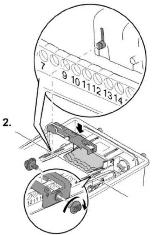
Bediening
Bedieningspaneel
flowchart
graph TD
    A["OK"] --> B["Cleaning"]
    B --> C["Check sensor"]
    C --> D["Clean screen"]
    E["1"] --> F["2"]
    G["1x"] --> H["Circle icon"]
BTC0046
1 LED, 2-kleurig
bar
| Category | Percentage (%) | | :--- | :--- | | Top Bar | 100 | | Bottom Bar | 50 | | Right Arrow (approx) | 25 | The chart visually represents a cumulative percentage from 25% to 100%, with arrows pointing to three labeled steps (1, 2, 3). The bottom section includes icons of a device and a magnified inset showing the process sequence.BTC0082
BioTec ScreenMatic ^2 145000
Zo gaat u te werk:
BioTec ScreenMatic ^2 90000
Zo gaat u te werk:
BTC008
BioTec ScreenMatic ^2 145000
Zo gaat u te werk:
NL
BTC008C
ScreenMatic-zeef reinigen/vervangen
Voorwaarde:
natural_image
Technical line drawing of an electronic device casing with internal components and directional arrows indicating movement (no text or symbols)BioTec ScreenMatic ^2 40000, 60000, 90000
BioTec ScreenMatic ^2 145000

natural_image
Technical diagram of a mechanical assembly with no visible text or symbols
BTC006C
Filtersponzen vervangen
Voorwaarde:
BTC0054
Opslag/overwinteren
BTC0050
BTC0077
BTC0049
BTC0056
natural_image
Isometric technical drawing of a mechanical component with mounting holes and a central base (no text or symbols)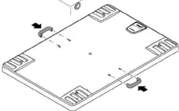
natural_image
Isometric technical drawing of a rectangular electronic component with mounting holes and internal slots (no text or symbols)BTC0061
Puesta en marcha
natural_image
Technical line drawing of an electronic device casing with internal components and mounting holes (no text or symbols)
Operación
Panel de control

flowchart
graph TD
    A["OK"] --> B["Cleaning"]
    B --> C["Check sensor"]
    C --> D["Clean screen"]
    E["1"] --> F["2"]
    G["1x"] --> H["Circle with arrow"]
BTC0046
1 LED, 2 colores
bar
| Category | Percentage (%) | | :--- | :--- | | Top Bar | 100 | | Bottom Bar | 25 | | Middle Bar | 75 | | Right Arrow | ≈ | | Step | Description | | :--- | Description | | 1 | Top Bar (approx. 100%) | | 2 | Middle Bar (approx. 50%) | | 3 | Bottom Bar (approx. 25%) |BioTec ScreenMatic ^2 145000
BioTec ScreenMatic2 90000
BTC008
BioTec ScreenMatic ^2 145000
natural_image
Technical line drawing of an electronic device casing with internal components and directional arrows indicating movement (no text or symbols)BioTec ScreenMatic ^2 40000, 60000, 90000
BioTec ScreenMatic ^2 145000


natural_image
Technical diagram of a mechanical assembly with no visible text or symbols
BTC006C
BTC0054
BTC0050
BTC0077
BTC0049
BTC0056
natural_image
Isometric technical drawing of a mechanical component with mounting holes and a central base (no text or symbols)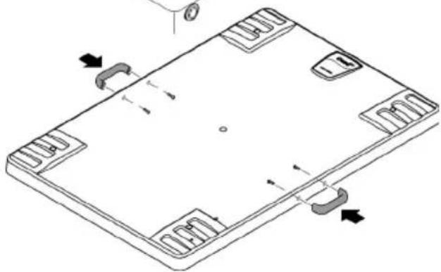
natural_image
Isometric line drawing of a rectangular electronic device with mounting holes and internal circuitry (no text or symbols)BTC0061
natural_image
Technical line drawing of an electronic device casing with internal components and mounting holes (no text or symbols)
Operação
Painel de controlo

flowchart
graph TD
    A["OK"] --> B["Cleaning"]
    B --> C["Check sensor"]
    C --> D["Clean screen"]
    E["1"] --> F["2"]
    G["1x"] --> H["Circle icon"]
BTC0046
1 LED, 2 cores
bar
| Category | Percentage (%) | | :--- | :--- | | Top Bar | 100 | | Bottom Bar | 50 | | Right Arrow (approx) | 25 | The diagram illustrates a step-by-step process with three labeled steps: Step 1 (top-right), Step 2 (middle-left), and Step 3 (bottom-right). The top bar is visually scaled to 100% and the bottom bar to 25%. The diagram includes icons of a device, a computer monitor, and a hand tool, suggesting a process flow or manufacturing workflow.BTC0082
BioTec ScreenMatic ^2 145000
BTC0055
BioTec ScreenMatic ^2 90000
PT
BTC008
BioTec ScreenMatic ^2 145000
BTC008C
Limpar/substituir o crivo ScreenMatic
Condição prévia:
natural_image
Technical line drawing of an electronic device casing with internal components and directional arrows (no text or symbols)BioTec ScreenMatic ^2 40000, 60000, 90000
BioTec ScreenMatic ^2 145000


natural_image
Technical diagram of a mechanical assembly with no visible text or symbols
BTC006C
Substituir os filtros de espuma
Condição prévia:
BTC0054
Armazenar/Invernar
BTC0050
BTC0077
BTC0049
BTC0056
natural_image
Isometric technical drawing of a rectangular electronic component with mounting holes and a central base (no text or symbols)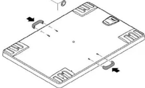
natural_image
Isometric line drawing of a rectangular electronic component with mounting holes and internal slots (no text or symbols)BTC0051
BTC0061
Messa in funzione
natural_image
Technical line drawing of an electronic device casing with internal components and mounting holes (no text or symbols)
Impiego
Quadro comando

flowchart
graph TD
    A["OK"] --> B["Cleaning"]
    B --> C["Check sensor"]
    C --> D["Clean screen"]
    E["1"] --> F["2"]
    G["1x"] --> H["Circle icon"]
BTC0046
1 LED, a 2 colori
bar
| Category | Percentage (%) | | :--- | :--- | | Top Bar | 100 | | Bottom Bar | 50 | | Right Arrow (approx) | 25 | The diagram illustrates a step-by-step process with three labeled steps: Step 1 (top-right), Step 2 (middle-left), and Step 3 (bottom-right). The top bar is visually scaled to 100% and the bottom bar to 25%. The diagram includes icons of a device, a computer monitor, and a hand tool, suggesting a process flow or manufacturing workflow.BTC0082
BioTec ScreenMatic ^2 145000
BTC0055
BioTec ScreenMatic ^2 90000
IT
BTC008
BioTec ScreenMatic ^2 145000
BTC008C
natural_image
Technical line drawing of an electronic device casing with internal components and directional arrows (no text or symbols)BioTec ScreenMatic ^2 40000, 60000, 90000
BioTec ScreenMatic ^2 145000


natural_image
Mechanical assembly diagram showing a component with a 3D arrow indicating direction (no text or symbols present)
BTC006C
BTC0054
BTC0050
BTC0077
BTC0049
BTC0056
natural_image
3D technical illustration of a rectangular electronic component with mounting holes and a central base (no text or symbols)
natural_image
Isometric line drawing of a rectangular electronic component with mounting holes and internal slots (no text or symbols)BTC0051
BTC0061
Ibrugtagning
natural_image
Technical line drawing of an electronic device casing with internal components and a handle (no text or symbols)
BTC0062
Betjening
Betjeningsfelt

flowchart
graph TD
    A["OK"] --> B["Cleaning"]
    B --> C["Check sensor"]
    C --> D["Clean screen"]
    style A fill:#f9f,stroke:#333
    style B fill:#ccf,stroke:#333
    style C fill:#cfc,stroke:#333
    style D fill:#fcc,stroke:#333
    subgraph Step 1
        E["1"] --> F["2"]
    end
    subgraph Step 2
        G["1x"] --> H["Circle with X"]
    end
BTC0046
DA
1 LED, 2-farvet
bar
| Category | Percentage (%) | | :--- | :--- | | Top Bar | 100 | | Bottom Bar | 75 | | Bottom Bar (Right) | 50 | | Bottom Bar (Left) | 25 |BTC0082
BioTec ScreenMatic ^2 145000
Sådan gør du:
BTC0055
BioTec ScreenMatic ^2 90000
Sådan gør du:
DA
BTC008
BioTec ScreenMatic ^2 145000
Sådan gør du:
BTC008C
natural_image
Technical line drawing of an electronic device casing with internal components and directional arrows indicating movement (no text or symbols)BioTec ScreenMatic ^2 40000, 60000, 90000
BioTec ScreenMatic ^2 145000


natural_image
Mechanical assembly diagram showing a component with a 3D arrow indicating direction (no text or symbols present)
BTC006C
Udskift filterskum
Forudsætning:
BTC0054
Opbevaring/overvintring
Apparatet står beskyttet mod frost (f.eks. i en garage eller carport)
BTC0050
BTC0077
BTC0049
BTC0056
BTC0064
BTC0061
Igangsetting
natural_image
Technical line drawing of an electronic device casing with internal components and mounting holes (no text or symbols)
BTC0062
Bruk
Betjeningsfelt

flowchart
graph TD
    A["OK"] --> B["Cleaning"]
    B --> C["Check sensor"]
    C --> D["Clean screen"]
    E["1"] --> F["2"]
    G["1x"] --> H["Circle icon"]
BTC0046
1 LED, 2-target
2 Knapp, starter/stopper manuell rengjøring (→ Manuell rengjøring)
Manuell rengjøring
Slik går du frem
bar
| Category | Percentage (%) | | :--- | :--- | | Top Bar | 100 | | Bottom Bar | 50 | | Right Arrow (approx) | 25 | The diagram visually represents a multi-step process: (1) Initial stage, (2) Processing, (3) Distribution, and (4) Installation. The process is labeled with step numbers (1, 2, 3).BTC0082
BioTec ScreenMatic ^2 145000
Slik går du frem:
BTC0055
BioTec ScreenMatic ^2 90000
Slik går du frem:
NO
BTC008
BioTec ScreenMatic ^2 145000
Slik går du frem:
BTC008C
Rengjøre/skifte ScreenMatic-filter
Forutsetning:
natural_image
Technical line drawing of an electronic device casing with internal components and directional arrows indicating movement (no text or symbols)BioTec ScreenMatic ^2 40000, 60000, 90000
BioTec ScreenMatic ^2 145000


natural_image
Technical diagram of a mechanical assembly with no visible text or symbols
BTC006C
Skifte skumfilter
Forutsetning:
BTC0054
Lagring/overvintring
Apparatet står beskyttet mot frost (f.eks. i en garasje eller i en innhengning)
BTC0050
BTC0077
BTC0049
BTC0056
BTC0061
Driftstart
natural_image
Technical line drawing of an electronic device casing with internal components and a handle (no text or symbols)
BTC0062
2 Knapp, starta/stoppa manuell rengöring (→ Manuell rengöring)
Manuell rengöring
Gör så här
Beskrivning
Håll intryckt i1s.
ScreenMatic-silen vrids fram med 1varv.
BTC0055
BioTec ScreenMatic ^2 90000
Gör så här:
SV
BTC008
BioTec ScreenMatic ^2 145000
Gör så här:
BTC008C
Rengör/byt ut ScreenMatic-silen
Förutsättning:
natural_image
Technical line drawing of an electronic device casing with internal components and directional arrows (no text or symbols)BioTec ScreenMatic ^2 40000, 60000, 90000
BioTec ScreenMatic ^2 145000


natural_image
Technical diagram of a mechanical assembly with no visible text or symbols
BTC006C
Byta ut filtersvamparna
Förutsättning:
BTC0054
BTC0050
BTC0077
BTC0049
BTC0056
natural_image
Isometric technical drawing of a rectangular electronic component with mounting holes and a central base (no text or symbols)
natural_image
Isometric technical drawing of a rectangular electronic component with mounting holes and internal slots (no text or symbols)BTC0051
FI
BTC0061
Käyttöönotto
natural_image
Technical line drawing of an electronic device casing with internal components and mounting holes (no text or symbols)
BTC0062
Käyttö
Käyttökenttä
flowchart
graph TD
    A["OK"] --> B["Cleaning"]
    B --> C["Check sensor"]
    C --> D["Clean screen"]
    style A fill:#f9f,stroke:#333
    style B fill:#ccf,stroke:#333
    style C fill:#cfc,stroke:#333
    style D fill:#fcc,stroke:#333
BTC0046
1 LED, 2-värinen
BTC0055
BioTec ScreenMatic ^2 90000
Toimit näin:
FI
BTC008
BioTec ScreenMatic ^2 145000
Toimit näin:
BTC008C
natural_image
Technical line drawing of an electronic device casing with internal components and directional arrows indicating movement (no text or symbols)BioTec ScreenMatic ^2 40000, 60000, 90000
BioTec ScreenMatic ^2 145000


natural_image
Technical diagram of a mechanical assembly with no visible text or symbols
BTC006C
BTC0054
BTC0050
BTC0077
BTC0049
BTC0056
natural_image
Technical line drawing of an electronic device chassis with internal components and mounting holes (no text or symbols)

BTC0052

FIGYELMEZTETÉS
BTC0064
Üzembe helyezés
natural_image
Technical line drawing of an electronic device casing with internal components and mounting holes (no text or symbols)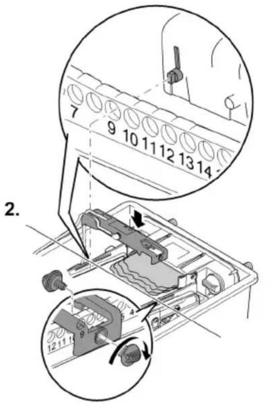
BTC0062
Kezelés
Kezelőmező

flowchart
graph TD
    A["OK"] --> B["Cleaning"]
    B --> C["Check sensor"]
    C --> D["Clean screen"]
    style A fill:#f9f,stroke:#333
    style B fill:#ccf,stroke:#333
    style C fill:#cfc,stroke:#333
    style D fill:#fcc,stroke:#333
    subgraph Step 1
        E["1"] --> F["2"]
    end
    subgraph Step 2
        G["1x"] --> H["Circle with X"]
    end
BTC0046
1 LED, 2-színű
bar
| Category | Percentage (%) | | :--- | :--- | | Top Bar | 100 | | Bottom Bar | 25 | | Middle Bar | 75 | | Right Arrow (approx) | ≈ | | Step | Description | | :--- | Description | | 1 | Top Bar (approx) | | 2 | Middle Bar (approx) | | 3 | Right Arrow (approx) |BTC0082
BioTec ScreenMatic ^2 145000
BTC0055
BioTec ScreenMatic ^2 90000
HU
BTC008
BioTec ScreenMatic ^2 145000
BTC008C
natural_image
Technical line drawing of an electronic device casing with internal components and directional arrows indicating movement (no text or symbols)BioTec ScreenMatic ^2 40000, 60000, 90000
BioTec ScreenMatic ^2 145000


natural_image
Technical diagram of a mechanical assembly with no visible text or symbols
BTC006C
BTC0054
Tárolás/Telelés
BTC0050
BTC0077
BTC0049
BTC0056
natural_image
Isometric technical drawing of a rectangular electronic component with mounting holes and a central base (no text or symbols)
natural_image
Isometric technical drawing of a rectangular electronic component with mounting holes and internal slots (no text or symbols)BTC0051
PL
BTC0061
Uruchomienie
natural_image
Technical line drawing of an electronic device casing with internal components and mounting holes (no text or symbols)
BTC0062
Obstuga
Panel obstugowy

flowchart
graph TD
    A["OK"] --> B["Cleaning"]
    B --> C["Check sensor"]
    C --> D["Clean screen"]
    E["1"] --> F["2"]
    G["1x"] --> H["Circle icon"]
BTC0046
bar
| Category | Percentage (%) | | :--- | :--- | | Top Bar | 100 | | Bottom Bar | 50 | | Right Arrow (approx) | 25 | The diagram illustrates a step-by-step process with three labeled steps: Step 1 (top-right), Step 2 (middle-left), and Step 3 (bottom-right). The top bar is scaled to 75% and 50%, indicating cumulative or proportional contribution. The bottom bar is visually represented by a mechanical device with internal components. The right arrow (Step 1) connects to a device component, while the bottom arrow (Step 3) connects to a device component. No explicit numerical values are provided for the charts.BTC0082
BioTec ScreenMatic ^2 145000
BTC0055
BioTec ScreenMatic2 90000
BTC008
PL
BioTec ScreenMatic ^2 145000
BTC008C
natural_image
Technical line drawing of an electronic device casing with internal components and directional arrows indicating movement (no text or symbols)BioTec ScreenMatic ^2 40000, 60000, 90000
BioTec ScreenMatic ^2 145000


natural_image
Technical diagram of a mechanical assembly with no visible text or symbols
PL
BTC006C
BTC0054
BTC0050
BTC0077
BTC0049
BTC0056
natural_image
Isometric technical drawing of a rectangular electronic component with mounting holes and a central base (no text or symbols)
natural_image
Isometric line drawing of a rectangular electronic device with mounting holes and internal slots (no text or symbols)BTC0051
Uvedení do provozu
natural_image
Technical line drawing of an electronic device casing with internal components and a handle (no text or symbols)
BTC0062
bar
| Category | Percentage (%) | | :--- | :--- | | Top Bar | 25 | | Middle Bar | 50 | | Bottom Bar | 75 | | Right Arrow | 100 | The diagram illustrates a step-by-step process: Step 1 (top bar) is labeled '1'. Step 2 (middle bar) is labeled '2'. Step 3 (bottom bar) is labeled '3'. The diagram includes three circular insets showing mechanical components and their respective steps.BTC0082
BioTec ScreenMatic ^2 145000
BTC0055
BioTec ScreenMatic2 90000
BTC008
CS
BioTec ScreenMatic ^2 145000
BTC008C
natural_image
Technical line drawing of an electronic device casing with internal components and directional arrows indicating movement (no text or symbols)BioTec ScreenMatic ^2 40000, 60000, 90000
BioTec ScreenMatic ^2 145000


natural_image
Technical diagram of a mechanical assembly with no visible text or symbols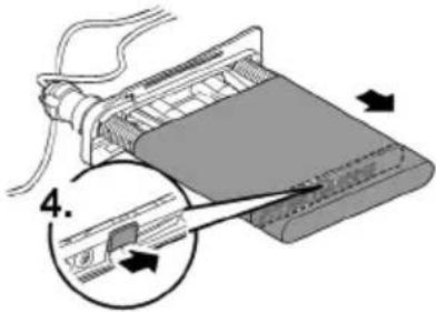
BTC0054
Uložení/zazimování
BTC0050
BTC0077
BTC0049
BTC0056
natural_image
Technical line drawing of an electronic device chassis with internal components and mounting holes (no text or symbols)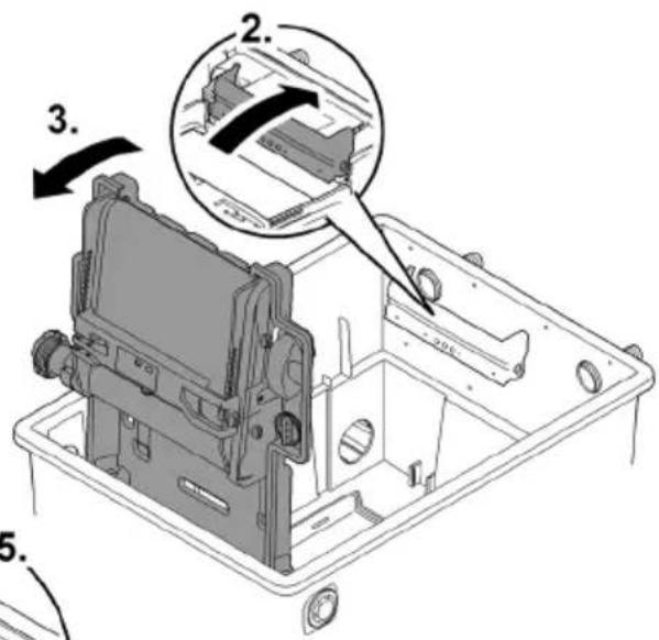

BTC0052

VÝSTRAHA
SK
8TC0061
natural_image
Technical line drawing of an electronic device casing with internal components and a handle (no text or symbols)
BTC0062
Obsluha
Ovládacie pole

flowchart
graph TD
    A["OK"] --> B["Cleaning"]
    B --> C["Check sensor"]
    C --> D["Clean screen"]
    style A fill:#f9f,stroke:#333
    style B fill:#ccf,stroke:#333
    style C fill:#cfc,stroke:#333
    style D fill:#fcc,stroke:#333
    subgraph Step 1
        E["1"] --> F["OK"]
        F --> G["Cleaning"]
        G --> H["Check sensor"]
        H --> I["Clean screen"]
    end
    subgraph Step 2
        J["2"] --> K["OK"]
        K --> L["Cleaning"]
        L --> M["Check sensor"]
        M --> N["Clean screen"]
    end
BTC0046
1 LED, 2-farebná
bar
| Category | Percentage (%) | | :--- | :--- | | Top Bar | 25 | | Middle Bar | 50 | | Bottom Bar | 75 | | Right Arrow | 100 | The diagram illustrates a step-by-step progression in the process: Step 1 (top bar) shows a single component, Step 2 (middle bar) shows a device component, and Step 3 (bottom bar) shows a machine tool or device with a base component. The visual emphasizes the relative proportions of each step.BTC0082
BioTec ScreenMatic ^2 145000
BTC0055
BioTec ScreenMatic2 90000
BTC008
SK
BioTec ScreenMatic ^2 145000
BTC008C
natural_image
Technical line drawing of an electronic device casing with internal components and directional arrows (no text or symbols)BioTec ScreenMatic ^2 40000, 60000, 90000
BioTec ScreenMatic ^2 145000

natural_image
Technical diagram of a mechanical assembly with no visible text or symbols
BTC006C
BTC0054
Uloženie/prezimovanie
BTC0050
BTC0077
BTC0049
BTC0056
Zagon
natural_image
Technical line drawing of an electronic device casing with internal components and a handle (no text or symbols)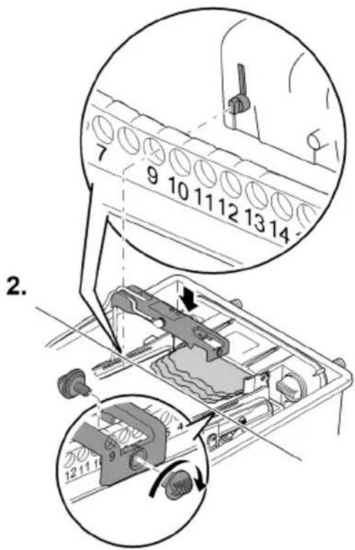
BTC0062
Upravljanje
Upravljalno polje
flowchart
graph TD
    A["OK"] --> B["Cleaning"]
    B --> C["Check sensor"]
    C --> D["Clean screen"]
    E["1"] --> F["2"]
    G["1x"] --> H["Circle icon"]
BTC0046
bar
| Category | Percentage (%) | | :--- | :--- | | Top Bar | 25 | | Middle Bar | 50 | | Bottom Bar | 75 | | Right Arrow | 100 | The diagram illustrates a step-by-step process: Step 1 (top bar) is labeled '1'. Step 2 (middle bar) is labeled '2'. Step 3 (bottom bar) is labeled '3'. The diagram includes three circular insets showing the process: Step 1 (top bar), Step 2 (middle bar), and Step 3 (bottom bar).BTC0082
BioTec ScreenMatic ^2 145000
BTC0055
BioTec ScreenMatic ^2 90000
BTC008
SL
BioTec ScreenMatic ^2 145000
BTC008C
Očistite/zamenjajte sito ScreenMatic
Predpogoj:
natural_image
Technical line drawing of an electronic device casing with internal components and directional arrows indicating movement (no text or symbols)BioTec ScreenMatic ^2 40000, 60000, 90000
BioTec ScreenMatic ^2 145000


natural_image
Technical diagram of a mechanical assembly with no visible text or symbols
BTC006C
Zamenjajte filtrirne pene
Predpogoj:
BTC0054
BTC0050
| 1 | Ulazi, dva komada |
| 2 | Razdjelnik vode |
| 3 | Produžetak razdjelnika |
| 4 | Četka, za redovito čišćenje ScreenMatic sita |
| 5 | Cijev za supstratBioTec ScreenMatic^2 40000: 2 komadaBioTec ScreenMatic^2 60000: 3 komada |
| 6 | Pregrada, odvojiva radi održavanja |
| 7 | Filtarska spužva, 8 komada |
| 8 | Čep, za zatvaranje izlaza (14)Prilikom čišćenja filtarskih spužava sa zatvorenim izlazom prljava voda neće teći natrag u je-zerce |
| 9 | Odvod prljavštine |
| 10 | Čistač spužve |
| 11 | Držač čistača spužve |
| 12 | Zasun odvoda prljavštine |
| 13 | Korito za prljavštinu |
| 14 | Izlaz |
BioTec ScreenMatic ^2 90000

BTC0077
| 1 | Ulazi, dva komada |
| 2 | Razdjelnik vode |
| 3 | Produžetak razdjelnika |
| 4 | Četka, za redovito čišćenje ScreenMatic sita |
| 5 | Cijev za supstrat, 4 komada |
| 6 | Pregrada, odvojiva radi održavanja |
| 7 | Filtarska spužva, 16 komada |
| 8 | Čep, za zatvaranje izlaza (14)Prilikom čišćenja filtarskih spužava sa zatvorenim izlazom prljava voda neće teći natrag u je-zerce |
| 9 | Odvod prljavštine |
| 10 | Čistač spužve |
| 11 | Držač čistača spužve |
| 12 | Zasun odvoda prljavštine |
| 13 | Korito za prljavštinu |
| 14 | Izlaz |
BioTec ScreenMatic ^2 145000
BTC0049
| 1 | Ulazi, dva komada |
| 2 | Razdjelnik vode |
| 3 | Produžetak razdjelnika |
| 4 | Četka, za redovito čišćenjeScreenMatic sita |
| 5 | Pregrada |
| 6 | Cijev za supstrat, 12 komada |
| 7 | Izlaz |
| 8 | Filtarska spužva, 18 komada |
| 9 | Čep, za zatvaranje izlaza (14)Prilikom čišćenja filtarskih spužava sa zatvorenim izlazom prljava voda neće teći natrag u je-zerce |
| 10 | Odvod prljavštine |
| 11 | Korito za prljavštinu |
| 12 | Čistač spužve |
ScreenMatic tračni sklop
BTC0056
| 1 | Upravljački sustav |
| 2 | Upravljačka ploča |
| 3 | Senzor na donjoj strani upravljačkog sustavaU slučaju kontakta senzora s vodom na ScreenMatic situ aktivirat će se automatsko čišćenje |
| 4 | StrugaloStruže prljavštinu sa ScreenMatic sita i transportira je u košaru za prljavštinu |
| 5 | ScreenMatic sito |
| 6 | Oznaka „Maks. razina vode“Prljavština se eventualno ispire iz košare za prljavštinu kada razina vode iz razdjelnika vode preko-rači oznaku |
| 7 | TransformerOpskrba elektroenergijom za upravljački sustav i motor |
| 8 | MotorPogon ScreenMatic tračnog sklopa |
Svojstva
- Visokoučinkovit protočni filtar za jezerca do 40 m ^3 , 60 m ^3 , 90 m ^3 ili 140 m ^3 .
- Električno ScreenMatic sito za automatsko razdvajanje grube prljavštine.
- Filtar ne zahtijeva veliko održavanje zbog razdvajanja grube prljavštine.
- Podni odvod sa zasunom za uklanjanje prljavštine iz filtarskog sustava.
- Ugodno čišćenje filtarskih spužava izravno u filtru.
- Čistač spužve i držač čistača spužve na spremniku.
- Optimalno prilagođeno OASE AquaMax Eco filtarskim crpkama.
- Mogućnost izravnog priključivanja OASE UVC pročistača serije Vitronic 18W/24W/36W, Bitron C i Bitron Eco.
- Uporaba raznih filtarskih medija radi optimalnog razvoja filtarske biologije.
Tehnički podatci
Podaci o uređaju
| BioTec ScreenMatic2 | 40000 | 60000 | 90000 | 145000 | ||
| Mrežni sklop | Nazivni napon primara | V AC | 230 | 230 | 230 | 230 |
| Frekvencija mreže | Hz | 50 | 50 | 50 | 50 | |
| Nazivni napon sekundara | V DC | 12 | 12 | 12 | 12 | |
| Dopuštena okolna tempe-ratura | °C | -10 ... +35 | -10 ... +35 | -10 ... +35 | -10 ... +35 | |
| Upravljački sus-tav | Primljena snaga | W | 5 | 5 | 5 | 5 |
| Dopuštena okolna tempe-ratura | °C | -10 ... +35 | -10 ... +35 | -10 ... +35 | -10 ... +35 | |
| Duljina kabela | Mrežni sklop | m | 2,10 | 2,10 | 2,10 | 2,10 |
| Upravljački sustav | m | 5,00 | 5,00 | 5,00 | 5,00 | |
| Filtarska spužva | Broj plavih | kom. | 2 | 2 | 4 | 4 |
| Broj crvenih | kom. | 3 | 3 | 6 | 7 | |
| Broj ljubičastih | kom. | 3 | 3 | 6 | 7 | |
| Specijalni filtarski granulat | kg | 2,50 | 3,50 | 5 | 14,50 | |
| Separiranje grube prljavštine | μm | 300 | 300 | 300 | 300 | |
| Dopuštena temperatura vode | °C | +4 ... +35 | +4 ... +35 | +4 ... +35 | +4 ... +35 | |
| Ulaz | Količina | kom. | 2 | 2 | 2 | 2 |
| Crijevni priključak | mm | 25, 32, 38 | 25, 32, 38 | 25, 32, 38, 50 | 25, 32, 38, 50 | |
| G1, G11⁄4, G11⁄2 | G1, G11⁄4, G11⁄2 | G1, G11⁄4, G11⁄2, G2 | G1, G11⁄4, G11⁄2, G2 | |||
| Priključak UVC pročišćivača | Bitron C 36 W /55 W / 72 W / 110 W Bitron Eco 120 W / 180 W / 240 W Vitronic 18 W / 24 W / 36 W | |||||
| Izlaz | Količina | kom. | 1 | 1 | 1 | 1 |
| Priključak | DN 75 | DN 75 | DN 110 | DN 110 | ||
| Izlaz za prljav-štinu | Količina | kom. | 1 | 1 | 1 | 1 |
| Priključak | DN 50 | DN 50 | DN 50 | DN 75 | ||
| Optočni kapaci-tet | Minimalno | l/h | 4000 | 6000 | 8000 | 8000 |
| Maksimalno | l/h | 9000 | 11000 | 12500 | 17500 | |
| Maksimalni vo-lumen jezerca | Bez ribljeg fonda | m3 | 40 | 60 | 90 | 140 |
| S ribljim fondom | m3 | 20 | 30 | 45 | 70 | |
| Sa šaranima koi | m3 | 10 | 15 | 22,5 | 35 | |
| Dimenzije | Duljina | mm | 788 | 788 | 788 | 1200 |
| Širina | mm | 590 | 590 | 590 | 800 | |
| Visina | mm | 454 | 554 | 654 | 760 | |
| Masa | Bez vode | kg | 20 | 25 | 30 | 115 |
BTC0061
HR
Puštanje u rad
① Skinite zaštitnu foliju s cijevi za supstrat i umetnite cijevi za supstrat u spremnik.
natural_image
Technical line drawing of an electronic device chassis with internal components and mounting holes (no text or symbols)
BTC0062
Rukovanje
Upravljačka ploča

flowchart
graph TD
    A["OK"] --> B["Cleaning"]
    B --> C["Check sensor"]
    C --> D["Clean screen"]
    E["1"] --> F["2"]
    G["1x"] --> H["Circle icon"]
BTC0046
bar
| Category | Percentage (%) | | :--- | :--- | | Top Bar | 25 | | Middle Bar | 50 | | Bottom Bar | 75 | | Right Arrow | 100 | The diagram illustrates a step-by-step process: (1) to (2), (3), and (4). The process begins at step 1, then transitions through steps 2 and 3, which are shown as circular arrows pointing to the final step. The bottom step is labeled '1'. The right arrow is labeled '2'. The bottom step is labeled '3'.BTC0082
BioTec ScreenMatic ^2 145000
BTC0055
BioTec ScreenMatic ^2 90000
BTC008
HR
BioTec ScreenMatic ^2 145000
BTC008C
Čišćenje/zamjena ScreenMatic sita
Preduvjet:
• Filtracijska crpka je isključena.
- Spremnik je otvoren. (→ Skidanje poklopca spremnika)
- Košara za prljavštinu je izvađena. (→ Rasklapanje i zaklapanje držača sita)
natural_image
Technical line drawing of an electronic device casing with internal components and directional arrows indicating movement (no text or symbols)BioTec ScreenMatic ^2 40000, 60000, 90000
BioTec ScreenMatic ^2 145000


natural_image
Technical diagram of a mechanical assembly with no visible text or symbols
BTC006C
HR
Zamjena filtarskih spužava
Preduvjet:
• Filtracijska crpka je isključena.
- Spremnik je otvoren. (→ Skidanje poklopca spremnika)
- Držač sita je zaklopljen. (→ Rasklapanje i zaklapanje držača sita)
BTC0054
BTC0050
BTC0077
BTC0049
BTC0056
BTC0061
RO
natural_image
Technical line drawing of an electronic device casing with internal components and mounting holes (no text or symbols)
BTC0062
Modalitatea de operare
Panou de operare

flowchart
graph TD
    A["OK"] --> B["Cleaning"]
    B --> C["Check sensor"]
    C --> D["Clean screen"]
    style A fill:#f9f,stroke:#333
    style B fill:#ccf,stroke:#333
    style C fill:#cfc,stroke:#333
    style D fill:#fcc,stroke:#333
BTC0046
1 LED, 2-culori
BTC0055
BioTec ScreenMatic2 90000
BTC008
RO
BioTec ScreenMatic ^2 145000
BTC008C
natural_image
Technical line drawing of an electronic device casing with internal components and directional arrows indicating movement (no text or symbols)BioTec ScreenMatic ^2 40000, 60000, 90000
BioTec ScreenMatic ^2 145000


natural_image
Mechanical assembly diagram showing a component with a 3D arrow indicating direction (no text or symbols present)
BTC006C
RO
BTC0054
BTC0050
BTC0077
BTC0049
BTC0056
1 Управление
natural_image
3D technical illustration of a mechanical component with mounting holes and a central base (no text or symbols)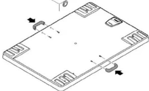
natural_image
Isometric technical drawing of a rectangular electronic component with mounting holes and internal slots (no text or symbols)BTC0051
BTC0061
natural_image
Technical line drawing of an electronic device casing with internal components and a labeled component (no text or symbols present)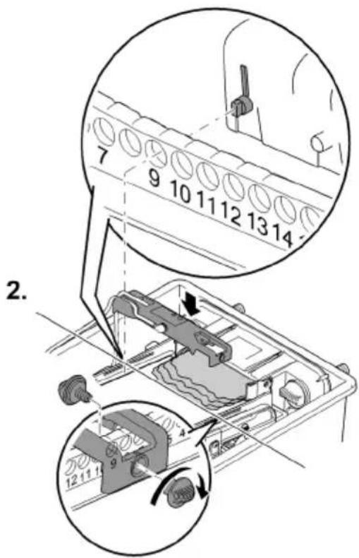
BTC0062
Обслужване
Панел за управление

flowchart
graph TD
    A["OK"] --> B["Cleaning"]
    B --> C["Check sensor"]
    C --> D["Clean screen"]
    E["1"] --> F["Step 1"]
    G["2"] --> H["Step 2"]
    I["1x"] --> J["Circle icon"]
BTC0046
1 LED, двуцветен
bar
| Category | Percentage (%) | | :--- | :--- | | Top Bar | 100 | | Bottom Bar | 50 | | Right Arrow (approx) | 25 | The diagram illustrates a step-by-step process: (1) Initial state, (2) Intermediate state, (3) Final state, and (4) Final state. The process is divided into three stages: (1) Initial state, (2) Intermediate state, and (3) Final state. Each stage includes a component icon (e.g., battery, fan, lamp).BTC0082
BioTec ScreenMatic ^2 145000
BTC0079
BTC0055
BioTec ScreenMatic ^2 90000
BTC0081
BG
BioTec ScreenMatic ^2 145000
BTC0080
natural_image
Technical line drawing of an electronic device casing with internal components and directional arrows indicating movement (no text or symbols)BioTec ScreenMatic ^2 40000, 60000, 90000
BioTec ScreenMatic ^2 145000


natural_image
Technical diagram of a mechanical assembly with no visible text or symbols
BTC0060
BTC0054
BTC0050
BTC0077
BTC0049
BTC0056
natural_image
Isometric diagram of a rectangular electronic device with mounting holes and a central component, showing no text or symbols.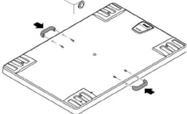
natural_image
Isometric line drawing of a rectangular electronic device with mounting holes and internal slots, showing no text or symbols.BTC0051
natural_image
Technical line drawing of a mechanical assembly with no visible text or symbols

BTC0052
UK
! УВАГА!
BTC0061
natural_image
Technical line drawing of a mechanical device interior (no text or symbols)
BTC0062
Обслуговування
Панель управління

flowchart
graph TD
    A["OK"] --> B["Cleaning"]
    B --> C["Check sensor"]
    C --> D["Clean screen"]
    E["1"] --> F["Step 1"]
    G["2"] --> H["Step 2"]
    I["Warning icon"] --> A
    J["Open icon"] --> E
    K["Circle icon"] --> H
BTC0046
bar
| Stage | Percentage (%) | |---|---| | Top Section | 25 | | Middle Section | 50 | | Bottom Section | 75 | | Right Section | 100 |BTC0053
BioTec ScreenMatic ^2 90000
bar
| Category | Percentage (%) | | :--- | :--- | | Top Bar | 100 | | Bottom Bar | 50 | | Right Arrow (approx) | 25 | The diagram illustrates a step-by-step process: (1) Initial state, (2) Intermediate state, (3) Final state, and (4) Final state. The process is divided into three stages: (1) Initial state, (2) Intermediate state, and (3) Final state. Each stage includes a component icon (e.g., battery, fan, lamp).BTC0082
BioTec ScreenMatic ^2 145000
BTC0055
BioTec ScreenMatic ^2 90000
BTC0081
UK
BioTec ScreenMatic ^2 145000
BTC0080
natural_image
Technical line drawing of an electronic device casing with internal components and directional arrows indicating movement (no text or symbols)BioTec ScreenMatic ^2 40000, 60000, 90000
BioTec ScreenMatic ^2 145000

natural_image
Mechanical assembly diagram showing a component with a 3D arrow indicating direction (no text or symbols present)
BTC0060
UK
BTC0054
BTC0050
BTC0077
BTC0049
BTC0056
1 Блок управления
2 Панель управления
natural_image
Isometric technical drawing of a rectangular electronic device with mounting feet and a side panel, showing no text or symbols.
natural_image
Isometric technical diagram of a rectangular electronic component with mounting holes and internal slots, showing directional arrows (no text or symbols)BTC0051
natural_image
Technical line drawing of an electronic device chassis with internal components and mounting holes (no text or symbols)
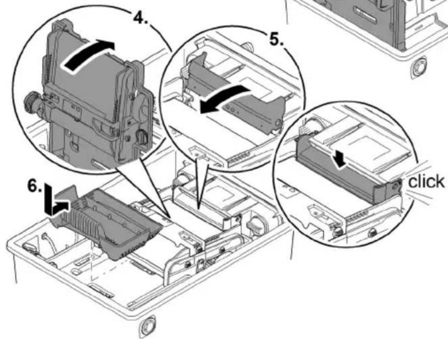
BTC0052
RU
ПРЕДУПРЕЖДЕНИЕ
BTC0061
Пуск в эксплуатацию
natural_image
Technical line drawing of a mechanical device casing with internal components and mounting holes (no text or symbols)
BTC0062
bar
| Step | Percentage (%) | |---|---| | Top Section | 25 | | Middle Section | 50 | | Bottom Section | 75 | | Right Section | 100 |BTC0053
BioTec ScreenMatic ^2 90000

bar
| Category | Percentage (%) | | :--- | :--- | | Top Bar | 100 | | Bottom Bar | 50 | | Right Arrow (approx) | 25 | The diagram illustrates a step-by-step process with three labeled steps: Step 1 (top-right), Step 2 (middle-left), and Step 3 (bottom-right). The top bar is visually scaled to 100% and the bottom bar to 25%. The diagram includes icons of a device, a computer monitor, and a hand tool, suggesting a process flow or manufacturing workflow.BTC0082
BioTec ScreenMatic ^2 145000
BTC0055
BioTec ScreenMatic ^2 90000
BTC0081
RU
BioTec ScreenMatic ^2 145000
BTC0080
natural_image
Technical line drawing of an electronic device casing with internal components and directional arrows indicating movement (no text or symbols)BioTec ScreenMatic ^2 40000, 60000, 90000
BioTec ScreenMatic ^2 145000


natural_image
Technical diagram of a mechanical assembly with no visible text or symbols
BTC0060
RU
BTC0054
BTC0050
BTC0077
BTC0049
1 输入口,两个
2 配水器
3 分配器延长件
BTC0056
1 控制器
2 操作面板
3 控制器背面上的传感器
BTC0052
警告
电击可导致重伤或死亡。
游泳池的保护措施:
BTC0061
投入使用
BTC0062
操作
操作面板

flowchart
graph TD
    A["OK"] --> B["Cleaning"]
    B --> C["Check sensor"]
    C --> D["Clean screen"]
    E["1"] --> F["2"]
    G["1x"] --> H["Circle icon"]
BTC0046
1 2 色 LED
bar
| Category | Percentage (%) | | :--- | :--- | | Top Bar | 100 | | Bottom Bar | 50 | | Right Arrow | ≈ | | Step | Description | | :--- | Description | | 1 | Top Bar (approx. 25%) | | 2 | Top Bar (approx. 75%) | | 3 | Bottom Bar (approx. 30%) |BTC0082
ZH
步骤如下:
BTC0055
BioTec ScreenMatic ^2 90000
步骤如下:
BTC0081
BioTec ScreenMatic ^2 145000
步骤如下:
BTC0080
清洁/更换 ScreenMatic 滤网
前提:
natural_image
Technical line drawing of an electronic device casing with internal components and directional arrows indicating movement (no text or symbols)BioTec ScreenMatic ^2 40000, 60000, 90000
BioTec ScreenMatic ^2 145000


natural_image
Technical diagram of a mechanical assembly with no visible text or symbols
BTC0060
更换过滤海绵
前提:
BTC0054
存放/过冬
BTC004C
| 1 | 45320 | 6 | 25507 | 10 | 25624 | 15 | 44343 |
| 3 | 42346 | 7 | 42341 | 11 | 43106 | 38 | 44308 |
| 4 | 42449 | 8 | 84923 | 12 | 44181 | ||
| 5 | 42344 | 9 | 34830 | 13 | 34734 |
BioTec ScreenMatic ^2 40000, 60000
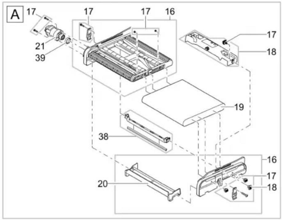
BTC0041
| 16 | 42383 | 18 | 44184 | 21 | 44183 | 39 | 42450 |
| 17 | 44178 | 20 | 44177 | 38 | 44308 |
BioTec ScreenMatic ^2 40000, 60000

BTC0043
| 22 | 48674 | 24 | 19506 | 26 | 25691 | 28 | 44179 |
| 23 | 43749 | 25 | 44337 | 27 | 42949 | 29 | 25000 |
BioTec ScreenMatic ^2 40000, 60000
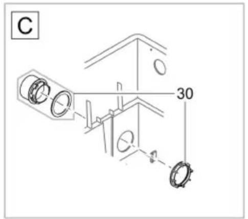
30 45321
31 44182
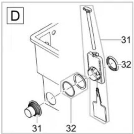
BTC0044
32 34859
BTC0045
BioTec ScreenMatic ^2 40000, 60000
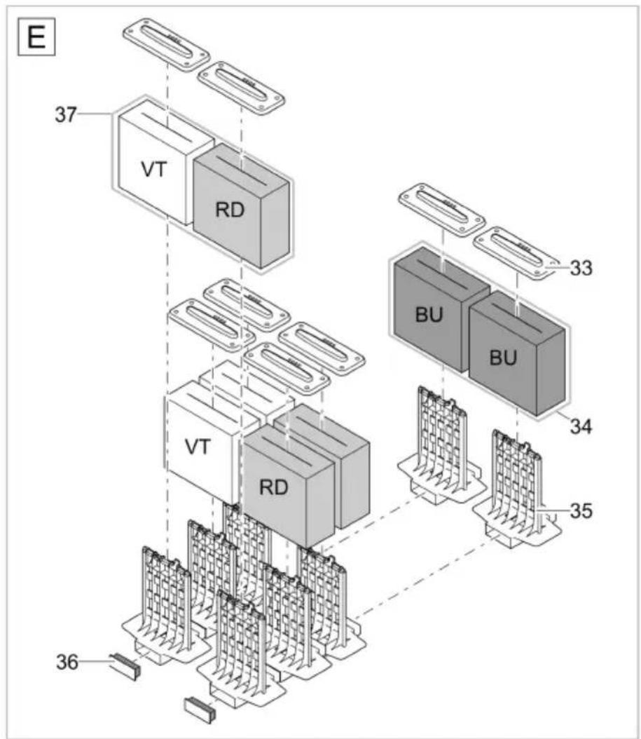
BTC0042
BioTec ScreenMatic ^2 40000
BioTec ScreenMatic ^2 60000
| 33 | 34670 | 36 | 25524 | 33 | 34670 | 36 | 25524 |
| 34 | 42895 | 37 | 42893 | 34 | 42896 | 37 | 42894 |
| 35 | 26305 | 35 | 34733 |
BioTec ScreenMatic ^2 90000
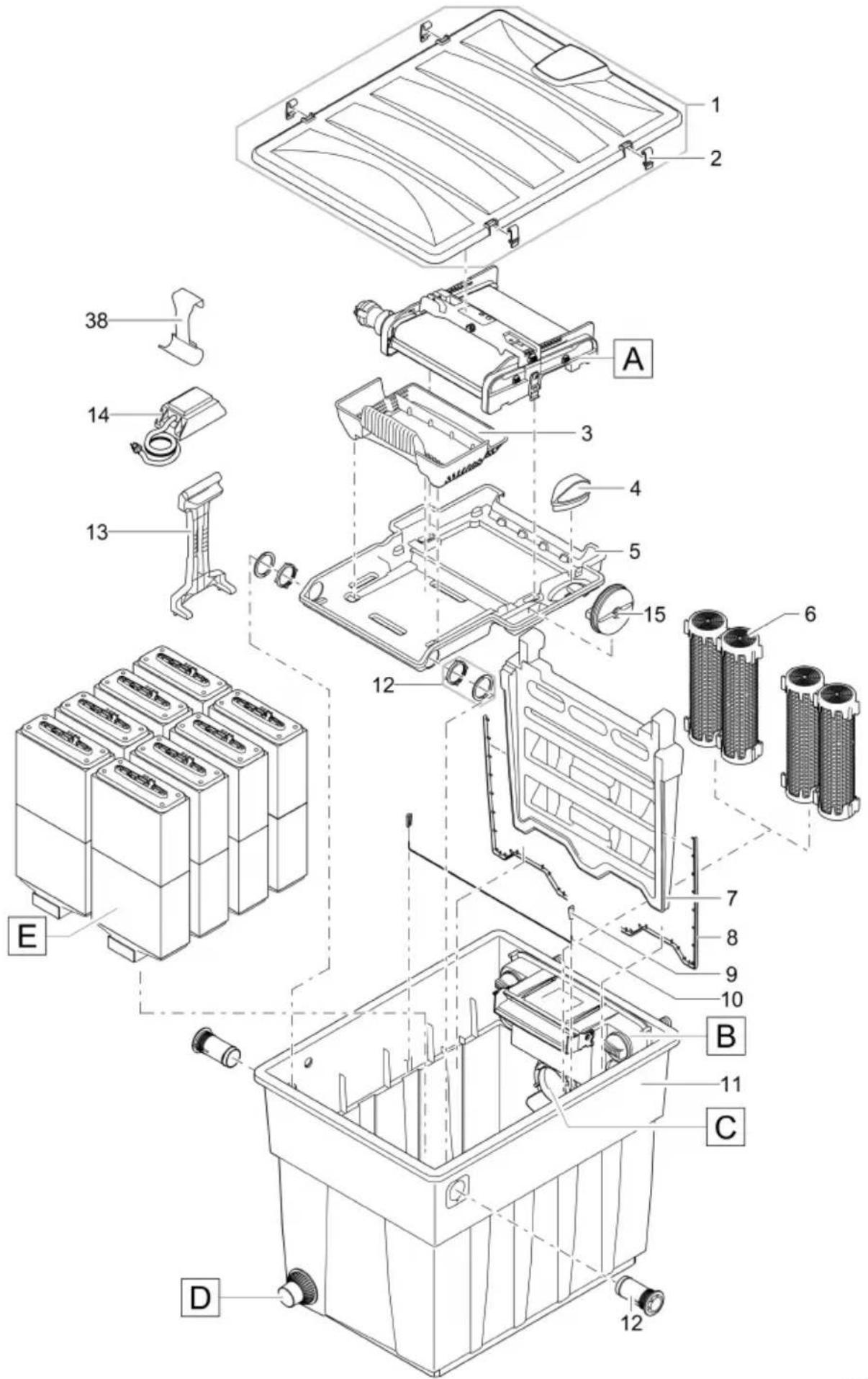
BTC0078
| 1 | 45320 | 6 | 25507 | 10 | 25646 | 15 | 44173 |
| 3 | 42346 | 7 | 42342 | 11 | 49600 | 38 | 44308 |
| 4 | 42449 | 8 | 47031 | 12 | 44181 | ||
| 5 | 45323 | 9 | 34830 | 13 | 45252 |
BioTec ScreenMatic ^2 90000

BTC0041
| 16 | 42383 | 18 | 44184 | 21 | 44183 | 39 | 42450 |
| 17 | 44178 | 20 | 44177 | 38 | 44308 |
BioTec ScreenMatic ^2 90000
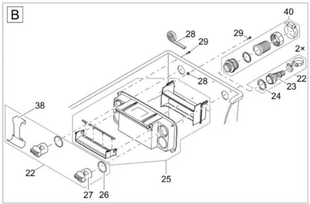
BTC0086
| 16 | 42383 | 20 | 44177 | 24 | 19506 | 28 | 44179 |
| 17 | 44178 | 21 | 44183 | 25 | 44337 | 29 | 25000 |
| 18 | 44184 | 22 | 48674 | 26 | 25691 | 38 | 44308 |
| 19 | 42325 | 23 | 43749 | 27 | 42949 | 40 | 34367 |
BioTec ScreenMatic ^2 90000
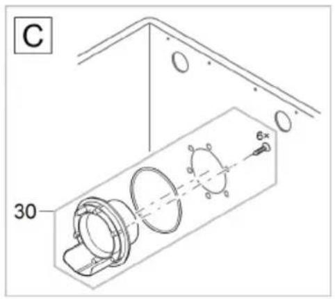
30 48686
31 44182
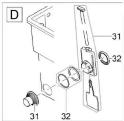
BTC0084
32 34859
BTC0085
BioTec ScreenMatic ^2 90000
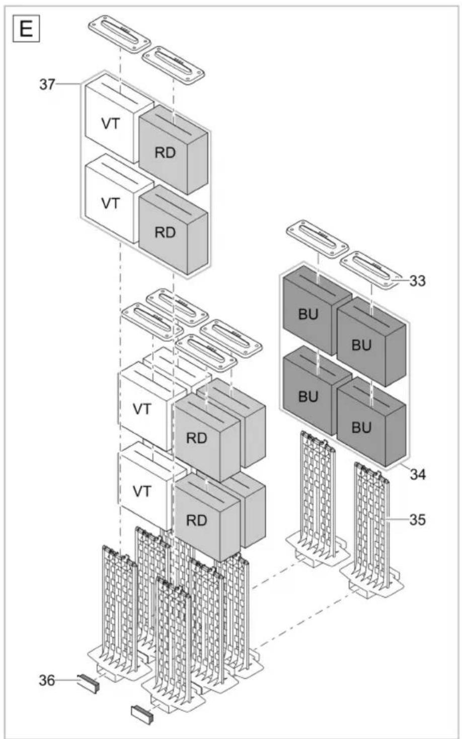
BTC0083
33 34670
35 45254
37 42893
34 42895
36 45325
BioTec ScreenMatic ^2 145000
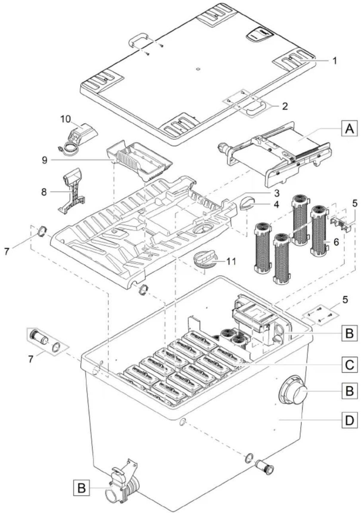
BTC0112
| 1 | 73381 | 4 | 42449 | 7 | 44181 | 10 | 15118 |
| 2 | 93094 | 5 | 34864 | 8 | 45252 | 11 | 44173 |
| 3 | 42345 | 6 | 25507 | 9 | 42346 |
BioTec ScreenMatic ^2 145000
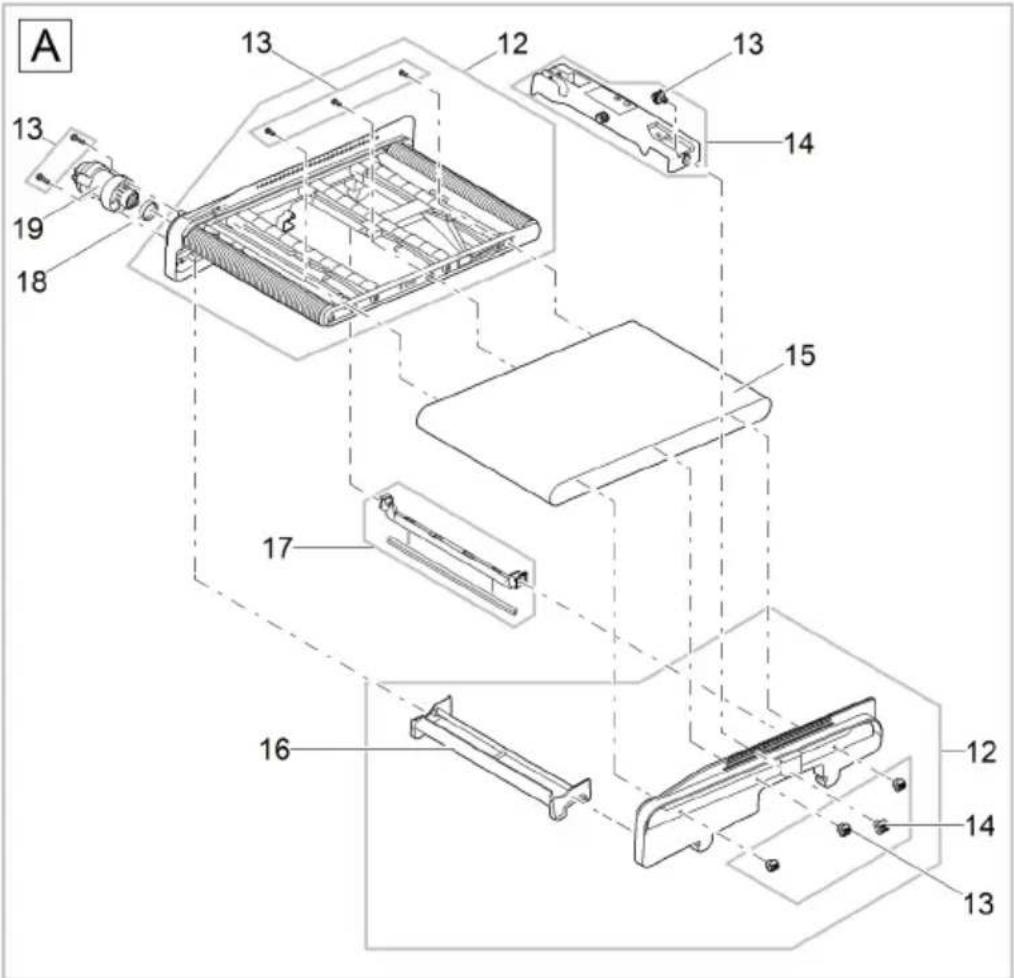
BTC0113
| 12 | 42384 | 14 | 44186 | 16 | 44177 | 18 | 42450 |
| 13 | 44178 | 15 | 42326 | 17 | 44308 | 19 | 44183 |
BioTec ScreenMatic ^2 145000
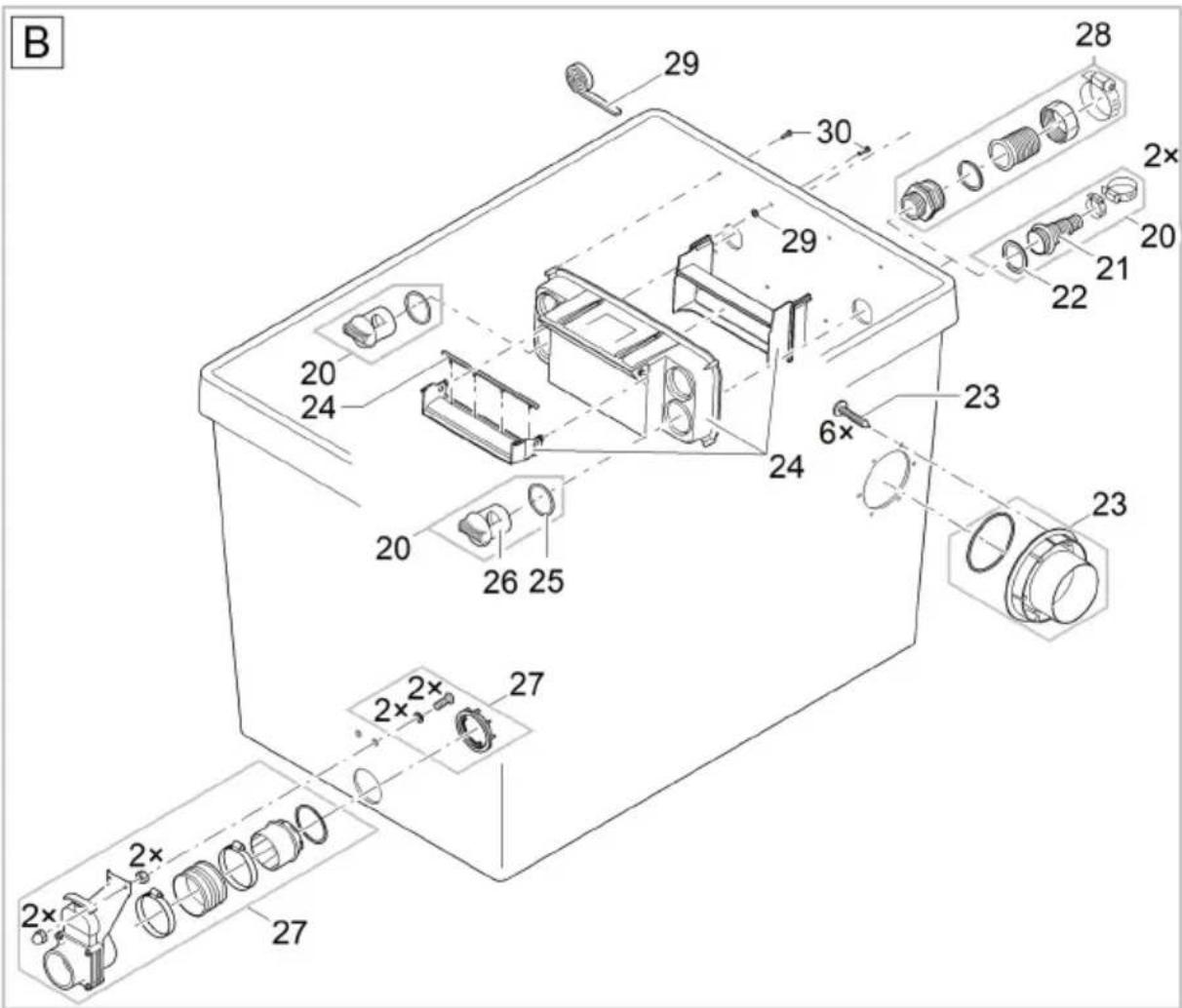
BTC0114
| 20 | 48674 | 23 | 77507 | 26 | 42949 | 29 | 44179 |
| 21 | 43749 | 24 | 44338 | 27 | 70636 | 30 | 34784 |
| 22 | 19506 | 25 | 25691 | 28 | 34367 |
BioTec ScreenMatic ^2 145000
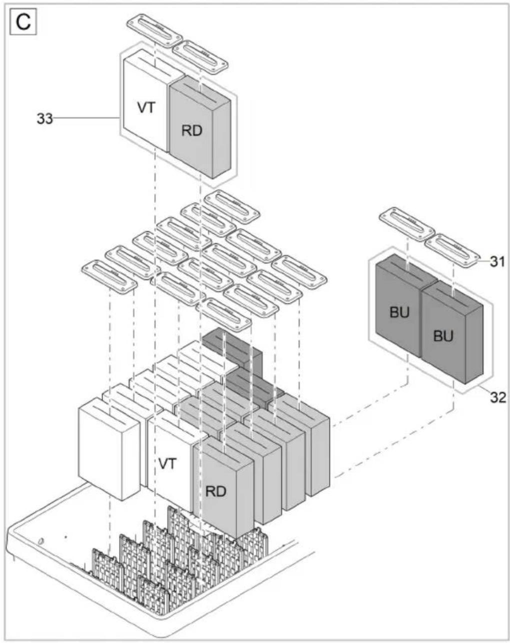
31 34670
32 42896
33 42894
BTC0115
BioTec ScreenMatic ^2 145000
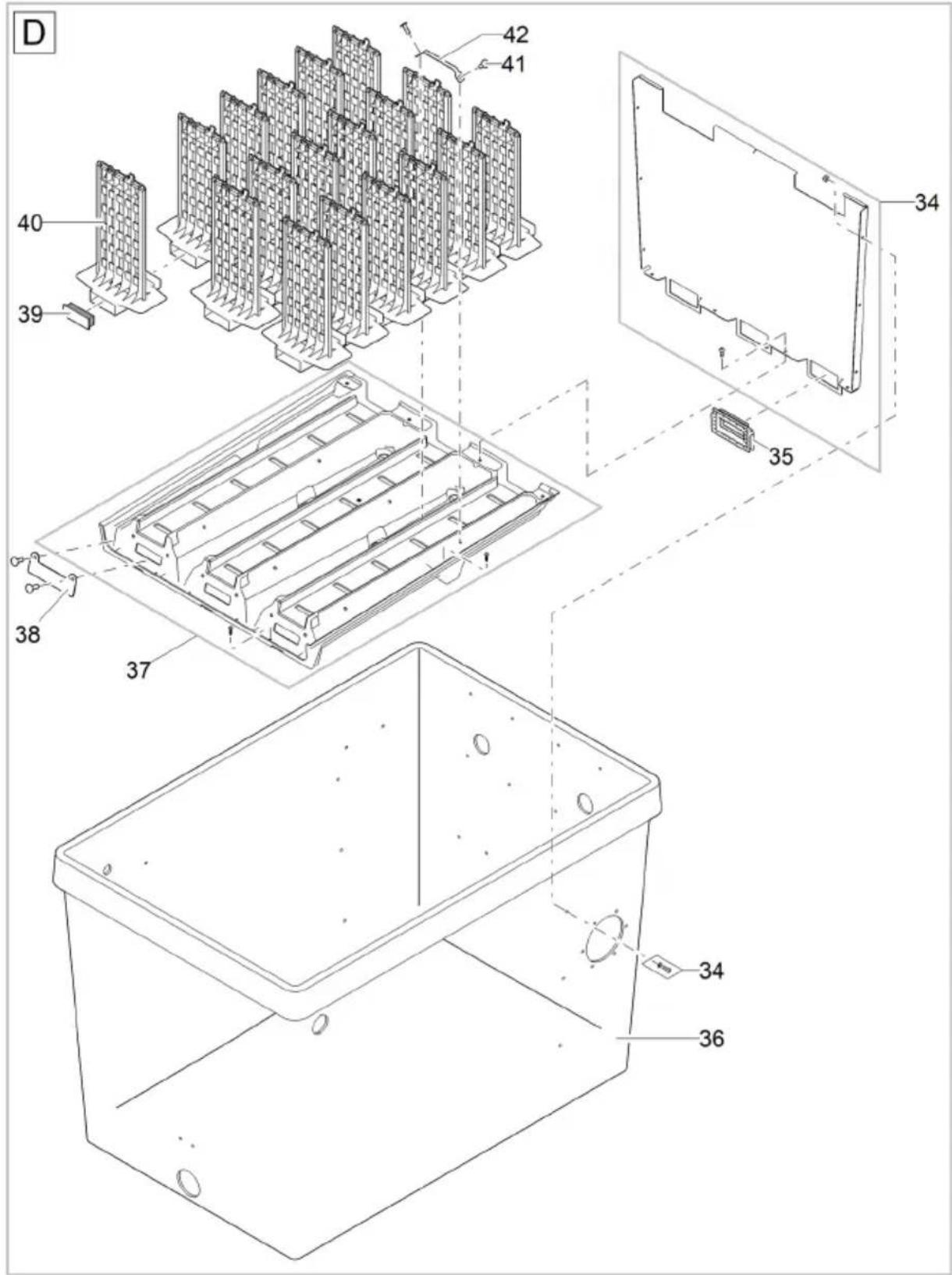
BTC0116
| 34 | 93460 | 37 | 93461 | 40 | 34733 |
| 35 | 93101 | 38 | 25547 | 41 | 25546 |
| 36 | 93103 | 39 | 45325 | 42 | 25922 |
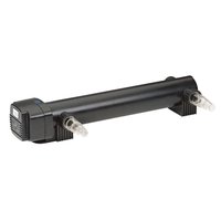
- BioTec ScreenMatic 2
- WARNING
- BioTec ScreenMatic 2 145000
- So gehen Sie vor:
- BioTec ScreenMatic 2 90000
- Lagern/Überwintern
- Safety information
- Electrical connection
- Safe operation
- Intended use
- Product Description
- Unit configuration
- ScreenMatic rotating screen unit
- Properties
- Installation and connection
- Access to the device
- Remove the container cover
- Hinging the screen holder up/down
- Inlets
- Connecting the filter pump
- Connecting a UVC clarifier
- Fitting the outlet
- Prerequisite:
- How to proceed:
- Outlets
- Installing the dirt outlet
- Connecting the dirt outlet
- Carry out the electrical connection
- Commissioning/start-up
- Biological filter starter
- Order of starting up steps
- Aligning the control device
- Do not align the control device until after the running-in period
- Aligning the control device depending on the degree of soiling of the pond
- Typical position of the control device
- Operation
- Operating panel
- Manual cleaning
- Automatic cleaning
- Time-dependent cleaning
- Maintenance and cleaning
- Regular cleaning work
- Cleaning foam filters
- BioTec ScreenMatic 2 40000, 60000, 90000
- Cleaning/replacing the substrate tubes
- BioTec ScreenMatic 2 40000, 60000
- Cleaning/replacing the ScreenMatic screen
- Replacing foam filters
- Storage/winter protection
- The unit is protected from frost (e.g. stored in a garage or other enclosure)
- The unit is not protected from frost (e.g. outdoor installation)
- Wear parts
- Disposal
- NOTE
- AVERTISSEMENT
- Mise en service
- Utilisation
- Tableau de commande
- Nettoyage/Remplacement de la crépine-ScreenMatic
- Ingebruikname
- Bediening
- Bedieningspaneel
- Zo gaat u te werk:
- ScreenMatic-zeef reinigen/vervangen
- Filtersponzen vervangen
- Opslag/overwinteren
- Puesta en marcha
- Operación
- Panel de control
- BioTec ScreenMatic2 90000
- Operação
- Painel de controlo
- Limpar/substituir o crivo ScreenMatic
- Substituir os filtros de espuma
- Armazenar/Invernar
- Messa in funzione
- Impiego
- Quadro comando
- Ibrugtagning
- Betjening
- Betjeningsfelt
- Sådan gør du:
- Udskift filterskum
- Forudsætning:
- Opbevaring/overvintring
- Apparatet står beskyttet mod frost (f.eks. i en garage eller carport)
- Igangsetting
- Bruk
- Manuell rengjøring
- Rengjøre/skifte ScreenMatic-filter
- Skifte skumfilter
- Forutsetning:
- Lagring/overvintring
- Apparatet står beskyttet mot frost (f.eks. i en garasje eller i en innhengning)
- Driftstart
- Manuell rengöring
- Rengör/byt ut ScreenMatic-silen
- Byta ut filtersvamparna
- Förutsättning:
- Käyttöönotto
- Käyttö
- Käyttökenttä
- FIGYELMEZTETÉS
- Üzembe helyezés
- Kezelés
- Kezelőmező
- Tárolás/Telelés
- Uruchomienie
- Obstuga
- Panel obstugowy
- Uvedení do provozu
- Uložení/zazimování
- VÝSTRAHA
- Obsluha
- Ovládacie pole
- Uloženie/prezimovanie
- Zagon
- Upravljanje
- Upravljalno polje
- Očistite/zamenjajte sito ScreenMatic
- Zamenjajte filtrirne pene
- Predpogoj:
- ScreenMatic tračni sklop
- Svojstva
- Puštanje u rad
- Rukovanje
- Upravljačka ploča
- Čišćenje/zamjena ScreenMatic sita
- Zamjena filtarskih spužava
- Preduvjet:
- Modalitatea de operare
- Panou de operare
- Обслужване
- Панел за управление
- ! УВАГА!
- Обслуговування
- Панель управління
- ПРЕДУПРЕЖДЕНИЕ
- Пуск в эксплуатацию
- 警告
- 投入使用
- 操作
- 操作面板
- 步骤如下:
- 清洁/更换 ScreenMatic 滤网
- 更换过滤海绵
- 前提:
- 存放/过冬
Brand : OASE
Model : BioTec ScreenMatic 60000
Category : Water filter