
ProfiClear Premium TF-XL - Water filter OASE - Free user manual and instructions
Find the device manual for free ProfiClear Premium TF-XL OASE in PDF.

| Product Type | Drum filter for garden pond |
| Brand | Oase |
| Model | ProfiClear Premium TF-XL EGC |
| Use | Mechanical filtration of pond water (coarse particles) |
| Dimensions (L x W x H) | 1295 x 861 x 821 mm |
| Empty weight | 125 kg |
| Operating weight | 535 kg (pumped version) / 655 kg (gravity version) |
| Rated voltage | 230 V / 50 Hz |
| Power consumption | 5 W (rest), 1100 W (cleaning), 1600 W max |
| Permissible water temperature | +4 °C to +35 °C |
| Max recirculation flow rate | 50,000 l/h (pumped) / 66,000 l/h (gravity) |
| Filtration fineness | 60 µm (standard screen, optional 150 µm) |
| Number of screen elements | 16 |
| Total screen area | Not specified |
| Flushing pump | Pressure 7 bar, water consumption 3.2 L per cycle |
| Cleaning | Automatic (level detection) + manual + programmed |
| Control system | Easy Garden Control (EGC) with display, smartphone compatible |
| Electrical protection | Residual current circuit breaker 30 mA recommended, fuse 16 A |
| Protection rating | Control: IP54 (water splashes), drum motor: waterproof |
| Container material | UV-resistant polyethylene (PE) |
| Wear parts | Screen elements, fuse, drum seal, pump capacitor |
| Maintenance | Monthly cleaning of the bottom, descaling of screens every 2-3 months |
| Warranty | 2 years (extendable with OASE registration) |
| Compatible accessories | Bitron Premium UVC clarifier, AquaMax Eco pumps, Moving Bed module |
Frequently Asked Questions - ProfiClear Premium TF-XL OASE
User questions about ProfiClear Premium TF-XL OASE
0 question about this device. Answer the ones you know or ask your own.
Ask a new question about this device
Download the instructions for your Water filter in PDF format for free! Find your manual ProfiClear Premium TF-XL - OASE and take your electronic device back in hand. On this page are published all the documents necessary for the use of your device. ProfiClear Premium TF-XL by OASE.
USER MANUAL ProfiClear Premium TF-XL OASE
natural_image
Black-and-white close-up of two koi fish swimming in dark water, no text or symbols visibleProfiClear Premium TF-XL
EN Operating instructions
FR Notice d'emploi
natural_image
Close-up of a black plastic grid panel inside a vehicle or industrial enclosure (no visible text or symbols)ProfiClear Premium TF-XL Pumped
Proficlear0224
ProfiClear Premium TF-XL Gravity
ProfiClear0225
B

ProfiClear0199

E
ProfiClear0214
F
ProfiClear0217
G
ProfiClear0216
H
ProfiClear0227
J
natural_image
Cross-sectional diagram of a water treatment or irrigation system with pipes, valves, and a central container (no text or labels)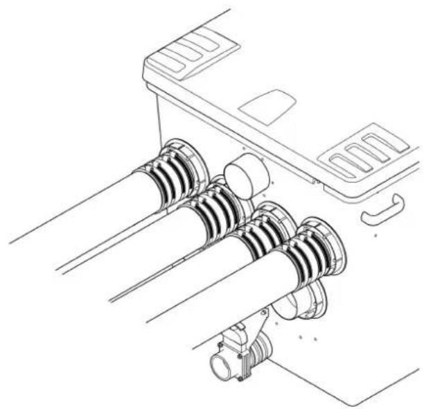
natural_image
Technical line drawing of a mechanical assembly with coiled components and mounting bracket (no text or symbols)ProfiClear0228
K
natural_image
Technical line drawing of a device with labeled connectors and ports (no text or symbols)Prof:Clear0201
natural_image
Line drawing of a portable air purifier connected to a cable, with no text or symbols present.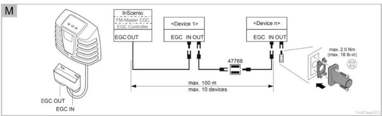
flowchart
graph TD
    A["ECG OUT"] --> B["EGC IN"]
    B --> C["InScenio FM-Master EGC EGC Controller"]
    C --> D["EGC OUT"]
    D --> E["47788 Device"]
    E --> F["EGC IN OUT"]
    F --> G["<Device 1>"]
    G --> H["EGC IN OUT"]
    H --> I["<Device n>"]
    I --> J["EGC IN OUT"]
    J --> K["max. 2.0 Nm (max. 18 lb-in)"]
    style A fill:#f9f,stroke:#333
    style K fill:#ccf,stroke:#333

natural_image
Technical line drawing of a medical or laboratory device with a magnified inset showing internal components (no text or symbols)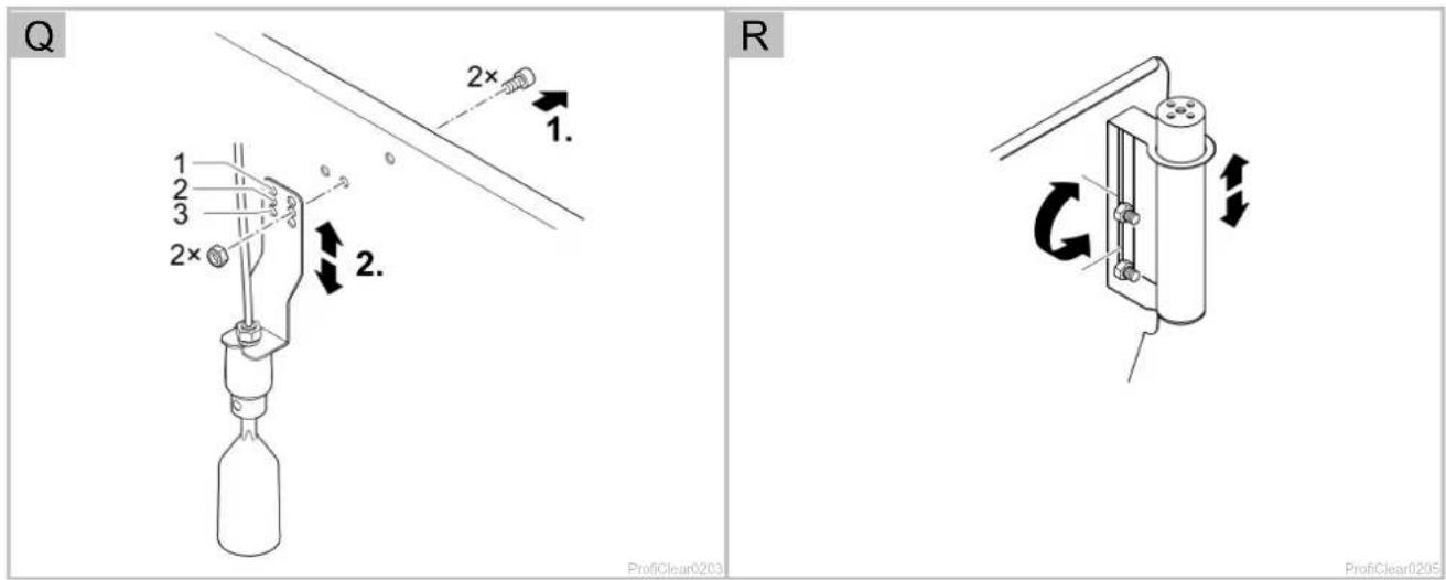
T
Prof|Clear0206
U
ProfiClear0210
W
Translation of the original Operating Instructions

WARNING
- This unit can be used by children aged 8 and above and by persons with reduced physical, sensory or mental capabilities or lack of experience and knowledge if they are supervised or have been instructed on how to use the unit in a safe way and they understand the hazards involved. Do not allow children to play with the unit. Only allow children to carry out cleaning and user maintenance under supervision.
- Ensure that the unit is fused for a rated fault current of max. 30 mA by means of a fault current protection device.
- Only connect the unit if the electrical data of the unit and the power supply correspond. The unit data is to be found on the unit type plate, on the packaging or in this manual.
- Disconnect all electrical devices in the water from the power supply before reaching into the water. Otherwise there is a risk of severe injuries or death by electrocution.
- A damaged connection cable cannot be replaced. Dispose of the unit.
Table of Contents
1 Information about these operating instructions....55
1.1 Warnings used in these instructions 55
1.2 Cross-references used in these instructions.... 55
2 Safety information 56
2.1 Electrical connection....56
2.2 Danger for persons with pacemakers....56
2.3 Safe operation....56
3 Product Description....57
3.1 Scope of delivery 57
3.2 Unit configuration 57
3.3 Function description....59
3.3.1 Pump fed system....59
3.3.2 Gravity fed system....59
3.4 Easy Garden Control System (EGC) 59
3.5 Intended use 60
4 Installation and connection....60
4.1 Fitting the filter container....60
4.1.1 Pump-fed system....61
4.1.2 Gravity fed system....62
4.2 Connecting the drum filter....62
4.2.1 Information regarding pipes....62
4.2.2 Connecting the inlet of the pump-fed system 63
4.2.3 Connecting the inlet of the gravity-fed system 63
4.2.4 Connecting the dirt outlet....63
4.3 Connecting the control system 64
4.4 Connecting the power pack 64
4.4.1 Connecting the EGC box....64
4.5 Installing the control system with EGC box 65
4.5.1 Pump fed system....65
4.5.2 Gravity fed system....65
5 Commissioning/start-up 65
5.1 Pump-fed system 66
5.1.1 Order of starting up steps....66
5.1.2 Setting the level detection device....67
5.2 Gravity-fed system 67
5.2.1 Order of starting up steps 67
5.2.2 Setting the level detection device 68
5.2.3 Setting the filter pump status detection 68
6 Operation....70
6.1 Control system overview....70
6.2 Switching ON/OFF 70
6.3 Operating modes 71
6.4 Manual cleaning....71
6.5 Settings in the menus 71
6.5.1 CL: Cleaning time "Cleaning" 71
6.5.2 In: Time-dependent cleaning "Interval" 72
6.5.3 EC: Extended cleaning time "Extra Cleaning" 72
6.5.4 IE: Interval of the extended cleaning time "Interval Extra Cleaning" 73
6.5.5 E7: Pump status detection 73
6.6 Reading out the number of cleaning cycles....74
6.6.1 Cleaning cycles in 24 hours....74
6.6.2 Total cleaning cycles 74
6.7 Loading default settings 74
6.8 System messages....75
7 Malfunction remedy....78
8 Maintenance and cleaning 79
8.1 Cleaning the device....79
8.2 Regular tasks 79
8.3 Cleaning the entire filter system....80
8.4 Cleaning the rinsing device....80
8.5 Cleaning the screen elements 80
8.5.1 Removing the screen element....80
8.5.2 Decalcifying the screen elements....81
8.6 Removing the filter drum....81
8.7 Installing the filter drum....81
8.8 Cleaning the rinsing pump 82
8.9 Replacing the rinsing pump 82
9 Storage/winter protection 82
10 Wear parts....83
11 Disposal....83
12 Spare parts....83
13 Technical data....83
14 Symbols on the unit....85
1 Information about these operating instructions
You made a good choice with the purchase of this product ProfiClear Premium TF-XL EGC.
Prior to commissioning the unit, please read the instructions of use carefully and fully familiarise yourself with the unit. Ensure that all work on and with this unit is only carried out in accordance with these instructions.
Adhere to the safety information for the correct and safe use of the unit.
Keep these instructions in a safe place! Please also hand over the instructions when passing the unit on to a new owner.
1.1 Warnings used in these instructions
The warning information is categorised by signal words, which indicate the extent of the hazard.

WARNING
Indicates a possibly dangerous situation, which could lead to death or severe injuries, if not avoided.

NOTE
Indicates a possibly dangerous situation, which could lead to damage to property or the environment, if not avoided.

TIP
Useful tip.
1.2 Cross-references used in these instructions
☐ A reference to a figure, e. g. figure A.
→ Reference to another section.
2 Safety information
2.1 Electrical connection
- Electrical installations must meet the national regulations and may only be carried out by a qualified electrician.
- A person is regarded as a qualified electrician if, due to his/her vocational education, knowledge and experience, he or she is capable of and authorised to judge and carry out the work commissioned to him/her. This also includes the recognition of possible hazards and the adherence to the pertinent regional and national standards, rules and regulations.
- For your own safety, please consult a qualified electrician.
- Switch off all units in the aquarium or disconnect the power plugs of all units before reaching into the water.
- Only connect the unit to a correctly fitted socket.
- Extension cables and power distributors (e.g. outlet strips) must be suitable for outdoor use (splash-proof).
- Protect the plug connection from moisture.
2.2 Danger for persons with pacemakers
- The container cover contains a magnet with a strong magnetic field that may affect the operation of pacemakers or implantable cardioverter defibrillators (ICDs). Always keep magnets at least 20 cm away from implanted devices.
2.3 Safe operation
- Never operate the unit if the housing is defective!
- Never operate the unit if an electrical cable is defective!
- Never carry or pull the unit by the electrical cable.
- Route cables such that they are protected from damage and do not present a tripping hazard.
• Never carry out technical changes to the unit. - Only carry out work on the unit that is described in this manual. If problems cannot be overcome, please contact an authorised customer service point or, if in doubt, the manufacturer.
- Only use original spare parts and accessories for the unit.
- Disconnect the unit from the power supply during thunderstorms.
- Overvoltage in the mains could lead to operating malfunctions of the unit. For information, please refer to chapter "Remedy of faults".
- Do not breath in the spray from the rinsing device. The spray may contain harmful bacteria. When the container cover is lifted up, the rinsing device continues operating.
3 Product Description
The following modules are available for the OASE filter system ProfiClear Premium XL:
• ProfiClear Premium TF-XL pumped EGC
• ProfiClear Premium TF-XL gravitation EGC
• ProfiClear Premium XL Moving Bed module
• ProfiClear Premium XL Discharge module, pumped
• ProfiClear Premium XL Discharge module, gravitation
3.1 Scope of delivery
| ProfiClear Premium TF-XL | Description | |||
| ☐ A | pump-fed | ☐ B | gravity-fed | |
| 1 x | 1 x | Filter drum | ||
| 1 x | 1 x | Control system with EGC box | ||
| 1 x | 1 x | Power pack | ||
| 2 x | 2 x | Cap, cap nut for fixing the EGC box when mounting it on the con-tainer wall | ||
| 5 x | 5 x | 6 × 12 × 1 mm fibre disc as a spare (expansion seal) | ||
| - | 2 x | Ground stake for installing the control system with EGC box | ||
| 2 x | - | Fastening bracket for Bitron Premium 60 W / 120 W / 180 W | ||
| 1 x | - | Connection set2× rubber sleeve DN110 / DN 1108× hose clip 110 ... 130 mm2× BG pipe connection Optimax2× hose connector G2 with thread3× hose connector G23× union nut G23× flat gasket 57 × 48 × 35× hose clip 40 ... 60 mm | ||
| 1 x | 1 x | Set of accessories1× Seal of Quality booklet1× Warranty booklet1× OASE clear water guarantee card1× Warranty extension booklet1× Turmsilon GTI 300 GK tube 10 ml1× CE declaration OASE pumps1× EGC 2017 flyer | ||
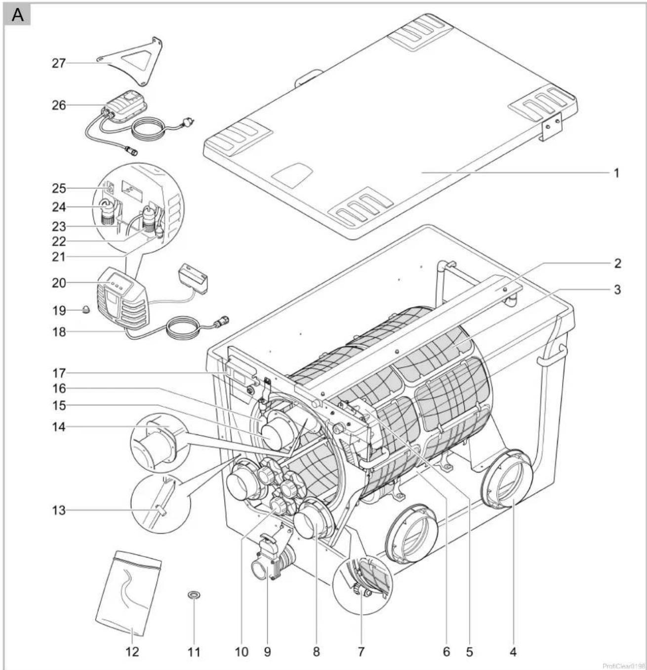
3.2 Unit configuration
| ProfiClear Premium TF-XL | Description | |||
| ☐ A | pump-fed | ☐ B | gravity-fed | |
| 1 | 1 | Container cover | ||
| 2 | 2 | Rinsing device• sprays water at high pressure onto the screen elements (3) to rinse off the coarse dirt | ||
| 3 | 3 | Filter drum with 16 screen elements• screen elements for coarse dirt down to 60 μm in size (also optionally available with 150 μm) | ||
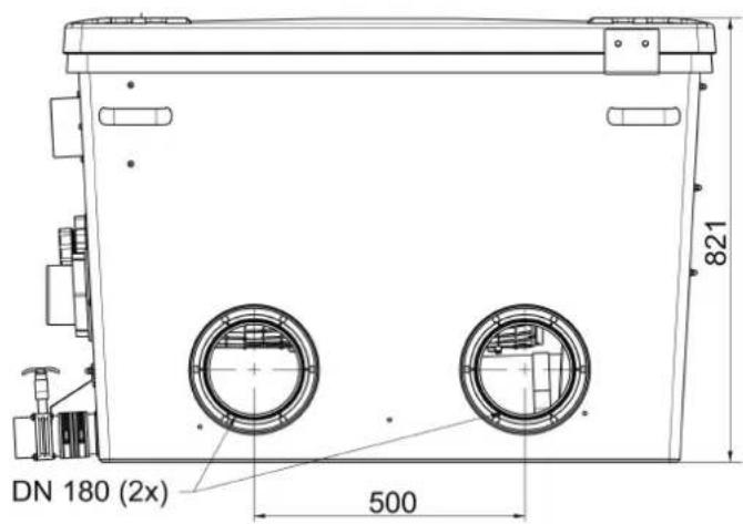
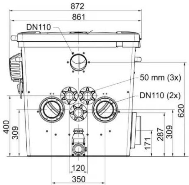
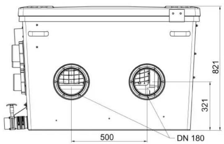
| 4 | 4 | 2× DN 180 outlet | ||
| 5 | 5 | Drum motor for filter drum (3)• The motor is connected to the control system (21) | ||
| 6 | 6 | Rinsing pump• for supplying the rinsing device (2) | ||
| 7 | 7 | Rollers• for guiding the filter drum | ||
| 8 | 8 | DN 110 inlet | ||
| • ProfiClear Premium TF-XL gepumpt EGC: 2× inlet• ProfiClear Premium TF-XL Gravitation EGC: 7× inlet | ||||
| 9 | 9 | DN 75 dirt outlet with slide valve | ||
| 10 | - | 3× 50 mm (G2) connection for connecting filter pumps with internal non-return valves | ||
| 11 | 11 | 5× fibre disc 6 × 12 × 1 mm as replacement (expansion seal) | ||
| 12 | - | Connection set for connecting filter pumps• For connection to 50 mm (G2) connections (10) | ||
| 13 | 13 | • Temperature probe• monitors the water temperature | ||
| 14 | 14 | Dirt channel• collects the coarse dirt and rinsing water from the screen elements (3) | ||
| 15 | 15 | DN 110 dirt outlet for coarse dirt | ||
| 16 | 16 | Level detection device• Signals the water level in the filter system | ||
| 17 | 17 | Signal box with level detection• The signal box is connected to the control system (22) | ||
| 18 | 18 | Connection cable, power pack for drum motor power supply (26) | ||
| 19 | 19 | 2× cap, cap nut• For fastening the EGC box in place when mounting it on the container wall | ||
| 20 | 20 | Control system with EGC box | ||
| 21 | 21 | Connector for drum motor | ||
| 22 | 22 | Connector for signal box | ||
| 23 | 23 | Power connection cable, control system | ||
| 24 | 24 | Connector for rinsing pump | ||
| 25 | 25 | Fuse protection of the control system• Safety fuse 5 × 20 mm, T16 A 250 V | ||
| 26 | 26 | • Power pack• Power supply for the drum motor | ||
| 27 | - | Fastening bracket for mounting the UVC clarifier Bitron Premium | ||
| - | 28 | Pump status detection• Signals a pump failure | ||
| - | 29 | 2× ground stake for installing the control system with EGC box | ||
3.3 Function description
The main task of the ProfiClear Premium XL drum filter module is to remove coarse dirt particles. Screens (60 m) separate all types of dirt particles before the water reaches the filter biology. By separating the suspended solids, the filter removes most of the nutrient matter from the water.
This means the drum filter module plays an important role in supporting the filter biology in the Moving Bed module and drain module. The maximum circulation capacity in the filter system is 50000 l/h for the pump-fed system and 66000 l/h for the gravity-fed system.
The control system with an integrated micro-controller system automatically controls and monitors the filtration process. The automatic self-cleaning function can be individually adjusted to meet the user's requirements.
3.3.1 Pump fed system
□ C
The filter system must be installed above the water level of the pond. A filter pump pumps the dirty pond water out of the pond into the filter system. The clean water is returned to the pond through a pipe via gravity.
Advantages of the pump fed system:
- Minimal installation work required
- System can be easily extended
- Simple upstream connection of UVC clarifiers.
• Perfectly tailored to the AquaMax Eco Premium filter pump from OASE
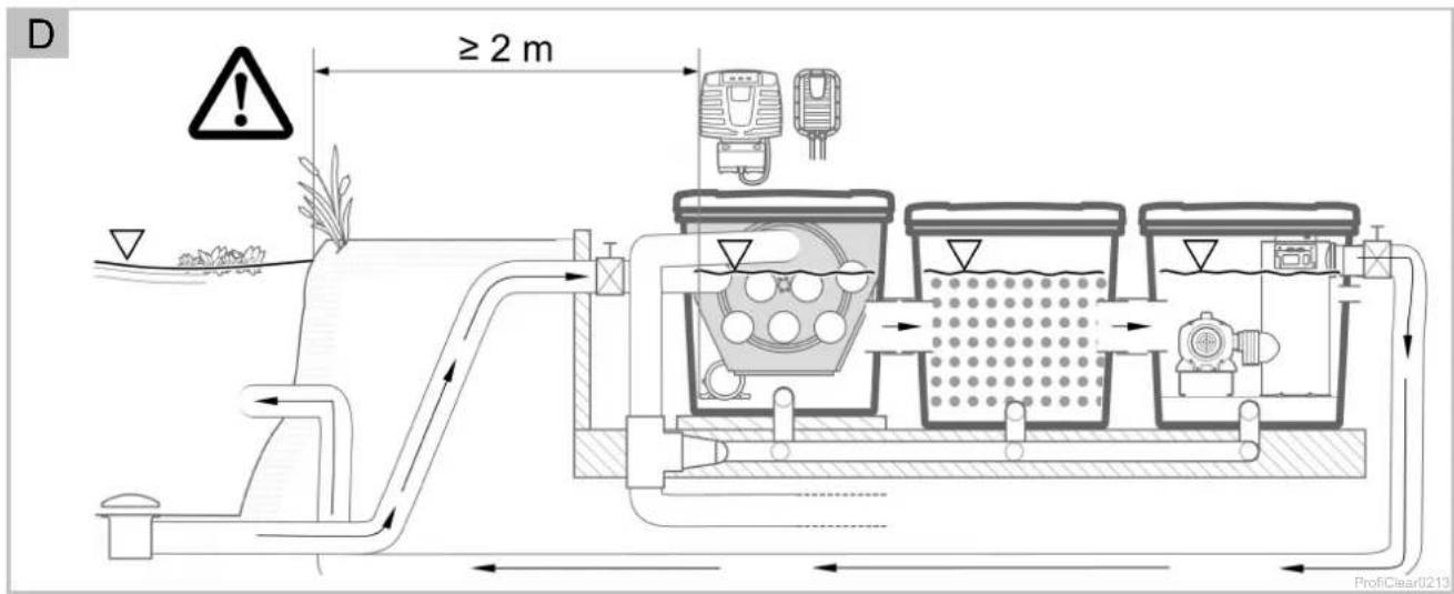
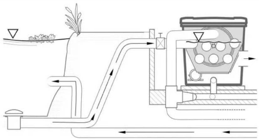
3.3.2 Gravity fed system
□D
The filter system is completely buried (filter pit). The inlet opening is located beneath the water level of the pond. The dirty pond water enters the first filter container via bottom drains or skimmers and then flows into the following filter modules. According to the principle of communicating pipes (hydrostatic pressure), the water level balances out in the containers to the level of the pond. A pump in the last filter module pumps the clean water via a pipe back into the pond.
Advantages of the gravity fed system:
- Excellent transport and thus effective removal of suspended particles using the principle of gravity
• Energy efficient due to negligible height differences and low frictional losses - Can be unobtrusively integrated in a water garden
• UVC clarifiers can be connected in series downstream and are subject to less soiling. - Ideally adapted to OASE filter pumps AquaMax Eco Gravity and AquaMax Eco Titanium.
3.4 Easy Garden Control System (EGC)
This product can communicate with the Easy Garden Control-System (EGC). EGC allows convenient control in the garden and pond via smartphone or tablet, and ensures maximum convenience and reliability. Information about EGC and the possibilities it offers can be found at www.oase.com/egc-start.
3.5 Intended use
Only use the product described in this manual as follows:
- For cleaning garden ponds and natural water features.
- Operate in accordance with instructions. (→ Technical data)
The following restrictions apply to the unit:
- Only operate with water at a water temperature of +4 °C to +35 °C.
- Never use the unit with fluids other than water.
- Not suitable for salt water.
- Never run the unit without water.
- Do not use in conjunction with chemicals, foodstuff, easily flammable or explosive substances.
- Do not use for commercial or industrial purposes.
- This is a class A unit. The unit may cause malfunctions in living environments. It is the user's responsibility to take suitable countermeasures.
4 Installation and connection

NOTE
If the planned installation deviates significantly from the recommendations contained in this manual:
- Have your specialist retailer check whether all technical specifications were adhered to. This is crucial for a problem-free operation.
4.1 Fitting the filter container
□ E

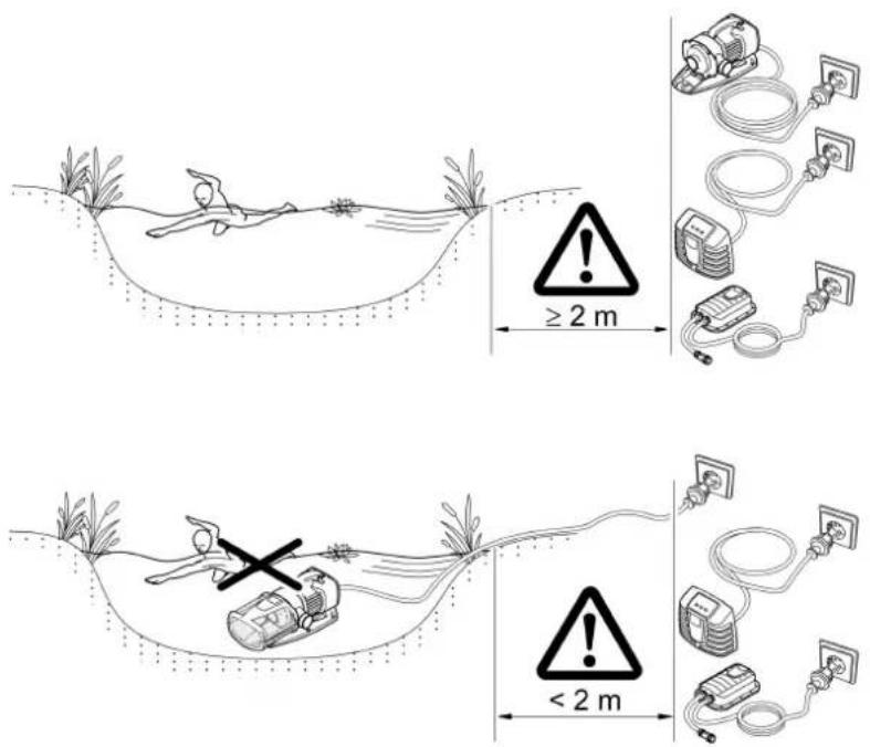
WARNING
Electrical current may cause death or severe injuries.
- Only use electrical units or installations with a rated voltage of U ≤ 12 V in swimming ponds.
- Electrical installations with a rated voltage of U > 12 V must be installed at a distance of at least 2 m from the swimming pond.

CAUTION
Due to the high weight of the unit, spinal injuries or crushing of limbs is possible when carrying the unit. The unit weighs more than 25 kg.
- Use suitable lifting equipment (e.g. special load handles).
- Have the aquarium and cabinet carried by several persons to spread the load and protect against spinal injuries.
- Protect limbs from crushing.
- Do not transport the unit when it is filled.
Plan the installation of the filter system. With careful planning, taking the ambient conditions into account, you will obtain optimum operating results.
The following conditions must be met:
- As the filter modules are very heavy when filled, they must be placed on a suitable base (at least on slabs, but preferably on a poured concrete base) to prevent them from subsiding.
- Plan sufficient space for carrying out cleaning and maintenance work.
- Drain the dirty water into the drain or far enough away from the pond so that it cannot flow back into the pond.
- If the coarse soiling and dirty water both run into the same pipe, it is important to use at least DN 110 pipes.

TIP
The filter system operates day and night and causes rinsing noises during the automatic cleaning cycles.
- Please protect the general public and your neighbourhood from noise disturbance and comply with the statutory noise regulations.
- Enclose the filter system such that the enclosure effectively absorbs the noises.
- Select the location of the filter system in order to avoid noise disturbance.

TIP
A water course or waterfall guarantees optimum water return to the pond. In this way, the filtered pond water is enriched with oxygen before it is returned to the pond.
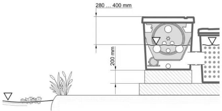
4.1.1 Pump-fed system
□ F
- Align the base slab horizontally.
- Install the drum filter module 200 mm higher than the subsequent Moving Bed module, so that the connections of the two modules (outlet and inlet) are at the same height.
- Tip: Use 24 commercially available concrete slabs of 500 × 500 × 50 mm each to create a base surface of 1500 × 1000 mm and construct four layers on top of each other.
- Position the outlet of the filter system so that the water level in the drum filter module is 280 ... 400 mm below the edge of the container.
- Otherwise, optimum or fault-free operation will not possible.
- When using the pump-fed ProfiClear Premium XL drain module, the correct water level will establish itself automatically.
- Ensure that the inlet to the pond (e.g. via a stream or waterfall) is not positioned higher than the outlet of the filter system.
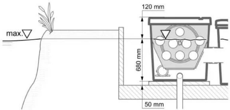
4.1.2 Gravity fed system
□G
The correct installation and constant water level in the pond are important prerequisites for ensuring optimum and fault-free operation of the gravity fed system.
Making a filter pit:
- Excavate a pit of sufficient dimensions to accommodate the filter system.
- Align the base slab horizontally.
- Secure the walls of the pit from falling in (with masonry or concrete).
- Ensure that the pit is protected from flooding. Provide a rain water drain.
Installing the filter system:
• Determine the max. water level for the pond.
- Keeping the water level constant:
- The base slab supporting the filter system must be 680 mm below the max. water level (max. tolerance: -20 mm).
- A constant water level in the pond is necessary for operating the gravity fed system. Tolerances of up to -20 mm from the max. water level are permitted.
- If the max. water level in the pond is exceeded, water flows out of the drum filter module via the dirt channel until the max. water level is reached again.
- If the water level goes below the max. water level by more than 20mm , it is not possible to achieve optimum or fault-free operation.
- Recommendation: ProfiClear Guard automatically refills the pond with water, if the water level drops below the permissible level.
4.2 Connecting the drum filter
4.2.1 Information regarding pipes
- Use suitable pipes.
- Do not use any right-angled bends. Bends with a maximum angle of 45^ are very efficient.
- Glue plastic pipes to ensure a permanent and reliable joint or use socket joints with clips to stop them from coming apart.
- Standing water in pipes can freeze when there is a hard frost and cause pipes to burst. For this reason, lay the pipes and hoses with a gradient (50 mm/m) to ensure that they can run empty.
- For gravity fed systems, it must be possible to shut off the supply from the pond and the return to the pond for maintenance and repair work. For this reason, install suitable slide valves.
- In the case of the gravity fed system, the sum of the losses in the supply line must not exceed 7 mbar (7 cm).
- Otherwise the water level in the filter system will go below the minimum water level during operation. Optimum, fault-free operation will no longer be possible.
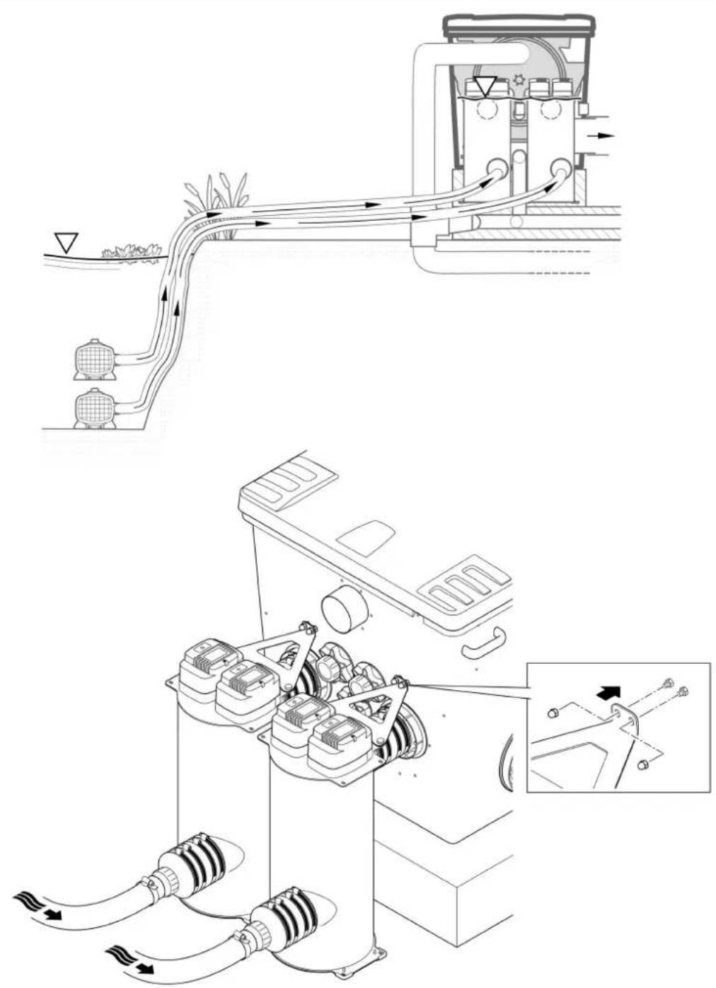
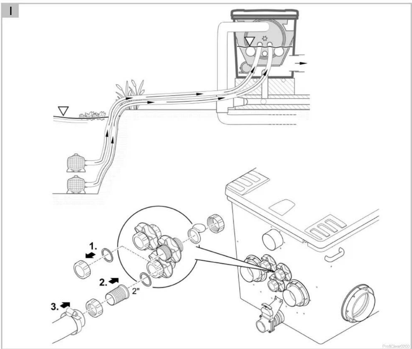
4.2.2 Connecting the inlet of the pump-fed system
□ H, I
The drum filter module is equipped with two DN 110 connections and three 50 mm (G2) connections. The DN 110 connections should be used preferentially.
- One UVC clarifier Bitron Premium or one filter pump (with OASE accessories 77191, 73751) can be connected to each DN 110 connection.
- To increase circulation capacity, up to three additional filter pumps can be connected to the 50 mm (G2) connections.
- Continuous operation of the filter pumps is possible without non-return valves. This reduces pressure losses.
- The integrated non-return valves also make intermittent operation of filter pumps on the 50 mm (G2) connections possible.
Installing a UVC clarifier
How to proceed:
- Connect the UVC clarifier. (→ Operating instructions Bitron Premium)
□H - Use the triangular plate to fasten the Bitron Premium to the container.
50 mm (G2) connection
How to proceed:
□1
- Undo the threaded cap with flat seal from the connection.
- Screw the union nut with 50 mm (G2) hose connector and flat seal onto the connection. Hand-tighten the union nut.
- Slip the 50 mm (G2) hose of the filter pump onto the hose connector and secure with a hose clip.
4.2.3 Connecting the inlet of the gravity-fed system
□J
The drum filter module is equipped with seven DN 110 connections, to which the inlets from the pond can be connected via pipes.
- Recommendation: Limit the flow rate for each DN 110 inlet to 10000 l/h.
- Use suitable DN 110 pipes for connecting the bottom outlet and/or skimmer and the inlet.
• Assembly material for connecting the DN 110 pipe: OASE accessories 73751. - Secure the pipes so that fish cannot swim into them.
4.2.4 Connecting the dirt outlet
□ A, B
The coarse dirt that collects in the dirt channel drains away via the DN 110 coarse dirt outlet (top outlet on the container).
- Connect a suitable DN 110 pipe and drain the dirty water into the sewer system.
The water in the container can be drained via the DN 75 dirt outlet with slide valve at the bottom of the container if required (for cleaning, repair, overwintering).
- Connect a suitable DN 75 pipe and drain the dirty water into the sewer system.

TIP
It is possible to bring together pipe DN 75 and pipe DN 110 from the drum filter for coarse dirt in order to drain the dirty water into the sewer system through a joint pipe DN 110.
This makes it more convenient to flush out the dirty water pipe with sufficient pressure.
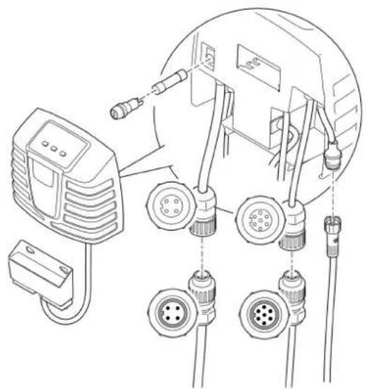
4.3 Connecting the control system
The cable harness contains the connection cables of the signal box, the drum motor and the rinsing pump. These connection cables have to be connected, the EGC box is already connected.
□K
- Connect the three connectors of the cable harness to the control system sockets. Hand-tighten the union nuts.
- The connections are designed to prevent reverse polarity.
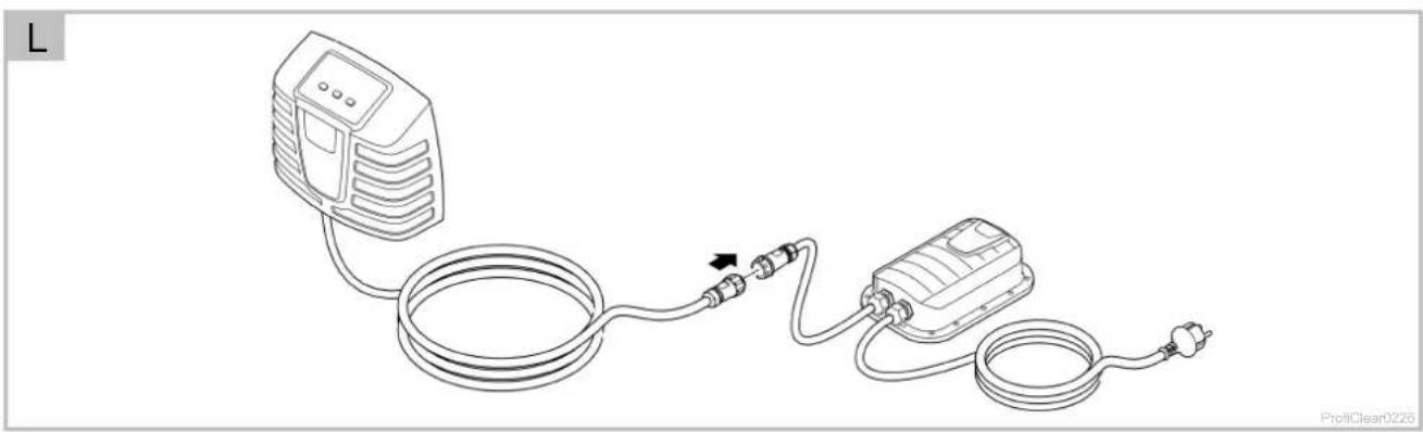
4.4 Connecting the power pack
The power pack is used to supply power to the control system and the drum motor.
- Always disconnect or establish the plug connection to the control system while no current is applied. To do so, disconnect the power pack from the power supply.
How to proceed:
□L
- Connect the plug on the control system with the socket on the power pack. Hand-tighten the union nut.
- The connections are designed to prevent reverse polarity.
4.4.1 Connecting the EGC box
□M
Integration of the filter system into the EGC network is optional and not necessary for operation. (→ Easy Garden Control System (EGC))
The Connection Cable EGC cable is required for connecting the EGC box.
The correct fastening of the plug connector is important for a secure connection and an interference-free EGC network.
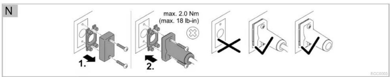
How to proceed:
□ N
-
Remove the protection cap from EGC-IN.
-
Fit the plug connector of the ECG connection cable and secure with the two screws (max. 2.0 Nm).
- Ensure that the rubber seal is clean and fits exactly.
– Replace the rubber seal if damaged.
- Remove the protection cap from EGC-OUT, fit the terminal resistor and secure it with the two screws (max. 2.0 Nm) or another EGC compatible unit.
- No Connection Cable EGC is connected to EGC-OUT on the last unit in the EGC network. The terminal resistor has to be fitted to this EGC-OUT so that the EGC network is correctly terminated.
- The terminal resistor is included in the delivery scope of the InScenio FM-Master EGC or EGC-Controller.
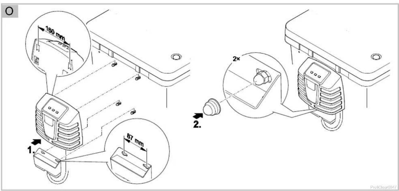
4.5 Installing the control system with EGC box
4.5.1 Pump fed system
• Install the control system at a minimum distance of 2 m from the pond.
- Protect the control system from direct sun radiation.
- The control system is splash-proof and may be exposed to rain.
How to proceed:
□ O
- Either attach the control system and EGC box to the container wall or use threaded hooks to mount it in different position.
- If the EGC box is attached to the container wall, fit both caps onto the cap nuts. – The caps fix the EGC box in place.
4.5.2 Gravity fed system
□ P
• Install the control system at a minimum distance of 2 m from the pond.
- Protect the control system from direct sun radiation.
- The control system is splash-proof and may be exposed to rain.
- Push both ground stakes onto the control system and push the ground stakes into the ground.

NOTE
- Protect the control system from knocks/impact.
- Push both ground stakes onto the control system.
- With light pressure push the ground stakes into the ground to mark the position.
If the ground is hard:
- Detach the ground stakes from the control system and drive them into the ground.
- Then push the control system onto the stakes.
5 Commissioning/start-up
- Thoroughly clean the pond before starting up the filter system for the first time to ensure that the filter system is not overloaded by excessively soiled water. OASE recommends using the PondoVac pond vacuum cleaner for cleaning the pond.
- This cleaning measure is normally not necessary for newly installed ponds.
- It is necessary to operate the filter system for 24 hours a day during the pond season.

WARNING
Possible death or severe injury from hazardous electrical voltage!
- Prior to reaching into the water, isolate (switch off and disconnect) all units/devices used in the water.
- Isolate the device (disconnect from the power supply) before carrying out any work on it.

NOTE
The unit will be destroyed if it is operated with a dimmer. It contains sensitive electrical components.
- Do not connect the unit to a dimmable power supply.
- Do not transport the unit when it is filled.

NOTE
Never allow the rinsing pump to run dry. Possible consequences: The rinsing pump will be destroyed.
- Check the water level at regular intervals. Ensure that the rinsing pump is always under water during operation.
- Do not switch on the control system until the container is flooded with water.

TIP
During commissioning, Er-88 is indicated in the display of the control system,
• for as long as the final water level is not reached in the filter container,
- when the pump status detection is not correctly set.
If the filter system operates correctly, the system message will reset automatically.
5.1 Pump-fed system
5.1.1 Order of starting up steps
How to proceed:
□ A
- Close the slide valve for the dirt outlet at the bottom of the container.
- Check that the entire filter system (pipes and hoses) is complete.
- Remove the container cover.
- Manually turn the filter drum for one whole rotation to ensure unobstructed movement.
- Fill the filter with water until the rinsing pump is submerged (dry run protection of the rinsing pump).
- Fit the container cover.
- The filter drum is stopped for safety reasons if the filter cover is lifted.
- Switch on the control system and perform any necessary adjustments. (→ Operation)
- Switch on the filter pump and UVC clarifier (if applicable). – Ensure that the water is returned to the pond via the return pipe.
- Check all pipes, hoses and their connections for leaks.
- Expansion seals may leak initially until they have fully expanded on contact with water.
- Adjust the level detection device, if necessary. ( Setting the level detection device)
5.1.2 Setting the level detection device
□Q
In the case of pump-fed systems, the water level in the filter system is independent of the water level in the pond. The water level in the filter system is dependent upon the circulation capacity. Therefore it may be necessary to adjust the level detection device.
The level detection device can be fitted in three positions. This information is based on the assumption that at least one DN 110 drain is used as a return line to the pond on the pump-fed Premium XL drain module for each 12500 l of flow volume.
- Position 1: For high flow volumes of >45000 l/h and/or severely contaminated ponds.
- Position 2: For normal flow volumes of 30000 ... 45000 l/h (condition on delivery).
- Position 3: For low flow volumes of < 30000l/h (lower rinsing frequency).
How to proceed:
- Undo both lock nuts. Remove nuts and Allen screws.
- Move the level detection device according to the hole pattern and fix in place with Allen screws and lock nuts. Tighten both nuts.
5.2 Gravity-fed system
5.2.1 Order of starting up steps
How to proceed:
□ B
- Close the slide valve for the dirt outlet at the bottom of the container.
- Check that the entire filter system (pipes and hoses) is complete.
- Remove the container cover.
- Manually turn the filter drum for one whole rotation to ensure unobstructed movement.
- Open the slide valve at the inlet and outlet, if applicable, to fill the filter system with water.
-
Fill the pond until the maximum water level is reached.
-
Check the water level in the drum filter module. Refer to the sticker with level markings on the inside wall of the container.
-
Ideal water level: 120 mm below the top edge of the container
- Permissible tolerance: -20 mm (140 mm below the top edge of the container)
-
Correct the installation if the minimum water level is not reached.
-
Check all pipes, hoses and their connections for leaks.
- Expansion seals may leak initially until they have fully expanded on contact with water.
- Fit the container cover.
- The filter drum is stopped for safety reasons if the filter cover is lifted.
-
Switch on the control system and perform any necessary adjustments. (→ Operation)
-
Switch on the filter pumps and, if necessary, the UVC clarifiers in the ProfiClear Premium XL drain module.
-
Adjust the level detection device to the water level in the filter system. ( Setting the level detection device)
-
If necessary, adjust the filter pump status detection. (→ Setting the filter pump status detection)
5.2.2 Setting the level detection device
Adjust the level detection device to the water level in the container to ensure the optimum operation of the filter system. A 10 mm open jaw spanner is required for this adjustment.
How to proceed:
□ R
- Remove the container cover.
- The filter drum is stopped for safety reasons if the filter cover is lifted and E_rH is indicated in the display of the control system.
- Switch off the filter pumps and check the water level.
- Ensure that the water level reaches the height of the maximum mark on the inside wall of the container, at least above the Min. mark.
- Adjust the water level in the pond if necessary.
- Switch off the mains voltage (ensure that the control system is isolated).
- Loosen both screws of the level detection device so that it can be easily moved.
- Fit the container cover.
- Switch on the control system and filter pumps and start a cleaning cycle.
- Isolate the control system and remove the container cover.
- Move the level detection device until the marking on the housing coincides with the water level.
- Tighten the two screws of the level detection device.
- Replace the container cover and switch on the control system.

TIP
- Perform the setting quickly following the cleaning cycle. The screen elements continually trap dirt particles. This causes the water level to drop in the container.
- Subsequently start a new cleaning cycle and check the setting. Check the setting if necessary.
- Check the setting again when the desired water quality has been reached.
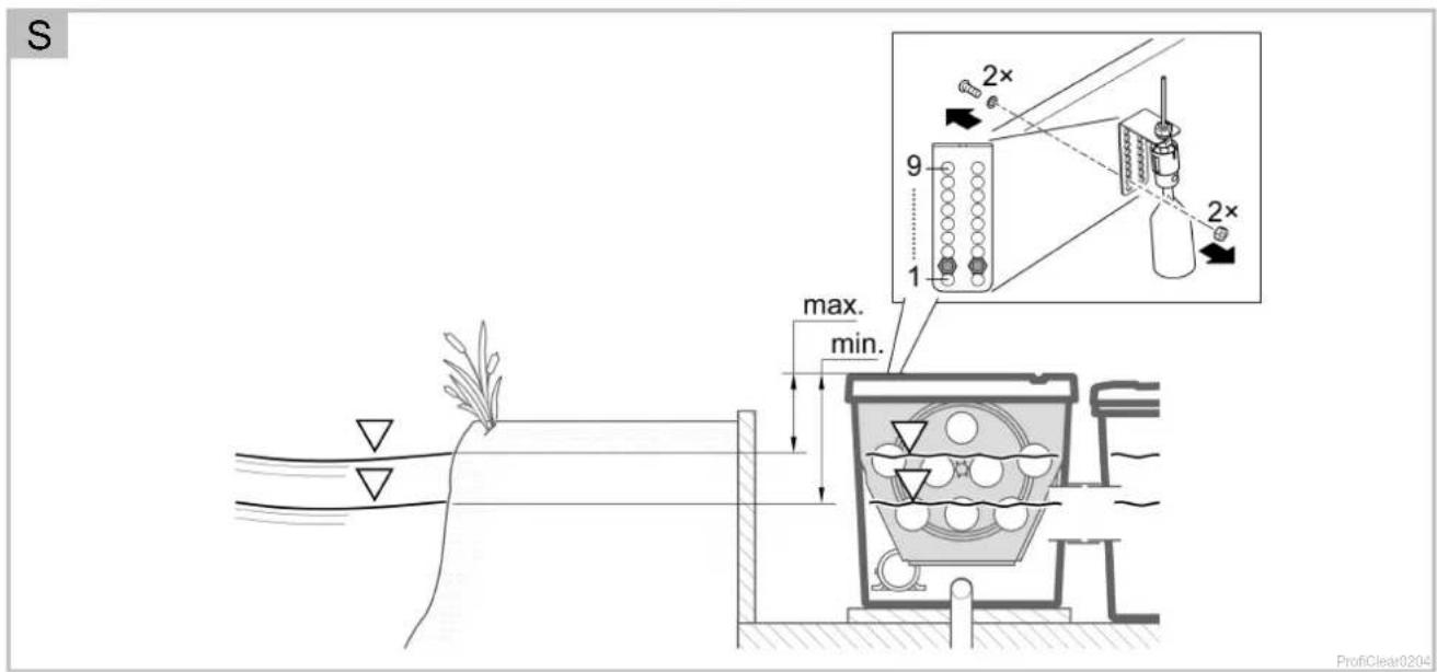
5.2.3 Setting the filter pump status detection

TIP
Setting is only necessary in the following circumstances:
- The installation height of the filter container differs from the system-specific requirements.
- The admissible frictional resistances in the supply lines differ considerably from those specified.
The filter pump status detection signals via the system message Er-88 if the filter pumps are operating correctly.
- If the filter pumps are switched on and running without malfunctions, the water level in the drum filter drops and the float is suspended freely.
- If the flow volume drops (e.g. malfunction on a filter pump), the water level rises and the system message Er-BB is triggered.
- The system message E_r-88 is not triggered unless the status detection is activated for 10 minutes continuously. This prevents brief fluctuations in the water level from triggering the system message E_r-88 .
Check the setting according to the water level in the filter container and correct it if necessary to ensure that the status detection sends the correct signal. In addition, the losses in the supply lines due to the filter pumps must be at least 3.5 mbar (3.5 cm).
- The status detection can be deactivated if necessary. (→ Setting the filter pump status detection)
How to proceed:
□S
- Remove the container cover.
- The filter drum is stopped for safety reasons if the filter cover is lifted and E_eff is indicated in the display of the control system.
- Switch off the filter pump.
- Switch off the mains voltage (ensure that the control system is isolated).
- Measure the distance between the top edge of the container and the level of the water and determine the necessary position of the holder according to the table.
- If the determined position differs from the current position, correct it as required.
- Undo and remove both screws of the holder. Push the holder into the correct position and fasten with both screws.
- Fit the container cover.
- Switch on the control system and filter pumps and check the function of the status detection.
The status detection is correctly set if the float sinks with the filter pump switched on and the system message Er-BB is only triggered 10 minutes after the filter pump is switched off.
| ☐ S | Water level in the filter container/pond (measured from the top edge of the container with the filter pump switched off) |  | |
| max. | min. | ||
| 169 mm | 189 mm | 9 | |
| 162 mm | 182 mm | 8 | |
| 155 mm | 175 mm | 7 | |
| 148 mm | 168 mm | 6 | |
| 141 mm | 161 mm | 5 | |
| 134 mm | 154 mm | 4 | |
| 127 mm | 147 mm | 3 | |
| 120 mm | 140 mm | 2^1) | |
| 113 mm | 133 mm | 1 | |
^1) Factory setting
6 Operation
6.1 Control system overview
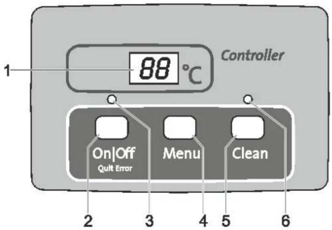
ProfiClear 0001
1 Display
• Display of the operating status
• Display of menus and values for setting the drum filter
- Pump status display
- The current water temperature [°C] is displayed by default
2 On|Off button, Quit Error
- Switching the drum filter on or off
- Reset error messages
3 LED, 2 colours
- LED is lit red: Control system switched OFF (OFF)
• LED is lit green: Control system switched ON (ON)
4 Menu button
For selecting the following menus and changing the values:
- Cleaning time "Cleaning" (CL)
- Extended cleaning time "Extra Cleaning" (EC)
• Time-dependent cleaning "Interval" (I _n )
- Pump status detection (E7)
5 Clean button
- Starting the manual cleaning cycle and cancelling the active cleaning cycle
• LED (6) is lit when the cleaning cycle is active
6 Blue LED
• LED is lit: Cleaning cycle active
6.2 Switching ON/OFF
| Proceed as follows | Information |
| Switching on:Press [IMAGE] for 3 s.LED (3) is lit green.The display indicates O_n for approx. 5 s. | The display indicates the water temperature by default.If there is a voltage interruption, the control system will remain switched on. |
| Switching off:Press [IMAGE] for 3 s.LED (3) is lit red.The display indicates OFF. | The control system switches off all functions.If there is a voltage interruption, the control system will remain switched off. |
6.3 Operating modes
| Description | Information |
| Automatic mode:• Operating mode for normal operation. | The display indicates the water temperature as standard.A cleaning cycle is automatically started if the level detection device signals an excessive deviation in the water level.The level exceeds a certain water level.After 20 automatic cleaning cycles, a cleaning cycle with extended cleaning time is performed. |
| Time-dependent operation | In addition to the automatic cleaning cycle (depending on the water level in the drum filter), a time-controlled cleaning cycle can be executed. ( l_o : Time-dependent cleaning "Interval")The duration of the cleaning cycle corresponds to the time set in the cleaning time "Cleaning" menu. ( L : Cleaning time "Cleaning") |
6.4 Manual cleaning
| Proceed as follows | Information |
| Press forLED (6) is litThe display indicatesCLTo cancel the process: Press the button again | The drum motor is stopped for safety reasons if the filter cover is lifted. The rinsing pump can still be manually started to check the function of the nozzles.Each active cleaning cycle (automatic, time-dependent or manual) can be stopped by pressing the button. |
6.5 Settings in the menus

TIP
Settings can only be made in the menus when the control system is switched on.
6.5.1 CL: Cleaning time "Cleaning"
Setting the cleaning time changes the duration of the cleaning cycle. Extend the cleaning time if the dirt is not completely carried away by the water. This may become necessary if, for instance, very long drain pipes or drain pipes with many bends were installed or there is a particularly large amount of sticky dirt (e.g. during spawning).
Please take into consideration that an extended cleaning time leads to increased water consumption. The default setting of 10 s is normally sufficient (corresponds to approx. a 78 drum rotation).
| Proceed as follows | Information | |
| 1. | Press several times until appears in the display. | To cancel and exit the menu: Either wait for 10 s or press  Clean Clean |
| 2. | Press for 5 s until the time is indicated in the display. | To cancel and exit the menu: Either wait for 5 s or press  or Clean or Clean |
| 3. | Press several times to change the value.To change the value quickly: Hold down the button | Adjustable range: 10 – 30 sIncrement: 1 sThe number can only be changed upwards. Once the value 30 is reached, the display returns to 10.Saving the set value: Wait for 5 s until the menu is automatically exited.Cancel without saving and exit the menu: Press  or or  |
In addition to automatic cleaning, the unit can also perform a time-dependent cleaning cycle. This is particularly useful for ponds containing fish, because even if there is only a small amount of dirt, excrement is always removed from the water cycle before it leads to a build-up of nutrients.
Adjust the time interval to meet the requirements. The optimum setting of the drum filter module is usually a time interval of 20 minutes (default setting). The function is deactivated at a time setting of 0 minutes.
The time-dependent cleaning cycle does not have any influence on the automatic cleaning cycle that starts when the water level is too low. After each automatic cleaning cycle, the time interval is reset and starts again from the beginning.
| Proceed as follows | Information | |
| 1. | Press several times until In appears in the display. | To cancel and exit the menu: Either wait for 10 s or press onOff or Clean. |
| 2. | Press for 5 s until the time is indicated in the display. | To cancel and exit the menu: Either wait for 5 s or press onOff or Clean. |
| 3. | Press several times to change the value.To change the value quickly: Hold down the button. | Adjustable range: 0.3 – 60 min0 min: No time-dependent cleaningIncrement: 1 minThe number can only be changed upwards. Once the value 60 is reached, the display returns to 0.Saving the set value: Wait for 5 s until the menu is automatically exited.Cancel without saving and exit the menu: Press onOff or Clean. |
6.5.3 EC: Extended cleaning time "Extra Cleaning"
To prevent larger deposits from building up in the dirt channel or pipework, the unit has an extended cleaning time option. The extended cleaning time starts after a definable number of cleaning cycles. (→ lE: Interval of the extended cleaning time "Interval Extra Cleaning")
You can increase the cleaning time to flush out the pipe with additional water. The default setting for the extended cleaning time is 20 s.
| Proceed as follows | Information | |
| 1. | Press several times until EC appears in the display. | To cancel and exit the menu: Either wait for 10 s or press on/off or Clean. |
| 2. | Press for 5 s until the cleaning time is indicated in the display. | To cancel and exit the menu: Either wait for 5 s or press on/off or Clean. |
| 3. | Press several times to change the value.To change the value quickly: Hold down the button. | Adjustable range: 10 s – 9 min.–A value in minutes is displayed with a line on the display (e.g. ' ).Increment for 10 – 59 s: 1 sIncrement for 1 – 9 min: 1 Min.The number can only be changed upwards. After the value 9 min, the displayreturns to 10.Saving the set value: Wait for 5 s until the menu is automatically exited.Cancel without saving and exit the menu: Press on/off or Clean. |
6.5.4 IE: Interval of the extended cleaning time "Interval Extra Cleaning"
This menu is used to set the number of cleaning cycles after which an extended cleaning time “Extra Cleaning” is performed.
The default setting is one extended cleaning time “Extra Cleaning” after 20 cleaning cycles.
| Proceed as follows | Information | |
| 1. | Press several times until /£ appears in the display. | To cancel and exit the menu: Either wait for 10 s or press on/Off or Clean. |
| 2. | Press for 5 s until the cleaning time is indicated in the display. | To cancel and exit the menu: Either wait for 5 s or press on/Off or Clean. |
| 3. | Press several times to change the value.To change the value quickly: Hold down the button. | Adjustable range: 20 ... 99 rinsing cyclesIncrement: 1The number can only be changed upwards. Once the value 99 is reached, the display returns to 20.Saving the set value: Wait for 5 s until the menu is automatically exited.Cancel without saving and exit the menu: Press on/Off or Clean. |
6.5.5 E7: Pump status detection
The pump status detection signals whether the pump is operating properly via the Er-88 system message. The status detection is activated in the default setting.
| Proceed as follows | Information | |
| 1. | Press several times until £7 appears in the display. | To cancel and exit the menu: Either wait for 10 s or press on/off or Clean. |
| 2. | Keep pressed for 5 s until the value 0 or 1 is indicated in the display. | To cancel and exit the menu: Either wait for 5 s or press on/off or Clean. |
| 3. | Press change the value. | Adjustable range: 0 or 10: The pump status detection is deactivated.1: The pump status detection is activated.Cancel without saving and exit the menu: Press on/off or Clean. |
6.6 Reading out the number of cleaning cycles
6.6.1 Cleaning cycles in 24 hours
| Proceed as follows | Information |
| Press and for 5 s. | The sum of the automatic and time-dependent cleaning cycles is saved. The 4-digit value is displayed in groups of two digits that appear in succession in the display.Example:01-17: Represents 117 cleaning cyclesThe number is repeated five times after an extended pause to make it easier to read:01-17---01-17---01-17---01-17---01-17Note:If the mains voltage is switched off, the counter is reset to 0.Note:Due to the self-test of the filter system very different values may be displayed. The self-test monitors the automatic cleaning process. The test is carried out continuously in a 2 × 24 hour cycle. The test is only active from a water temperature >12 °C.First 24 hour cycle– If at least one automatic cleaning process is detected, the cycle is repeated after the cleaning process has finished.– If no automatic cleaning process is detected, the second 24 hour cycle starts once the first has finished.Second 24 hour cycle– The time-dependent cleaning cycle is deactivated. This reduces the number of cleaning cycles.– If at least one automatic cleaning process is detected, the first 24 hour cycle starts again once the cycle has finished.– If no automatic cleaning process is detected, the system message E_r-22 is triggered at the end of the cycle. The time-dependent cleaning cycle starts again. If an automatic cleaning process is then detected, the first 24 hour cycle starts again. The system message E_r-22 is automatically reset. |
6.6.2 Total cleaning cycles
| Proceed as follows | Information |
| PressOnOffandCleanfor 5 s. | The sum of the automatic, manual and time-dependent cleaning cycles is saved. The 8-digit value is displayed in groups of two digits that appear in succession in the display.Example:00-00-12-44: Represents 1244 cleaning cyclesThe number is repeated four times after an extended pause to make it easier to read:00-00-12-44---00-00-12-44---00-00-12-44---00-00-12-44Note:If the mains voltage is switched off, the number of cycles is rounded off to the nearest hundred and saved. |
6.7 Loading default settings
| Proceed as follows | Information |
| Press [IMAGE] and [IMAGE] for 10 s until rE appears in the display. | All individually set values are overwritten!The following values are set:Cleaning time CL: 10 sExtended cleaning time EC: 20 sInterval of the time-dependent cleaning h: 20 minInterval Extra Cleaning IE: Every 20 rinsing cycles |
EN
6.8 System messages
The 4-digit system message is indicated in the display by two groups of two digits in succession.
| System message | Functions that are still available | Possible cause | Remedy | Resetting the system message | |
| Er-11 | Container cover raised | · Manual cleaning (only nozzles, filter drum not rotating) | Container cover raised | Refit the container cover | Automatic when the container cover is replaced |
| Container cover incorrectly fitted | Turn the container cover around so that the magnets in the container cover are located over the signal box | ||||
| Signal box not connected | Connect the signal box to the control system | ||||
| Er-22 | Water temperature > 12 °C AND the last automatic cleaning process was carried out more than 24 hours ago. | · Manual cleaning · Automatic mode · Time-dependent cleaning · Extended cleaning time "Extra Cleaning" | Screen elements leaking | Check screen elements, replace if necessary | · Press key for 5 s · Automatic as soon as the level detection device is triggered |
| Drum seal leaking | Check the drum seal | ||||
| Level detection device stuck or defective | Clean the level detection device to ensure that the mechanism operates freely, replace if necessary. | ||||
| Level detection device set incorrectly | Adjust the level detection device (→ Commissioning/start-up) | ||||
| Er-33 | 20 cleaning cycles in succession | · Manual cleaning · Time-dependent cleaning · Extended cleaning time "Extra Cleaning" | Level detection device stuck or defective | Clean the level detection device to ensure that the mechanism operates freely, replace if necessary. | Press key for 5 s |
| Screen elements heavily soiled | Clean/descale the screen elements (→ Removing the screen element) | ||||
| Rinsing pump not operating | · Clean the bottom of the container, clean the rinsing pump (→ Cleaning the rinsing pump) · Check the pump connection | ||||
| Rinsing nozzles clogged | Clean the rinsing nozzles | ||||
| Filter drum not rotating | · Check the motor connection · Check the rotating movement of the filter drum. To do so, check the markings (1 - 8) on the filter drum to detect a rotating movement. | ||||
| Water in the pond is severely contaminated. | · For the duration of the severe contamination, reduce the flow rate until the error message is no longer displayed. · For the duration of the severe contamination, use screen elements with a larger screen mesh size. | ||||
EN
| System message | Functions that are still available | Possible cause | Remedy | Resetting the system message | |
| E-33 | 20 cleaning cycles in succession | Manual cleaningTime-dependent cleaningExtended cleaning time "Extra Cleaning" | Gravity fed systems only: | Press key for 5 s | |
| Water level is beneath the level detection device | Increase the water level of the pondUse the OASE ProfiClear Guard refill systemSet the level detection to a lower level (→ Setting the level detection device)Setting the level detection to a lower level reduces the movement of the Pond Pads in the filter system. | ||||
| Level detection device set too high | Set the level detection to a lower level (→ Setting the level detection device)Setting the level detection to a lower level reduces the movement of the Pond Pads in the filter system. | ||||
| Water level in the system too low:Excessive flow rate (pump capacity too high)Water supply too lowWater inlet blocked | Reduce flow rate (adjust pump capacity)Select a larger pipe diameter for the water supply if necessaryClean water inlet | ||||
| Pump fed system only: | |||||
| Level detection device set too low | Adjust the level detection device (→ Setting the level detection device) | ||||
| Water level in the system too high:Outlet pipes soiledOutlet opening too smallExcessive flow rate (pump capacity too high) | Clean outlet pipesEnlarge outlet openingReduce flow rate (adjust pump capacity) | ||||
| System message | Functions that are still available | Possible cause | Remedy | Resetting the system message | |
| E-44 | Motor blocked(The control system attempted to start up the motor three times - 5 times per attempt) | None | Filler drum rotating sluggishly or jammed | Clean edge of the drum/drum seal and grease edge of the drum Only use original OASE grease (order number 27872).Ensure that the rollers move smoothlyRemove larger particles (e.g. snails, stones) from the sprocket | Press key for 5 s |
| The lips of the drum seal were squeezed when the drum was installed. | Disassemble the drum and ensure that the drum seal is positioned correctly during re-assembly | ||||
EN
| System message | Functions that are still available | Possible cause | Remedy | Resetting the system message | |
| The drum load is distributed unevenly | • Align the container horizontally | ||||
| Pump fed system only: | |||||
| Water level too low | Ensure that the water level in the drum filter is 280 ... 400 mm below the edge of the container. | ||||
| Gravity fed systems only: | |||||
| Excessive difference in water level inlet side/drum side | • Determine the cause of the difference and eliminate it (e.g. level detection device set too low, screens clogged, rinsing function inactive)• Switch off the pumps and wait until the water level is equal on both sides. Subsequently, switch on the pumps again and check the difference. | ||||
| System message | Functions that are still available | Possible cause | Remedy | Resetting the system message | |
| Er-55 | More than 960 cleaning cycles in 48 hours | • Manual cleaning• Automatic mode• Time-dependent cleaning• Extended cleaning time "Extra Cleaning" | Temporary heavy soiling• Start-up phase of the filter system (e.g. during the first start-up)• Fish are spawning | Wait until the soiling decreases• This operating status is atypical. Avoid long-term operation in this state. | - Press ☐ key for 5 s- Automatic if the number of cleaning procedures drops below 960. |
| Pond heavily soiled | • Clean the pond• Reduce the amount of soiling | ||||
| Screen elements heavily soiled | Clean/descale the screen elements (→Removing the screen element) | ||||
| Insufficient cleaning effect due to soiled nozzles | Clean the nozzles | ||||
| Water level in the system too high:• Outlet pipes soiled• Outlet opening too small• Max. flow rate exceeded | • Clean outlet pipes• Enlarge outlet opening• Reduce flow rate | ||||
| Er-65 | Switch element for rinsing pump in the control system overheated | None | Control system is exposed to excessive heat (sun, ambient temperature) | Protect the control system from heat | Automatic when cooled down |
| Er-85 | The filter pump is not supplying any water or insufficient water. | • Manual cleaning• Automatic mode• Time-dependent cleaning• Extended cleaning time "Extra Cleaning" | Pump status detection incorrectly set | Set the pump status detection. (→ET: Pump status detection) | Automatic after elimination of the cause |
| The filter pump is switched off. | Switch on the filter pump. | ||||
| The impeller unit of the filter pump is blocked. | Clean the filter pump. | ||||
7 Malfunction remedy
| Malfunction | Possible cause | Remedy |
| No flow of water | Filter pump not switched on. | Switch on the filter pump, connect the power plug. |
| Supply to filter system or return to pond blocked. | Clean the supply and/or return. | |
| Water flow insufficient | Bottom drain, pipe or hose blocked | Clean, replace if necessary. |
| Hose kinked | Check hose, and replace if necessary. | |
| Excessive loss in lines | Reduce line length to necessary minimum. | |
| Water remains cloudy | Insufficient pump capacity | Adjust the pump capacity accordingly |
| Excessive pressure loss in the line to the pump | Adjust the pump capacity accordingly• Note the characteristic curve of the pump | |
| The water is extremely soiled. | • Remove algae and leaves from the pond.• If the water is particularly contaminated, change 30 % of the water to avoid damage to the fish. | |
| Dirt particles are not reaching the drum filter module. | • Optimise the water flow so that the skimmer and/or the filter pump can draw in the dirt particles.• Align the skimmer and/or filter pump in relation to the water flow so that they can draw in dirt particles. | |
| Too many pond animals | Reduce number of pond animals | |
| Screen elements clogged or damaged | Clean or replace screen elements | |
| Drum seal incorrectly positioned | Check the position of the drum seal | |
| Drum seal is damaged | Replace the drum seal | |
| Unusual noises in the drum | Large dirt particles have collected in the filter drum | Remove a screen element and remove dirt particles from the filter drum |
| Fish missing | Fish may have swum through a pipe into the filter drum. | Remove screen element, take the fish out of the filter drum and return to the pond |
| Rinsing channel blocked | Large particles of dirt such as string algae are blocking the dirt channel | Remove a screen element and clean the dirt channel. |
| Filter drum is partially soiled, cannot be cleaned | Rinsing nozzles clogged | Clean the rinsing nozzles, replace if necessary |
| In a pump fed system, water is flowing via the emergency overflow | Screen elements clogged | Clean/descale the screen elements |
| Pump capacity too high | Reduce the pump capacity. | |
| Time-dependent cleaning function (interval) does not start | The control system checks the function of the level detection device.• This check is started automatically if too few automatic cleaning procedures have been carried out. | • Wait. The check takes a maximum of 24 hours.• The check is completed once the level detection function is triggered. An automatic cleaning procedure is carried out.• If the level detection device is not triggered within 24 hours, Er-22 is displayed. The time-dependent cleaning cycle is activated. (→ System messages) |
| No display on the control system | Cable not connected | Check cable connection |
| Control system has switched off due to overheating (temperature switch) | Protect the control system from heat and allow it to cool down• The control system will switch back on automatically when it has cooled down• Error message Er-56 gives a warning before the control system overheats | |
| Safety fuse has tripped due to a blockage of the rinsing pump (excessive current consumption) | Clean the rinsing pump ( Cleaning the rinsing pump)Replace the fuseOnly use 5 × 20 mm, 16 A slow-blow / 250 V safety fuse. | |
| Oil film in the drum filter module | Harmless food-grade oil may leak from a new rinsing pump for a short time when first used | No measure is necessary |
8 Maintenance and cleaning

WARNING
Possible death or severe injury from hazardous electrical voltage!
- Prior to reaching into the water, isolate (switch off and disconnect) all units/devices used in the water.
- Isolate the device (disconnect from the power supply) before carrying out any work on it.
8.1 Cleaning the device
- Do not use aggressive cleaning agents or chemical solutions as they could attack the housing or impair the function of the unit.
- Recommended cleaning agent for removing stubborn limescale deposits:
- Pump cleaning agent PumpClean from OASE.
– Vinegar- and chlorine-free household cleaning agent.
• After cleaning, thoroughly rinse all parts in clean water.
8.2 Regular tasks
The filter system is self-cleaning. Carry out the following work regularly to ensure the optimum cleaning capacity of the filter system.
Regular checks
- Check the display of the control system for any system messages. (→ System messages)
- Check the area in front of the separating plate and the inside of the filter drum for excessive soiling (e.g. string algae). To do this, remove a screen element. (→Removing the screen element)
Removing accumulated dirt
Dirt that cannot be collected by the filter drum, sinks to the bottom and has to be removed.
- Open the DN 75 dirt outlet for approx. 10 seconds once per month.
- Remove accumulated dirt in front of the filter drum.
- Remove string algae from the dirt channel.
- Remove accumulated dirt from the level detection device.
8.3 Cleaning the entire filter system
- The entire filter system only needs to be taken out of operation for cleaning and maintenance if it is extremely soiled.
- Do not use any chemical cleaning agents as they would kill the filter bacteria.
How to proceed:
- Switch off all filter pumps.
- Switch off all other electrical units of the filter system (e.g. UVC clarifier).
- Gravity fed systems only: Close the slide valves (supply and return) of the filters connected in series to prevent further water flow.
- Open the slide valve for the DN 75 dirt outlet at the bottom of the container and dispose of the soiled water in a permissible way.
- Carry out cleaning measures.
- Close the slide valve (dirt outlet).
- Start up the filter system again. (→ Commissioning/start-up)
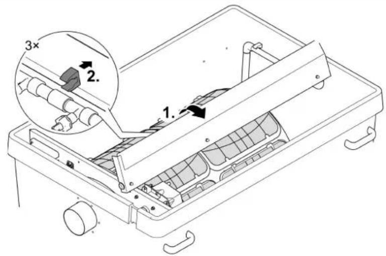
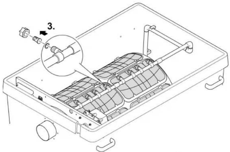
8.4 Cleaning the rinsing device
How to proceed:
□T
- Fold up the cover.
- Remove the clips of the cover from the rinsing pipe, remove the cover and start a manual cleaning process to check that the rinsing nozzles are functional. (→ Manual cleaning)
-
Undo the union nut on the clogged nozzle, remove the nozzle and seal from the rinsing pipe and clean the parts. After completing the cleaning process, push the union nut back onto the nozzle and screw it onto the rinsing pipe together with the seal.
-
Align the nozzle so that the marking is at the top.
- Hand-tighten the union nut.
-
Replace the cover.
-
Position the cover with the clips on the rinsing pipe.
-
Push the rinsing pipe into the clips from the bottom with your fingers while simultaneously applying pressure to the top of the cover.
- Do not apply pressure to the rinsing pipe. The rinsing pipe may be damaged if it is bent.

NOTE
Operation without a cover will impair the function of the rinsing unit. This will lead to poor cleaning results.
• Always operate the rinsing unit with a fitted cover.
8.5 Cleaning the screen elements
8.5.1 Removing the screen element
How to proceed:
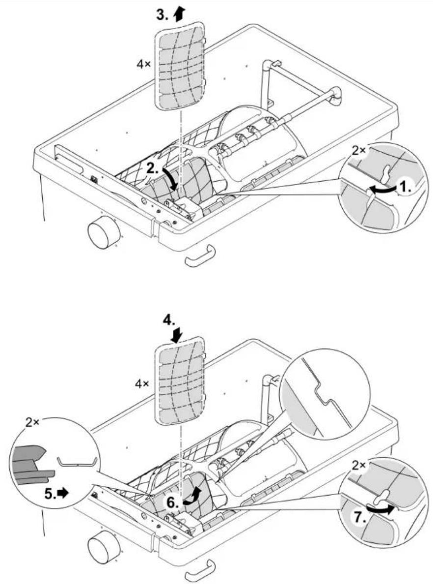
□ U
Removing
- Turn the filter drum manually until the screen element is located opposite the drum motor. Undo the locking mechanism (turn through 180^ ).
- Lower the screen element completely into the filter drum.
- Remove the screen element from the filter drum.
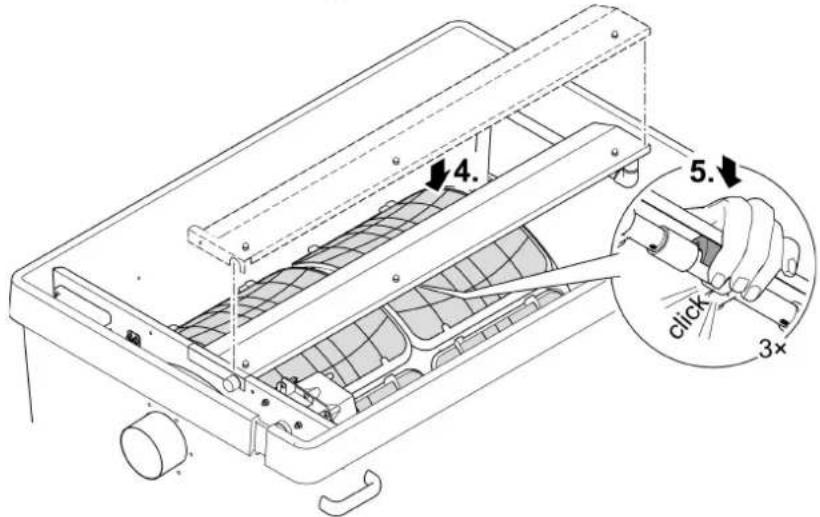
Fitting
- Lower the screen element completely into the filter drum.
- Turn the screen element and push the two hinges onto the support of the filter drum.
- Pull the screen element upwards by the locking mechanisms.
- Ensure that the pin on the filter drum exactly engages in the recess on the side of the screen element.
- Close both locking mechanisms (turn through 180°).
8.5.2 Decalcifying the screen elements
The error messages Er33, Er55 or an excessive rise in the frequency of cleaning cycles (counter) indicate that there are limescale deposits on the screen elements. ( Reading out the number of cleaning cycles)
Oase recommends that you descale the unit every two to three months as a preventative measure if the water is very hard.
Recommended descaling process:
- Place screen elements in vinegar concentrate (20 ... 25 % acid) and let them soak for at least 30 minutes until the limescale deposits have dissolved. or
- Sprinkle citric acid powder onto moistened screen elements and allow it to react for at least 30 minutes until the limescale deposits have dissolved.
How to proceed:
- Remove the screen element. ( Removing the screen element)
- Remove limescale from the screen element.
- Do not remove the rubber seal of the screen element.
- Scrub the screen element with a soft brush under running water and rinse well.
- Refit the screen element.
8.6 Removing the filter drum
How to proceed:
Preparatory work:
- Remove the cover of the rinsing unit. (→ Cleaning the rinsing device)
- Remove the screen elements. (→Removing the screen element)
□V
-
Pull the rinsing unit out of the fastening clips and the separating plate, turn it by 90^ and fold it down over the rear edge of the container.
-
Undo and remove both Allen screws (width across flats 5), pull the drum motor out of the hole in the separating plate and remove.
- Do not allow the drum motor to hang from the connection cable.
-
Undo the Torx screws fastening the dirt channel.
-
Pull the dirt channel from the socket of the dirty water outlet and lift it out of the filter drum.
-
Open the cotter pin and pull it out.
-
Pull out the drum shaft.
-
Pull the filter drum from the separating plate up to the stop and lift it out in a horizontal position.
- Proceed carefully: The fastening clips on the container wall could damage the screen elements.
8.7 Installing the filter drum
How to proceed:
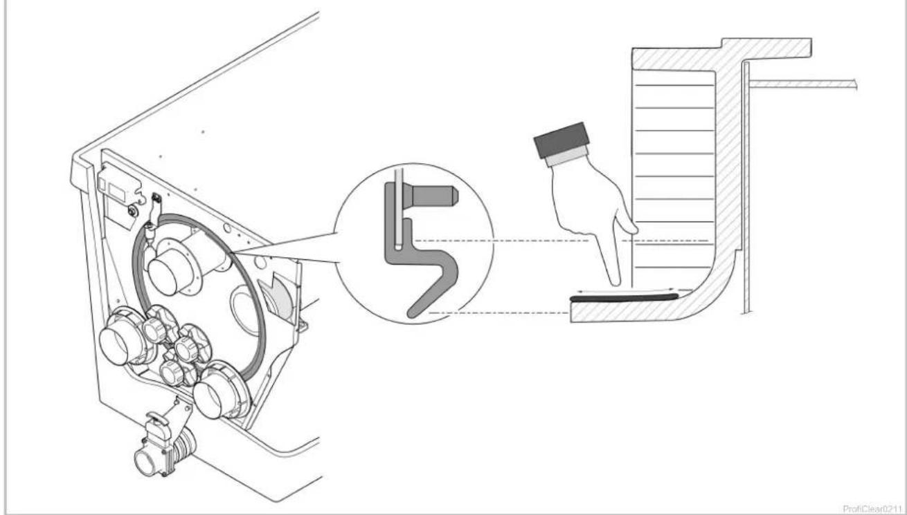
□W
Before fitting the filter drum check that the drum seal is undamaged and correctly positioned.
Replace the drum seal if damaged.
- Fitting a new drum seal: Ensure that the recess in the drum seal is at the top.
- Ensure that the separating plate is completely seated in the groove of the drum seal.
- Grease the edge of the drum to improve the smooth movement of the filter drum.
- Only use original grease (Turmsilon GTI 300 GK) from OASE.
- Continue to assemble in the reverse order.
8.8 Cleaning the rinsing pump

TIP
It is often possible to remove soiling from the rinsing device and rinsing pump by cleaning the rinsing device without the nozzle/nozzles.
- Remove the nozzle/nozzles for cleaning so that the dirt particles are flushed out.
Preparatory work:
- Remove the filter drum. (→Removing the filter drum)
How to proceed:
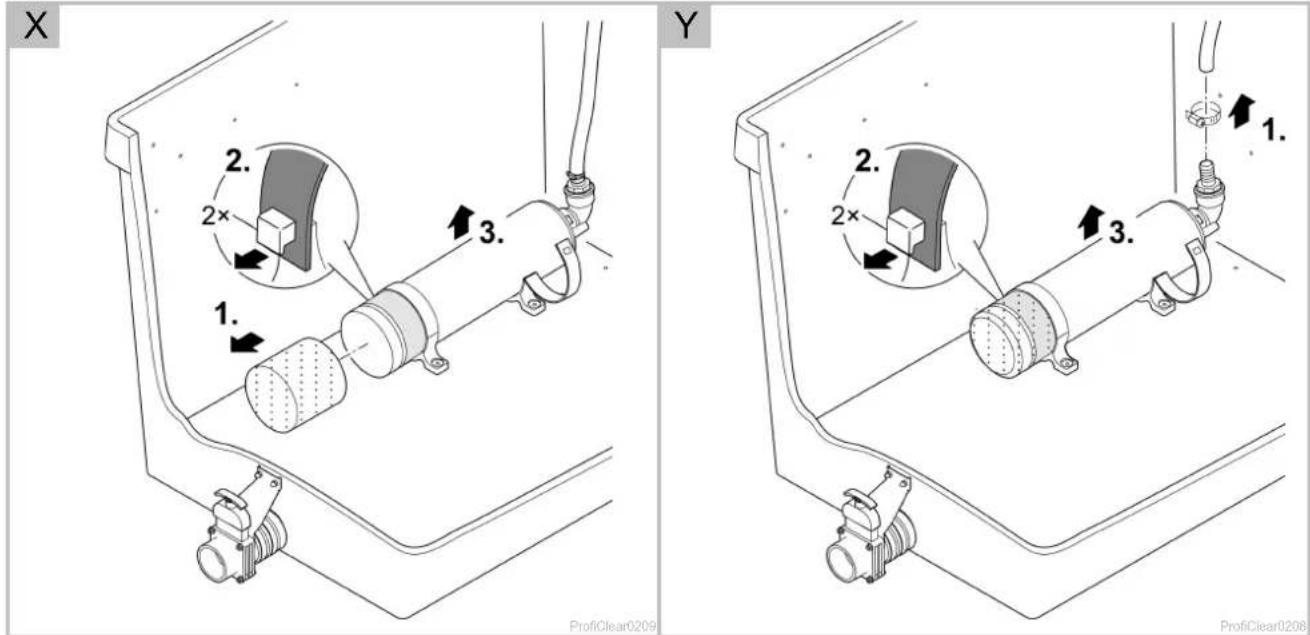
□ X
- Undo the fastening device. To do this, unhook both rubber straps.
- Lift the rinsing pump and remove the filter sock.
– Clean all parts in clean water.
8.9 Replacing the rinsing pump
Preparatory work:
- Remove the filter drum. (→Removing the filter drum)
How to proceed:
□ Y
- Undo the fastening device. To do this, unhook both rubber straps.
- Loosen the hose clip and pull off the hose.
- Take out the rinsing pump and replace.
- Disconnect the connection cable from the cable harness.
- Fit the rinsing pump in the reverse order.
9 Storage/winter protection
The unit is protected from frost (e.g. stored in a garage or other enclosure)
The unit can be operated as long as the water temperature does not go below +4 °C.
- Set the interval for time-dependent cleaning to 20 minutes to avoid damage to the rinsing device in the event of frost.
- Install the control system in such a way that it is protected. The minimum operating temperature of the control system is -10 °C.
The unit is not protected from frost (e.g. outdoor installation)
Take the unit out of operation at water temperatures below +8^ C or, at the latest, when freezing temperatures are to be expected.
- Drain the unit as far as possible, clean thoroughly and check for damage.
• Empty all hoses, pipes and connections as far as possible. - Leave the slide valves open.
- Cover the container so that no rain water can enter.
- Protect pipes and slide valves that are in contact with water from frost.

NOTE
The drum seal requires maintenance after winter or at the beginning of the pond season.
- Remove the old grease, then apply new grease sparingly to the edge of the drum.
10 Wear parts
- Screen elements
- Safety fuse
- Drum seal
- Capacitor of the rinsing pump
- Do not open the rinsing pump. Send the rinsing pump to OASE. You will be sent an immediate replacement.
11 Disposal
Support us in our endeavour to keep our environment intact and adhere to the following disposal information!
Dispose of the unit in accordance with the national legal regulations.

NOTE
Do not dispose of this unit with domestic waste.
- Render the unit unusable beforehand by cutting the cables and dispose of the unit via the return system provided for this purpose.
12 Spare parts

The use of original parts from OASE ensures continued safe and reliable operation of the unit.
Please visit our website for spare parts drawings and spare parts.
| ProfiClear Premium | TF-XL pump-fed EGC | TF-XL gravity-fed EGC | ||
| Control system | Rated voltage | V AC | 230 | 230 |
| Mains frequency | Hz | 50 | 50 | |
| Power consumption in idle state | W | 5 | 5 | |
| Power consumption during cleaning cycle | W | 1100 | 1100 | |
| Maximum power consumption (theoretical) | W | 1600 | 1600 | |
| Rinsing pump output voltage | V AC | 230 | 230 | |
| Drum motor output voltage | V DC | 12 | 12 | |
| Signal box output voltage | V DC | 12 | 12 | |
| Ambient temperature | °C | -10 ... +35 | -10 ... +35 | |
| Safety fuse 5 × 20 mm, 250 V | A | T16 | T16 | |
| Length of power cable | m | 5 | 5 | |
| Length of connection cable to power pack | m | 4.5 | 4.5 | |
| Permissible water temperature | °C | +4 ... +35 | +4 ... +35 | |
| Length of drum filter cable harness | m | 5 | 5 | |
| Airborne noise emitted | dB(A) | <70 | <70 | |
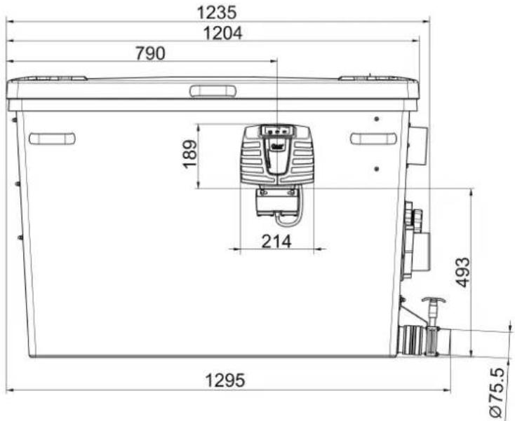
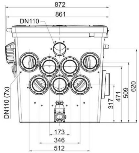
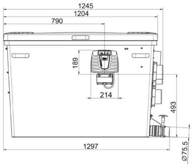
| Dimensions | Length | mm | 1295 | 1295 |
| Width | mm | 861 | 861 | |
| Height | mm | 821 | 821 | |
| Weight | Without water | kg | 125 | 125 |
| With water | kg | 535 | 655 | |
| Rinsing pump | Water pressure | bar | 7 | 7 |
| Water consumption per rinsing cycle | l | 3.2 | 3.2 | |
| Drum | Diameter | mm | 565 | 565 |
| Width | mm | 780 | 780 | |
| Screen elements | Quantity | 16 | 16 | |
| DN 110 inlet | Quantity | 2 | 7 | |
| G2 inlet | Quantity | 3 | - | |
| Connection hose (diameter) | mm | 50 mm | - | |
| DN 180 outlet | Quantity | 2 | 2 | |
| Dirt outlet | Quantity | 2 | 2 | |
| Connection | DN 75 / DN 110 | DN 75 / DN 110 | ||
| Circulation capa-city | minimum | l/h | 25000 | 25000 |
| Max. | l/h | 50000 | 66000 | |
| Container including container cover above water level of pond | mm | - | 140 | |
| Permissible tolerance of the water level in the pond | mm | - | -20 | |
| Permissible frictional losses in supply lines | mbar (cm) | - | 7 (7) | |
| The minimum required friction losses in the pipes for using the status detection of the filter pump | mbar (cm) | - | 3.5 (3.5) | |
| ProfiClear Premium power pack | |||
| Rated voltage | V AC | 230 | |
| Mains frequency | Hz | 50 | |
| Output voltage | V DC | 12 | |
| Power consumption | in idle state | W | 5 |
| during cleaning | W | 75 | |
| Max. output current | A | 8.3 | |
| Length of power cable | m | 2 | |
| Length of connection cable to control system | m | 0.4 | |
| Dimensions | Length | mm | 231 |
| Width | mm | 148 | |
| Height | mm | 63 | |
14 Symbols on the unit
 | [8Kxz] | Dust tight. Watertight to 20 m depth. |
| [TGkz] | Dust protected. Protected against water splashed from all directions. | |
| [y7xz] | Safety fuse16 A / 250 V, slow-blow fuse | |
 | Possible hazard for persons wearing pace makers! | |
 | Protect from direct sunlight | |
| [w368] | Remove the unit at freezing temperatures! | |
 | Do not reach into the inlet or outlet. Risk of injury due to shearing movement. | |
| [w43w] | Read the instructions for use. |
Raccordement 50 mm (G2)
5.1 Pumpet system 211
- ProfiClear Premium TF-XL
- WARNING
- Table of Contents
- Information about these operating instructions....55
- Safety information 56
- Product Description....57
- Installation and connection....60
- Commissioning/start-up 65
- Operation....70
- Information about these operating instructions
- Warnings used in these instructions
- NOTE
- TIP
- Cross-references used in these instructions
- Safety information
- Electrical connection
- Danger for persons with pacemakers
- Safe operation
- Product Description
- Scope of delivery
- Unit configuration
- Function description
- Pump fed system
- Advantages of the pump fed system:
- Gravity fed system
- Advantages of the gravity fed system:
- Easy Garden Control System (EGC)
- Intended use
- Installation and connection
- Fitting the filter container
- CAUTION
- Pump-fed system
- Gravity fed system
- Connecting the drum filter
- Information regarding pipes
- Connecting the inlet of the pump-fed system
- Installing a UVC clarifier
- mm (G2) connection
- Connecting the inlet of the gravity-fed system
- Connecting the dirt outlet
- Connecting the control system
- Connecting the power pack
- Connecting the EGC box
- Installing the control system with EGC box
- Pump fed system
- Gravity fed system
- Commissioning/start-up
- Pump-fed system
- Order of starting up steps
- Setting the level detection device
- Gravity-fed system
- Order of starting up steps
- Setting the level detection device
- □ R
- Setting the filter pump status detection
- Operation
- Control system overview
- Display
- On|Off button, Quit Error
- LED, 2 colours
- Menu button
- Clean button
- Blue LED
- Switching ON/OFF
- Operating modes
- Manual cleaning
- Settings in the menus
- CL: Cleaning time "Cleaning"
- EC: Extended cleaning time "Extra Cleaning"
- IE: Interval of the extended cleaning time "Interval Extra Cleaning"
- E7: Pump status detection
- Reading out the number of cleaning cycles
- Cleaning cycles in 24 hours
- Total cleaning cycles
- Loading default settings
- System messages
- EN
- Maintenance and cleaning
- Cleaning the device
- Regular tasks
- Regular checks
- Removing accumulated dirt
- Cleaning the entire filter system
- How to proceed:
- Cleaning the rinsing device
- Cleaning the screen elements
- Removing the screen element
- Removing
- Fitting
- Decalcifying the screen elements
- Removing the filter drum
- Installing the filter drum
- Cleaning the rinsing pump
- Replacing the rinsing pump
- Storage/winter protection
- Wear parts
- Disposal
- Spare parts
- Symbols on the unit
- Raccordement 50 mm (G2)
Brand : OASE
Model : ProfiClear Premium TF-XL
Category : Water filter