DEH CRAWL SPACE 70 - Dehumidifier MSW - Free user manual and instructions
Find the device manual for free DEH CRAWL SPACE 70 MSW in PDF.

| Product type | Dehumidifier |
| Brand | MSW |
| Model | DEH CRAWL SPACE 70 |
| Rated voltage / frequency | 230 V~ / 50 Hz |
| Rated power | 280 W (at 30°C, 80% RH) |
| Dehumidification capacity | 45 L/day (30°C, 80% RH) / 26 L/day (27°C, 60% RH) |
| Rated input current | 1.7 A |
| Maximum input current | 2.5 A (38°C, 80% RH) |
| Sound pressure level | ≤55 dB(A) |
| Refrigerant | R290, charge 150 g |
| Dimensions (L x D x H) | 330 x 605 x 380 mm |
| Weight | 23.5 kg |
| Functions | Dehumidification, ventilation, auto defrost, timer (0-23 h) |
| Humidity setting range | 10% to 99% RH |
| Display | Indicator lights (power, defrost, dehumidification, ventilation, timer) |
| Remote control | Optional: wall controller (CAT5 cable) or remote control |
| Drainage type | Continuous drainage via hose (included) |
| Filter | Removable mesh filter, replace every 1500 hours |
| Maintenance | Clean the body with a damp cloth (no soap); vacuum or replace the filter |
| Safety | Compressor start delay (3 min); automatic shutdown on error (codes E1-E4); do not tilt >45° |
| Installation | On flat, vertical surface; free space 12\" (31 cm) at inlet and 36\" (92 cm) at outlet; vapor barrier required |
Frequently Asked Questions - DEH CRAWL SPACE 70 MSW
User questions about DEH CRAWL SPACE 70 MSW
0 question about this device. Answer the ones you know or ask your own.
Ask a new question about this device
Download the instructions for your Dehumidifier in PDF format for free! Find your manual DEH CRAWL SPACE 70 - MSW and take your electronic device back in hand. On this page are published all the documents necessary for the use of your device. DEH CRAWL SPACE 70 by MSW.
USER MANUAL DEH CRAWL SPACE 70 MSW
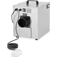
1 - Griffe
2 - Lufteinlass
3 - Filtersieb
4 - Füße
5 - Luftauslass
MSW-DEH CRAWL SPACE 90 MSW-DEH CRAWL SPACE 120


natural_image
Line drawings of four different household appliances: a front-mounted heater, a front-mounted air vent, a front-mounted fan, and a vacuum cleaner (no text or symbols present)natural_image
Technical line drawings of four different household appliances or enclosures, including a vacuum cleaner and fan-shaped device (no text or symbols present)This User Manual has been translated for your convenience using machine translation. Reasonable efforts have been made to provide an accurate translation; however, no automated translation is perfect nor is it intended to replace human translators. The official User Manual is the English version. Any discrepancies or differences created in the translation are not binding and have no legal effect for compliance or enforcement purposes. If any questions arise related to the accuracy of the information contained in the User Manual, please refer to the English version of those contents which is the official version.
Technical data
| Parameter description | Parameter value | ||
| Product name | Air Dehumidifier | ||
| Model | MSW-DEH CRAWL SPACE 70 | MSW-DEH CRAWL SPACE 90 | MSW-DEH CRAWL SPACE 120 |
| Rated voltage [V~] / frequency [Hz] | 230/50 | ||
| Rated power [W] | 280 (30°C, 80%RH) | 620 (30°C, 80%RH) | 820 (30°C, 80%RH) |
| Rated Capacity [L/day] | 45 (30°C, 80%RH)26 (27°C, 60%RH) | 72 (30°C, 80%RH)43 (27°C, 60%RH) | 90 (30°C, 80%RH)55 (27°C, 60%RH) |
| Rated Input Current [A] | 1.7 (30°C, 80%RH) | 2.7 (30°C, 80%RH) | 3.7 (30°C, 80%RH) |
| Max Rated Input Current [A] | 2.5 (38°C, 80%RH) | 3.7 (38°C, 80%RH) | 5.4 (38°C, 80%RH) |
| Sound Pressure Level [dB(A)] | ≤55 | ≤55 | ≤55 |
| Max Refrigerant Charge | R290/150g | R290/270 | R290/330 |
| Max Suction / Exhaust Side Working Pressure [MPa] | 2.8 / 0.8 2.8 / 0.8 2.8 / 0.8 | ||
| Heat Exchanger Max Allowable Pressure [MPa] | 2.8 | 2.8 | 2.8 |
| Dimensions [width x depth x height; mm] | 330 x 605 x 380 | 360 x 560 x 410 | 380 x 600 x 500 |
| Weight [kg] | 23.5 | 28.5 | 33 |
Installation Requirements
The area where the dehumidifier is located should be sealed with a vapor barrier.
If the unit is installed in a crawl space, all vents should be sealed.
For the best air diffusion, install the unit so that a side panel faces the wall.
For proper ventilation, neither the inlet nor discharge should be positioned against a wall. The inlet needs a minimum of 12" (\~31 cm) clearance and the discharge require a minimum of 36" (\~92 cm) clearance.
The dehumidifiers are only intended for operation when the unit is upright and level with the feet on the ground.
Installation
- Place your dehumidifier on a flat surface.
- Avoid putting it against a vapor barrier. Don't use anything to support it at the base. Place it on the floor. If your device was place in any other position other than upright place it upright and allow two hours before turning it on.
-
Arrange the line of drainage
-
Route the drain hose to a suitable drainage outside.
-
There should not be any loops or dips on the drainage hose.
-
Seal of the point where the dehumidifier is located using a vapor barrier.
- Seal off all openings if the unit is installed in a crawl space.
- Avoid placing the inlet and outlet against a wall. This ensures proper ventilation. You need to give a 12" (\~31 cm) allowance of space with the inlet and 36" (\~92 cm) clearance for the discharge.
- Place the side panel facing the wall so that the dehumidifier delivers the best diffusion.
- Your dehumidifier is designed to be placed on the ground at the same level with the feet. Place it upright.
- Maintenance should be conducted with the power switched off or unplugged.
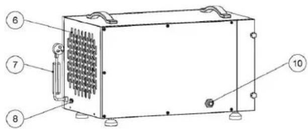
MSW-DEH CRAWL SPACE 70
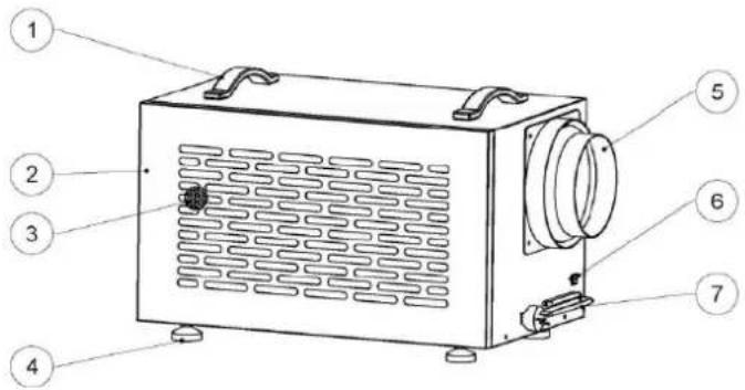
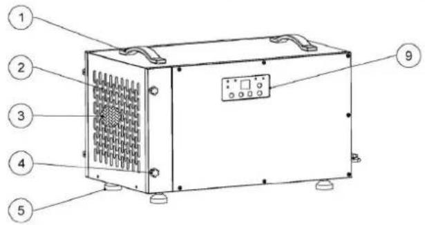
1 - Handles
2-Air inlet
3 - Filter screen
4 - Feet
5 - Air outlet
6 - Controller cable socket
7 - Power cord
8 - Drainage
9 - Display / screen
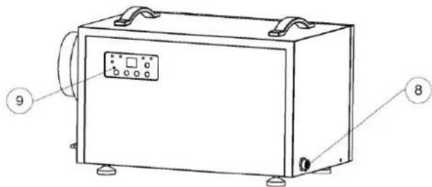
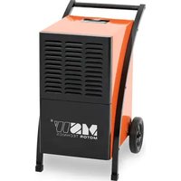
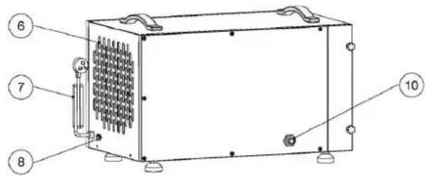
MSW-DEH CRAWL SPACE 90 MSW-DEH CRAWL SPACE 120

1 - Handles
2-Air inlet
3 - Filter screen
4 - Door buckle
5 - Feet
6 - Air outlet
7 - Power cord
8 - Controller cable socket
9 - Display / screen
10 – Drainage
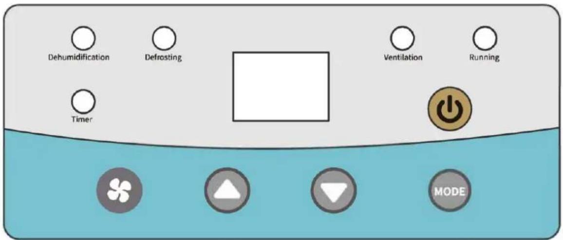
Keys and Display Symbols

Functions of Keys:

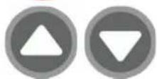
Use this button to turn the dehumidifier on and off.
Please note that there is a 1-minute fan delay.

Use the up and down arrows to set the desired humidity set point on the display screen or timing shutdown time.
When set desired humidity set point, the set point can be any number between 10%-99%.
When set timing shutdown time, the set point can be 00-23.
Each short press of the setting button: Set humidity value, set dehumidification/ventilation mode, set timing on/off time, and exit.
Function Description:
Adjust the wind speed: short press the wind speed button to adjust.
Adjust the set humidity value: short press the mode button, the position of the humidity set value will flash, press the up and down keys to adjust.
Ventilation/dehumidification mode setting: Short press the M key twice, press the up and down keys to switch modes.
Set the delay switch time: short press the mode button 3 times to enter the delayed power-on time (display on) setting, press the up and down keys to adjust, short press the mode key 4 times to enter the delayed power-off time (display off) setting, press Up and down keys to adjust.
Remote Control Instructions (Optional)
Dehumidifiers can be controlled using optional remote accessories:
Option 1. Wall mounted controller connecting 25'CAT 5 cable.
Option 2. Remote control.
If your dehumidifier is installed in your crawl space, the wall mounted controller could be mounted in your living space or garage. This provides you with an easy way to monitor the dehumidifier. So as the remote control, you can operate the device in a distance.
Wall Mounted Controller View
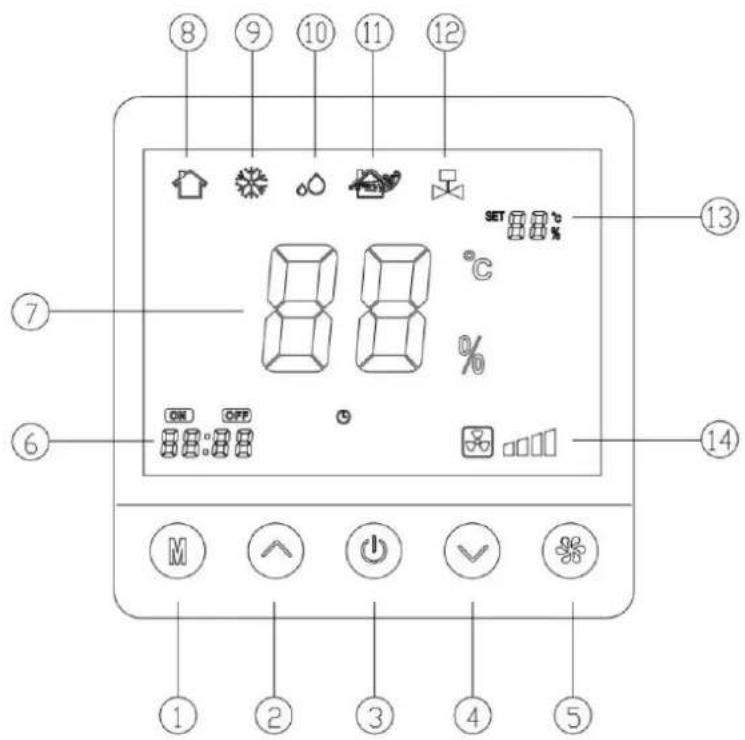
1 - M key (Mode Key)
2 - Up key
3 - Power key
4 - Down key
5 – Wind speed key
6 - Delay switch display area
7 – Ambient humidity display area
8 - Boot icon
9 - Defrost icon
10 - Dehumidification icon
11 - Ventilation icon
12 – Water pump on icon
13 – Set the humidity display area
14 – Fan speed display area
Remote Control View
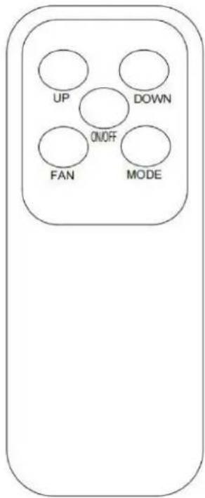
Remote control operates in the same way as on-device controllers and wall mounted controller.
Automatic Defrosting Function
At low temperatures the device will start defrosting automatically. During this period the cooling fan works properly but the inserted compressor switches itself off. The Defrosting indicator light will illuminate red.
Maintenance
WARNING: Always unplug the unit before doing any maintenance.
Cleaning the Machine Body
- Use a soft, damp cloth to clean the exterior of unit. Do not use any soap or solvents.
MSW-DEH CRAWL SPACE 70
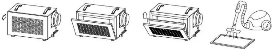
Filter replacement
natural_image
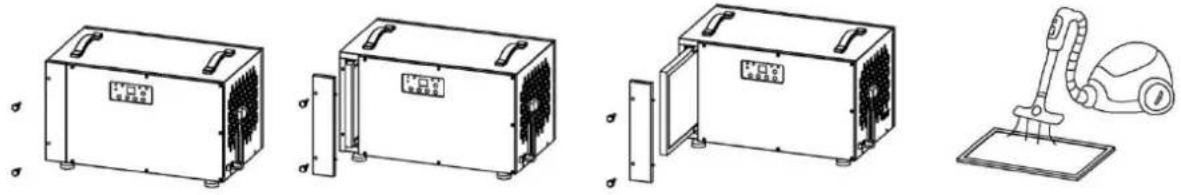
Line drawings of four different household appliances: a front-mounted air purifier, a front-mounted fan unit, a front-mounted vacuum cleaner, and a hand washing machine (no text or symbols present)- Unplug the unit.
- The air inlet plate is held by a magnet, open the air inlet plate as shown in the picture and take out the filter.
- Please vacuum or replace the filter.
Filter needs changed every 1500 hours of use.
MSW-DEH CRAWL SPACE 90 MSW-DEH CRAWL SPACE 120
Filter replacement
- Unplug the unit.
- Unscrew the two hand-twist locks counterclockwise.
- Remove the filter cover.
- Pull out the filter.
- Please vacuum or replace the filter.
Filter needs changed every 1500 hours of use.
Important Instructions
- The compressor turns itself on three minutes after turning on the dehumidifier.
- When the device defrosts the cooling fan works properly but the inserted compressor switches itself off.
• Filter needs changed every 1500 hours of use. - Leave a safe distance between wall and air in- and outlets.
- Unplug the device and attach the mains plug to the product if it is not in use over a longer period.
- Don't tilt the device more than 45^ , neither when moving nor when operating.
- If the dehumidifier was tilted by accident, don't use it for a period of 12 hours.
Error Messages
If an error occurs, display will show the respective code:
| ERROR | REASON | SOLUTION |
| E1 | Coil Sensor-Error | Exchange the coil sensor |
| E2 | Moisture Sensor-Error | Exchange the moisture sensor |
| E3 | Temperature Sensor-Error | Exchange the temperature sensor |
Troubleshooting
| Problem | Description | Solution |
| Dehumidifier does not work. | 1. Device has no power.2. Mains plug is not plugged in properly.3. Display shows error code E4. | 1. Turn on the power supply.2. Connect the mains plug properly.3. Empty the water collection container. |
| Bad Dehumidification Performance | 1. Air in- or outlet is covered.2. Room is not closed. Low moisture and temperature. | 1. Uncover Air in- and outlet.2. Close all doors and windows.3. The lower the room temperature the worse the dehumidification performance. |
| High Noise Level | 1. Device was not put on even ground.2. Air in- or outlet is covered | 1. Position the device on even ground.2. Uncover Air in- and outlet. |

MSW-DEH CRAWL SPACE 90 MSW-DEH CRAWL SPACE 120


natural_image
Three circular icons: a red 'Power' button, two gray triangles with white and gray fill, no text or symbols present.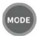
MSW-DEH CRAWL SPACE 90 MSW-DEH CRAWL SPACE 120

MSW-DEH CRAWL SPACE 90 MSW-DEH CRAWL SPACE 120


natural_image
Three circular icons: a red 'Power' button, two gray triangles with white and gray fill, no text or symbols present.
1 - Touche M (touche mode)
2 - Touche haut
natural_image
Line drawings of four different household appliances: a front-mounted air purifier, a front-mounted fan, a front-mounted washing machine, and a vacuum cleaner (no text or symbols present)natural_image
Technical line drawings of four different household appliances or enclosures, including a vacuum cleaner and fan-shaped device (no text or symbols present)MSW-DEH CRAWL SPACE 90 MSW-DEH CRAWL SPACE 120


natural_image
Three circular icons: a red 'Power' button, two gray triangles with white and gray fill, no text or symbols present.natural_image
Line drawings of four different household appliances: a front-mounted air conditioner, a front-mounted fan, a front-mounted device with a cloth cover, and a vacuum cleaner (no text or symbols present)natural_image
Technical line drawings of four different household appliances or enclosures, including a vacuum cleaner and fan assembly (no text or symbols present)MSW-DEH CRAWL SPACE 90 MSW-DEH CRAWL SPACE 120


natural_image
Line drawings of four different household appliances: a front-mounted air purifier, a portable air conditioner unit, a flat-screen vacuum cleaner, and a hand washing machine (no text or symbols present)natural_image
Technical line drawings of four different household air purifiers with mounting brackets and a vacuum cleaner (no text or symbols)MSW-DEH CRAWL SPACE 90 MSW-DEH CRAWL SPACE 120

Taster og displaysymboler

natural_image
Three circular icons: a red circle with a white power button, two gray circles with white and gray triangles (no text or symbols)MSW-DEH CRAWL SPACE 90 MSW-DEH CRAWL SPACE 120
MSW-DEH CRAWL SPACE 90 MSW-DEH CRAWL SPACE 120

natural_image
Three circular icons: a red 'Power' button, two gray triangles with white and gray fill, no text or symbols present.
natural_image
Line drawings of four different household appliances: a front-mounted air vent, a front-mounted fan, a front-mounted device with a cloth handle, and a vacuum cleaner (no text or symbols present)natural_image
Technical line drawings of four different household appliances or enclosures, including a vacuum cleaner and fan-shaped device (no text or symbols present)MSW-DEH CRAWL SPACE 90 MSW-DEH CRAWL SPACE 120

Taster og displaysymboler

1 - Handtag
2 - Luftintag
3 – Filterskärm
4 - Fötter
5 - Luftutlopp
6 – Styrkabeluttag
7 - Nätsladd
8 – Dränering
9 – Display / skärm

MSW-DEH CRAWL SPACE 90 MSW-DEH CRAWL SPACE 120
1 - Handtag
2 - Luftintag
3 – Filterskärm
4 – Dörrspänne
5 – Fötter
6 – Luftutlopp
7 – Nätsladd
8 – Styrkabeluttag
9 – Display / skärm
10 – Dränering

natural_image
Line drawing of a portable electronic device with a textured grille and control buttons (no text or symbols)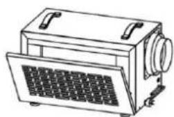
natural_image
Line drawing of a vintage portable radio with ventilation grilles and control knobs (no text or symbols)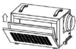
natural_image
Line drawing of a mechanical device with a grid-patterned base and directional arrows indicating motion (no text or symbols)
natural_image
Line drawing of a vacuum cleaner next to a flat surface (no text or symbols)natural_image
Technical line drawings of four different household air purifiers and a vacuum cleaner (no text or symbols present)MSW-DEH CRAWL SPACE 90 MSW-DEH CRAWL SPACE 120

natural_image
Three circular icons: a red 'Power' button, two gray downward-pointing triangles, and one white triangle (no text or symbols)
natural_image
Line drawings of four different household appliances: a front-mounted air vent, a front-mounted fan, a front-mounted device with a cloth handle, and a vacuum cleaner (no text or symbols present)natural_image
Technical line drawings of four different household appliances with no visible text or symbolsMSW-DEH CRAWL SPACE 90 MSW-DEH CRAWL SPACE 120

natural_image
Line drawings of four different household appliances: a front-mounted air purifier, a portable air conditioner, a flat-screen vacuum cleaner, and a hand washing machine (no text or symbols present)natural_image
Line drawings of four different household appliances or enclosures, including a vacuum cleaner and fan-shaped device (no text or symbols present)MSW-DEH CRAWL SPACE 90 MSW-DEH CRAWL SPACE 120


MSW-DEH CRAWL SPACE 90 MSW-DEH CRAWL SPACE 120


natural_image
Three circular icons: a red 'Power' button, two gray triangles with white and gray fill, no text or symbols present.1 - Ručke
2 - Ulaz zraka
3 - Zaslon filtera
4 - Stopala
5 - Izlaz zraka
6 – Utičnica kabela kontrolera
7 – Kabel za napajanje
8 - Drenaža
9 - Zaslon / ekran

MSW-DEH CRAWL SPACE 90 MSW-DEH CRAWL SPACE 120

1 – Ručke
2 – Ulaz zraka
3 – Zaslon filtera
4 – Kopča za vrata
5 - Stopala
6 - Izlaz zraka
7 – Kabel za napajanje
8 – Utičnica kabela kontrolera
9 – Zaslon / ekran
10 – Drenaža

Tipke i simboli na zaslonu

Funkcije tipki:


Koristite ovaj gumb za uključivanje i isključivanje odvlaživača.
Imajte na umu da postoji 1-minutna odgoda ventilatora.
1 - tipka M (tipka načina)
2 - tipka gore
3 – Tipka za napajanje
4 – Tipka prema dolje

1 - rankenos
2 – Oro jleidimo anga
3 - filtro ekranas
4 - pèdos
5 – Oro išleidimo anga
6 – Valdiklio kabelio lizdas
7 - maitinimo laidas
8 – Drenažas
9 - Ekranas / ekranas
MSW-DEH CRAWL SPACE 90 MSW-DEH CRAWL SPACE 120

natural_image
Three circular icons: a red 'Power' button, two gray triangles with white and gray fill, no text or symbols present.
natural_image
Line drawings of four different household appliances: a front-mounted air purifier, a front-mounted fan, a front-mounted heater, and a vacuum cleaner (no text or symbols present)natural_image
Technical line drawings of four different household appliances or enclosures, including a vacuum cleaner and fan assembly (no text or symbols present)MSW-DEH CRAWL SPACE 90 MSW-DEH CRAWL SPACE 120


natural_image
Three circular icons: a red 'Power' button, two gray triangles with white and gray fill, no text or symbols present.
natural_image
Line drawings of four different household appliances: a front-mounted air vent, a front-mounted fan, a front-mounted device with a cloth handle, and a vacuum cleaner (no text or symbols present)natural_image
Technical line drawings of four different household appliances or enclosures, including a vacuum cleaner and fan-shaped device (no text or symbols present)MSW-DEH CRAWL SPACE 90 MSW-DEH CRAWL SPACE 120

1 - Ročaji
2 - Dovod zraka
3 - Zaslon filtra
4 – Zaponka na vratih
5 - Stopala
6 - Izhod zraka
7 – Napajalni kabel
8 – Vtičnica kabla krmilnika
9 – Prikaz/zaslon
10 - Drenaža

Tipke in simboli na zaslonu
Funkcije tipk:
natural_image
Three circular icons: a red 'Power' button, two gray triangles with white and gray fill, no text or symbols present.
S tem gumbom vklopite in izklopite razvlaževalec.
1 - tipka M (tipka načina)
2 - Tipka gor
3 - Tipka za vklop
4 - Tipka navzdol
natural_image
Line drawings of four different household appliances: a front-mounted air purifier, a front-mounted fan, a front-mounted heater, and a vacuum cleaner (no text or symbols present)natural_image
Technical line drawings of four different household appliances or enclosures, including a vacuum cleaner and fan assembly (no text or symbols present)- Odklopite enoto.
- Odvijte obe ročni zasučni ključavnici v nasprotni smeri urinega kazalca.
- Odstranite pokrov filtra.
- Izvlecite filter.
- Posesajte ali zamenjajte filter.
For the disposal of the device please consider and act according to the national and local rules and regulations.
CONTACT
expondo Polska sp. z o.o. sp. k.