MD32- LASER - Drill MSW - Free user manual and instructions
Find the device manual for free MD32- LASER MSW in PDF.

User questions about MD32- LASER MSW
0 question about this device. Answer the ones you know or ask your own.
Ask a new question about this device
Download the instructions for your Drill in PDF format for free! Find your manual MD32- LASER - MSW and take your electronic device back in hand. On this page are published all the documents necessary for the use of your device. MD32- LASER by MSW.
USER MANUAL MD32- LASER MSW
Modelle MSW-MD32-ECO/MSW-MD32-PRO/MSW-MD60-ECO/MSW-MD60-PRO:

A - Rotationen:
- L-links;
• R – rechts; - 0 – Neutralstellung
natural_image
Top-down view of a gray cylindrical object with four cross-shaped arrows pointing inward, no text or symbols present.natural_image
Close-up of mechanical components with metallic and brass parts, no visible text or symbolsnatural_image
Close-up of a metallic mechanical component with two black arrows pointing to features, against a red background (no text or symbols visible)natural_image
Two mechanical components with arrows indicating direction of movement, no visible text or symbolsnatural_image
Two experimental setups showing mechanical components with arrows indicating motion direction (no text or symbols present)This User Manual has been translated for your convenience using machine translation. Reasonable efforts have been made to provide an accurate translation; however, no automated translation is perfect nor is it intended to replace human translators. The official User Manual is the English version. Any discrepancies or differences created in the translation are not binding and have no legal effect for compliance or enforcement purposes. If any questions arise related to the accuracy of the information contained in the User Manual, please refer to the English version of those contents which is the official version.
I. Technical data
| Parameter description Parameter value | ||||
| Product name | Magnetic Drill | |||
| Model | MSW-MD32-ECO | MSW-MD32-PRO | MSW-MD60-ECO | MSW-MD60-PRO |
| Rated voltage [V~] / frequency [Hz] | 230/50 | |||
| Rated power [W] | 1380 | 1680 | ||
| Capacity of the small cooling tank [ml] | 300 | |||
| Rotational speed without load [rpm] | 600 | 370 | ||
| Maximum attraction [N] | 18000 | |||
| Screw tap diameter | M14 | M25 | ||
| Diameter of lace drill [mm] | 35 | 60 | ||
| Drill diameter [mm] | 19 | 28 | ||
| Dimensions (width x depth x height) [mm] | 31x21.5x56.5 | 30x21.5x56.5 | 32x22x56.5 | 22.5x32x57 |
| Weight [kg] | 16.8 | 16.8 | 16.32 | 17.35 |
| Parameter description Parameter value | ||||
| Product name | MAGNETIC DRILL WITH LASER | |||
| Model | MSW-MD32-LASER | MSW-MD32-LASER PRO | MSW-MD60-LASER | MSW-MD60-LASER PRO |
| Rated voltage [V~] / frequency [Hz] | 230/50 | |||
| Rated power [W] | 1300 | 1680 | ||
| Capacity of the small cooling tank [ml] | 300 | |||
| Rotational speed without load [rpm] | 100-475 | 100-395 | ||
| Maximum attraction [N] | 18000 | |||
| Screw tap diameter | M14 | M25 | ||
| Diameter of lace drill [mm] | 35 | 60 | ||
| Drill diameter [mm] | 19 | 28 | ||
| Dimensions (width x depth x height) [mm] | 33.5x28x56 | 34x28x57 | 33x28x57 | 33x28x54 |
| Weight [kg] | 17.1 | 17.8 | 19 | 18.65 |
II. General description
The user manual is designed to assist in the safe and trouble-free use of the device. The product is designed and manufactured in accordance with strict technical guidelines, using state-of-the-art technologies and components. Additionally, it is produced in compliance with the most stringent quality standards.
DO NOT USE THE DEVICE UNLESS YOU HAVE THOROUGHLY READ AND UNDERSTOOD THIS USER MANUAL.
To increase the product life of the device and to ensure trouble-free operation, use it in accordance with this user manual and regularly perform maintenance tasks. The technical data and specifications in this user manual are up to date. The manufacturer reserves the right to make changes associated with quality improvement. The device is designed to reduce noise emission risks to a minimum, taking into account technological progress and noise reduction opportunities.
Legend

The product satisfies the relevant safety standards.

Read instructions before use.
The product must be recycled.

WARNING! or CAUTION! or REMEMBER! Applicable to the given situation. (general warning sign)

Use ear protection. Exposure to loud noise may result in hearing loss.

Wear protective goggles.

Wear a dust mask (respiratory tract protection).

Wear protective gloves.

Wear foot protection.

Class II protection device with double insulation.
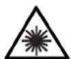
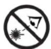
NOTE: Laser beam. It is forbidden to look at the laser light. (for the MSW-MD32-Laser, MSW-MD32-Laser PRO, MSW-MD60-Laser, MSW-MD32-Laser PRO models)

PLEASE NOTE! Drawings in this manual are for illustration purposes only and in some details may differ from the actual product.
III. Usage safety

ATTENTION! Read all safety warnings and all instructions. Failure to follow the warnings and instructions may result in electric shock, fire and/or serious injury or even death.
The terms "device" or "product" are used in the warnings and instructions to refer to: Magnetic Drill / Magnetic Drill with laser
Safety instructions
-
Keep the work area clean. Cluttered areas can cause injuries.
-
Consider the work area environment before starting to work. Don't expose power tools to rain or wet soil. Don't use power tools in damp or wet locations. The work area should be well secured. Don't use the tool in the presence of flammable liquids or gases. Power tools produce sparks during normal operation or when switching ON/OFF. Never use power tools in dangerous sites containing lacquer, paint, benzene, thinner, gasoline, gases, adhesive agents, and other materials which are combustible or explosive.
-
Provide sufficient protection against electric shock. Prevent body contact with grounded surfaces. For example: pipes, radiators, ranges, refrigerator enclosures.
-
Keep children and third parties away from the work area.
-
Store unused tools. When not in use, tools should be stored in dry and high or locked-up place out of the reach of children.
-
Do not overload the machine! To ensure an optimum performance and safety of the machine, only use it within the set parameters.
-
Use only suitable tools. Don't use small tools or attachments. Don't use tools for not intended purposes. For example: don't use circular saws for cutting tree limbs or logs.
-
Dress appropriately. Do not wear loose clothing or jewellery. They can get caught in the moving parts. Rubber gloves and non-skid footwear are recommended when working outdoors. Wear protective hair covering to contain long hair.
-
Use safety glasses. Also use face or dust mask if the cutting operation is dusty.
-
Do not damage the connection cable. Never carry the tool by the cord or yank the cord to disconnect it from the power source. Keep the cord away from heat and oil sources and sharp edges.
-
Secure the work area. It is recommended to use clamps or a vice for fixation. Please pay special attention to your hands when operating the machine.
-
Do not overreach yourself. Keep proper footing and balance at all times.
-
Hold the machine firmly with both hands. When using the machine, hold it by the handles provided with the machine.
-
Maintain tools with care. Keep tools clean for a better and safer performance. Follow the instructions for changing accessories. Inspect the extension cords periodically and replace if damaged. Keep handles dry, clean, and free from oil and grease.
-
Switch off the machine and disconnect the cable before performing maintenance or changing accessories.
-
Remove adjusting keys and wrenches. Always make sure that keys and adjusting wrenches are removed from the tool before turning it on.
-
Avoid unintentional starting. Don't carry a plugged-in tool with your fingers on the switch. Be sure the tool is switched off when plugging it in.
-
During outdoor work use extension cords intended for outdoor use.
-
Stay alert when operating the machine. Do not operate the tool when you are tired.
-
Check damaged parts. Before further use of the tool, any part of the casing or other parts that are damaged should be carefully checked to determine if they will operate properly and perform their intended function. Check for alignment of moving parts, mounting, and any other conditions that
may affect its operation. A damaged part should be properly repaired or replaced by an authorized service centre unless otherwise indicated elsewhere in this instruction manual. Defective switches should be replaced by an authorized service centre. Do not use the tool if the switch does not turn it on and off.
-
Do not use power tools for applications other than those specified in the instructions (other than that for which it was designed).
-
To ensure the designed operational integrity of power tools, do not remove installed covers or screws.
-
Do not touch movable parts or accessories unless the power source has been disconnected.
-
Use your tool at a lower input load than specified on the nameplate to increase working efficiency and decrease the wearing out process.
-
Do not wipe any plastic parts with solvents. Solvents such as gasoline, thinner, benzene, alcohol, ammonia and oil may damage and crack the plastic parts. Do not wipe them with such solvents. Wipe the plastic parts with a soft cloth lightly dampened with soapy water.
-
Consult an authorized service agent in the event of power tool failure.
-
Use only original replacement parts.
-
This tool should only be disassembled for replacement of carbon brushes.
-
For transporting and moving magnetic drills from storage to the place of use, it is necessary to take into account the health and safety rules during manual transport works that are in force in the country where the demolition hammers are used.
-
It is not allowed to climb onto the machine.
Precautions on using the machine
-
Wear protective glasses to protect your eyes.
-
Use dust masks.
-
Use earplugs to keep your ears noise-free while working.
-
Check for the proper handle adjustment.
-
The tool becomes very hot during operation.
-
Safe operation depends on one's work posture.
-
When working in an elevated location, pay attention to objects and persons below.
-
Wear protective shoes to protect your feet.

ATTENTION! Despite the safe design of the device and its protective features, and despite the use of additional elements protecting the operator, there is still a slight risk of accident or injury when using the device. Stay alert and use common sense when using the device.
IV. Scope of usage
Magnetic drills are designed for precise drilling in ferromagnetic materials. Drilling can take place in a vertical or horizontal position, as well as above the head.
NOTE! It should be remembered that a suitable surface and thickness (minimum 10mm) of ferromagnetic material must be available during operation.
The user is liable for any damage resulting from unintended use of the device.
V. Before first use
1. Power source:
Ensure that the power source which is utilized conforms to the power requirements specified on the product name.
2. Power switch:
Ensure that the power switch is in the OFF position.
If the plug is connected to a power receptacle while the power switch is in the ON position, serious accidents can occur.
3. Extension cord:
When the work area has no power source, use an extension cord of sufficient thickness and rated capacity. The extension cord should be kept as short as possible.
4. Mounting tools in the device:
In order to mount the drill in the spindle, unscrew the drill chuck using the drill chuck key, insert the drill into the spindle and then tighten the spindle with the drilling key.
VI. Description of the device
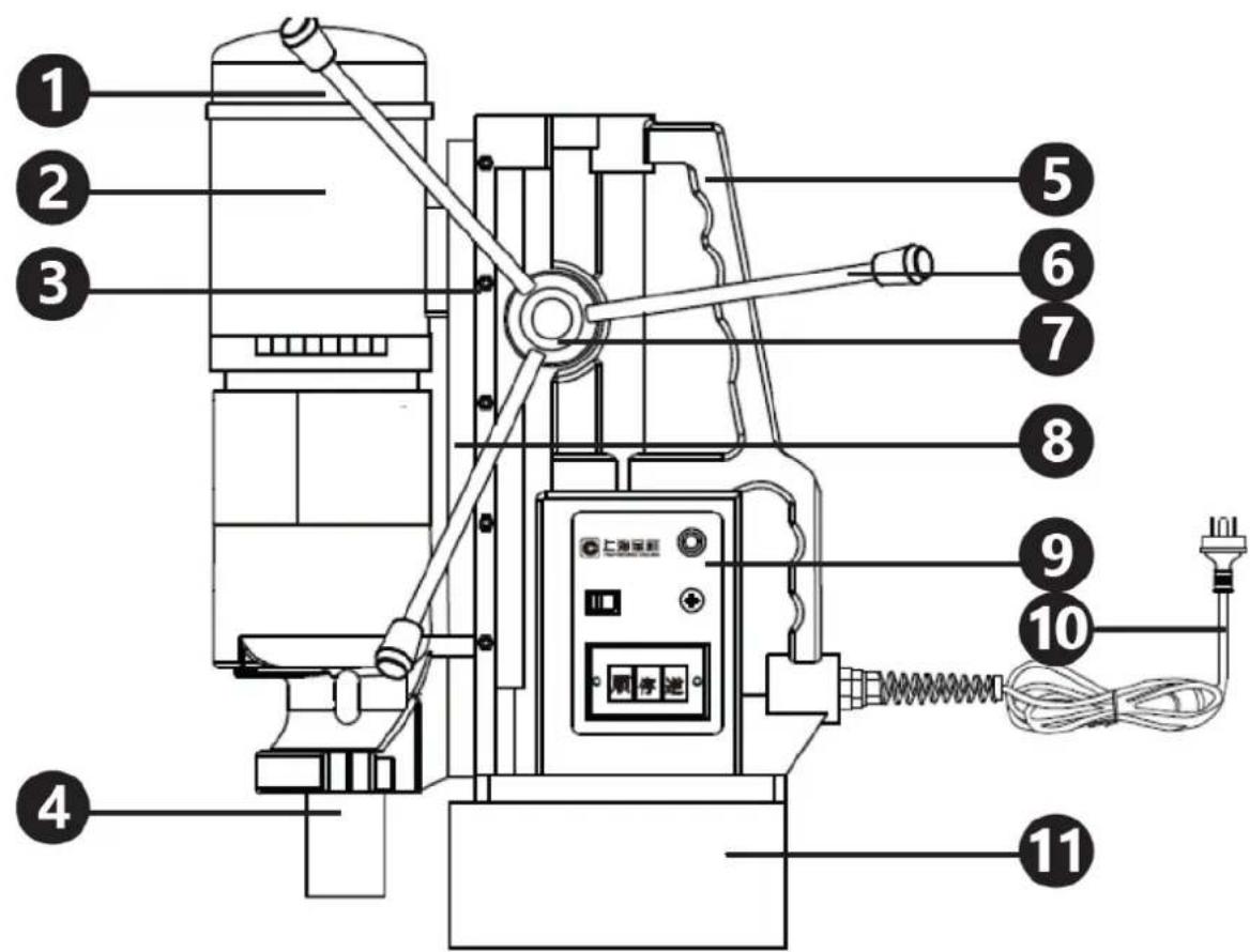
1 - air inlet/cover of engine carbon brushes
2 - engine
3 - fixing screws
4 - spindle
5 - console/transport handle
6 - handles for adjusting the height of the drill
7 - lever for raising/lowering the device
8 - rail
9 - control panel
10 - power cord
11 - magnet
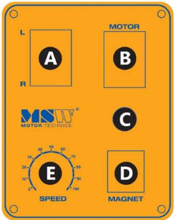
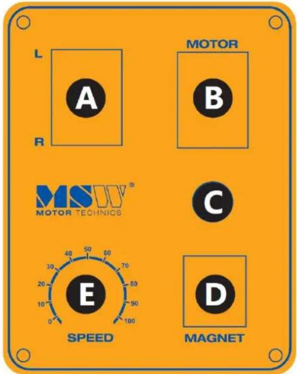
VII. Description of control panels:
Models MSW-MD32-ECO/MSW-MD32-PRO/MSW-MD60-ECO/MSW-MD60-PRO:

A - rotations:
- L-left;
• R - right; - 0 – neutral position
B - drill motor switch:
• I – switching on the device;
• 0 – switching off the device
C - fuse
D - magnet switch:
- I – active magnet;
- 0-magnet inactive
E - drill rotation speed controller
VIII. How to use laser function
NOTE: This chapter applies only to following models:
- MSW-MD32-LASER
MSW-MD32-LASER PRO - MSW-MD60-LASER
MSW-MD60-LASER PRO
Steps:
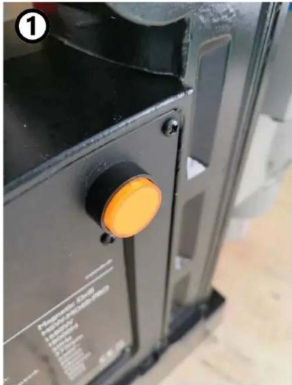
1) Turn on the laser using the button on the side of the machine's housing.
2) Ensure that the direction of the laser beam aligns with the drilling location.
3) Lower the drill head and begin drilling.

natural_image
Close-up of a black mechanical clamp or bracket component with a bolt, mounted on a metal frame (no visible text or symbols)IX. How to use the magnetic drill
- Pour clean water or another cooling liquid into the small coolant tank.
- The device should be placed on the workpiece and fastened with a belt, connect the device to the power supply and switch on the magnet.
- Set the rotation direction, switch on the device, adjust the rotations to the operation performed and start operation at the lowest rotation speed.
- Unscrew the valve of the small coolant reservoir, set the hose of the small coolant tank to the hole being made.
-
After the operation is finished, lift the device up by means of the height adjustment handle, reduce the device rotation speed and switch the device off.
-
Switch off the magnet, disconnect the device from the power supply, unclip the safety belt.
NOTE! After max. 3h of continuous operation with the device, it is necessary to take a break of ca. 30 min. at work with the device.
X. Replacing carbon brushes
When the device is operated, carbon brushes steadily wear out. When the insulation tip integrated inside the brush gets revealed and touches the commutator it will trip the engine automatically. When this happens, both brushes must be replaced with new brushes of the same type.
Attention! Before commencing carbon-brush replacement, make sure the device is switched off and the power cord is unplugged.
To replace carbon brushes:
- Unscrew the 4 bolts of the carbon brush housing:
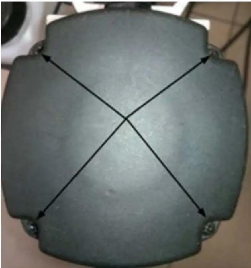
natural_image
Top-down view of a gray cylindrical object with four black arrows pointing diagonally across its center, no text or symbols present.- Lift the housing gently and move the brush protection upwards and unscrew the brush fixing screw:
natural_image
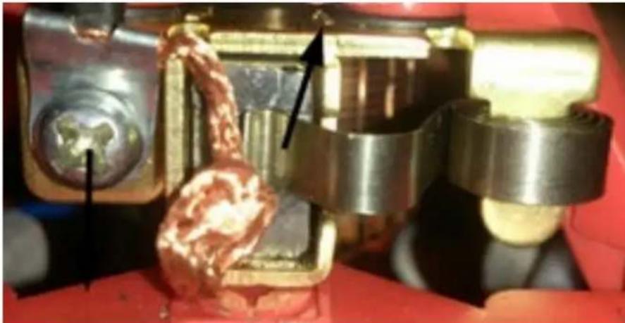
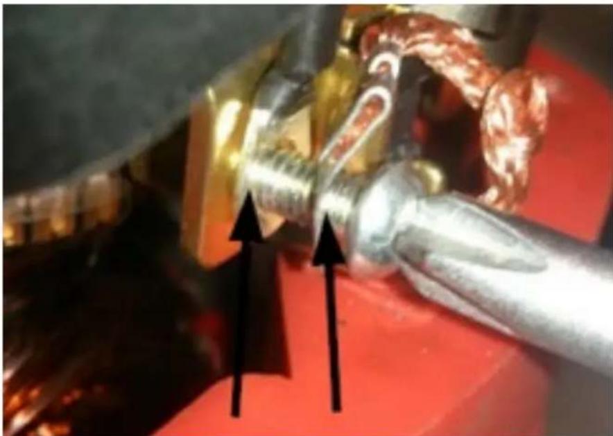
Close-up of mechanical components with metallic and brass parts, no visible text or symbols- Remove the used carbon brush, in its place it is necessary to insert a new carbon brush of the same type. Tighten the brush fixing screw, put on the carbon brush protection and put on and screw the carbon brush housing.
NOTE! When installing and screwing a new brush, remember to put the fixing screw through both eyelets:

natural_image
Close-up of a metallic mechanical component with two black arrows pointing to features, against a red background (no text or symbols visible)XI. Assembly/disassembly of the device's elements
- Assembling of the drill chuck:
Slide the drill chuck into the device, at the end of inserting, gently turn the handle so that it will "click" properly:
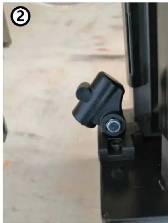
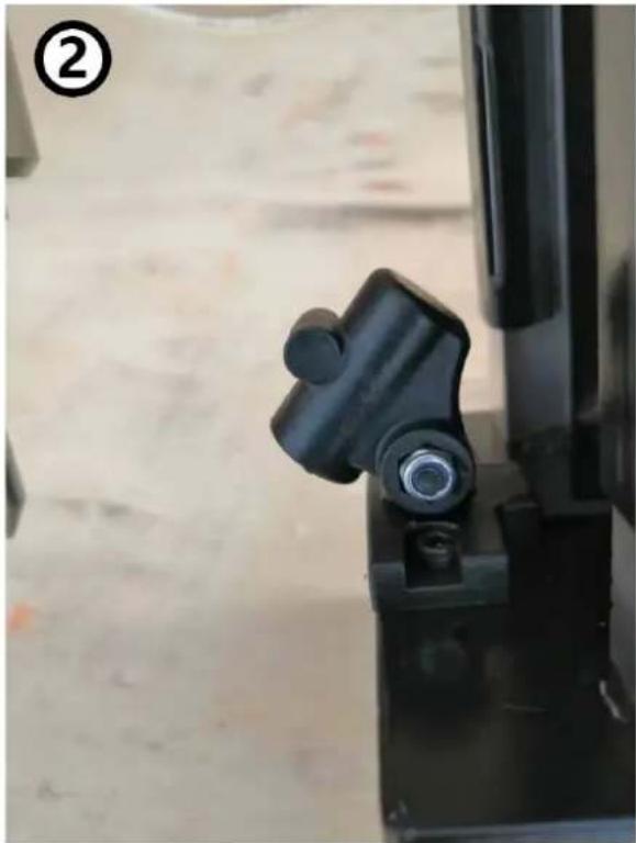
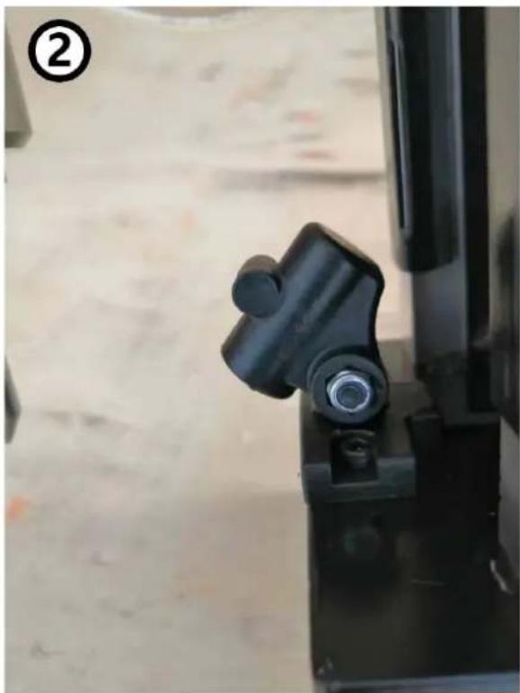
- Installation of the drill height adjustment handles:
The handles must be screwed by turning them clockwise:
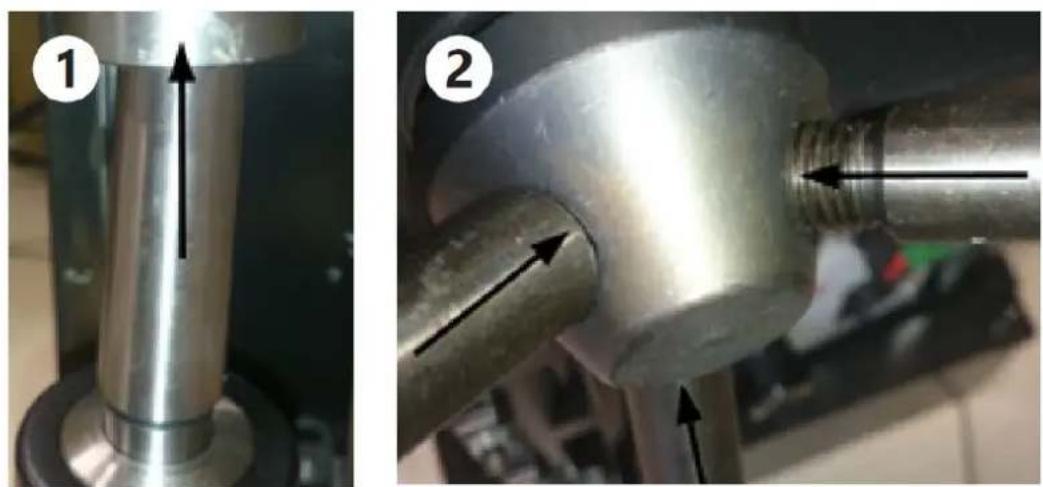
natural_image
Two views of a metallic pipe fitting with arrows indicating direction, labeled 1 and 2 (no text or symbols on the parts themselves)- Loosening the nuts securing the small coolant tank:
Loosen the nuts fastening the small tank:
- Installing the small coolant tank:
Slide the holder of the small tank onto the loose nuts and then tighten them:
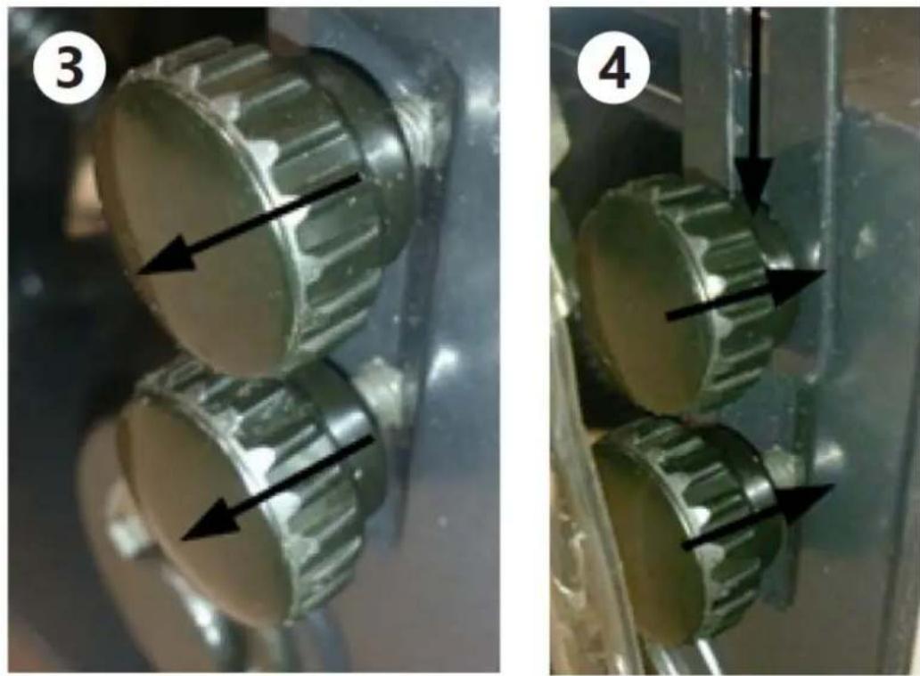
natural_image
Two views of a mechanical component with arrows indicating direction, labeled (3) and (4), showing no text or symbols.XII. Maintenance and inspection
1. Inspecting the tool:
Since the use of a dull tool will cause the motor to malfunction, it should be replaced with a new one without delay when abrasion is noted.
2. Inspecting the mounting screws:
Regularly inspect all mounting screws and ensure that they are properly tightened. Should any of the screws be loose, retighten them immediately. Failure to do so could result in serious hazard.
3. Maintenance of the motor:
The motor unit winding is the very “heart” of the power tool. Exercise due care to ensure the winding does not become damaged and/or wet with oil or water.
4. Inspecting the carbon brushes:
The motor employs carbon brushes which are consumable parts. When they become worn or near the “wear limit”, it could result in motor trouble. When an auto-stop carbon brush is equipped, the motor will stop automatically. At that time, replace both carbon brushes with new ones. In addition, always keep carbon brushes clean and ensure that they slide freely within the brush holders.
5. Cleaning the device:
To keep the device clean, clean it using a soft cloth damped in water with soap. Never use brushes or other cleaning tools that may scratch/damage the device. Remember to prevent water from penetrating inside the device through vents in the housing of the device. Clean the vents with a paintbrush and compressed air.
XIII. Transportation and storage
Shaking, crashing and turning the machine upside down should be prevented when it is transported. Store it in a properly ventilated surrounding with dry air and without any corrosive gas.
XIV. Regular control of the device
Regularly check the machine for signs of damage. Should it be damaged, please stop using it immediately and contact your customer service to solve the problem.
What to do in case of a problem?
Please contact your customer service and prepare following information:
- Invoice number and serial number (the latter is to be found on the technical plate on the machine).
- If relevant, a picture of the damaged, broken or defective part.
- It will be easier for your customer service clerk to determine the source of the problem if you give a detailed and precise description of the matter. The more detailed your information, the better customer service will be able to solve your problem rapidly and efficiently!
CAUTION: Never open the machine without the authorization of your customer service. This can lead to a loss of warranty!

Modele MSW-MD32-ECO/MSW-MD32-PRO/MSW-MD60-ECO/MSW-MD60-PRO:

A - obroty:
natural_image
Close-up of a black mechanical clamp or bracket component with a bolt, mounted on a metal frame (no visible text or symbols)natural_image
Top-down view of a gray cylindrical object with four cross-shaped arrows pointing inward, no text or symbols present.natural_image
Close-up of mechanical components with metallic and brass parts, no visible text or symbolsnatural_image
Close-up of a metallic tool with two black arrows pointing upward, against a red background (no text or symbols)natural_image
Close-up of a metallic cylindrical object with an upward arrow, labeled with number 1 (no text or symbols on the object itself)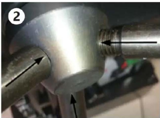
natural_image
Close-up of a metallic mechanical component with threaded end and directional arrows indicating movement (no text or symbols)natural_image
Close-up of two metallic mechanical components with black arrows pointing to features (no text or symbols visible)
natural_image
Close-up of two metallic gears with black arrows indicating direction, no visible text or symbolsModely MSW-MD32-ECO/MSW-MD32-PRO/MSW-MD60-ECO/MSW-MD60-PRO:

A - rotace:
natural_image
Close-up of a black mechanical clamp or bracket component with a circular head and screw, placed on a concrete surface (no visible text or symbols)natural_image
Top-down view of a gray cylindrical object with four black arrows pointing diagonally across its center, placed on a tiled floor (no text or symbols)natural_image
Close-up of mechanical components with metallic and brass parts, no visible text or symbolsnatural_image
Close-up of a metallic mechanical component with two black arrows pointing to features, set against a red background (no text or symbols visible)natural_image
Two views of a metallic pipe fitting with arrows indicating direction, labeled 1 and 2 (no text or symbols on the parts themselves)natural_image
Two views of a mechanical component with arrows indicating direction, labeled (3) and (4), showing no text or symbols.natural_image
Close-up of a black mechanical clamp or bracket component with a bolt, mounted on a metal frame (no visible text or symbols)natural_image
Top-down view of a dark gray mechanical component with four cross-shaped arrows indicating direction (no text or symbols)natural_image
Close-up of mechanical components with metallic and brass parts, no visible text or symbolsnatural_image
Close-up of a metallic mechanical component with two black arrows pointing to features, set against a red background (no text or symbols visible)natural_image
Close-up of two metallic mechanical gears with black arrows indicating direction (no text or symbols)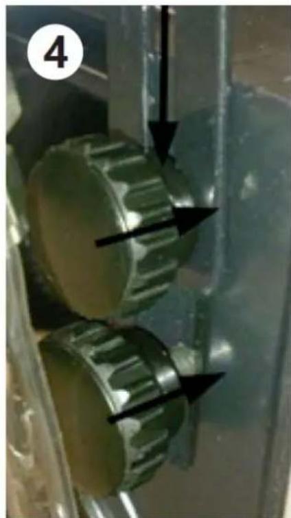
natural_image
Close-up of two metallic gears with black arrows pointing to them, no visible text or symbolsModelli MSW-MD32-ECO/MSW-MD32-PRO/MSW-MD60-ECO/MSW-MD60-PRO:

A - rotazioni:
natural_image
Close-up of a black mechanical clamp or bracket component with a bolt, mounted on a metal frame (no visible text or symbols)natural_image
Top-down view of a gray mechanical component with four black arrows pointing diagonally across its center (no text or symbols)IT
natural_image
Close-up of a metallic cylindrical object with an upward arrow, labeled with number 1 (no text or symbols on the object itself)
natural_image
Close-up of a metallic pipe fitting with threaded end and directional arrows indicating flow or movement (no text or symbols)natural_image
Close-up of two metallic mechanical components with black arrows pointing to features (no text or symbols visible)
natural_image
Close-up of two metallic gears with black arrows indicating direction, no visible text or symbolsModelos MSW-MD32-ECO/MSW-MD32-PRO/MSW-MD60-ECO/MSW-MD60-PRO:

A - rotaciones:
natural_image
Close-up of a black mechanical clamp or bracket component with a bolt, mounted on a metal frame (no visible text or symbols)natural_image
Top-down view of a gray mechanical component with four black arrows pointing diagonally across its center (no text or symbols)natural_image
Close-up of mechanical components with metallic and brass parts, no visible text or symbolsnatural_image
Close-up of a metallic mechanical component with two black arrows pointing to features, against a red background (no text or symbols visible)natural_image
Close-up of a metallic cylindrical object with an upward arrow, labeled with number 1 (no text or symbols on the object itself)
natural_image
Close-up of a metallic pipe fitting with threaded end and directional arrows indicating flow or movement (no text or symbols)natural_image
Close-up of two metallic mechanical components with black arrows pointing to features (no text or symbols visible)
natural_image
Close-up of two metallic gears with black arrows pointing to them, no visible text or symbolsMSW-MD32-ECO/MSW-MD32-PRO/MSW-MD60-ECO/MSW-MD60-PRO modellek:

A - forgások:
- L - bal;
R - jobb;
• 0 – semleges helyzet
natural_image
Two industrial equipment components: one showing a yellow-orange knob labeled 'Electricator Control' and the other a black mechanical clamp (no visible text or symbols)natural_image
Top-down view of a gray cylindrical object with four black arrows pointing diagonally across its center, no text or symbols present.natural_image
Close-up of mechanical components with metallic and brass parts, no visible text or symbolsnatural_image
Close-up of a metallic mechanical component with two black arrows pointing to features, set against a red background (no visible text or symbols)natural_image
Two views of a metallic pipe fitting with directional arrows indicating movement (no text or symbols present)natural_image
Two views of a mechanical component with arrows indicating direction, labeled (3) and (4), showing no text or symbols.Modeller MSW-MD32-ECO/MSW-MD32-PRO/MSW-MD60-ECO/MSW-MD60-PRO:
A - rotationer:
natural_image
Close-up of a black mechanical clamp or bracket component with a circular head and screw, placed on a concrete surface (no visible text or symbols)natural_image
Top-down view of a gray cylindrical object with four cross-shaped arrows pointing inward, no text or symbols present.natural_image
Close-up of mechanical components with metallic and brass parts, no visible text or symbolsnatural_image
Close-up of a metallic mechanical component with two black arrows pointing to features, against a red background (no text or symbols visible)XI. Montering/afmontering af apparatets elementer
natural_image
Two mechanical components with arrows indicating direction of movement, no visible text or symbolsnatural_image
Two views of a mechanical component with arrows indicating direction, labeled 3 and 4 (no text or symbols on the components themselves)Mallit MSW-MD32-ECO/MSW-MD32-PRO/MSW-MD60-ECO/MSW-MD60-PRO:

A - kierrokset:
natural_image
Close-up of a black mechanical clamp or bracket component with a circular head and screw, placed on a concrete surface (no visible text or symbols)natural_image
Top-down view of a gray cylindrical object with four black arrows pointing diagonally across its center (no text or symbols)natural_image
Close-up of mechanical components with metallic parts and a rusted metal surface, no visible text or symbolsnatural_image
Close-up of a metallic pipe joint with two black arrows pointing upward, against a red background (no text or symbols)XI. Laitteen osien kokoaminen/purkaminen
natural_image
Close-up of a metallic cylindrical object with an upward arrow, labeled with number 1 (no text or symbols on the object itself)
natural_image
Close-up of a metallic pipe fitting with threaded end and directional arrows indicating flow or movement (no text or symbols)natural_image
Close-up of two metallic mechanical components with black arrows indicating direction (no text or symbols)
natural_image
Close-up of two metallic gears mounted on a metal frame, with arrows pointing to them (no text or symbols visible)Modellen MSW-MD32-ECO/MSW-MD32-PRO/MSW-MD60-ECO/MSW-MD60-PRO:
A - rotaties:
- L-links;
• R – rechts; - 0 – neutrale positie
natural_image
Close-up of a black mechanical clamp or bracket component with a bolt, mounted on a metal frame (no visible text or symbols)IX. Hoe gebruik je de magneetboormachine?
natural_image
Close-up of mechanical components with metallic and brass parts, no visible text or symbolsnatural_image
Close-up of a metallic mechanical component with two black arrows pointing to features, set against a red background (no visible text or symbols)natural_image
Close-up of a metallic cylindrical object with an upward arrow, labeled (1), no visible text or symbols on the object itself.
natural_image
Close-up of a metallic mechanical component with threaded end and directional arrows indicating movement (no text or symbols)natural_image
Close-up of two metallic mechanical components with black arrows pointing to them, no visible text or symbols
natural_image
Close-up of two metallic gears with black arrows indicating direction, no visible text or symbolsModeller MSW-MD32-ECO/MSW-MD32-PRO/MSW-MD60-ECO/MSW-MD60-PRO:

A - rotasjoner:
IX. Slik bruker du magnetboret
natural_image
Top-down view of a gray cylindrical object with four black arrows pointing diagonally across its center, no text or symbols present.natural_image
Close-up of mechanical components with metallic parts and a rusted metal surface, no visible text or symbolsnatural_image
Close-up of a metallic pipe joint with two black arrows pointing upward, against a red background (no text or symbols)natural_image
Close-up of a metallic cylindrical object with an upward arrow, labeled with number 1 (no text or symbols on the object itself)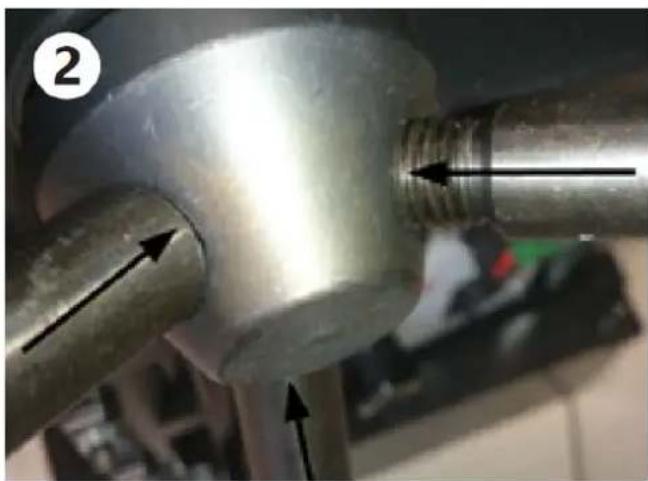
natural_image
Close-up of a metallic pipe joint with threaded end and directional arrows indicating flow or movement (no text or symbols)natural_image
Close-up of two metallic mechanical components with black arrows pointing to features (no text or symbols visible)
natural_image
Close-up of two metallic gears with black arrows pointing to them, no visible text or symbolsModeller MSW-MD32-ECO/MSW-MD32-PRO/MSW-MD60-ECO/MSW-MD60-PRO:

A - rotationer:
natural_image
Close-up of a black mechanical clamp or bracket component with a circular head and screw, placed on a concrete floor (no visible text or symbols)natural_image
Top-down view of a gray cylindrical object with four black arrows pointing diagonally across its center, no text or symbols present.natural_image
Close-up of mechanical components with metallic and brass parts, no visible text or symbolsnatural_image
Close-up of a metallic mechanical component with two black arrows pointing to features, against a red background (no text or symbols visible)natural_image
Close-up of a metallic cylindrical object with an upward arrow, labeled with number 1 (no text or symbols on the object itself)
natural_image
Close-up of a metallic pipe fitting with threaded end and directional arrows indicating flow or movement (no text or symbols)natural_image
Close-up of two metallic mechanical components with black arrows pointing to features (no text or symbols visible)
natural_image
Close-up of two metallic gears with black arrows pointing to them, no visible text or symbolsModelos MSW-MD32-ECO/MSW-MD32-PRO/MSW-MD60-ECO/MSW-MD60-PRO:
A - rotações:

natural_image
Close-up of a black mechanical clamp or bracket component with a bolt, mounted on a metal frame (no visible text or symbols)IX. Como usar a furadeira magnética
natural_image
Top-down view of a gray cylindrical object with four cross-shaped arrows pointing inward, no text or symbols present.natural_image
Close-up of mechanical components with metallic and brass parts, no visible text or symbolsnatural_image
Close-up of a metallic pipe joint with two black arrows pointing to features, against a red background (no text or symbols)natural_image
Two mechanical components with arrows indicating direction of movement, no visible text or symbolsnatural_image
Close-up of two metallic mechanical components with black arrows pointing to features (no text or symbols visible)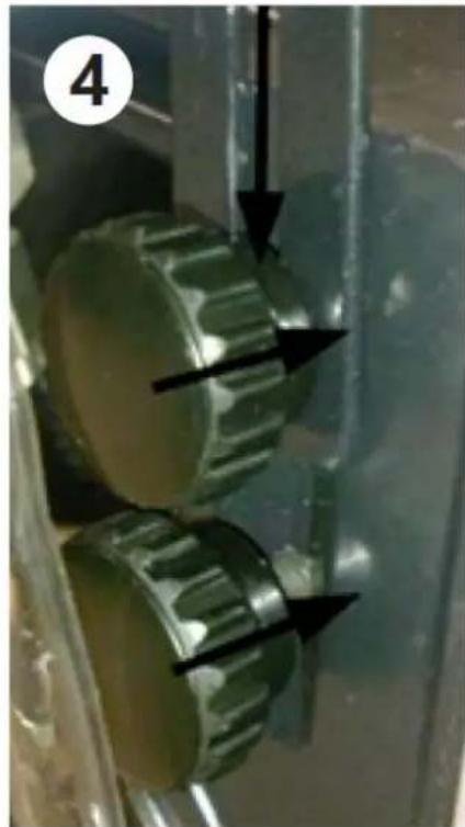
natural_image
Close-up of two metallic mechanical gears with black arrows indicating motion or movement, no visible text or symbolsModely MSW-MD32-ECO/MSW-MD32-PRO/MSW-MD60-ECO/MSW-MD60-PRO:
A - rotácie:
natural_image
Close-up of a black mechanical clamp or bracket component with a circular head and screw, placed on a concrete surface (no visible text or symbols)natural_image
Close-up of mechanical components with metallic and brass parts, no visible text or symbolsnatural_image
Close-up of a metallic mechanical component with two black arrows pointing to features, against a red background (no text or symbols visible)natural_image
Close-up of a metallic cylindrical object with an upward arrow, labeled with number 1 (no text or symbols on the object itself)
natural_image
Close-up of a metallic pipe fitting with threaded end and directional arrows indicating flow or movement (no text or symbols)natural_image
Close-up of two metallic mechanical components with black arrows indicating direction (no text or symbols)
natural_image
Close-up of two metallic gears with black arrows indicating direction, no visible text or symbolsМодели MSW-MD32-ECO/MSW-MD32-PRO/MSW-MD60-ECO/MSW-MD60-PRO:

A - ротации:
natural_image
Top-down view of a gray cylindrical object with four black arrows pointing diagonally across its center (no text or symbols)natural_image
Close-up of mechanical components with metallic and brass parts, no visible text or symbolsnatural_image
Close-up of a metallic mechanical component with two black arrows pointing to features, against a red background (no text or symbols visible)Μοντέλα MSW-MD32-ECO/MSW-MD32-PRO/MSW-MD60-ECO/MSW-MD60-PRO:

A - περιστροφές:
natural_image
Two-panel photo showing a black industrial machine component with a yellow indicator light and a black mechanical clamp, both without any visible text or symbols.natural_image
Top-down view of a gray mechanical component with four cross-shaped arrows indicating direction (no text or symbols)natural_image
Close-up of mechanical components with metallic parts and a rusted metal surface, no visible text or symbolsnatural_image
Close-up of a metallic pipe joint with two black arrows pointing to features, against a red background (no text or symbols)1 - ulaz zraka/poklopac karbonskih četkica motora
2 - motor
3 - pričvrsni vijci
4 - vreteno
5 - konzola/transportna ručka
6 - ručke za podešavanje visine bušilice
7 - poluga za podizanje/spuštanje uređaja
8 - željeznicom
9 - upravljačka ploča
10 - strujni kabel
11 - magnet
Modeli MSW-MD32-ECO/MSW-MD32-PRO/MSW-MD60-ECO/MSW-MD60-PRO:

A - rotacije:
natural_image
Top-down view of a gray cylindrical object with four black arrows pointing diagonally across its center, no text or symbols present.- Lagano podignite kućište i pomaknite zaštitu četkice prema gore te odvrnite vijak za pričvršćivanje četkice:

natural_image
Close-up of mechanical components with metallic and brass parts, no visible text or symbols- Uklonite korištenu ugljenu četkicu, umjesto nje potrebno je umetnuti novu ugljenu četkicu iste vrste. Zategnite vijak za pričvršćivanje četkica, stavite zaštitu od karbonskih četkica te postavite i zavrnite kućište karbonskih četkica.
BILJEŠKA! Prilikom postavljanja i pričvršćivanja nove četke, ne zaboravite provući pričvrsni vijak kroz obje ušice:
natural_image
Close-up of a metallic mechanical component with two black arrows pointing to features, against a red background (no text or symbols visible)XI. Montaža/demontaža elemenata uređaja
- Sastavljanje stezne glave bušilice:
Gurnite steznu glavu bušilice u uređaj, na kraju umetanja lagano okrenite ručicu da pravilno „klikne“:
- Ugradnja ručki za podešavanje visine bušilice:
natural_image
Close-up of a metallic cylindrical object with an upward arrow, labeled with number 1 (no text or symbols on the object itself)
natural_image
Close-up of a metallic pipe fitting with threaded end and directional arrows indicating flow or movement (no text or symbols)natural_image
Close-up of two metallic mechanical components with black arrows pointing to them, no visible text or symbols
natural_image
Close-up of two metallic gears with black arrows pointing to them, no visible text or symbolsXII. Održavanje i pregled
1. Pregled alata:
Modeliai MSW-MD32-ECO/MSW-MD32-PRO/MSW-MD60-ECO/MSW-MD60-PRO:

A - sukimai:
natural_image
Close-up of a black mechanical clamp or bracket component with a circular head and screw, placed on a concrete floor (no visible text or symbols)IX. Kaip naudotis magnetiniu grąžtu
natural_image
Top-down view of a gray cylindrical object with four black arrows pointing diagonally across its center, no text or symbols present.LT
natural_image
Two views of a metallic mechanical component with arrows indicating direction, labeled 1 and 2 (no text or symbols on the parts themselves)natural_image
Two views of a mechanical component with arrows indicating direction, labeled 3 and 4 (no text or symbols on the components themselves)Modele MSW-MD32-ECO/MSW-MD32-PRO/MSW-MD60-ECO/MSW-MD60-PRO:

A - rotatii:
natural_image
Close-up of a black mechanical clamp or bracket component with a circular head and screw, placed on a concrete floor (no visible text or symbols)natural_image
Top-down view of a dark gray mechanical component with four directional arrows indicating cross-section (no text or symbols)natural_image
Close-up of mechanical components with metallic parts and a rusted metal surface, no visible text or symbolsnatural_image
Close-up of a metallic mechanical component with two black arrows pointing to features, set against a red background (no text or symbols visible)natural_image
Close-up of a metallic cylindrical object with an upward arrow, labeled with number 1 (no text or symbols on the object itself)
natural_image
Close-up of a metallic pipe joint with threaded end and directional arrows indicating flow or movement (no text or symbols)natural_image
Close-up of two metallic mechanical components with black arrows pointing to features (no text or symbols visible)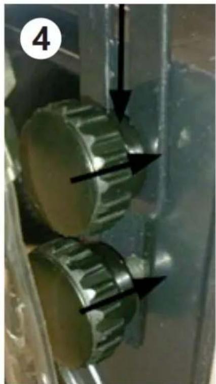
natural_image
Close-up of two metallic gears with black arrows indicating direction, no visible text or symbolsModeli MSW-MD32-ECO/MSW-MD32-PRO/MSW-MD60-ECO/MSW-MD60-PRO:

A - vrtenja:
natural_image
Close-up of a black mechanical clamp or bracket component with a circular head and screw, placed on a concrete floor (no visible text or symbols)natural_image
Top-down view of a gray cylindrical object with four black arrows pointing diagonally across its center, no text or symbols present.natural_image
Close-up of mechanical components with metallic and brass parts, no visible text or symbolsnatural_image
Close-up of a metallic mechanical component with two black arrows pointing to features, set against a red background (no text or symbols visible)XI. Montaža/demontaža elementov naprave
natural_image
Close-up of a metallic cylindrical object with an upward arrow, labeled with number 1 (no text or symbols on the object itself)
natural_image
Close-up of a metallic pipe joint with threaded end and directional arrows indicating flow or movement (no text or symbols)natural_image
Close-up of two metallic mechanical components with black arrows pointing to features (no text or symbols visible)
natural_image
Close-up of two metallic gears with black arrows indicating direction, no visible text or symbolsFor the disposal of the device please consider and act according to the national and local rules and regulations.
CONTACT
expondo Polska sp. z o.o. sp. k.