
Compact 15t - Log splitter SCHEPPACH - Free user manual and instructions
Find the device manual for free Compact 15t SCHEPPACH in PDF.

| Product type | Vertical hydraulic log splitter |
| Brand | Scheppach |
| Model | Compact 15t |
| Max. splitting force | 15 tons |
| Hydraulic pressure | 26.7 MPa |
| Dimensions (L x W x H) | 1160 x 960 x 1100 mm (1650 mm with swivel table) |
| Weight | 191 kg |
| Power supply | 400 V / 50 Hz three-phase |
| Power input | 3.5 kW |
| Power output | 2.5 kW |
| Current consumption | 7.1 A |
| Motor speed | 2800 rpm |
| Oil tank capacity | 7 liters |
| Log length admissible | 75 - 107 cm |
| Log diameter admissible | 12 - 45 cm |
| Swivel table height | 320 mm |
| Working height | 920 mm |
| Sound pressure level (LpA) | 77.8 dB (uncertainty 3 dB) |
| Motor protection | Yes (protection switch) |
| Phase inverter | Yes |
| Operating mode | S6 40% (intermittent operation) |
| Maintenance | Lubricate column every 5h, oil change after 50h then every 500h |
| Safety | Two-hand control, emergency stop, restart protection, retaining claws |
| Wear parts | Splitting wedge, guides, hydraulic oil |
Frequently Asked Questions - Compact 15t SCHEPPACH
User questions about Compact 15t SCHEPPACH
0 question about this device. Answer the ones you know or ask your own.
Ask a new question about this device
Download the instructions for your Log splitter in PDF format for free! Find your manual Compact 15t - SCHEPPACH and take your electronic device back in hand. On this page are published all the documents necessary for the use of your device. Compact 15t by SCHEPPACH.
USER MANUAL Compact 15t SCHEPPACH
Compact 12t Compact 15t

natural_image
Industrial robotic lift with articulated arms and a flat base (no visible text or symbols)
| DE | HolzspalterOriginalbetriebsanleitung | 12 |
| GB | Log splitterTranslation of original instruction manual | 33 |
| FR | Fendeur de bûchesTraduction des instructions d'origine | 51 |
| IT | SpaccalegnaLa traduzione dal manuale di istruzioni originale | 71 |
| NL | HoutsplijterVertaling van de originele gebruikshandleiding | 91 |
| ES | Cortador de maderaTraducción del manual de instrucciones original | 110 |
| PT | FendedeiraTradução do manual de operação original | 130 |
| CZ | Štípač dřevaPřeklad originálního návodu k obsluze | 149 |
| SK | Štiepačka drevaPreklad originálneho návodu na obsluhu | 167 |
| HU | FahasítóEredeti használati utasítás fordítása | 186 |
| PL | Łuparka klinowa do drewnaTłumaczenie oryginalnej instrukcji obsługi | 205 |
| HR | Cjepač drvaPrijevod originalnog priručnika za uporabu | 225 |
| SI | Cepilnik drvPrevod originalnih navodil za uporabo | 243 |
| EE | PuulõhkujaOriginaalkaitusjuhendi tõlge | 261 |
| LT | Medienos skaldytuvasOriginalios naudojimo instrukcijos vertimas | 279 |
| LV | Malkas skaldītājsOriginālās lietošanas instrukcijas tulkojums | 297 |
| SE | VedklyvÖversättning av original-bruksanvisning | 316 |
| FI | HalkaisukoneKäännös alkuperäisestä käyttöohjeesta | 334 |
| DK | TræspalterOversættelse fra den oprindelige betjeningsvejledning | 352 |
| NO | VedkapperOversettelse av den originale brukerveiledningen | 370 |
| BG | Maшина за цепене на дърваПревод на оригиналното ръководство за експлоатация | 387 |
| GR | Σχίστης ξύλουΜετάφραση του πρωτοτύπου των οδηγιών χρήσης | 407 |
| RO | Maşină de despicat lemneTraducere din manualul de exploatare original | 428 |
| RS | Mašina za cepanje drvaPrevod originalnog uputstva za upotrebu | 447 |
| TR | Odun yariciOrijinal kullanım talimatı çevirisi | 465 |
1
2
3
4
22
26
□—25a
25b
26a 26b
25c

18
19
Günzburger Straße 69
D-89335 Ichenhausen
Verehrter Kunde,
Homepage: https://www.scheppach.com/de/service
Explanation of the symbols on the device
Symbols are used in this manual to draw your attention to potential hazards. The safety symbols and the accompanying explanations must be fully understood. The warnings themselves will not rectify a hazard and cannot replace proper accident prevention measures.
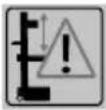
 | Warning - read the instruction manual to reduce the risk of injury. |  | If a crane is used, place the lifting belt around the housing. Never lift the log splitter by the transport handle. |
 | Use safety shoes. |  | Dispose of the used oil properly (waste oil collection point on site). Dumping used oil in the soil or mixing it with waste is prohibited. |
 | Wear safety goggles. Sparks created during work or fragments, chippings and dust ejected by the device can case sight loss. |  | Removing or modifying protective or safety equipment is prohibited. |
 | Use work gloves. |  | Do not remove jammed trunks with your hands. |
 | No entry for unauthorised persons. |  | Attention! Before starting repair, maintenance and cleaning work, switch off the engine and unplug the mains plug. |
 | No smoking in the working area. |  | Cutting and crushing hazard; never touch hazardous areas when the splitting blade is moving. |
  | Keep the work area orderly! Disorder can lead to accidents! |  | High voltage, risk of death! |
 | The machine may only be operated by one person! |  | Direction of rotation of the motor. |
 | Do not transport the device lying on its side! |   | Only the operator may stand in the working area of the machine. Keep uninvolved persons as well as pets and livestock away from the danger zone (minimum distance 5 m). |
 | Caution! Moving tools! | 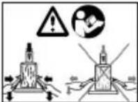 | Familiarise yourself with the two-hand lever operation before commissioning the machine! Read the usage instructions carefully. |
  | Loosen the ventilation screw about 2 turns before starting work. Close before transport. | ⚠ Attention! | We have marked points in these operating instructions that impact your safety with this symbol. |
 | The product complies with the applicable European directives. |  | The product complies with the applicable Serbian directives. |
Table of contents: Page:
- Introduction....36
- Device description (Fig. 1 - 19)....36
- Scope of delivery (Fig. 3, 4).... 37
- Proper use 37
- General safety instructions.... 38
- Additional safety instructions....40
- Technical data....40
- Unpacking....41
- Layout 41
- Before commissioning 43
- Operation 45
- Maintenance and repairs 46
- Storage 48
- Transport....48
- Electrical connection 48
- Disposal and recycling....49
- Troubleshooting 50
- Declaration of conformity 485
1. Introduction
Manufacturer:
Scheppach GmbH
Günzburger Straße 69
D-89335 Ichenhausen
Dear Customer,
We hope your new device brings you much enjoyment and success.
Note:
In accordance with the applicable product liability laws, the manufacturer of this device assumes no liability for damage to the device or caused by the device arising from:
- Improper handling
• Non-compliance with the operating manual,
• Repairs carried out by third parties, unauthorised specialists.
• Installing and replacing non-original spare parts
• Application other than specified - Failure of the electrical system in the event of the electrical regulations and VDE provisions 0100, DIN 57113 / VDE0113 not being observed
Note:
Read through the complete text in the operating manual before installing and commissioning the device.
This operating manual should help you to familiarise yourself with your device and to use it for its intended purpose.
The operating manual includes important instructions for safe, proper and economic operation of the device, for avoiding danger, for minimising repair costs and downtimes, and for increasing the reliability and extending the service life of the device.
In addition to the safety instructions in this operating manual, you must also observe the regulations applicable to the operation of the device in your country.
Keep the operating manual at the device, in a plastic sleeve, protected from dirt and moisture. They must be read and carefully observed by all operating personnel before starting the work.
The device may only be used by personnel who have been trained to use it and who have been instructed with respect to the associated hazards. The required minimum age must be observed.
In addition to the safety instructions in this operating manual and the separate regulations of your country, the generally recognised technical rules relating to the operation of such machines must also be observed.
We accept no liability for accidents or damage that occur due to a failure to observe this manual and the safety instructions.
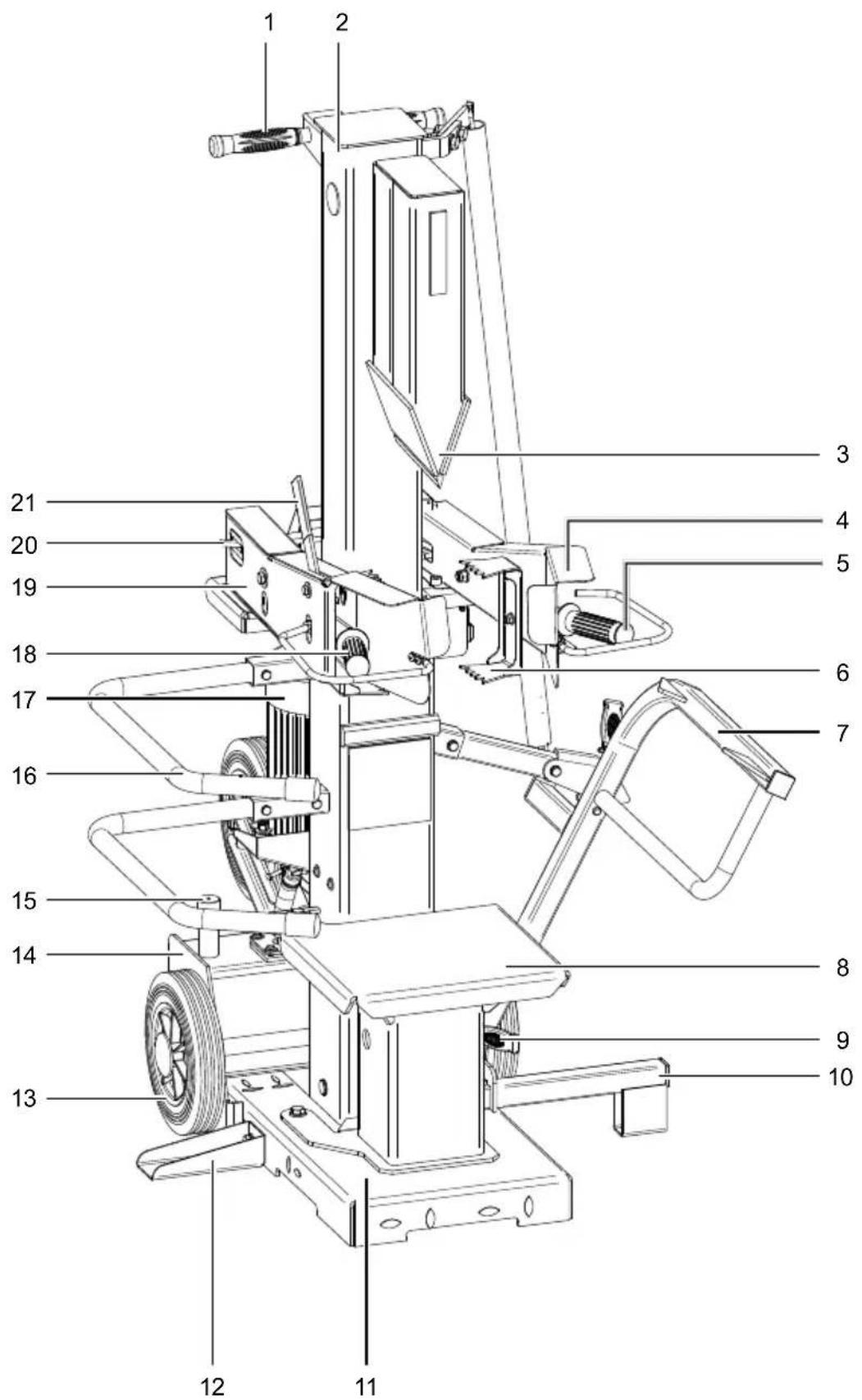
2. Device description (Fig. 1 - 19)
- Transport handle
- Splitting column
- Riving knife
- Control arm right
- Operating lever right
- Retaining claw
6a. Hole - Trunk lifter
7a. Trunk lift holder - Swivel table
- Locking hooks
- Trunk lifting support
10a. Hexagon socket screw M6x10mm - Base plate
- Support
- Transport wheels
- Hydraulic oil tank
- Ventilation screw
- Hoop guard
16a. Holder - Engine
- Operating lever left
- Control arm left
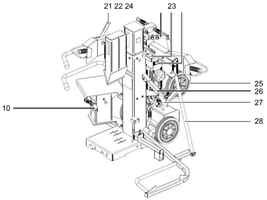
- Rocker switch
- Stop lever
- Chain hook
- Support points
- On/off switch
- Support wheel
- Trunk lift lock
- Lever
- Chain
- Stop screw
- Wheel holder right
- Wheel holder left
- Oil dipstick
- Oil drain screw
- Electrical power connection
- Cap nut (stroke setting bar)
- Locking screw (stroke setting bar)
- Magnetic stop
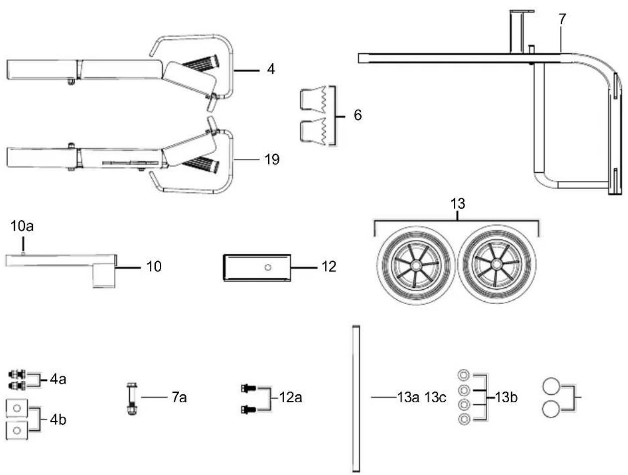
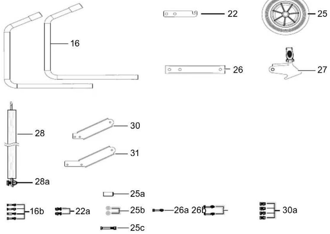
3. Scope of delivery (Fig. 3, 4)
- 1x Log splitter
• 1x Control arm right (4)
• 2x Retaining claws (6) - 1x Trunk lifter (7)
• 1x Trunk lifting support (10)
• 1x Hexagon socket screw M6x10mm (10a) - 1x Support (12)
• 2x Transport wheels (13)
• 2x Protective bars (16)
• 1x Control arm Left (19) - 1x Chain hook (22)
• 1x Support wheel (25)
• 1x Trunk lift lock (26)
• 1x Lever (27) - 1x Chain (28)
• 2x Hexagonal bolt M10x25mm (4a)
• 2x Stiffening plate (4b)
• 1x Hexagonal bolt M12x70mm (7a)
• 2x Hexagonal bolt M10x25mm (12a)
• 1x Wheel axle (13a)
• 4x washer ø 25mm (13b) - 2x Wheel caps (13c)
• 4x M8x50mm hexagonal bolt (16b) - 2x M12x40mm hexagonal bolt (22a)
- 1x Socket (25a)
• 2x Washer M12 (25b)
• 1x M12x85mm hexagonal bolt (25c)
• 1x M8x55mm hexagonal bolt (26a)
• 2x M8x55mm hexagonal bolt (26b) - 1x M12x40mm hexagonal bolt (28a)
• 4x M10x25mm hexagonal bolt (30a)
• 1x operating manual
4. Proper use
The log splitter is designed exclusively for chopping firewood in the direction of the grain.
The machine may only be used in the intended manner. Any use beyond this is improper. The user/operator, not the manufacturer, is responsible for damages or injuries of any type resulting from this.
An element of the intended use is also the observance of the safety instructions, as well as the assembly instructions and operating information in the operating manual.
Persons who operate and maintain the machine must be familiar with it and must be informed about potential dangers.
In addition, the applicable accident prevention regulations must be strictly observed.
Other general occupational health and safety-related rules and regulations must be observed.
The liability of the manufacturer and resulting damages are excluded in the event of modifications of the machine.
- The hydraulic log splitter is only suitable for upright operation. Timbers may only be split vertically in the direction of the grain. The dimensions of the timbers to be split are:
- Wood length: 75 cm - 107 cm
- Wood diameter: 8 cm - 38 cm
- Never split wood horizontally or against the grain!
- The manufacturer's safety, operating and maintenance specifications as well as the dimensions given in the technical data must be observed.
- Relevant accident prevention regulations and other generally recognized safety and technical rules must also be observed.
- The machine may only be used, maintained or repaired by trained persons who are familiar with it and have been informed of the dangers. Any liability of the manufacturer for damages resulting from arbitrary changes to the machine is excluded.
- The machine may only be operated with original accessories and original tools from the manufacturer.
- Any use beyond this is improper use. The manufacturer is not responsible for the resultant damages, the user bears this risk alone.
- Keep the work area clean and free of obstructions.
- Only operate the product on a flat, firm surface.
- Before each commissioning, check that the log splitter is functioning properly.
- Only operate the product in areas that are a maximum of 1000 m above sea level.
- Please note that our equipment was not designed with the intention of use for commercial or industrial purposes. We assume no guarantee if the device is used in commercial or industrial applications, or for equivalent work.
5. General safety instructions
We have marked points in these operating instructions that impact your safety with this symbol: △
⚠ WARNING: When using power tools, the basic safety precautions below must be followed in order to reduce the risk of fire, electric shock, and personal injury. Please read all instructions before working with this tool.
- Observe all safety information and danger notices on the machine.
- Ensure that all of the safety information and danger notices on the machine are complete and in legible condition.
- The safety equipment on the machine must not be disassembled or made unusable.
- Check mains connection cables. Do not use faulty connection cables.
- Check for correct function of the two-hand control before commissioning.
- The operating personnel must be at least 18 years of age.
• Children may not work with this product.
- Wear work and safety gloves, safety glasses, close-, fitting work clothes (PPE) while working.
- Caution when working: Danger of injury for fingers and hands due to the splitting tool.
- Modification, adjustment and cleaning work, as well as maintenance and rectification of faults may only be carried out when the engine is switched off. Pull out the mains plug!
• Installation, repairs and maintenance work on the electrical equipment may only be carried out by electricians.
- All protective and safety equipment must be reassembled immediately after repair, maintenance is completed.
- Switch off the engine when leaving the work station. Pull out the mains plug!
Removing or working without guards is prohibited.
- When splitting, the properties of the wood (e.g. growths, trunk slices of irregular shape, etc.) can result in hazards such as ejecting parts, jamming the log splitter, and crushing.
- Apart from the operator, it is forbidden to stand within the working radius of the machine. No other person or animal may be present within a 5 metre radius of the machine.
- The discharging of waste oil into the environment is prohibited. The oil must be disposed of in accordance with the legal requirements of the country in which the operation takes place.
⚠️ Cutting or crushing hazard to hands:
- Never touch dangerous areas while the wedge is moving.
⚠ Warning!
Never remove a trunk that is caught in the wedge by hand.
⚠ Warning!
Always pull out the mains plug before carrying out maintenance work.
Store these instructions safely!
General power tool safety warnings
⚠ WARNING! Read all safety warnings, instructions, illustrations and specifications provided with this power tool. Failure to follow all instructions listed below may result in electric shock, fire and/or serious injury.
Save all warnings and instructions for future reference.
The term "power tool" in the warnings refers to your mains-operated (corded) power tool or battery-operated (cordless) power tool.
Work area safety
- Keep your work area clean and well-lit. Cluttered or dark areas invite accidents.
- Do not operate power tools in explosive atmospheres, such as in the presence of flammable liquids, gases or dust.
Power tools create sparks which may ignite the dust or fumes.
- Keep children and bystanders away while operating a power tool.
Distractions can cause you to lose control.
Electrical safety
Attention!
The following basic safety measures must be observed when using electric tools for protection against electric shock, and the risk of injury and fire. Read all these notices before using the power tool and store the safety instructions well for later reference.
- Avoid physical contact with earthed or grounded surfaces, such as pipes, radiators, ranges and refrigerators. There is an increased risk of electric shock if your body is earthed or grounded.
- Keep the device away from rain and moisture. Water entering a power tool will increase the risk of electric shock.
- Do not use the cable for another purpose, for example, carrying or hanging the device or pulling the plug out of the socket. Keep the cable away from heat, oil, sharp edges or moving device parts. Damaged or coiled cables increase the risk of an electric shock.
- If you work with an electric tool outdoors, only use extension cables that are also permitted for outdoor use. Using an extension cable permitted for outdoor use reduces the risk of an electric shock.
Personal safety
- Stay alert, watch what you are doing and use common sense when operating a power tool.
Do not use a power tool while you are tired or under the influence of drugs, alcohol or medication. A moment of carelessness when using electrical tools can result in serious injuries.
- Wearing personal protective equipment such as a dust mask, non-skid safety shoes to suit the respective use of the power tool will reduce the risk of personal injuries.
- Prevent unintentional starting. Make sure the switch is in the off-position before connecting to the power supply, picking up or carrying the electric tool. Carrying power tools with your finger on the switch or energising power tools that have the switch on invites accidents.
- Remove any adjusting key or screwdriver before turning the power tool on.
A wrench or a key left attached to a rotating part of the power tool may result in personal injury.
- Do not overreach.
Keep proper footing and balance at all times. This enables better control of the power tool in unexpected situations.
- Dress properly. Do not wear loose clothing or jewellery. Keep hair, clothing and gloves away from moving parts. Loose clothes, jewellery or long hair can be caught in moving parts.
- Do not let familiarity gained from frequent use of tools allow you to become complacent and ignore tool safety principles. A careless action can cause severe injury within a fraction of a second.
Power tool use and care
- Do not force the power tool.
Use the correct power tool for your application. The correct power tool will do the job better and safer at the rate for which it was designed.
- Do not use the power tool if the switch does not turn it on and off. Any power tool that cannot be controlled with the switch is dangerous and must be repaired.
- Disconnect the plug from the power socket before making any adjustments to the device, changing tool inserts or transporting the power tool.
Such preventive safety measures reduce the risk of starting the power tool accidentally.
- Store idle power tools out of the reach of children and
do not allow persons unfamiliar with the power tool or these instructions to operate the power tool. Power tools are dangerous in the hands of untrained users.
- Maintain power tools and accessories.
Check whether moving parts function properly and do not get stuck and whether parts are broken or are damaged and thus adversely affect the electric tool function. If damaged, have the power tool repaired before use. Many accidents are caused by poorly maintained power tools.
- Keep cutting tools sharp and clean. Properly maintained cutting tools with sharp cutting edges are less likely to bind and are easier to control.
- Use the power tool, accessories and tool bits etc. in accordance with these instructions, taking into account the working conditions and the work to be performed. Use of the power tool for operations different from those intended could result in a hazardous situation.
- Keep handles and grasping surfaces dry, clean and free from oil and grease. Slippery handles and grasping surfaces do not allow for safe handling and control of the tool in unexpected situations.
Service
- Only have your electric tool repaired by qualified specialists and only with original spare parts. This will ensure that the safety of the power tool is maintained.
6. Additional safety instructions
- The log splitter may only be operated by a single person.
- Never split trunks that contain nails, wire, or other objects.
- Wood that has already been split and wood chippings create a hazardous work area. There is a danger of tripping, slipping or falling. Always keep the work area orderly.
- Never place your hands on moving parts of the machine when it is switched on.
- Only split wood with a maximum length of 107 cm.
⚠ Warning! This power tool generates an electromagnetic field during operation. This field can impair active or passive medical implants under certain circumstances. In order to prevent the risk of serious or deadly injuries, we recommend that persons with medical implants consult with their physician and the manufacturer of the medical implant prior to operating the power tool.
Residual risks
The machine has been built according to the state-of-the-art and the recognised technical safety requirements. However, individual residual risks can arise during operation.
- Danger of injury for fingers and hands from the splitting tool in the event of improper guiding or support of the wood.
- Injuries due to the workpiece being ejected at high speed due to improper holding or guiding.
• Health hazard due to electrical power, with the use of improper electrical connection cables. - Switch off the device and pull out the mains plug before carrying out any setting or maintenance work.
• Furthermore, despite all precautions having been met, some non-obvious residual risks may still remain. -
Residual risks can be minimised if the "Safety Instructions" and the "Intended Use" together with the operating manual as a whole are observed.
-
Avoid accidental starting of the machine: the operating button may not be pressed when inserting the plug in an outlet. Use the tool that is recommended in this operating manual.
- This is how to ensure that your machine provides optimum performance.
-
Keep your hands away from the working area when the machine is in operation.
-
Technical data
| Compact 12t | Compact 15t | |
| Dimensions DxWxH mm 1160x960x1100 / 1650 | ||
| Swivel table height mm 320 | ||
| Working height mm 920 | ||
| Min./max. wood length cm | 75 / 107 | |
| Max. power t* 12 15 | ||
| Hydraulic pressure MPa 24 26,7 | ||
| Cylinder stroke cm 55,0 | ||
| Feed speed cm/s 3,8 | ||
| Return speed cm/s 12,8 | ||
| Oil quantity l | 7 | |
| Min./max. wood diameter cm | 12 – 45 | |
| Weight kg | 191 | |
| Drive | ||
| Motor V/Hz | 400/50 | |
| Rated input P1 kW | 3,5 | |
| Power output P2 kW | 2,5 | |
| Input current A | 7,1 | |
| Short-circuit resistance kA | 1 | |
| Operating mode | S6/40% / IP54 | |
| Speed 1/min | 2800 | |
| Motor protection | Yes | |
| Phase inverter | Yes | |
Subject to technical changes!
* The maximum achievable splitting force is dependent on the resistance of the log and can differ due to variable contributing factors on the hydraulic system.
** Operating mode S6 40%, uninterrupted periodic operation with intermittent load. The mode comprises of a start-up period, a time with constant load and an idle time. The operating time is 10 mins, the relative duty cycle is 40% of the operating time.
Noise
The noise levels have been determined in accordance with EN 62841.
| Sound pressure level L_pA | 77.8 dB |
| Uncertainty K_pA | 3 dB |
| Sound power level L_WA | 93.6 dB |
| Uncertainty K_WA | 3 dB |
Excessive noise can result in a loss of hearing.
The specified noise emission values have been measured in accordance with a standardised test procedure and can be used to compare one power tool with another.
The specified device emissions values can also be used for an initial estimation of the load.
Warning:
- The noise emission values can vary from the specified values during the actual use of the power tool, depending on the type and the manner in which the power tool is used, and in particular the type of workpiece being processed.
- Try to keep the stress as low as possible. For example: Limit working time. In doing so, all parts of the operating cycle must be taken into account (such as times in which the power tool is switched off or times in which it is switched on, but is not running under a load).
8. Unpacking
- Open the packaging and carefully remove the device.
- Remove the packaging material, as well as the packaging and transport safety devices (if present).
- Check whether the scope of delivery is complete.
-
Check the device and accessory parts for transport damage. In the event of complaints the carrier must be informed immediately. Later claims will not be recognised.
-
If possible, keep the packaging until the expiry of the warranty period.
- Familiarise yourself with the product by means of the operating manual before using for the first time.
- With accessories as well as wearing parts and replacement parts use only original parts. Spare parts can be obtained from your specialist dealer.
- When ordering please provide our article number as well as type and year of manufacture for the product.
⚠ WARNING!
Danger of choking and suffocating!
The packaging material, packaging and transport safety devices are not children's toys. Plastic bags, foils and small parts can be swallowed and lead to choking.
- Keep packaging material, packaging and transport safety devices away from children.
9. Layout
Your log splitter is not completely assembled for packaging reasons.
Note
Due to the heavy weight of the product, we recommend installation by at least two people.
You require the following for assembly:
- 2x open-ended spanner / socket spanner, size 13mm
- 2x open-ended spanner / socket spanner, size 16mm
- 2x open-ended spanner / socket spanner, size 19mm
- 1x wooden base
• 1x soft-face hammer
• 1x socket spanner attachment 32mm
• 1x 8mm Allen key - Grease or spray oil
Not included in the scope of delivery.
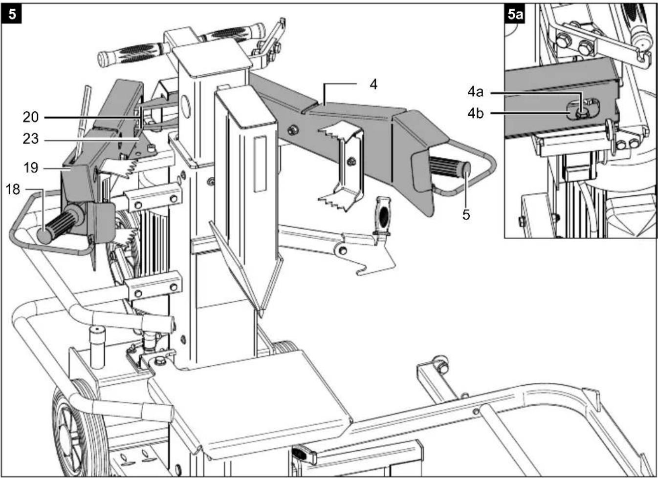
9.1 Fit the operating arm on the right (4) and the operating arm on the left (19) (Fig. 5, 5a)
Note: The operating arm on the right (4) is marked R (right) and the operating arm on the left (19) is marked L (left).
-
Apply a light film of grease or spray oil to the lower support points (23) of the operating arm on the right (4) and the operating arm on the left (19) respectively.
-
Attach the operating arm right(4). At the same time, guide the rocker switch (20) through the slot in the operating lever right (5).
- Fix the operating arm on the right (4) by inserting a hexagon head screw M10x25mm (4a) with washer and stiffening plate (4b) from above and secure it from below with a lock nut. Tighten the hexagon head screw M10x25mm (4a) only so tight that the operating arm on the right (4) can still be moved. Use two 16mm open-ended spanners / socket spanners.
- Attach the operating arm left (19). At the same time, guide both rocker switches (20) through the slot in the operating lever left (18).
- Fix the operating arm on the left (19) by inserting a hexagon head screw M10x25mm (4a) with washer and stiffening plate (4b) from above and secure it from below with a lock nut. Tighten the hexagon head screw M10x25mm (4a) only so tight that the operating arm on the left (19) can still be moved. Use two 16mm open-ended spanners / socket spanners.
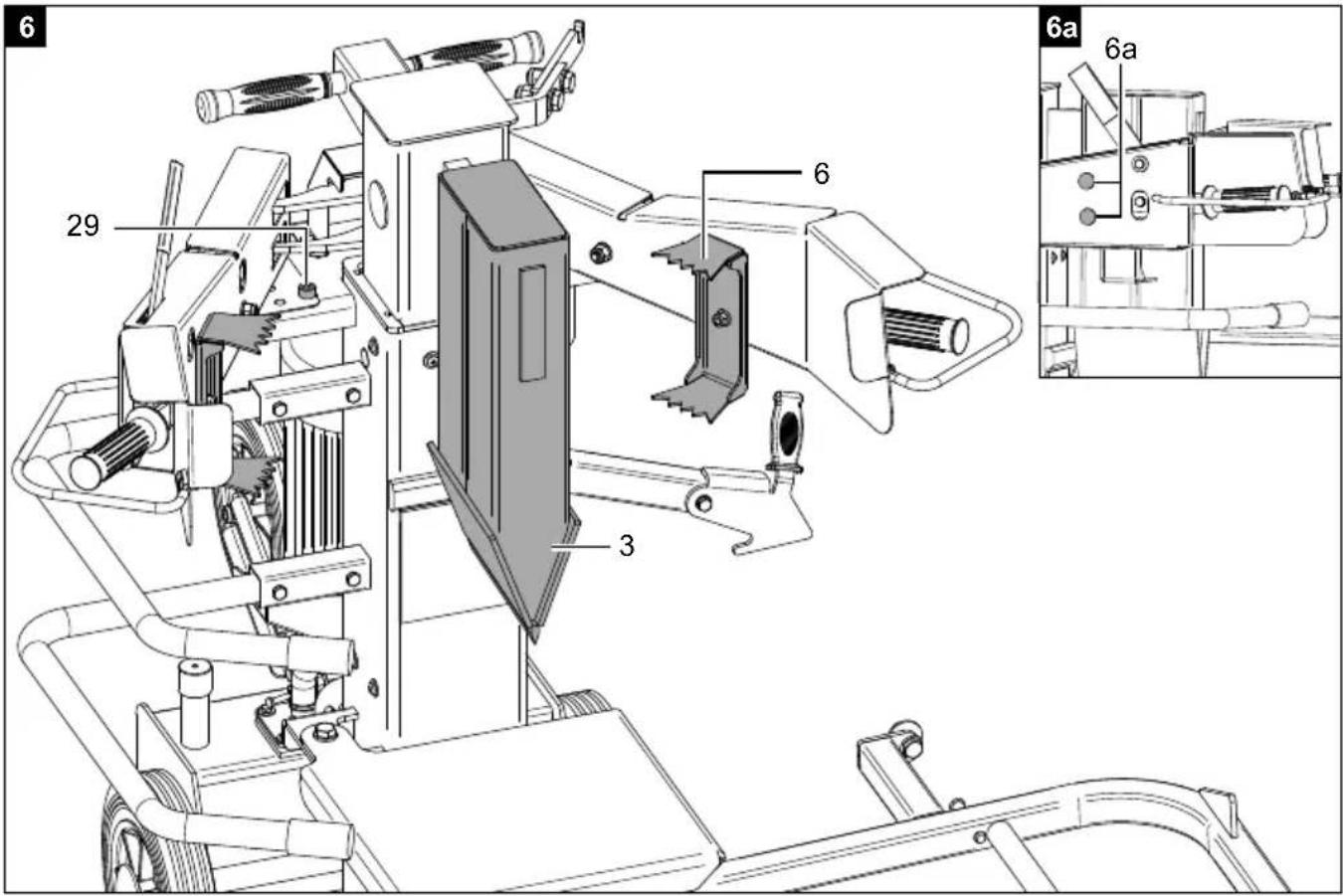
9.2 Fitting the retaining claw (6) (Fig. 6, 6a)
- To fit the retaining claws (6), you must first dismantle the upper locknut of the coach bolt using a 13mm open-ended spanner / socket spanner. To do this, hold the coach bolt through the hole (6a) with a finger so that it does not fall into the tube.
- Place the retaining claw (6) on the upper coach bolt and turn the locknut two turns (do not tighten).
- Repeat the process with the bottom coach bolt.
- Tighten the locknuts with a 13mm open-ended spanner / socket spanner.
- If necessary, adjust the stop screws (29) on both sides with an 8 mm Allen key such that the retaining claws (6) do not touch the splitting wedge (3).
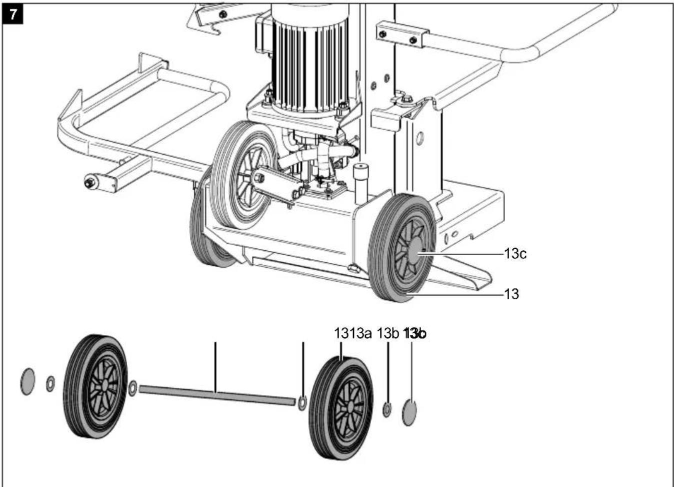
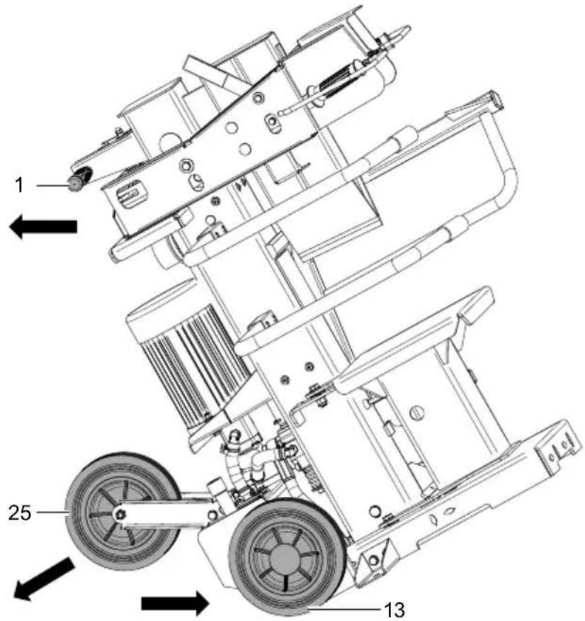
9.3 Fitting the transport wheels (13) (Fig. 7)
- To mount the transport wheels (13), you must first pre-assemble one side of the wheel axle (13a).
- To do this, take a wheel cap (13c) and place it on a wooden base.
- Place the wheel axle (13a) in the wheel cap (13c) and hit the wheel axle (13a) with a soft-face hammer until the hub cap (13c) is fixed.
- Now fit a 25mm washer (13b), a transport wheel (13) and a 25mm washer (13b) on the wheel axle (13a).
-
Slide the wheel axle (13a) through the holes on the bottom, rear end of the log splitter.
-
On the opposite side, fit a 25mm washer (13b), a transport wheel (13) and a 25mm washer (13b) on the wheel axle (13a).
- Fix the wheel cap (13c) by e.g. placing a socket spanner attachment 32mm on the wheel cap (13c) and hitting it with a soft-face hammer. Make sure that you counterhold the wheel axle (13a) on the other side.
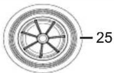
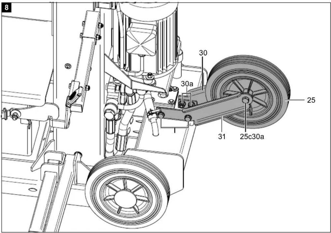
9.4 Fitting the support wheel (25) (Fig. 8)
- Fit the wheel holder right (30) and the wheel holder left (31) to the holders with two hexagon bolts M10x25mm (30a), washers and lock nuts each, do not tighten the hexagon bolts M10x25mm (30a) yet. Use two 16mm open-ended spanners / socket spanners.
- insert the socket (25a) through the support wheel (25).
- Fit the support wheel (25) between the wheel holder on the right (30) and the wheel holder on the left (31).
- Put a hexagon bolt M12x85mm (25c) and a washer M12 (25b) through the wheel holder left (31) and the socket (25a).
- Fix the hexagon bolt M12x85mm (25c) with a washer M12 (25b) and a lock nut to the wheel holder on the right (30). Use two 19mm open-ended spanners / socket spanners.
- Tighten the four hexagonal bolts M10x25mm (30a) of the wheel holder right (30) and the wheel holder left (31). Use two 16mm open-ended spanners / socket spanners.
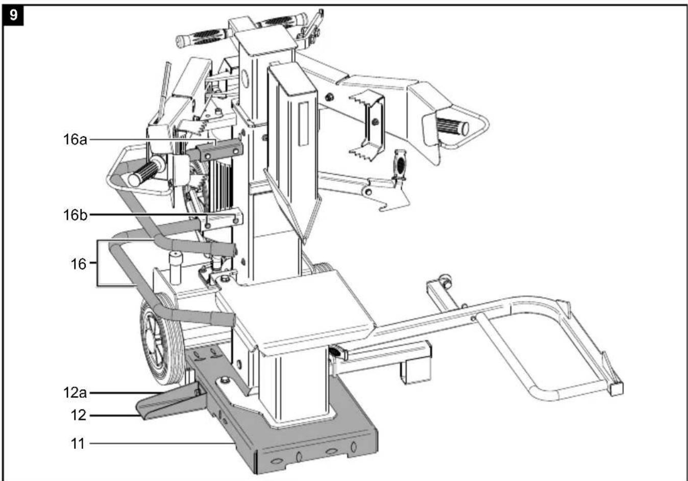
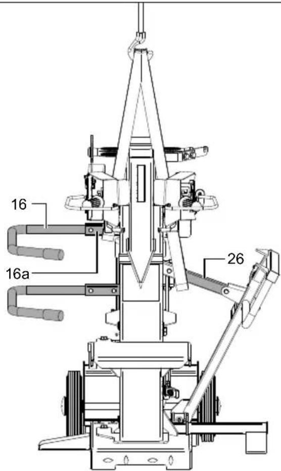
9.5 Mounting the protective frame (16) (Fig. 9)
- Push the bars of the protective frame (16) into the mounts (16a).
- Insert the hexagonal bolts M8x50mm (16b) with a washer through each of the holes.
- Secure the hexagonal bolts M8x50mm (16b) with one washer and one locknut each. Use two 13mm open-ended spanners / socket spanners.
- Fit the second protective bar (16) in the same way.
9.6 Fitting the supports (12) (Fig. 9)
- Take the supports (12) and fix them to the base plate (11) with the M10x25mm hexagonal bolts (12a) and a washer for each. Use a 16mm open-ended spanner / socket spanner.
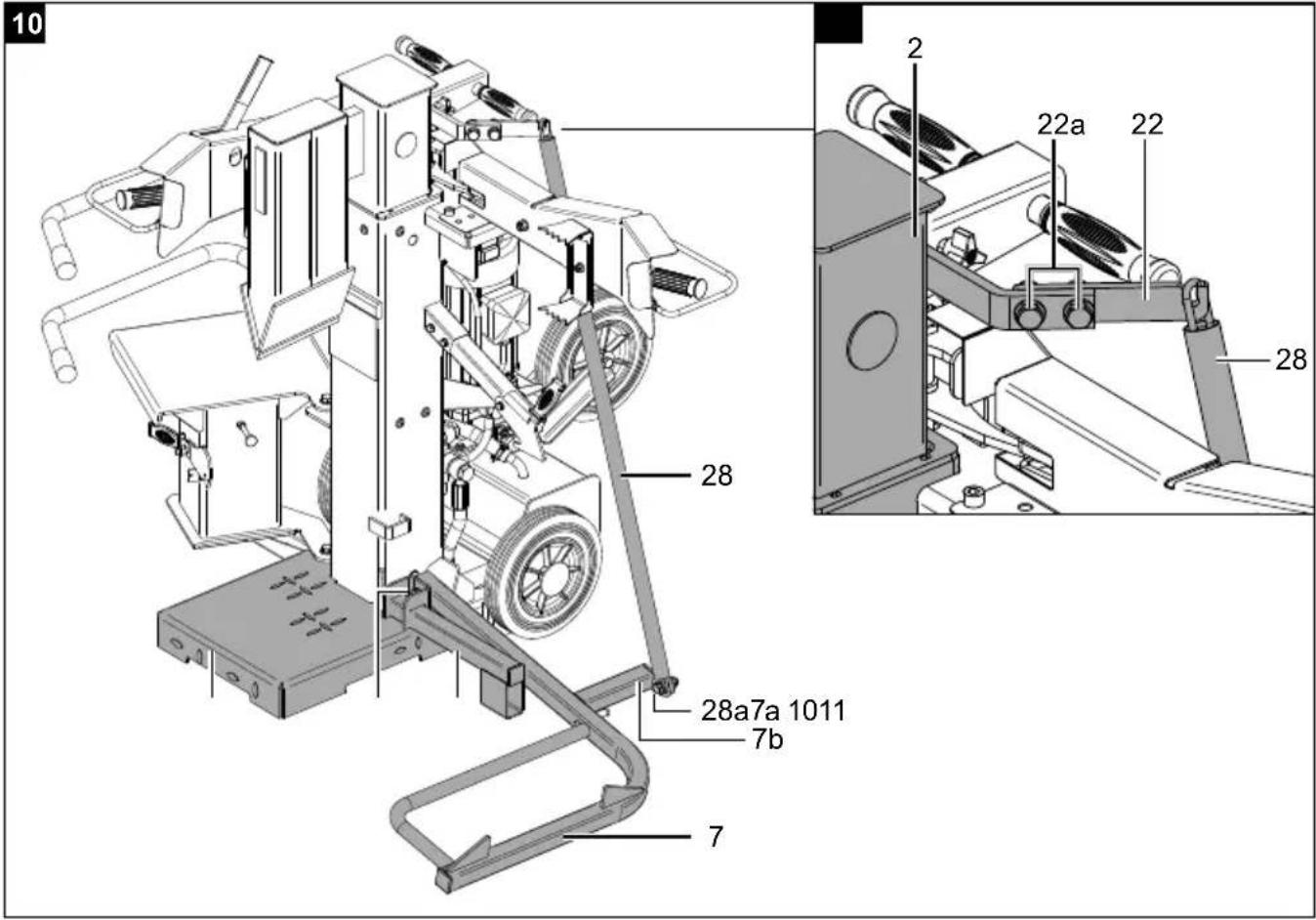
9.7 Fitting the chain hook (22) (Fig. 10a)
- Mount the chain hook (22) to the holder on the splitting column (2) with two hexagon bolts M12x40mm (22a), washers and lock nuts. Use two 19mm open-ended spanners / socket spanners.
9.8 Fitting the trunk lifter (7) (Fig. 10)
Note: The chain of the trunk lifter may only be attached to the chain hook using the last link for safety reasons.
- Mount the log lifter (7) with a hexagon bolt M12x70mm (7a), washer and lock nut to the holder of the base plate (11), the lock nut must be on the right side (towards the wheels)! Use two 19mm open-ended spanners / socket spanners.
- Slide the log lift support (10) into the recess. Fix the log lift support (10) with a hexagon socket screw M6x10mm (10a).
- Attach the chain (28) to the log lifter (7) in the following order: Hexagon bolt M12x40mm (28a), washer, log lifter bracket (7b), washer, chain (28), washer and lock nut. Screw on the lock nut only so far that the chain (28) can move freely. Attention! The chain (28) must turn completely smoothly on the hexagon head screw M12x40mm (28a)!
- Hang the end of the chain in the chain hook (22).
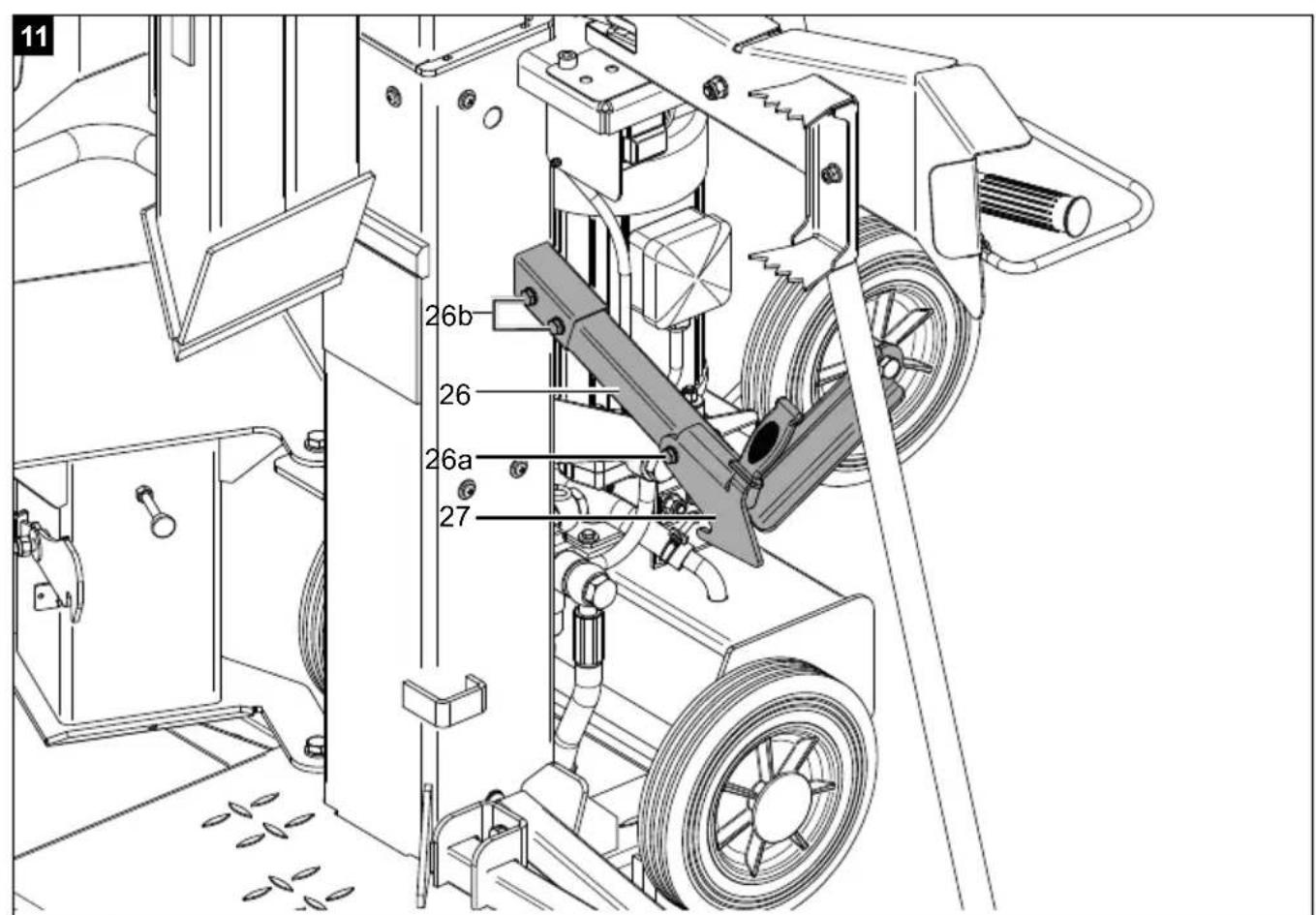
9.9 Fitting the trunk lifter lock (26) (Fig. 11)
- Mount the lever (27) with a hexagon bolt M8x55mm (26a), washer and lock nut to the trunk lift lock (26). Use two 13mm open-ended spanners / socket spanners.
- Slide the trunk lift latch (26) into the holder.
- Insert the hexagonal bolts M8x55mm (26b) with a washer through each of the holes.
- Secure the hexagonal bolts M8x55mm (26b) with one washer and one locknut each. Use two 13mm open-ended spanners / socket spanners.
- Check the ease of the lever (27).
10. Before commissioning
⚠ Attention!
Always make sure the product is fully assembled before commissioning!
Attention!
Before performing setting or maintenance work, unplug the mains plug!
⚠ WARNING!
Health hazard!
Inhalation of oil vapours and exhaust gases can cause serious damage to health, unconsciousness and in extreme cases death.
- Do not breathe in oil vapours and exhaust gases.
- Operate the device outdoors only.
NOTE!
Product damage
If the product is operated without or with too little hydraulic oil, this can lead to hydraulic pump damage.
NOTE!
Environmental damage!
Spilled oil can pollute the environment permanently.
The liquid is highly toxic and can quickly lead to water pollution.
- Fill/empty oil only on level, paved surfaces.
- Use a filling nozzle or funnel.
- Collect drained oil in a suitable container.
- Wipe up spilled oil carefully immediately and dispose of the cloth according to local regulations.
- Dispose of oil as per local regulations.
Before each use, always check:
- the connection cables for defective areas (cracks, cuts and the like),
• The device for possible damage,
• whether all screws are tightened,
• The hydraulic system for leaks, - The oil level
• The safety devices and - the ON/OFF switch.
Environmental conditions
The product must work under the following environmental conditions:
| Mini-mum | Maxi-mum | Recommended | |
| Temper-ature | 5°C 40°C | 16°C | |
| Humidity 95% 70% | |||
When working below 5^ C, the device should be idled for approx. 15 minutes to allow the hydraulic oil to warm up.
- The mains power connection is protected with a 16A slow-blow fuse.
- The "RCD circuit breaker" must have a 30mA trip rating.
Required accessories:
- Grease or spray oil
Not included in the scope of delivery.
10.1 Setting up the log splitter △ Attention!
Risk of injury from the log splitter tipping over. A toppling log splitter can cause serious injuries and damage.
Prepare the workplace where the device is to be located:
- Create enough space to allow safe, trouble-free working.
- The device is designed for working on level surfaces and must be set up securely on a level and firm surface.
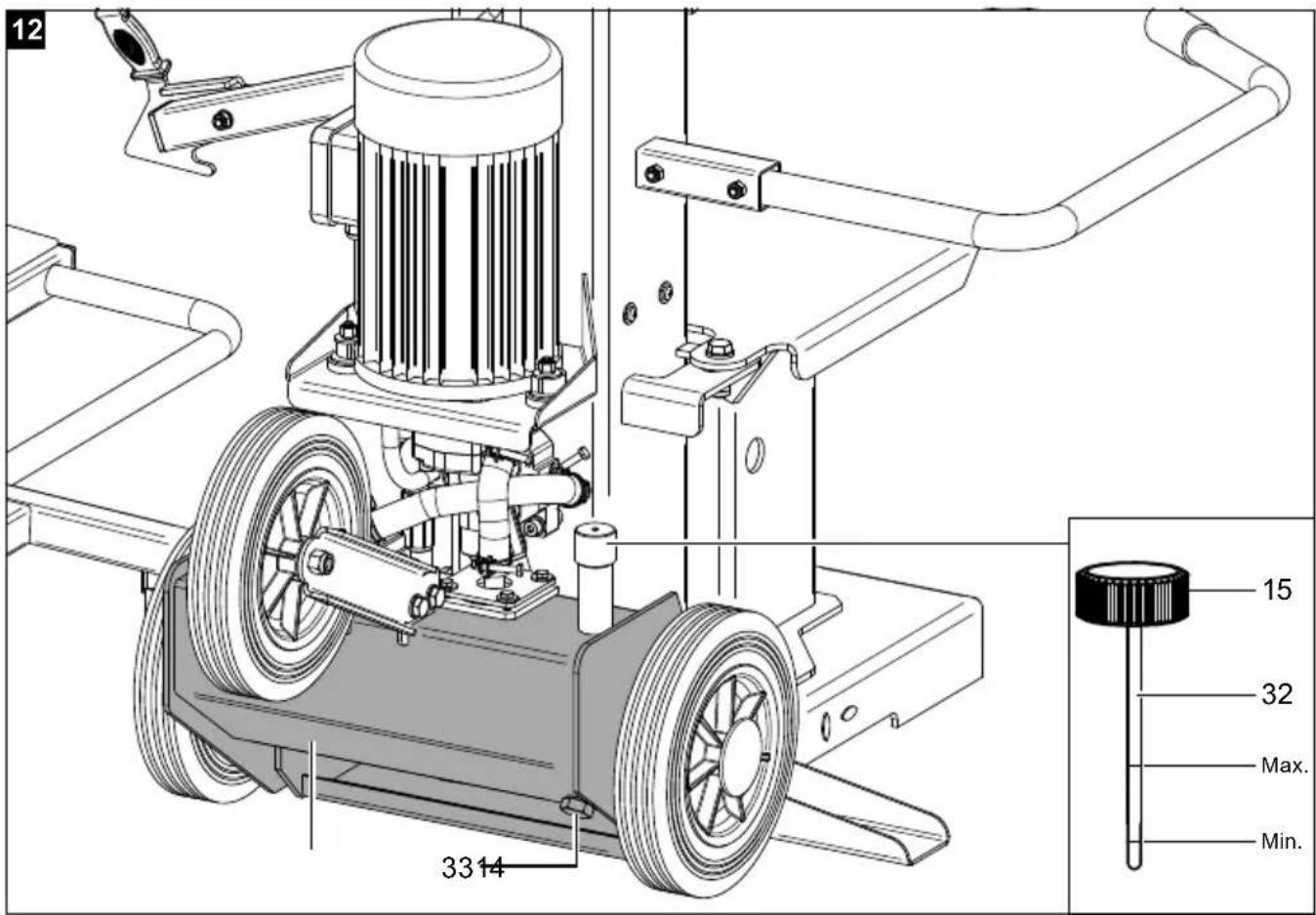
10.2 Checking the oil level (Fig. 1, 12)
Attention!
Check the oil level prior to commissioning!
The hydraulic system is a closed system with an oil tank, oil pump and control valve. There is already oil in the system when delivered. Check the oil level before the initial commissioning and regularly before commissioning. An oil level that is too low can damage the oil pump, refill with oil if necessary.
Note
The splitting column (2) must be retracted before the check, the device must be level.
- Unscrew the bleed screw (15).
- Wipe the oil dipstick (32) with a clean, lint-free cloth.
- Screw the bleed screw (15) back into the filler neck until it reaches the stop.
- Unscrew the bleed screw (15) and read the oil level in the horizontal position. The oil level must be between min. and max. at the dipstick (32).
- If the oil level is too low, top up as described in section 12.5.
- Then screw the bleed screw (15) back in.
10.3 Bleeding the hydraulic oil tank (14) (Fig. 12) ⚠ Attention!
Bleed the hydraulic tank before starting the log splitter.
Note
If the hydraulic tank (14) is not bled, the trapped air will damage the seals and therefore the log splitter!
- Before starting work, it is essential to loosen the bleed screw (15) by two turns to ensure air circulation in the hydraulic oil tank (14).
- Leave the bleed screw (15) loose during operation.
- Before you move the log splitter, close the bleed screw (15) again, since oil can run out otherwise.
Attention!
- When working below 5°C, the device should be idled for approx. 15 minutes to allow the hydraulic oil to warm up.
- Before transporting the device, it is essential to tighten the bleed screw to prevent oil leakage.
Functional check
Carry out a functional check before every use.
Action Result
| Press the control lever on the right (5) and the control lever on the left (18) down. | The splitting wedge (3) drives down. |
| Release the right operating lever (5) or the left operating lever (18). | The splitting wedge (3) remains in the selected position. |
| Release the control lever on the right (5) and the control lever on the left (18). | Splitting wedge (3) moves back to the upper position. |
| Actuate the stop lever lever (21). | The splitting wedge (3) remains in the selected position. |
10.4 Greasing the splitting column (2) (Fig. 1) ⚠ Attention!
Do not run the splitting column dry.
Generously grease the splitting column (2) of the log splitter before putting it into operation. This process must be repeated every 5 operating hours.
- The splitting column (2) must be in the top position.
- Apply a generous film of grease or spray oil to the splitting column (2).
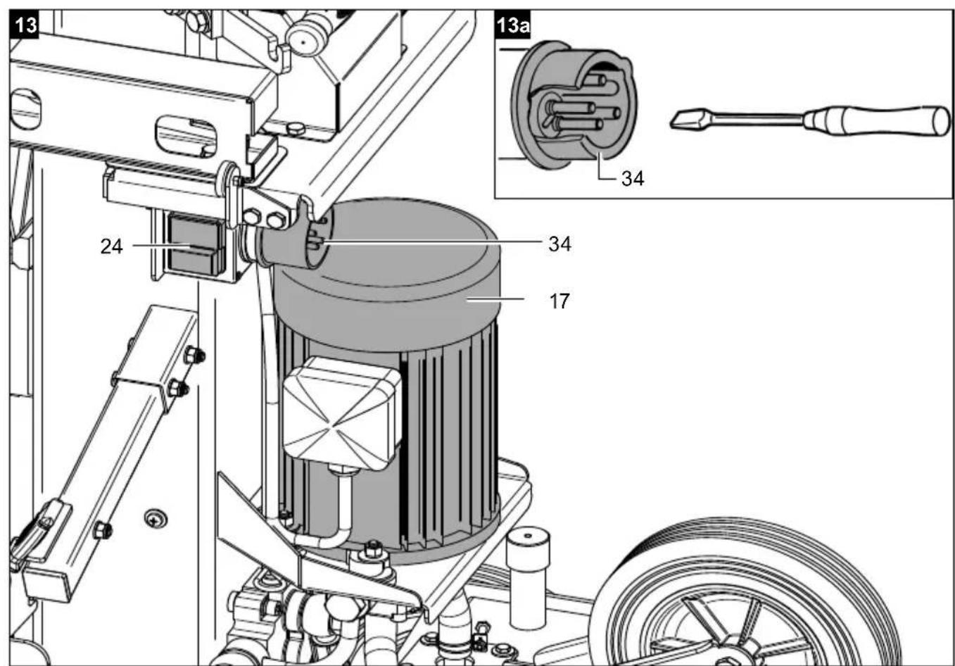
10.5 Switching on/off (Fig. 13)
Note:
Check the function of the on/off switch by switching it on and off again once before each use.
- Connect the electrical power connection (34) to the mains socket.
- To switch on, press the green button on the on/off switch (24), the device switches on.
- To switch off, press the red button on the on/off switch (24), the device switches off.
- Disconnect the electrical power connection (34) from the mains socket when you want to finish work.
10.6 Check the direction of rotation of the motor (17) (Fig. 1, 13, 13a)
Attention!
The direction of rotation of 3-phase motors must be checked when they are connected for the first time or if they are relocated. If necessary the polarity must be changed with the phase inverter.
- Switch the motor (17) on (see section 10.5).
- If the correct running direction is set, the splitting column (2) automatically moves upwards.
- If the splitting column (2) does not move, switch the device off immediately. Make sure that the stop lever (21) is released.
- Change the direction of rotation of the phase inverter with a screwdriver (not included in the scope of delivery) in the power connection (34).
⚠ Attention!
Never allow the motor to run with the wrong direction of rotation! This will inevitably lead to the destruction of the hydraulic system and no warranty claim can be made for this.
11. Operation
11.1 Splitting logs
WARNING!
Danger of injury!
Dry and seasoned wood can explode during the splitting process and injure the operator.
During the splitting process, bruising or severing of body parts may occur due to retracting of the riving knife.
Pieces of wood that are produced during a splitting process can fall down.
- Wear appropriate personal protective equipment.
Make sure that the wood to be split does not contain nails or foreign objects. The end of the log must be cut straight. Branches must be sawn off flush.
Pieces of wood cut at an angle can slip away during the splitting process. Only split timbers that have been sawn off straight.
11.2 Setting the stroke setting bar (fig. 1, 14, 14a)
- Move the splitting wedge (3) to the desired position using the control lever on the right (5) and the control lever on the left (18).
- Release the control lever on the left (18).
- Actuate the stop lever (21).
- Now release the operating lever right (5).
- Switch the motor (17) off (see section 10.5).
- Loosen the locking screw (stroke setting bar) (36).
- Guide the stroke setting bar with the cap nut (stroke setting bar) (35) upwards until the stroke setting bar is stopped on the stop.
- Tighten the locking screw (stroke setting bar) (36).
- Switch the motor (17) on (see section 10.5).
- Slowly release the stop lever (21) and check the top position of the splitting wedge (3).
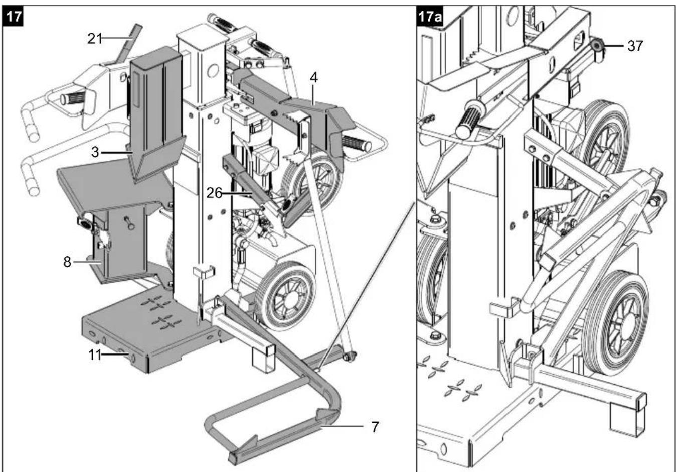
11.3 Operation of the log lifter (7) (Fig. 17, 17a)
- Swivel the swivel table (8) to the side with your foot.
- Fold the operating arm on the right (4) backwards onto the magnetic stop (37).
- Release the log lifter lock (26) of the log lifter (7) so that the lifting tube can move freely.
- Lower the splitting wedge (3) until the log lifter (7) rests completely on the ground.
- Roll the material to be split onto the log lifter (7) and the base plate (11). The splitting material must lie between the two fixings of the log lifter (7).
- Actuate the stop lever (21).
- Switch the motor (17) on (see section 10.5).
- Slowly loosen the stop lever (21).
- The trunk lifter (7) moves upwards and positions the log on the base plate (11).
- Make sure that the log is placed centrally to the splitting wedge (3).
- Split the split material. Proceed as described in section 11.4.
11.4 Splitting long logs (Fig. 1)
- Swivel the swivel table (8) to the side with your foot.
-
Place the log straight on the base plate (11).
-
Hold the splitting material with the two retaining claws (6) on the operating arm on the right (4) and the operating arm on the left (19). Make sure that the log is placed centrally to the splitting wedge (3).
- Press down the control lever on the right (5) and the control lever on the left (18) simultaneously.
- Move the operating arm on the right (4) and the operating arm on the left (19) approx. 2 cm away from the splitting material as soon as the splitting wedge (3) penetrates. This prevents damage to the retaining claws (6).
- Drive the splitting wedge (3) down until the log is split.
- If the log has not been completely split during the first splitting stroke, proceed as described in section 11.6.
11.5 Starting position log lifter (7) (Fig. 17, 17a) Note
This is used as a second guard arm when not using the trunk lifter.
- Put the trunk lifter (7) in the resting position.
- Secure the log lifter (7) with the log lifter lock (26).
11.6 Remove jammed log (Fig. 1)
Note:
Split through jammed wood using the swivel table, knock it out against the splitting direction or remove it by moving the splitting wedge upwards.
ATTENTION!
Danger of injury!
The swivel table must engage in the locking hook!
ATTENTION!
Danger of injury!
There is a danger of knotty logs becoming jammed during the splitting process. Please note that the wood is under a lot of tension when it is removed and parts of your body can be crushed in the split crack.
- Do not reach into the log splitter when it is running.
- Do not put any objects into the log splitter while it is running (e.g. hammer or similar).
-
If the log is not completely split during the first splitting stroke, carefully move the splitting wedge (3) with the log to the upper position using the control lever on the right (5) and the control lever on the left (18).
-
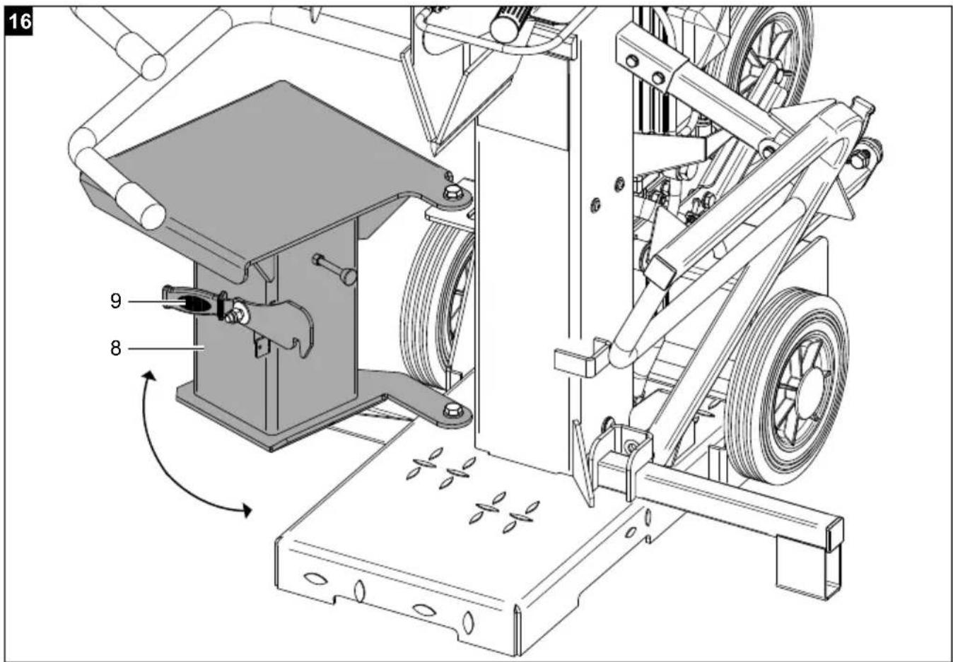
Swivel in the swivel table (8) by foot until the locking hook (9) engages.
- Now carry out a second splitting stroke until the log is completely split.
- Remove the log and swivel the swivel table (8) away with your foot.
11.7 Restart protection in the event of a power failure (zero voltage trigger)
In the event of a power failure, unintentional removal of the plug or a defective fuse, the device switches off automatically.
To switch on again, proceed as described in section 10.5.
11.8 End of work (Fig. 1, 12)
- Move the splitting column (2) to the bottom position.
- Release the control lever on the left (18).
- Actuate the stop lever (21).
- Switch off the motor (17) (see section 10.5) and disconnect the mains plug.
- Swivel in the swivel table (8) by foot until the locking hook (9) engages.
- Close the bleed screw (15).
- Protect the device from moisture!
- Observe the general maintenance information.
12. Maintenance and repairs
⚠ WARNING!
Danger of injury!
The device can start unexpectedly and cause injuries.
- Switch the motor off before performing any maintenance work.
- Disconnect the mains plug before carrying out any maintenance work.
⚠ WARNING!
Health hazard!
Inhalation of oil vapours can cause serious damage to health, unconsciousness and in extreme cases death.
- Do not inhale oil vapours.
- Operate the device outdoors only.
NOTE
Product damage
If the product is operated without or with too little hydraulic oil, this can lead to hydraulic pump damage.
NOTE!
Environmental damage!
Spilled oil can pollute the environment permanently.
The liquid is highly toxic and can quickly lead to water pollution.
- Fill/empty oil only on level, paved surfaces.
- Use a filling nozzle or funnel.
- Collect drained oil in a suitable container.
- Wipe up spilled oil carefully immediately and dispose of the cloth according to local regulations.
- Dispose of oil as per local regulations.
All protective and safety equipment must be reassembled immediately after repair, maintenance is completed.
Our recommendation to you:
Clean the device thoroughly after each use using a damp cloth and a little soft soap. Do not use any cleaning products or solvents; they could attack the plastic parts of the device. Make sure that no water can penetrate the interior of the device.
Tool required:
- 1x open-ended spanner / socket spanner, size 24mm
- Funnel
- Drip tray
- File / angle grinder
Not included in the scope of delivery.
12.1 Splitting wedge (3) (Fig. 1)
- The splitting wedge (3) is a wearing part that should be reground with a file or angle grinder or replaced with a new splitting wedge (3) if necessary.
12.2 Operating arms (4, 19) and operating levers (5, 18) (Fig. 1)
- The combined retaining and control device must remain smooth-running. Lubricate with a few drops of oil as required.
12.3 Splitting column (2) (Fig. 1)
-
Keep the splitting column (2) clean. Remove fouling, wood chips, bark, etc.
-
Lubricate splitting column (2) with spray oil or grease.
12.4 Check the oil level regularly!
An oil level that is too low will damage the oil pump! (See 10.2)
- Check the hydraulic connections and screw connections for leaks regularly and retighten them if necessary.
12.5 Topping up the hydraulic oil (Fig. 1, 12)
We recommend oil from the HLP 32 range.
Note:
The splitting column (2) must be retracted before the check, the device must be level.
- Unscrew the bleed screw (15).
-
Top up the hydraulic oil with the help of a suitable funnel. Note the max. filling capacity of 8 l. Carefully fill the oil up to the lower edge of the filling port.
-
Wipe the oil dipstick (32) with a clean, lint-free cloth.
-
Screw the bleed screw (15) back into the filler neck until it reaches the stop.
-
Unscrew the bleed screw (15) and read the oil level in horizontal position The oil level must be between min. and max. at the dipstick (32).
-
If the oil level is too low, repeat the process.
-
Then screw the bleed screw (15) back in.
12.6 Changing the hydraulic oil (Fig. 1, 12)
Change hydraulic oil after 50 hours of operating time. Every 500 hours thereafter.
Note
The hydraulic oil change should be carried out while the motor is at operating temperature.
Note
The splitting column (2) must be retracted before the oil change and the product must be level.
-
Position a suitable collecting container with min. 10 litre volume.
-
Unscrew the bleed screw (15).
-
Remove the oil drain screw (33) with a 24mm open-ended spanner to let the oil drain out.
-
Screw the oil drain screw (33) back in.
-
Fill up with new hydraulic oil (approx. 8 litres).
-
Screw the bleed screw (15) back in.
-
Check the oil level as described in section 10.2.
-
Dispose of the used oil properly at a local used oil collection point.
The time intervals cited here relate to normal operating conditions. If the device is subjected to heavier loads, these times must be reduced accordingly.
Service information
With this product, it is necessary to note that the following parts are subject to natural or usage-related wear, or that the following parts are required as consumables.
Wearing parts*: Splitting wedge, splitting wedge/riving spar guides, hydraulic oil
* may not be included in the scope of delivery!
Spare parts and accessories can be obtained from our Service Centre. To do this, scan the QR code on the front page.
13. Storage
Note
Move the splitting column into the bottom position (see section 11.8).
Store the device and its accessories in a dark, dry and frost-free place that is inaccessible to children. The optimum storage temperature is between 5 and 30°C. Store the product in its original packaging. Cover the product to protect it from dust or moisture. Store the operating manual with the product.
14. Transport
⚠ Attention!
Disconnect the mains plug before transport.
Attention!
Do not transport the device lying on its side!
Note
Move the splitting column into the bottom position (see section 11.8).
14.1 Transport with transport handle (1) (Fig. 18)
The log splitter is equipped with two transport wheels (13), a support wheel (25) and a transport handle (1) for easy transport.
- In order to transport the device, hold the transport handle (1) with one hand and tilt the log splitter slightly with your foot.
- The log splitter tilts on the support wheel (25) and the transport wheels (13) and can thus be moved away.
14.2 Transport by crane (Fig 19)
⚠ Attention!
Never lift on the riving knife!
- Attach the transport straps (not included) to the upper bracket (16a) of the guard rail (16) and to the bracket of the log lifter lock (26).
- Lift the device up carefully.
15. Electrical connection
The electrical motor installed is connected and ready for operation. The connection complies with the applicable VDE and DIN provisions.
The customer's mains connection as well as the extension cable used must also comply with these regulations.
Use a portable safety switch (PRCD) if the residual current protective circuit (RCD) in the mains power supply is not provided with a rated residual current of no more than 30 mA.
The mains power connection is protected with a 16 A slow-blow fuse.
Damaged electrical connection cables
The insulation on electrical connection cables is often damaged.
This may have the following causes:
- Pressure points, where connection cables are passed through windows or doors.
- Kinks where the connection cable has been improperly fastened or routed.
- Places where the connection cables have been cut due to being driven over.
• Insulation damage due to being ripped out of the wall outlet. - Cracks due to the insulation ageing.
Such damaged electrical connection cables must not be used and are life-threatening due to the insulation damage.
Check the electrical connection cables for damage regularly. Ensure that the connection cables are disconnected from electrical power when checking for damage.
Electrical connection cables must comply with the applicable VDE and DIN provisions. Only use connection cables with the designation H07RN-F.
The printing of the type designation on the connection cable is mandatory.
- The product fulfils the requirements of EN 61000-3-11 and is subject to special connection requirements. This means that use at any freely selectable connection points is not permitted.
- The device can cause temporary voltage fluctuations in unfavourable mains conditions.
- The product is intended exclusively for use at connection points which
a) do not exceed a maximum permitted mains impedance "Z"
$$ (Z \max = 0. 3 3 0 \Omega (4 0 0 V)), \text { or } $$
b) have a continuous current carrying capacity of the mains of at least 100 A per phase.
- As the user, you are required to ensure, in consultation with your electric power company if necessary, that the connection point at which you wish to operate the product meets one of the two requirements, a) or b), named above.
Three-phase motor 400 V 3\~ / 50 Hz Mains voltage 400 V 3N\~ / 50 Hz
Mains power connection and extension leads must be 5-core = 3\~ + N + PE.
- Extension cables must have a minimum cross section of 1.5 ~mm^2 (≤ 25 ~m) .
- Extension cables must have a minimum cross section of 2.5 ~mm^2 (>25 ~m) .
Connections and repair work on the electrical equipment may only be carried out by electricians.
Please provide the following information in the event of any enquiries:
• Type of current for the motor
• Machine data - type plate
- Motor data - type plate
16. Disposal and recycling
Notes for packaging


The packaging materials are recyclable. Please dispose of packaging in an environmentally friendly manner.
Notes on the electrical and electronic equipment act [ElektroG]
![SCHEPPACH Compact 15t - Notes on the electrical and electronic equipment act [ElektroG] - 1](/content/2026/04/668415/images/2b446d67ae81128adef4aad741ca2ba6c354108fa579a8269d58bc874daed7c7.jpg)
Electrical and electronic appliances do not belong in household waste, but should be collected and disposed of separately.
- Used batteries or rechargeable batteries that are not installed permanently in the old appliance must be removed non-destructively before disposal. Their disposal is regulated by the battery act.
- Owners or users of electrical and electronic devices are legally obliged to return them after use.
- The end user is responsible for deleting their personal data from the old device being disposed of!
- The symbol of the crossed-out dustbin means that waste electrical and electronic equipment must not be disposed of with household waste.
-
Waste electrical and electronic equipment can be handed in free of charge at the following places:
-
Public disposal or collection points (e.g. municipal works yards).
- Points of sale of electrical appliances (stationary and online), provided that dealers are obliged to take them back or offer to do so voluntarily.
- Up to three waste electrical devices per type of device, with an edge length of no more than 25 centimetres, can be returned free of charge to the manufacturer without prior purchase of a new device from the manufacturer or taken to another authorised collection point in your vicinity.
-
For additional take-back conditions of the manufacturers and distributors, please contact the respective customer service.
-
In the case of delivery of a new electrical device by the manufacturer to a private household, the latter may arrange for the free collection of the old electrical device upon request from the end-user. Get in contact with the manufacturer's customer service.
- These statements only apply to devices installed and sold in the countries of the European Union and which are subject to the European Directive 2012/19/EU. Different provisions may apply to the disposal of electrical and electronic appliances in countries outside the European Union.
Contact your local refuse disposal authority for more details of how to dispose of your worn-out electrical devices.
Fuels and oils
- Before disposing of the unit, the fuel tank and the engine oil tank must be emptied!
- Fuel and engine oil do not belong in household waste or drains, but must be collected or disposed of separately!
- Empty oil and fuel tanks must be disposed of in an environmentally friendly manner.
17. Troubleshooting
The following table shows fault symptoms and describes remedial measures in the event of your machine failing to work properly. If you cannot localise and rectify the problem with this, please contact your service workshop.
| Fault Possible cause Remedy | ||
| The motor (17) ends the splitting process automatically. | Overvoltage protective device was triggered. | Call a qualified electrician. |
| Log is not split. | Log splitter loaded incorrectly. Insert the log correctly. | |
| Splitting wedge (3) is blunt. Grind the splitting | wedge (3). | |
| Oil leaks. Locate the leak, contact the dealer. | ||
| Splitting column (2) vibrates, generates noises. | Low oil and excess air in the hydraulic system. | Check the oil level, top up if necessary, otherwise contact the dealer. |
| Hydraulic pump whistles. | Too little hydraulic oil in the hydraulic oil tank (14). | Top up hydraulic oil. |
| Oil leakage at splitting column (2) or in other places. | Trapped air in the hydraulic system during operation. | Loosen the bleed screw (15) two turns before use. |
| Bleed screw (15) not tightened before transport. | Tighten bleed screw (15) before transport. | |
| Oil drain screw (33) loose. Tighten the oil drain | screw (33) firmly. | |
| Oil valve and/or seals defective. Contact dealer. | ||
Günzburger Straße 69
D-89335 Ichenhausen
Cher client,
Günzburger Straße 69
D-89335 Ichenhausen
Egregio cliente,
Günzburger Straße 69
D-89335 Ichenhausen
Geachte klant,
11.4 Langhout splijten (afb. 1)
12.1 Splijtwig (3) (afb. 1)
14.1 Transport via transportgreep (1) (afb. 18)
Günzburger Straße 69
D-89335 Ichenhausen
Estimado cliente:
Günzburger Straße 69
D-89335 Ichenhausen
Estimado cliente,
Günzburger Straße 69
D-89335 Ichenhausen
Vážený zákazníku,
Günzburger Straße 69
D-89335 Ichenhausen
Vážený zákazník,
Günzburger Straße 69
D-89335 Ichenhausen
Kedves Ügyfelünk!
Günzburger Straße 69
D-89335 Ichenhausen
Szanowny Kliencie,
Günzburger Straße 69
D-89335 Ichenhausen
Poštovani kupci,
Günzburger Straße 69
D-89335 Ichenhausen
Spoštovani kupec,
želimo vam veliko veselja in uspeha pri delu z vašo novo napravo.
Napotek:
Günzburger Straße 69
D-89335 Ichenhausen
Austatud klient!
9.6 Toe (12) monteerimine (joon. 9)
Günzburger Straße 69
D-89335 Ichenhausen
Gerbiamas kliente,
Günzburger Straße 69
D-89335 Ichenhausen
Godātais klient!
Günzburger Straße 69
D-89335 Ichenhausen
Bästa kund!
Günzburger Straße 69
D-89335 Ichenhausen
Arvoisa asiakas,
Günzburger Straße 69
D-89335 Ichenhausen
Kære kunde,
Günzburger Straße 69
D-89335 Ichenhausen
Kjære kunde,
Günzburger Straße 69
D-89335 Ichenhausen, Германия
Уважаеми клиенти,
Günzburger Straße 69
D-89335 Ichenhausen
Αξιότιμε πελάτη,
Günzburger Straße 69
D-89335 Ichenhausen
Stimate client,
Günzburger Straße 69
D-89335 Ichenhausen
Poštovani kupče,
Günzburger Straße 69
D-89335 Ichenhausen
İthalatçı:
400 V
Hydraulik
flowchart
graph TD
    A["Actuator"] --> B["Pump"]
    B --> C["Tank"]
    C --> D["Pressure Gauge"]
    D --> E["Mump"]
    style A fill:#f9f,stroke:#333
    style B fill:#ccf,stroke:#333
    style C fill:#cfc,stroke:#333
    style D fill:#fcc,stroke:#333
    style E fill:#cff,stroke:#333
EU Declaration of Conformity
| 2000/14/EG_2005/88/EG | |
| Noise: measured LWA = xx dB; guaranteed LWA = xx dB | |
| Annex V | |
| Annex VI | |

| 2016/1628/EU | |
| Emission. No: |
Standard references:
This declaration of conformity is issued under the sole responsibility of the manufacturer.
The object of the declaration described above fulfils the regulations of the directive 2011/65/EU of the European Parliament and Council from 8th June 2011, on the restriction of the use of certain hazardous substances in electrical and electronic equipment.
Subject to change without notice
Documents registrar: Andreas Pecher Günzburger Str. 69, D-89335 Ichenhausen
EU Declaration of Conformity
Standard references:
The object of the declaration described above fulfils the regulations of the directive 2011/65/EU of the European Parliament and Council from 8th June 2011, on the restriction of the use of certain hazardous substances in electrical and electronic equipment.
Subject to change without notice
Documents registrar: Andreas Pecher
Günzburger Str. 69, D-89335 Ichenhausen
EU Declaration of Conformity
AB uygunluk beyanı
CE
Scheppach GmbH, Günzburger Str. 69, D-89335 Ichenhausen
| DE | erklärt folgende Konformität gemäß EU-Richtlinien und Normen für den Artikel | RO | declară următoarea conformitate corespunzător directivelor și normelor UE pentru articolul |
| GB | hereby declares the following conformity under the EU Directive and standards for the following article | GR | δηλώνει την ακόλουθη συμμόρφωση σύμφωνα με την Οδηγία ΕΕ και τα πρότυπα για το προϊόν |
| BG | декларира съответното съответствие съгласно Дирек-тива на ЕС и норми за артикул | TR | Burada açıklanan ürünün geçerli yönetmeliklere ve standartlara uygun olduğunu tamamen kendi sorumluluğumuz altında beyan ediyoruz. |
| RS | potvrđuje sledeću usklađenost prema smernicama EZ i normama za artikal |
Article name: LOG SPLITTER - COMPACT 12T, 15T
Ürün Tanım: ODUN YARICI - COMPACT 12T, 15T
Standard references:
This declaration of conformity is issued under the sole responsibility of the manufacturer.
The object of the declaration described above fulfils the regulations of the directive 2011/65/EU of the European Parliament and Council from 8th June 2011, on the restriction of the use of certain hazardous substances in electrical and electronic equipment.
Subject to change without notice
Documents registrar: Andreas Pecher Günzburger Str. 69, D-89335 Ichenhausen
Garantie DE
Apparent defects must be notified within 8 days from the receipt of the goods. Otherwise, the buyer's rights of claim due to such defects are invalidated. We guarantee for our machines in case of proper treatment for the time of the statutory warranty period from delivery in such a way that we replace any machine part free of charge which provably becomes unusable due to faulty material or defects of fabrication within such period of time. With respect to parts not manufactured by us we only warrant insofar as we are entitled to warranty claims against the upstream suppliers. The costs for the installation of the new parts shall be borne by the buyer. The cancellation of sale or the reduction of purchase price as well as any other claims for damages shall be excluded.
Garantie FR
Apparent defects must be notified within 8 days from the receipt of the goods. Otherwise, the buyer's rights of claim due to such defects are invalidated. We guarantee for our machines in case of proper treatment for the time of the statutory warranty period from delivery in such a way that we replace any machine part free of charge which provably becomes unusable due to faulty material or defects of fabrication within such period of time. With respect to parts not manufactured by us we only warrant insofar as we are entitled to warranty claims against the upstream suppliers. The costs for the installation of the new parts shall be borne by the buyer. The cancellation of sale or the reduction of purchase price as well as any other claims for damages shall be excluded.
Záruka CZ
Apparent defects must be notified within 8 days from the receipt of the goods. Otherwise, the buyer's rights of claim due to such defects are invalidated. We guarantee for our machines in case of proper treatment for the time of the statutory warranty period from delivery in such a way that we replace any machine part free of charge which provably becomes unusable due to faulty material or defects of fabrication within such period of time. With respect to parts not manufactured by us we only warrant insofar as we are entitled to warranty claims against the upstream suppliers. The costs for the installation of the new parts shall be borne by the buyer. The cancellation of sale or the reduction of purchase price as well as any other claims for damages shall be excluded.
Garantii EE
Apparent defects must be notified within 8 days from the receipt of the goods. Otherwise, the buyer's rights of claim due to such defects are invalidated. We guarantee for our machines in case of proper treatment for the time of the statutory warranty period from delivery in such a way that we replace any machine part free of charge which provably becomes unusable due to faulty material or defects of fabrication within such period of time. With respect to parts not manufactured by us we only warrant insofar as we are entitled to warranty claims against the upstream suppliers. The costs for the installation of the new parts shall be borne by the buyer. The cancellation of sale or the reduction of purchase price as well as any other claims for damages shall be excluded.
