FBCC12TPDF - Log splitter SCHEPPACH - Free user manual and instructions
Find the device manual for free FBCC12TPDF SCHEPPACH in PDF.

| Brand | Scheppach |
| Model | FBCC12TPDF |
| Product type | Vertical hydraulic wood splitter |
| Power source | Tractor PTO (540 rpm) |
| Dimensions (L x W x H) | 1050 x 870 x 2280 mm |
| Weight | 167 kg |
| Permissible log length | 56 – 104 cm |
| Permissible log diameter | 10 – 30 cm |
| Max. splitting force | 10.8 t |
| Ram stroke | 850 mm |
| Advance speed (low/high) | 3.5 / 18.5 cm/s |
| Return speed | 4.5 cm/s |
| Hydraulic oil capacity | 7.5 L |
| Drive | PTO shaft (cardan) |
| Minimum tractor power | 5.2 HP |
| Usage | Vertical, splitting with the grain |
| Safety | Two-hand control, return yoke, claw, shaft guard |
| Maintenance | Drain hydraulic and transmission oil, check level |
| Wear parts | Guides, hydraulic oil, gear oil |
Frequently Asked Questions - FBCC12TPDF SCHEPPACH
User questions about FBCC12TPDF SCHEPPACH
0 question about this device. Answer the ones you know or ask your own.
Ask a new question about this device
Download the instructions for your Log splitter in PDF format for free! Find your manual FBCC12TPDF - SCHEPPACH and take your electronic device back in hand. On this page are published all the documents necessary for the use of your device. FBCC12TPDF by SCHEPPACH.
USER MANUAL FBCC12TPDF SCHEPPACH
natural_image
Technical line drawing of a mechanical device with articulated arms and levers (no text or symbols)FBCC12TPDF

| DE | MeterholzspalterOriginalbetriebsanleitung | 9 |
| GB | Metre log splitterTranslation of original instruction manual | 22 |
| FR | Fendeur de bûches d'un mètreTraduction des instructions d'origine | 34 |
1
2
natural_image
Technical line drawing of a mechanical press or drill press device with no visible text or symbols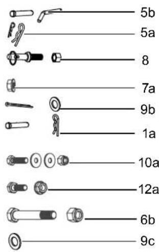
natural_image
Technical line drawing of a mechanical assembly with no visible text or symbols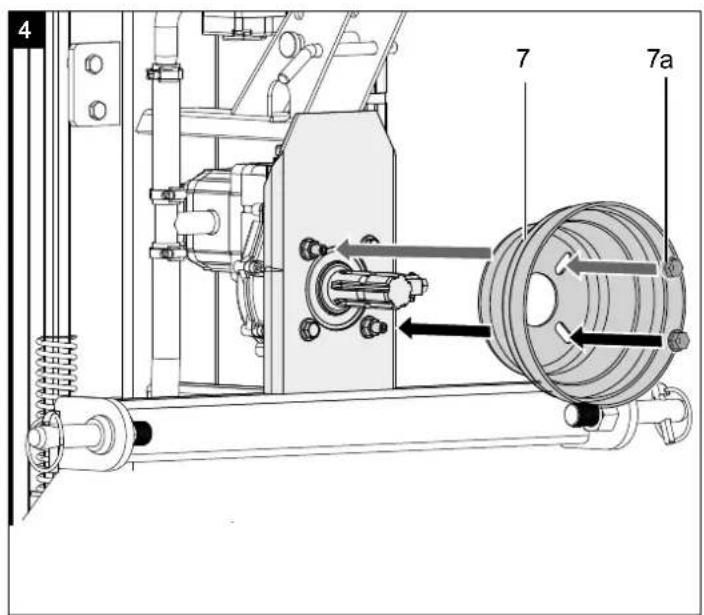

Günzburger Straße 69
D-89335 Ichenhausen
Verehrter Kunde,
Explanation of the symbols on the product
Symbols are used in this manual to draw your attention to potential hazards. The safety symbols and the accompanying explanations must be fully understood. The warnings themselves will not rectify a hazard and cannot replace proper accident prevention measures.
 | Read the manual before commissioning! |
 | Use safety shoes! |
 | Use work gloves! |
 | Use hearing protection and safety goggles! |
 | Keep the work area orderly! Disorder can lead to accidents! |
 | Dispose of used oil properly (on-site waste oil collection point). Dumping used oil in the soil or mixing it with waste is prohibited. |
 | Risk of slipping due to leaking oil. |
 | Removing or modifying protective or safety equipment is prohibited. |
 | Do not remove any jammed trunks with your hands. |
 | Danger of injury due to objects being flung away! |
 | Danger of cuts and crushing; never touch dangerous areas when the splitting blade is moving. |
 | Speed of the drive PTO shaft n = 540 rpm |
 | Do not use the product in wet conditions! |
 | Machine may only be operated by one person! |
 | Keep bystanders away from the work area. |
 | Avoid injuries caused by the moving splitting knife. |
 | Unplug the mains cable before carrying out cleaning or maintenance work. |
 | Do not transport the product lying down! |
 | Loosen the bleeder screw about 2 turns before starting work. Close before transport. |
 | Caution! Moving tools! |
 | Lifting point |
 | Lashing point for load securing |
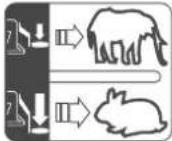 | Two operating speeds:1. Low speed and full splitting force2. High speed and reduced splitting force |
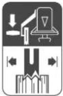 | Press the lever to fix the trunk in place with the claw. |
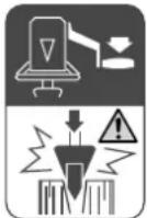 | Press the lever to split the log. |
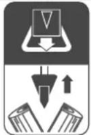 | Press the return bar to raise the splitting blade. |
 | The product complies with the applicable European directives. |
Table of contents: Page:
- Introduction......26
- Product description (fig. 1 - 19) ...... 26
- Scope of delivery (fig. 2)......26
- Proper use....27
- General safety instructions....27
- Additional safety instructions....28
- Technical data 28
- Unpacking 28
- Assembly / Before commissioning 29
- Start-up 29
- Cleaning 31
- Transport 31
- Storage 31
- Maintenance....31
- Disposal and recycling 32
- Troubleshooting....33
- Declaration of conformity 51
1. Introduction
Manufacturer:
Scheppach GmbH
Günzburger Straße 69
D-89335 Ichenhausen
Dear Customer,
We hope your new product brings you much enjoyment and success.
Note:
In accordance with the applicable product liability laws, the manufacturer of this product assumes no liability for damage to the product or caused by the product arising from:
- Improper handling
• Non-compliance with the operating manual
• Repairs carried out by third parties, unauthorised specialists
• Installing and replacing non-original spare parts - Improper use
- Failure of the electrical system in the event of the electrical regulations and VDE provisions 0100, DIN 57113 / VDE 0113 not being observed
Note:
The operating manual is part of this product. It includes important instructions for the safe, proper and economic operation of the product, for avoiding danger, for minimising repair costs and downtimes and for increasing the reliability and extending the service life of the product. In addition to the safety instructions in this operating manual, you must also observe the regulations applicable to the operation of the product in your country.
Familiarise yourself with all operating and safety instructions before using the product. Only operate the product as described and for the specified areas of application. Keep the operating manual in a good place and hand over all documents when passing the product on to third parties.
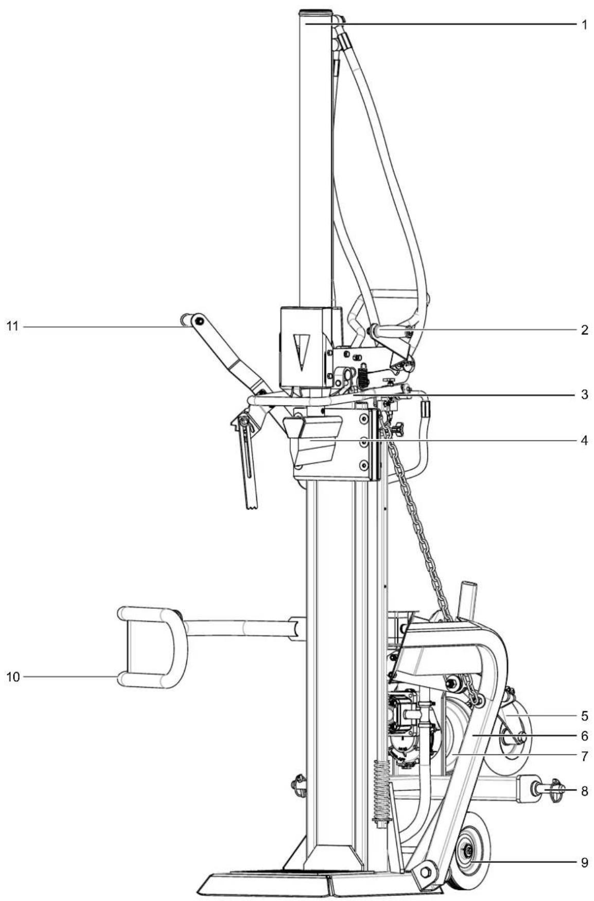
2. Product description (fig. 1 - 19)
- Cylinder
1a. Locking pin with split pin - Operating lever a
- Return bow
- Splitting blade
4a. Support - Additional transport wheel
5a. Locking bolt, locking pin and spring split pins
5b. Locking bolt and locking pin - Trunk lifter
6a. Chain
6b. M16 x 90 mm bolt with hex nut - Cardan shaft protective cap
7a. Collar nut M10
8. M22 three-point bolts with hex nut
9. Transport wheels
9a. Wheel axle
9b. Safety splint
9c. Washer
10. Retainer arm
10a. M10 x 35 mm bolt with washer and hex nut
11. Operating lever b
12. Retainer hook
12a. M10 x 30 mm bolt with collar nut
13. Operating manual
14. Claw
15. Dust cover
16. Upper mounting arm
16a. Hanger pin
16b. PTO shaft (metre log splitter)
16c. PTO shaft (drive)
17. Lower mounting arm
17a. Connecting pin
18. Oil filling opening
19. Oil drain screw
20. Oil filler plug
21. Oil drain screw (gearbox)
22. Oil-level window
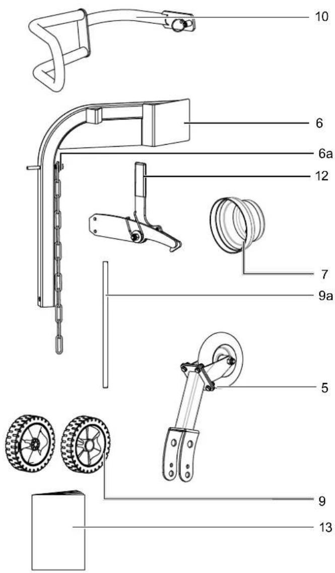
3. Scope of delivery (fig. 2)
Item Quantity Designation
| 1 a 2x Locking pin with split pin | |
| 4 a 1x Support | |
| 5 1x Additional transport wheel | |
| 5 a 2x Spring split pin | |
| 5b | 1x Locking bolt and locking pin |
| 6 1x Trunk lifter | |
| 6 a 1x Chain | |
| 6b | 1x M16 x 90 mm bolt with hex nut |
| 7 1x Cardan shaft protective cap | |
| 7 a 1x Collar nut M10 | |
| 8 2x M22 three-point bolts with hex nut | |
| 9 2x Transport wheels | |
| 9 a 1x Wheel axle | |
| 9b | 2x Safety splint |
| 9c | 4x Washer |
| 10 | 1x Retainer arm |
| 10 a | 1x M10 x 35 mm bolt with washers and hex nut |
| 12 | 1x Retainer hook |
| 12 a | 2x M10 x 30 mm bolt with collar nut |
| 13 | 1x Operating manual |
4. Proper use
The log splitter is designed exclusively for chopping firewood in the direction of the grain.
The machine may only be used in the intended manner. Any use beyond this is improper. The user/operator, not the manufacturer, is responsible for damages or injuries of any type resulting from this.
An element of the intended use is also the observance of the safety instructions, as well as the assembly instructions and operating information in the operating manual.
Persons who operate and maintain the machine must be familiar with it and must be informed about potential dangers.
In addition, the applicable accident prevention regulations must be strictly observed.
Other general occupational health and safety-related rules and regulations must be observed.
The liability of the manufacturer and resulting damages are excluded in the event of modifications of the machine.
The machine may only be operated with original parts and original accessories from the manufacturer.
- The hydraulic log splitter can only be used when standing and timbers may only be split in the direction of the grain. The dimensions of the timbers to be split:
Wood length 56 cm - 104 cm ø min. 10 cm - 30 cm
- Never split wood horizontally or against the grain.
- The manufacturer's safety, operating and maintenance specifications as well as the dimensions given in the technical data must be observed.
- Relevant accident prevention regulations and other generally recognized safety and technical rules must also be observed.
- The machine may only be used, maintained or repaired by persons who are familiar with it and have been informed of the dangers. The manufacturer shall not be liable for damage resulting from unauthorised changes to the machine.
- The machine may only be operated with original accessories and original tools from the manufacturer.
- Any use beyond this is improper use. The manufacturer is not responsible for the resulting damages; the user solely bears the risk.
- Dry and seasoned wood can explode during the splitting process and injure the operator in the face. Please wear appropriate protective clothing!
- Pieces of wood that are produced during a splitting process can fall down and injure the feet of the person working.
- During the splitting process, bruising or severing of body parts may occur due to lowering of the hydraulic blade.
- There is a danger of knotty logs becoming jammed during the splitting process. Please note that the wood is under a lot of tension when it is removed and your fingers can be crushed in the split crack.
- Attention! As a rule, only split pieces of wood that have been cut off at right angles! Pieces of wood cut at an angle can slip away during the splitting process! Especially when using a splitting blade extension, this can lead to injuries or cause damage to the splitting blade!
Please note that our equipment was not designed with the intention of use for commercial or industrial purposes. We assume no guarantee if the product is used in commercial or industrial applications, or for equivalent work.
5. General safety instructions
Please read all instructions before working with this product.
- Observe all safety information and danger notices on the machine.
- Ensure that all of the safety information and danger notices on the machine are complete and in legible condition.
- The safety equipment on the machine must not be disassembled or made unusable.
- The safety equipment on the machine must not be disassembled or made unusable.
- Check for correct function of the two-hand control before commissioning.
- The operating personnel must be at least 18 years of age. Trainees must be at least 16 years of age and may only work on the machine under supervision.
- Wear work gloves when working.
- Caution when working: Danger of injury for fingers and hands due to the splitting tool.
- Use suitable aids to support the splitting of heavy or bulky parts.
• Children may not work with this product.
- Modification, adjustment and cleaning work, as well as maintenance and rectification of faults may only be carried out when the machine is switched off.
• Installation, repairs and maintenance work may only be carried out by electricians.
- All protective and safety equipment must be reassembled immediately after repair, maintenance is completed.
- Switch off the machine when leaving the work station
- Apart from the operator, it is forbidden to stand in the working radius of the machine. No other persons or animals may be within 5 metres of the machine.
- △ Danger of cuts and crushing to the hands: Never touch dangerous areas while the splitting wedge is moving.
- △ WARNING! Always pay attention to the movement of the splitting blade.
- ⚠ WARNING! Never remove a trunk that is caught in the wedge by hand.
- ⚠ WARNING! Disconnect the machine from the drive shaft before undertaking any maintenance work described in this manual.
- Store these instructions safely! Moving machine parts. Do not reach into the splitting area.
- Never press the log splitter with cylinder pressure for longer than 5 seconds to split excessively hard wood. Overheated oil can damage the machine under pressure. Stop the machine and try splitting the trunk again after turning the trunk 90^ . If the wood can still not be split, this means that the hardness of the wood exceeds the capacity of the machine and it must be discarded so that the log splitter is not damaged.
- When splitting, the properties of the wood (e.g. growths, trunk slices of irregular shape, etc.) can result in hazards such as ejecting parts, splitter blocking, and crushing.
⚠ WARNING!
The use of this powerful product may cause particular hazards. Ensure that you and the persons in your surroundings are safe.
Basic safety precautions must always be followed in order to reduce the risk of injuries and hazards.
6. Additional safety instructions
- The log splitter may only be operated by a single person.
- Wear protective equipment (safety goggles/visor, gloves, safety shoes, hearing protection) to safeguard yourself against possible injury.
- Never split trunks that contain nails, wire or other objects.
- Wood that has already been split and wood chippings create a hazardous work area. There is a danger of tripping, slipping or falling. Always keep the work area orderly.
- Never place your hands on moving parts of the machine when it is switched on.
- Only split wood with a maximum length of 104 cm.
Residual risks
The machine has been built according to the state-of-the-art and the recognised technical safety requirements. However, individual residual risks can arise during operation.
- Danger of injury for fingers and hands from the splitting tool in the event of improper guiding or support of the wood.
- Injuries due to the workpiece being ejected at high speed due to improper holding or guiding.
-
Furthermore, despite all precautions having been met, some non-obvious residual risks may still remain.
-
Residual risks can be minimised if the “Safety instructions” and the “Proper use” are observed along with the whole of the operating instructions.
- Avoid accidental start-ups of the machine.
- Use the tool that is recommended in this operating manual. This is how to ensure that your machine provides optimum performance.
- Keep your hands away from the working area when the machine is in operation.
7. Technical data
Drive Cardan shaft
| PTO speed rpm 540 | |
| Minimum power of drive machine (tractor) hp | 5.2 |
| Dimensions L x W x H mm 1050 x 870 x 2280 | |
| PTO ground clearance mm 400 | |
| Min./max. wood length cm 56 / 104 | |
| Min./max. wood diameter cm 10 / 30 | |
| Power (t) Max. 10.8 | |
| Cylinder stroke mm 850 | |
| Forward stroke speed cm/s 18.5 / 3.5 | |
| Reverse stroke speed cm/s | 4.5 |
| Oil quantity l | 7.5 |
| Weight kg | 167 |
Subject to technical changes!
8. Unpacking
- Open the packaging and carefully remove the product.
- Remove the packaging material, as well as the packaging and transport safety devices (if present).
- Check whether the scope of delivery is complete.
- Check the product and accessory parts for transport damage. In the event of complaints the carrier must be informed immediately. Later claims will not be recognised.
- If possible, keep the packaging until the expiry of the warranty period.
- Familiarise yourself with the product by means of the operating manual before using for the first time.
- With accessories as well as wearing parts and replacement parts use only original parts. Spare parts can be obtained from your specialist dealer.
- When ordering please provide our article number as well as type and year of manufacture for the product.
⚠ WARNING!
Danger of choking and suffocating!
The packaging material, packaging and transport safety devices are not children's toys. Plastic bags, film and small parts can be swallowed and lead to choking.
- Keep packaging material, packaging and transport safety devices away from children.
9. Assembly / Before commissioning
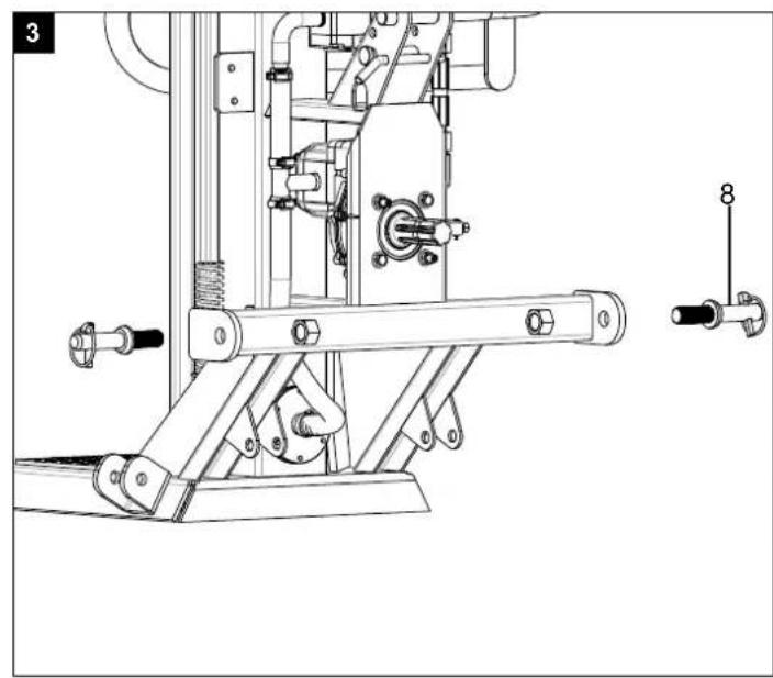
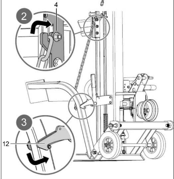
9.1 Fitting the three-point bolts (8) (fig. 3)
- Insert the three-point threaded bolts (8) through the holes provided and fix each one from the other side with an M22 nut.
9.2 Fitting the cardan shaft protective cover (7) (fig. 4)
- Place the cardan shaft protective cover (7) on the protruding grub screws on the cardan shaft and secure it with the two M10 collar nuts (7a).
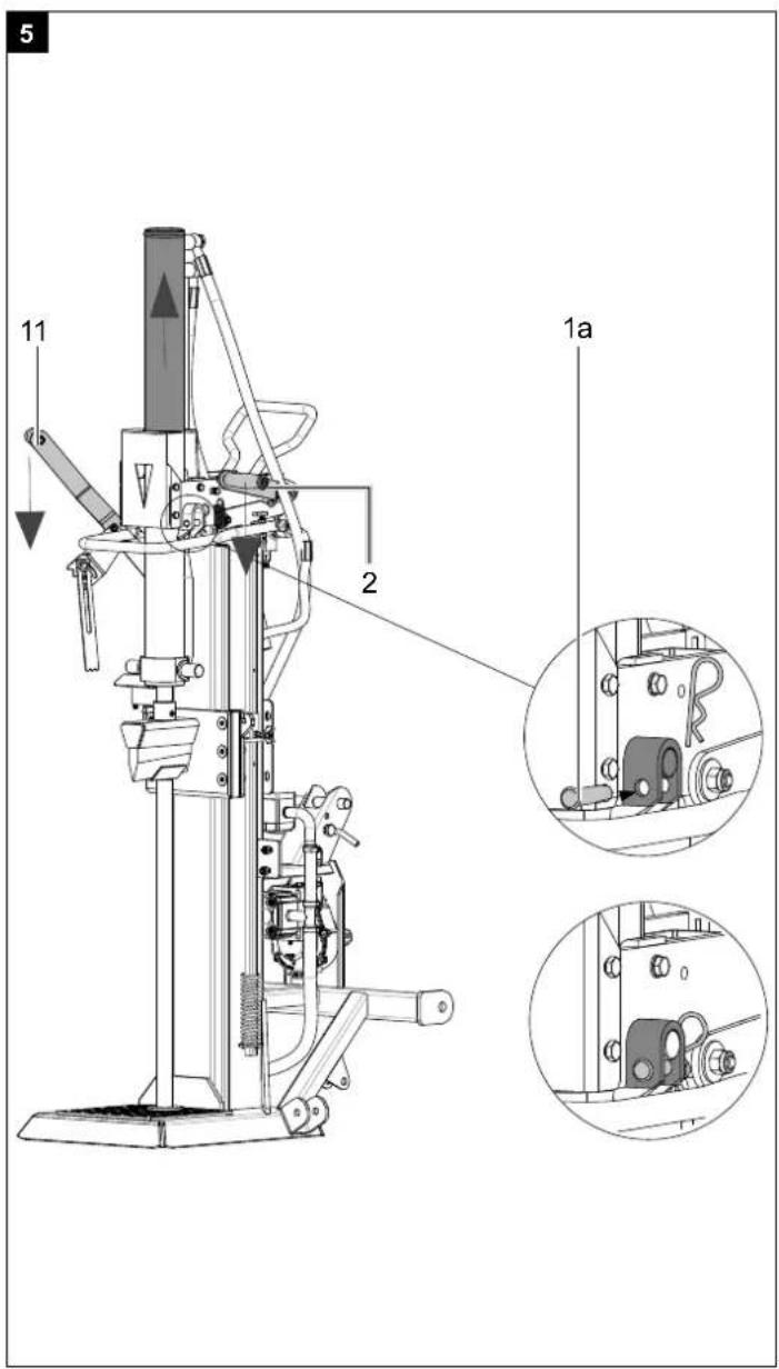
9.3 Bringing the splitter into working position (fig. 5 + 6)
- Lower the two operating levers (2 + 11) until the cylinder latches into the guide.
- Insert the two locking pins with split pin (1a) to secure the cylinder.
- Move the splitting knife (4) to the top position by pressing the return bar (3) downwards and remove the support (4a). Keep the prop (4a) in a good place as it will be needed for transporting the product.
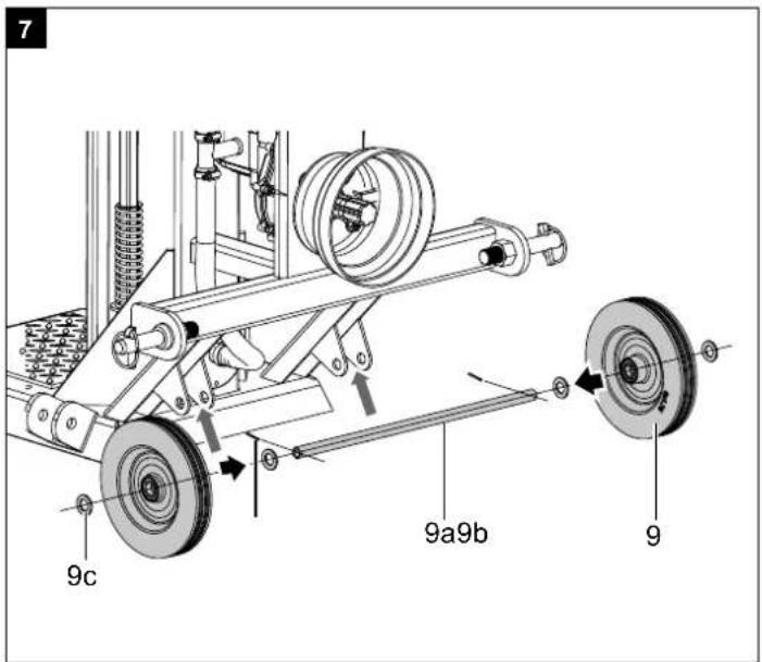
9.4 Fiting the wheel axle (9a) and transport wheels (9) (fig. 7)
- Push the wheel axle (9a) through the holes in the axle mount and centre it.
- Place the transport wheels (9) on the wheel axle (9a) and secure them with the locking pins (9b) and washers (9c) (see fig. 7).
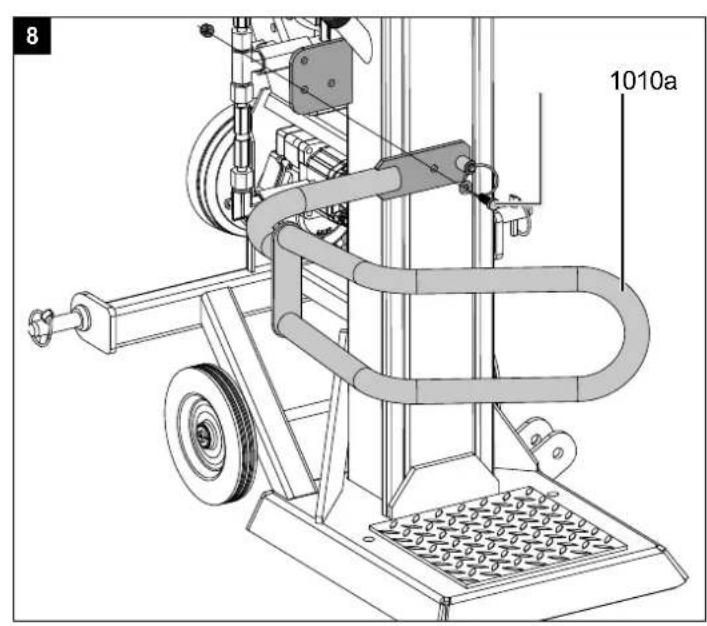
9.5 Fitting the retainer arm (10) (fig. 8)
- Secure the retaining arm (10) with an M10 x 35 mm hex screw, a washer and a hex nut (10a).
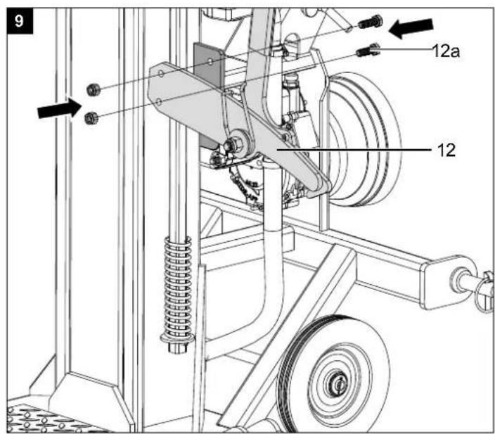
9.6 Fitting the retainer hook (12) (fig. 9)
- Attach the retaining hook (12) to the frame using two hex bolts and two collar nuts (12a). Note: Only tighten the connection once 9.7 has been completed.
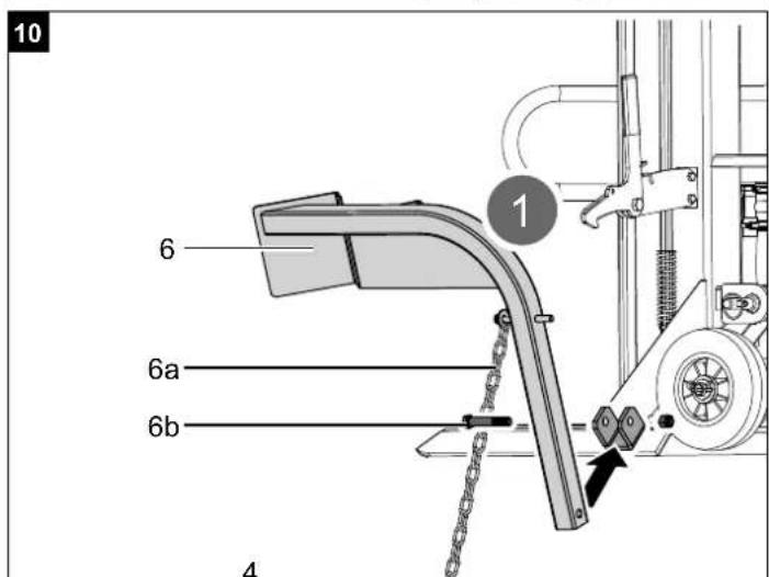
9.7 Fitting the trunk lifter (6) (fig. 10)
- Fasten the trunk lifter (6) to the retaining bracket using an M16 x 90 mm hex bolt and an M16 hex nut (6b).
- Hook the last link of the chain (6a) onto the guide of the splitting blade (4).
- Press the retaining hook lever (12) so that the pin on the trunk lifter (6) can latch into the retaining hook (12).
- Release the retainer hook lever (12) again.
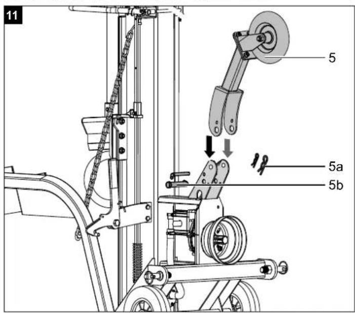
9.8 Fitting an additional transport wheel (5) (fig. 11)
-
Attach the additional transport wheel (5) as shown in fig. 11.
-
Secure the additional transport wheel (5) in the upper hole with the locking bolt and the locking pin (5b) as well as with the spring split pins (5a) when working with the splitter.
- Fix the additional transport wheel (5) in the lower hole during transport.
10. Start-up
ATTENTION!
Always make sure the product is fully assembled before commissioning!
Make sure that the product is installed completely and properly. Before each use, always check:
• The product for possible damage,
- whether all screws are tightened,
• the hydraulic oil for leaks and
- the oil level
• Function of the two-hand control (see function test)
- the safety devices.
10.1 Oil level check
The hydraulic system is a closed system with an oil tank, oil pump and control valve. Check the oil level regularly before commissioning. An oil level that is too low can damage the oil pump. The oil level must be within the middle mark on the oil dipstick. The splitting column must be retracted before the check, the product must be level. Screw in the oil dipstick fully, to measure the oil level.
10.2 Functional check (fig. 1)
Carry out a functional check before each use.
| Action: Result: | |
| Push both operating levers (2 + 11) down. | Splitting blade (4) goes down - until approx. 20 cm above the table. |
| Release one operating lever (2 or 11) at a time. | The splitting blade (4) remains in the selected position. |
| Release both operating levers (2 + 11). | The splitting blade (4) remains in the selected position. |
| Press the return bar (3) downwards. | Splitting blade (4) moves upwards. |
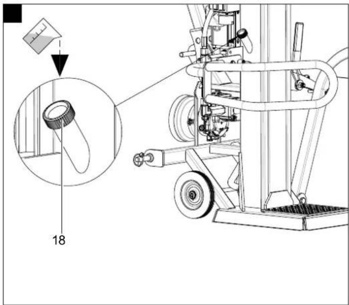
Attention!
Loosen the filler plug (18) before commissioning. Never forget to loosen the filler plug (18)! Otherwise, the air in the system will be repeatedly compressed and depressurised, which will destroy the seals of the hydraulic circuit and the log splitter will no longer be usable. In this case, the seller and the manufacturer disassociate themselves from any warranty claims.
10.3 Cardan shaft
- Before connecting the product to the power take-off shaft of the drive vehicle, ensure that the weight of the machine is suitable for the drive vehicle. The weight of the machine can be found on the manufacturer's rating plate.
- The cardan shaft may only be connected when the drive vehicle's engine is switched off.
- Only use approved cardan shafts that are suitable for use with the product. The cardan shaft must also be equipped with all safety devices, which must be in good condition.
- Do not stand near the cardan shaft when it is in operation.
- Ensure that the speed on the drive vehicle does not exceed the number specified on the rating plate.
- Before carrying out maintenance work or if the splitting blade (4) has jammed, first disconnect the product from the drive vehicle and switch off the engine.
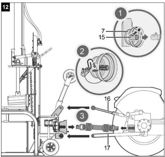
10.4 Attaching the splitter to the drive vehicle (fig. 12 + 13)
- Reverse the drive vehicle up to the product. Position the lower mounting arms close enough to the mounting pins of the metre log splitter.
- Apply the parking brake of the drive vehicle and switch off the engine. Block the rear wheels on both sides with wedges or other suitable objects.
- Remove the dust cover (15) and attach it to the cardan shaft protective cover (7).
- Lower the lower mounting arms (17) to the mounting pins of the product and secure them with the locking pins (17a).
- Position the upper mounting arm (16) in the bracket and align it with the holes in the bracket. Insert the hanger pin (16a) to lock the upper mounting arm.
- The cardan shaft end of the gearbox has a diameter of 34.8 mm and a connection with 6 teeth (standard category 1 cardan).
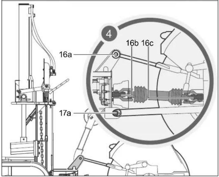
- Slide the cardan drive shaft over the power take-off shaft (16b) on the gearbox and on the drive vehicle (16c). Press in the spring pins located at both ends of the cardan shaft drive. Push the drive shaft further over the power take-off shaft (16b + 16c) until the spring pins spring out and engage in the teeth of the end of the cardan shaft.
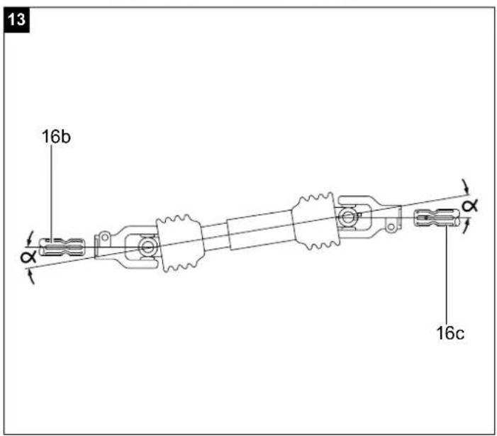
- Viewed from above and from the side of the shaft, the power take-off shaft on the metre log splitter (16b) and the power take-off shaft on the drive vehicle (16c) must be aligned parallel. The angles of the universal joints ( ) must be as small as possible.
- Secure the safety chain of the cardan shaft drive to a fixed part of the product and the drive to prevent the protective device from turning.
Check the direction of rotation of the PTO shaft (16c) of the drive vehicle. If the splitting blade (4) is not in the upper position, move it upwards by pressing the return bar (3). If the splitting blade (4) is already in the top position, activate the splitting mechanism by moving the two operating levers (2 + 11) downwards. This moves the splitting blade (4) downwards. If the splitting blade (4) does not move despite actuating the operating levers (2 + 11) or the return bar (3), stop the power take-off shaft drive and change its direction of rotation.
Never allow the power take-off shaft drive to run with the wrong direction of rotation! This will inevitably lead to the destruction of the pump system and no warranty claim can be made for this.
Only use cardan shafts with a CE mark, declaration of conformity and operating instructions! Read these instructions carefully before use! Carry out the aforementioned operations only with the engine switched off, the PTO connector disconnected and the ignition key removed!
10.5 Disconnecting the splitter from the drive vehicle (fig. 12 + 13)
- Apply the parking brake of the drive vehicle and switch off the engine. Block the rear wheels on both sides with wedges or other suitable objects.
- Remove the connecting pins (17a) and the hanger pin (16a).
- Remove the upper and lower mounting arm (16 + 17) from the mounts on the product.
- Pull out the spring pins at both ends of the drive shaft.
- Remove the drive shaft from the PTO shaft (16b + 16c).
- Fit the dust guard (15) back onto the power take-off shaft (16b).
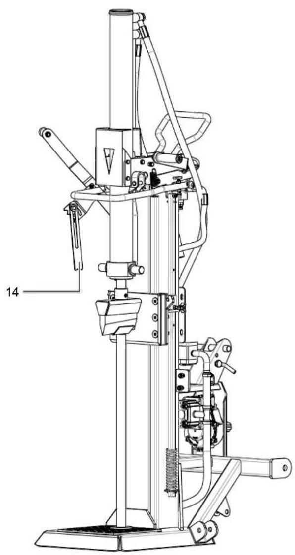
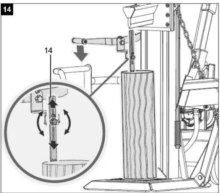
10.6 Using the claw (14) (fig. 14)
The height of the claw (14) can be set with the clamping screw at various stages to suit the length of the wood.
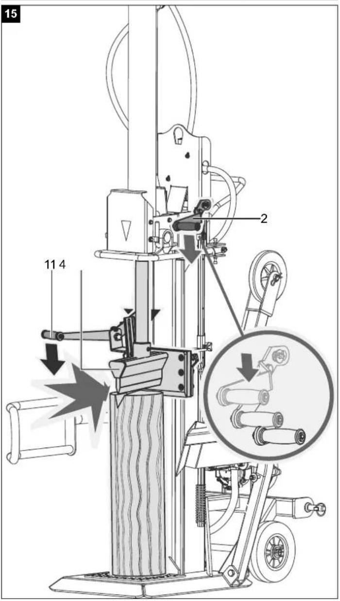
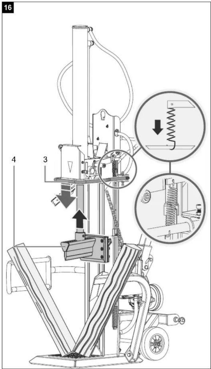
10.7 Splitting (fig. 15 + 16)
- If the outside temperature is below 5^ , allow the product to idle for approx. five minutes so that the hydraulic system reaches operating temperature.
Attention: The splitting blade (4) is very sharp. Danger of injury!
- When you press both operating levers (2 + 11) down, the splitting blade (4) moves downwards and splits the wood.
- Only split logs that have been sawn off straight.
- Split wood vertically.
- Never split horizontally or across the grain!
-
Wear suitable gloves and safety shoes when splitting wood.
-
If the wood is extremely overgrown, split the trunks from the outline.
Attention: Certain types of wood can come under a lot of tension during splitting and crack abruptly. - Knock out jammed wood against the splitting direction.
10.8 Operation of the trunk lifter (6) (fig. 10)
General information about the trunk lifter (6)
- The chain (6a) of the trunk lifter (6) may only be attached to the splitting blade using the last link for safety reasons.
- Ensure that no other people are present in the working range of the trunk lifter (6).
10.9 Operation of the trunk lifter (6) (fig. 10)
- Release the retaining hook of the trunk lifter so that the lifting tube can run freely.
- Move the splitting blade down until the lifting tube of the trunk lifter lies completely on the floor.
- In this position, you can roll the trunk to the split onto the lifting tube.
- The trunk must lie in the area between the two fixing points.
- Push the return bar (3) down and let the splitting blade (4) move up.
- Caution! Do not stand in the working range of the trunk lifter (6)! Danger of injury!
- Now align the trunk, press it against the claw (14) and split it. (Refer to: Working instructions)
- Then remove the split wood and move the splitting blade (4) and thus the trunk lifter (6) down again.
- A new log can now be rolled onto the trunk lifter (6).
10.10 Resetting the trunk lifter (6) (fig. 10)
This is used as a second guard arm when not using the trunk lifter (6). To do this, the trunk lifter (6) is raised until it engages on the retaining hook (12).
10.11 Trunk lifter (6) transport position (fig. 10)
Guide the trunk lifter (6) up by hand until it latches into place in the retainer hook (12).
Observe these instructions to ensure that you can work quickly and safely.
11. Cleaning
Only carry out modifications, adjustments and cleaning work when disconnected from the drive shaft.
We recommend that you clean the product directly after every use.
Wipe chippings and dust off the product from time to time with a cloth.
Clean the product at regular intervals using a damp cloth and a little soft soap. Do not use any cleaning products or solvents; they could attack the plastic parts of the product. Make sure that no water can penetrate the interior of the product.
12. Transport
The product can be easily transported using the 3-point attachment on the drive vehicle.
Before transporting the product, place it in the transport position.
To do this, move the splitting blade (4) downwards until it rests on the support (4a). Then remove both safety pins and their split pins (1a) and move the hydraulic cylinder down into the transport position by pressing the return bar (3) downwards.
Make sure there is sufficient manoeuvring space when driving, e.g. when turning, parking and at junctions.
Before transport, ensure that the product is properly and securely attached to the drive vehicle and that the cardan shaft has been disassembled.
Never transport the product with the cardan shaft drive connected.
Make sure that the product is raised high enough to pass obstacles during transport.
13. Storage
Store the product and its accessories in a dark, dry and frost-free place that is inaccessible to children. The optimum storage temperature lies between 5 and 30 °C.
Store the tool in its original packaging.
Cover the product to protect it from dust or moisture.
Store the operating manual with the product.
14. Maintenance
Attention!
Ensure that the cardan shaft is not connected to the drive vehicle.
Oil change intervals
Initial oil change after 50 operating hours, then every 250 operating hours.
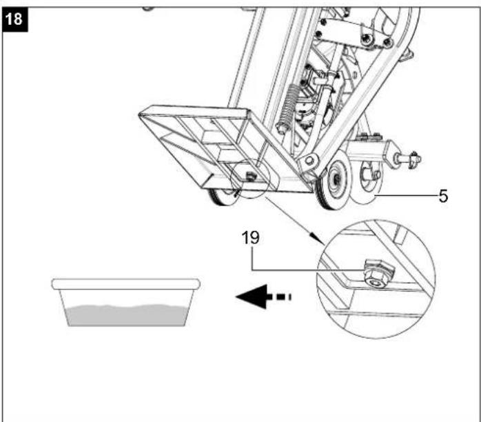
14.1 Changing oil (fig. 17 + 18)
Due to the heavy weight of the product, we recommend that maintenance work is carried out by at least two people.
- Move the additional transport wheel (5) to the transport position.
- Use the transport wheels (9) to tilt the product so that you can easily reach the oil drain plug (19).
-
Place an appropriately sized container under the oil drain screw (19).
-
Open the oil filling opening (18).
- Open the oil drain screw (19) and carefully allow the oil to run into the container.
- Reinsert the oil drain screw (19) with seal and tighten securely.
- Top up with new hydraulic oil. (contents: see technical data) and check the oil level with the oil dipstick. After an oil change, actuate the splitting blade (4) several times without actually splitting.
Attention! Do not allow any dirt particles to enter the oil container.
Dispose of the used oil properly at a local used oil collection point. Dumping used oil in the soil or mixing it with waste is prohibited.
We recommend oil from the HLP 32 range.
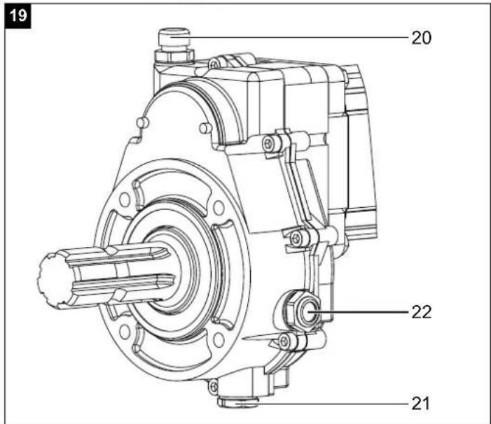
14.2 Changing the gearbox oil (fig. 19)
The gearbox is filled with SAE90 gear oil at the factory.
Drain the gear oil after the first 50 operating hours and replace it with new oil as specified. The next oil change should then be carried out every 250 operating hours or every six months, whichever comes first.
- Disassemble the cardan shaft protective cover (7) and set a sufficiently large container under the gearbox.
- First open the oil drain screw (gearbox) (21) and then the oil filler plug (20) and drain the oil completely.
- Close the oil drain screw (gearbox) (19) with a new seal and fill new SAE90 gear oil into the opening of the oil filler plug (20) using a funnel until the lower edge of the oil sight glass (22) is almost covered with oil.
Check the oil level every 8 working hours. The oil level is correct when the lower edge of the oil sight glass (22) is almost covered with oil.
Hydraulic system
The hydraulic system is a closed system with an oil tank, oil pump and control valve.
The factory-completed system must not be changed or tampered with.
Check the oil level regularly.
If the oil level is too low, the oil pump will be damaged. Check hydraulic connections and screw connections regularly for leaks - retighten if necessary.
Please provide the following information in the event of any enquiries:
• Machine data - type plate
Service information
With this product, it is necessary to note that the following parts are subject to natural or usage-related wear, or that the following parts are required as consumables.
Wearing parts*: Riving knife / riving spar guides, hydraulic oil, gear oil
* may not be included in the scope of delivery!
Spare parts and accessories can be obtained from our service centre. To do this, scan the QR code on the cover page.
15. Disposal and recycling
Notes for packaging


The packaging materials are recyclable. Please dispose of packaging in an environmentally friendly manner.
You can find out how to dispose of the disused device from your local authority or city administration.
Fuels and oils
- Before disposing of the product, the fuel tank and the motor oil tank must be emptied!
- Fuel and engine oil do not belong in household waste or drains, but must be collected or disposed of separately!
- Empty oil and fuel tanks must be disposed of in an environmentally friendly manner.
16. Troubleshooting
The following table shows fault symptoms and describes remedial measures in the event of your machine failing to work properly. If you cannot localise and rectify the problem with this, please contact your service workshop.
Important note in the case of repairs: When returning the product for repair, for safety reasons, ensure that it is free of oil and fuel when it is sent to the service centre.
| Fault Possible cause Remedy | ||
| The blade does not move downwards or reach its splitting force | Drive shaft speed incorrect Check drive shaft speed | |
| Drive shaft rotating in wrong direction | Check and adjust the direction of rotation | |
| Low oil level Check the oil level and top up | ||
| One of the levers is not connected Check the attachment of the lever | ||
| Dirt in the rails Clean the rails | ||
Günzburger Straße 69
D-89335 Ichenhausen
Cher client,
Scheppach GmbH, Günzburger Str. 69, 89335 Ichenhausen
| DE | EU-KonformitätserklärungÜbersetzung der OriginalkonformitätserklärungWir erklären in alleiniger Verantwortung, dass das hier beschriebene Produkt mit den geltenden Richtlinien und Normen übereinstimmt. | Der hier beschriebene Gegenstand der Erklärung erfüllt die Vorschriften der Richtlinie 2011/65/EU des Europäischen Parlaments und des Rates vom 8. Juni 2011 zur Beschränkung der Verwendung bestimmter gefährlicher Stoffe in Elektro- und Elektronikgeräten.*Technische Unterlagen verfügbar bei: ** | ||
| Artikelnummer*** | Artikelbezeichnung: Meterholzspalter FBCC12TPDF | Marke**** | ||
| GB | EU Declaration of ConformityTranslation of the original Declaration of ConformityWe declare under our sole responsibility that the product described here complies with the applicable directives and standards. | The object of the declaration described here fulfils the regulations of the directive 2011/65/EU of the European Parliament and Council from 8th June 2011, on the restriction of the use of certain hazardous substances in electrical and electronic equipment.*Technical documentation available at: ** | ||
| Item number*** | Item designation: Metre log splitter FBCC12TPDF | Brand**** | ||
| FR | Déclaration UE de conformitéTraduction de la déclaration de conformité originaleNous déclarons, sous notre propre responsabilité, que le produit décrit ici est conforme aux directives et normes en vigueur. | L'appareil décrit ci-dessus dans la déclaration est conforme aux réglementations de la directive 2011/65/EU du Parlement Européen et du Conseil du 8 juin 2011 visant à limiter l'utilisation de substances dangereuses dans la fabrication des appareils électriques et électroniques.*Dossier technique auprès de: ** | ||
| Référence*** | Désignation de l'article: Fendeur de bûches d'un mètre FBCC12TPDF | Marque**** | ||
| ***39054219953 | ****SCHEPPACH | |||
| ** :Andreas PecherGünzburger Str. 69D-89335 Ichenhauseni.V.Andreas Pecher /Head of Project ManagementI.V.Simon Schunk /Division Manager Product CenterIchenhausen, 23.07.2025 | ☒ 2011/65/EU*☐ 2014/30/EU☐ 2016/1628/EU☐ 2014/29/EU☐ 2014/35/EU☐ 2004/22/EG☐ 2014/68/EU☐ 89/686/EWG_96/58/EG☐ 90/396/EWG | ☒ 2006/42/EG☐ Annex IVNotified Body:Notified Body No.:Certificate No.: | ☐ 2000/14/EG; 2005/88/EGNoise:measured L_WA = dBguaranteed L_WA = dB☐ Annex V☐ Annex VINotified Body:Notified Body No.: |
| ☐ 2016/1628/EU | Emission No.: | ||
| EN 609-1:2017 | |||
Garantie DE
Apparent defects must be notified within 8 days from the receipt of the goods. Otherwise, the buyer's rights of claim due to such defects are invalidated. We guarantee for our machines in case of proper treatment for the time of the statutory warranty period from delivery in such a way that we replace any machine part free of charge which provably becomes unusable due to faulty material
or defects of fabrication within such period of time. With respect to parts not manufactured by us we only warrant insofar as we are entitled to warranty claims against the upstream suppliers. The costs for the installation of the new parts shall be borne by the buyer. The cancellation of sale or the reduction of purchase price as well as any other claims for damages shall be excluded.