
FBCC25T - Log splitter SCHEPPACH - Free user manual and instructions
Find the device manual for free FBCC25T SCHEPPACH in PDF.

| Product type | Vertical log splitter |
| Brand | Scheppach |
| Model | FBCC25T |
| Dimensions (L x W x H) | 1540 x 1140 x 2520 mm |
| Weight | 319 kg |
| Power supply | 400 V / 50 Hz three-phase |
| Power consumption (P1) | 5100 W |
| Power output (P2) | 4000 W |
| Max. splitting force | 25 t |
| Admissible log length | 560 - 1100 mm |
| Admissible log diameter | 80 - 350 mm |
| Cylinder stroke | 948 mm |
| Descent speed | 10.5 cm/s |
| Return speed | 7.5 cm/s |
| Hydraulic oil tank capacity | 24 L |
| Recommended hydraulic oil | HLP 32 |
| Oil change maintenance | First oil change at 50 h, then every 250 h |
| Drive | Power take-off (540 min⁻¹) + electric motor |
| Safety | Two-hand control, thermal protection, emergency stop |
| Usage | Vertical only, one person |
Frequently Asked Questions - FBCC25T SCHEPPACH
User questions about FBCC25T SCHEPPACH
0 question about this device. Answer the ones you know or ask your own.
Ask a new question about this device
Download the instructions for your Log splitter in PDF format for free! Find your manual FBCC25T - SCHEPPACH and take your electronic device back in hand. On this page are published all the documents necessary for the use of your device. FBCC25T by SCHEPPACH.
USER MANUAL FBCC25T SCHEPPACH
natural_image
Industrial machine with vertical cylindrical component and attached mechanical arms (no visible text or symbols)FBCC25T
| DE | HolzspalterOriginalbedienungsanleitung | 8 |
| GB | Log splitterTranslation of original instruction manual | 20 |
| FR | Fendeur de bûchesTraduction des instructions d'origine | 30 |
1
2
natural_image
Technical line drawing of a mechanical lifting device with no visible text or symbols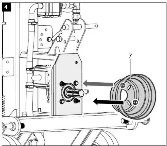
natural_image
Mechanical assembly diagram showing a clamping mechanism with no visible text or symbols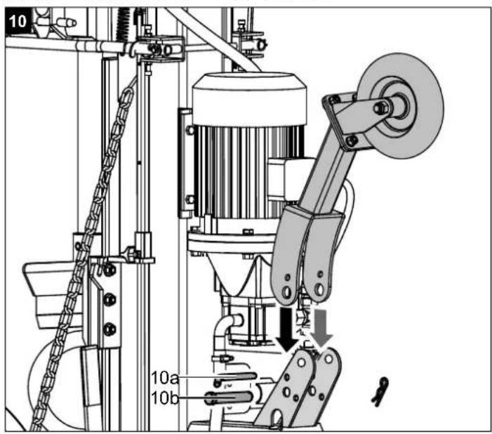
natural_image
Technical line drawing of a circular electrical component with mounting holes and central slots (no text or symbols)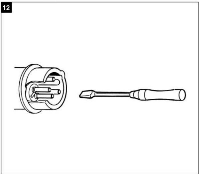
natural_image
Technical line drawing of a screwdriver and its internal component (no text or symbols)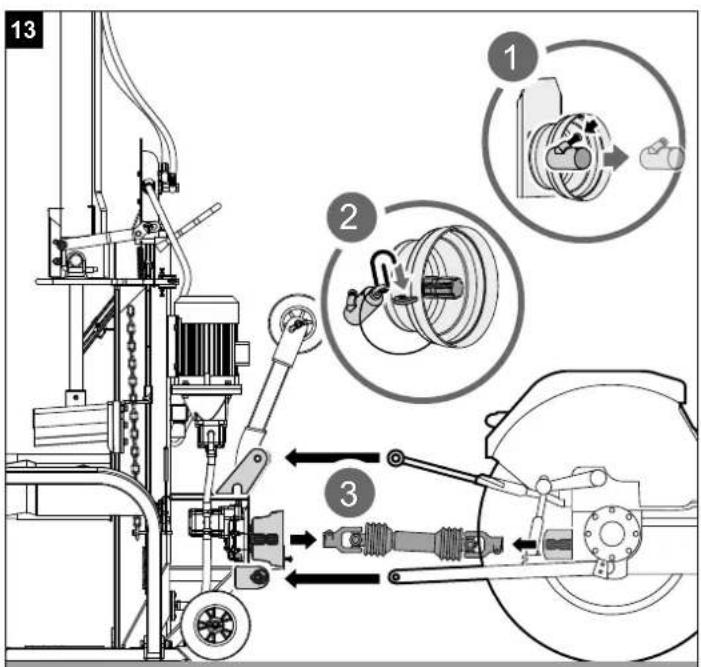
natural_image
Technical line drawing of a mechanical assembly with an inset showing a close-up of a mechanical component (no text or symbols present)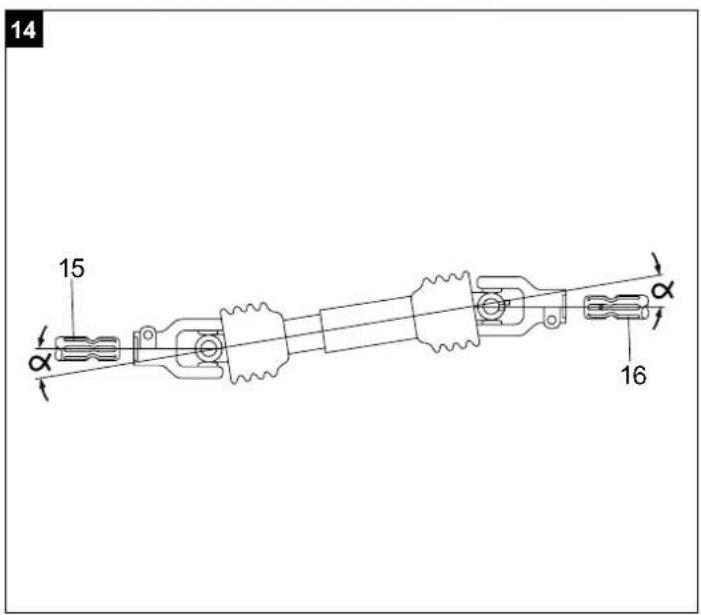
17
The image is too blurry to recognize any text content.
natural_image
Technical line drawing of a mechanical assembly with pipes and a central valve (no text or symbols)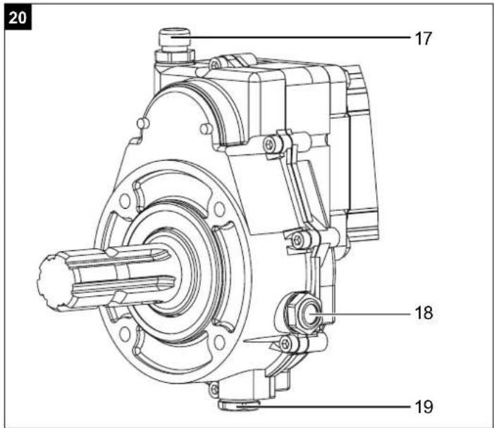
Günzburger Straße 69
D-89335 Ichenhausen
Verehrter Kunde
Explanation of the symbols on the equipment
The use of symbols in this manual is intended to draw your attention to possible risks. The safety symbols and the explanations that accompany them must be perfectly understood. The warnings in themselves do not remove the risks and cannot replace correct actions for preventing accidents.
 | Please read the manual before start-up |  | Caution! Switch off the engine before repair, maintenance and cleaning. Unplug the mains plug. |
 | Wear safety footwear | 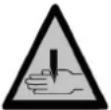 | Danger of bruising and injury from sharp edges; never touch danger areas when the cleaver is moving. |
 | Wear work gloves High-voltage, danger to li |  | |
 | Wear safety goggles. Sparks created during work or fragments, chippings and dust ejected by the device can case sight loss. |  | The machine must only be operated by one person! |
 | No smoking in the working area Caution! M |  | Part 1 |
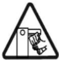
 | Do not spill hydraulic oil on the floor |  | Do not transport the device in the horizontal position! |
 | Keep your workspace clean! Unti-diness can cause accidents! |  | Authorised personnel only |
 | Dispose of waste oil correctly (waste oil collection point on site). Do not dump waste oil in the ground or mix it with waste. | 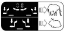 | Two work speeds:1. Low speed and full splitting power2. High speed and reduced splitting power |
 | Do not remove jammed trunks with your hands. |  | Loosen the vent bolt two revolu-tions, before starting work. Close before transport. |
 | Do not remove or modify protec-tion and safety devices. |  | Lifting point |
| Caution! | In this operating manual, we have used this sign to mark all sections that concern your safety. | CE | The product complies with the applicable European directives. |
Table of contents: Page:
- Introduction......22
- Device description....22
- Scope of delivery 22
- Intended use....22
- Safety notes ...... 23
- Additional safety instructions.... 23
- Technical data 24
- Unpacking 24
- Attachment / Before starting the equipment....24
- Initial operation....25
- Electrical connection 27
- Cleaning 27
- Transport 27
- Storage....27
- Maintenance....27
- Disposal and recycling 28
- Troubleshooting 29
- Declaration of conformity 43
1. Introduction
Manufacturer:
Scheppach GmbH
Günzburger Straße 69
D-89335 Ichenhausen
Dear Customer,
We hope your new tool brings you much enjoyment and success.
Note:
According to the applicable product liability laws, the manufacturer of the device does not assume liability for damages to the product or damages caused by the product that occurs due to:
- Improper handling,
• Non-compliance of the operating instructions, - Repairs by third parties, not by authorized service technicians,
- Installation and replacement of non-original spare parts,
• Application other than specified, - A breakdown of the electrical system that occurs due to the non-compliance of the electric regulations and VDE regulations 0100, DIN 57113 / VDE0113.
We recommend:
Read through the complete text in the operating instructions before installing and commissioning the device. The operating instructions are intended to help the user to become familiar with the machine and take advantage of its application possibilities in accordance with the recommendations. The operating instructions contain important information on how to operate the machine safely, professionally and economically, how to avoid danger, costly repairs, reduce downtimes and how to increase reliability and service life of the machine.
In addition to the safety regulations in the operating instructions, you have to meet the applicable regulations that apply for the operation of the machine in your country. Keep the operating instructions package with the machine at all times and store it in a plastic cover to protect it from dirt and moisture. Read the instruction manual each time before operating the machine and carefully follow its information. The machine can only be operated by persons who were instructed concerning the operation of the machine and who are informed about the associated dangers. The minimum age requirement must be complied with.
In addition to the safety instructions in this operating manual and the separate regulations of your country, the generally recognised technical rules for operating woodworking machines must also be observed.
We accept no liability for accidents or damage that occur due to a failure to observe this manual and the safety instructions.
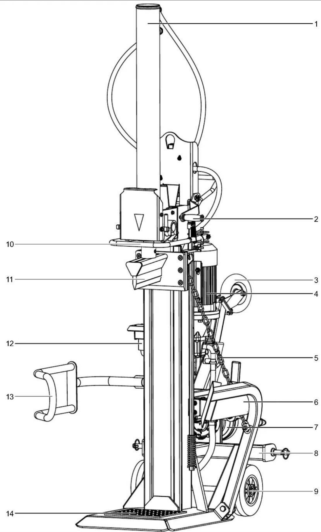
2. Device description
- Cylinder
- Operating handle
- Additional transport wheel
- Motor
- Chain
- Log lifter
- Drive shaft protective cap
- Three-point linkage
- Transport wheels
- Return bracket
- Splitting wedge
- Combination switch/plug
- Supporting arm
- Work table
- Oil filler opening
- Oil level window
-
Oil drain plug
-
Drive shaft end on the kindling splitter
-
Drive shaft end on the kindling tractor
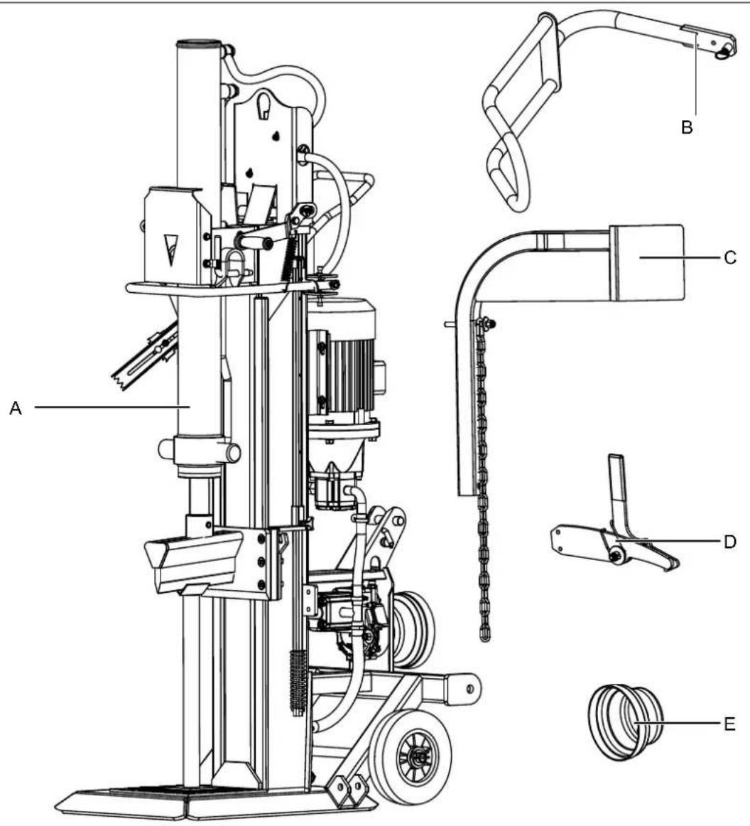
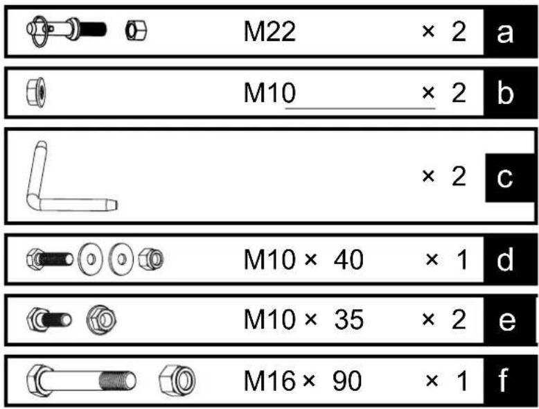
3. Scope of delivery
A. Splitter
B. Supporting arm
C. Log lifter
D. Hook
E. Drive shaft protective cap
F. Enclosed accessories bag (a, b, c, d, e, f)
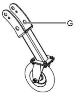
G. Additional transport wheel
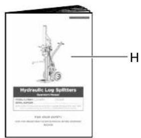
H. Operating manual
4. Intended use
The equipment is to be used only for its prescribed purpose. Any other use is deemed to be a case of misuse. The user / operator and not the manufacturer will be liable for any damage or injuries of any kind caused as a result of this.
To use the equipment properly you must also observe the safety information, the assembly instructions and the operating instructions to be found in this manual.
All persons who use and service the equipment have to be acquainted with this manual and must be informed about the equipment's potential hazards.
It is also imperative to observe the accident prevention regulations in force in your area. The same applies for the general rules of health and safety at work.
The manufacturer will not be liable for any changes made to the equipment nor for any damage resulting from such changes.
- The hydraulic log splitter can only be used in a vertical position. Logs may only be split along the direction of the fiber.
- Never split logs in horizontal position or against the direction of the fiber.
- The safety, work and maintenance instructions of the manufacturer as well as the dimensions indicated in the Technical Data section must be adhered to
- The applicable accident prevention regulations as well as all generally recognized safety rules must be adhered to.
- Only persons who have been trained in the use of the machine and have been informed of the various dangers may work with the machine and service or repair it. Arbitrary modifications of the machine release the manufacturer from any responsibility for resulting damage.
- The machine may only be used with original accessories and original tools of the manufacturer.
- Any other use exceeds authorization. The manufacturer is not responsible for any damages resulting from unauthorized use; risk is the sole responsibility of the operator.
Please note that our equipment has not been designed for use in commercial, trade or industrial applications. Our warranty will be voided if the equipment is used in commercial, trade or industrial businesses or for equivalent purposes.
5. Safety notes
WARNING: When you use electric machines, always observe the following safety instructions in order to reduce the risk of fire, electric shock, and injuries.
Please read all the instructions before you work with this machine.
- Observe all safety notes and warnings attached to the machine.
- See to it that safety instructions and warnings attached to the machine are always complete and perfectly legible.
- Protection and safety devices on the machine may not be removed or made useless.
- Protection and safety devices on the machine may not be removed or made useless.
- Check electrical connection leads. Do not use any faulty connection leads.
-
Before putting into operation check the correct function of the two-hand control.
-
Operating personnel must be at least 18 years of age. Trainees must be at least 16 years of age, but may only operate the machine under adult supervision.
- Wear working gloves when working.
- Caution when working: There is a danger to fingers and hands from the splitting tool.
- Use adequate supports when splitting heavy or bulky logs.
- Before starting any conversion, setting, cleaning, maintenance or repair work, always switch off the machine and disconnect the plug from the power supply.
- Connections, repairs, or servicing work on the electrical equipment may only be carried out by an electrician.
- All protection and safety devices must be replaced after completing repair and maintenance procedures.
- When leaving the work place, switch off the machine and disconnect the plug from the power supply.
6. Additional safety instructions
- The log splitter may only be operated by one person.
- Wear protective gear like safety goggles or other eye protection, gloves, safety shoes etc. to protect yourself from possible injuries.
- Never split logs containing nails, wire, or other foreign objects.
- Already split wood and wood chips can be dangerous. You can stumble, slip or fall down. Keep the working area tidy.
- While the machine is switched on, never put your hands on moving parts of the machine.
- Only split logs with a maximum length of 110 cm.
Warning! This electric tool generates an electromagnetic field during operation. This field can impair active or passive medical implants under certain conditions. In order to prevent the risk of serious or deadly injuries, we recommend that persons with medical implants consult with their physician and the manufacturer of the medical implant prior to operating the electric tool.
Remaining hazards
The machine has been built using modern technology in accordance with recognized safety rules. Some remaining hazards, however, may still exist.
- The splitting tool can cause injuries to fingers and hands if the wood is incorrectly guided or supported.
-
Thrown pieces can lead to injury if the work piece is not correctly placed or held.
-
Injury through electric current if incorrect electric connection leads are used.
- Even when all safety measures are taken, some remaining hazards which are not yet evident may still be present.
- Remaining hazards can be minimized by following the safety instructions as well as the instructions in the chapter Authorized use and in the entire operating manual.
- Health hazard due to electrical power, with the use of improper electrical connection cables.
- Release the handle button and switch off the machine prior to any operations.
- Avoid accidental starts of the machine: Do not press the start button while inserting the plug into the socket.
- Use the tools recommended in this manual to obtain the best results from your machine.
• Always keep hands away from the work area when the machine is running.
7. Technical data
Drive Drive shaft + e-motor
| Motor V/Hz | 400V / 50Hz |
| Input P1 W | 5100 |
| Output P2 W | 4000 |
| Operating mode | S6 40% |
| PTO shaft / Motor speed | 540 |
| 1/min | 1400 |
| Phase inverter | yes |
| Dimensions D/W/H | 1540 x 1140 x 2520 mm |
| Wood length min. - max. | 560 - 1100 mm |
| Wood diameter min. - max. | 80 - 350 mm |
| Power max. tons* | 25 |
| Piston stroke | 948 mm |
| Forward speed cm/s | 10,5 |
| Return speed cm/s | 7,5 |
| Oil quantity l | 24 |
| Weight kg | 319 |
Subject to technical changes!
8. Unpacking
Open the packaging and remove the device carefully. Remove the packaging material as well as the packaging and transport bracing (if available).
Check that the delivery is complete.
Check the device and accessory parts for transport damage.
In case of complaints the dealer must be informed immediately. Subsequent complaints will not be accepted.
If possible, store the packaging until the warranty period has expired.
Read the operating manual to make yourself familiar with the device prior to using it.
Only use original parts for accessories as well as for wearing and spare parts. Spare parts are available from your specialized dealer.
Specify our part numbers as well as the type and year of construction of the device in your orders.
ATTENTION
The device and packaging materials are not toys! Children must not be allowed to play with plastic bags, film and small parts! There is a risk of swallowing and suffocation!
9. Attachment / Before starting the equipment
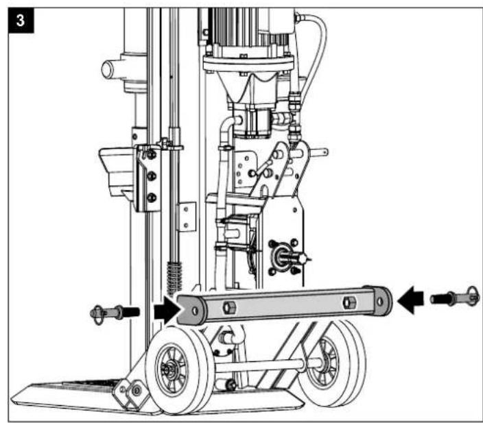
9.1 Attaching the three-point bolts (enclosed accessories bag A) (Fig. 3)
Insert the threaded bolts in the designated holes and fix them from the other side with an M22 nut each.
9.2 Attaching the drive shaft protective cap (7) (enclosed accessories bag B) (Fig. 4)
Place the drive shaft protective cap on the protruding threaded receivers at the drive shaft and secure it with both M10 nuts.
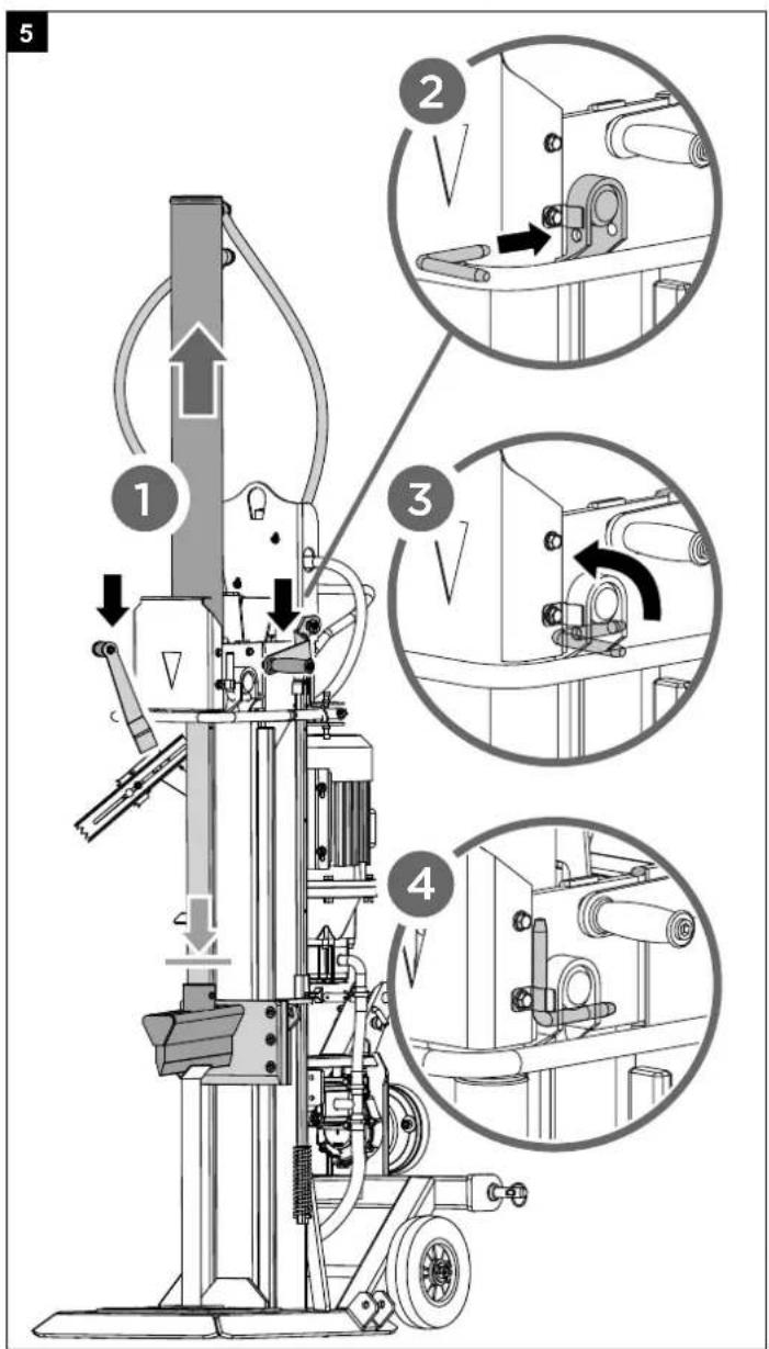
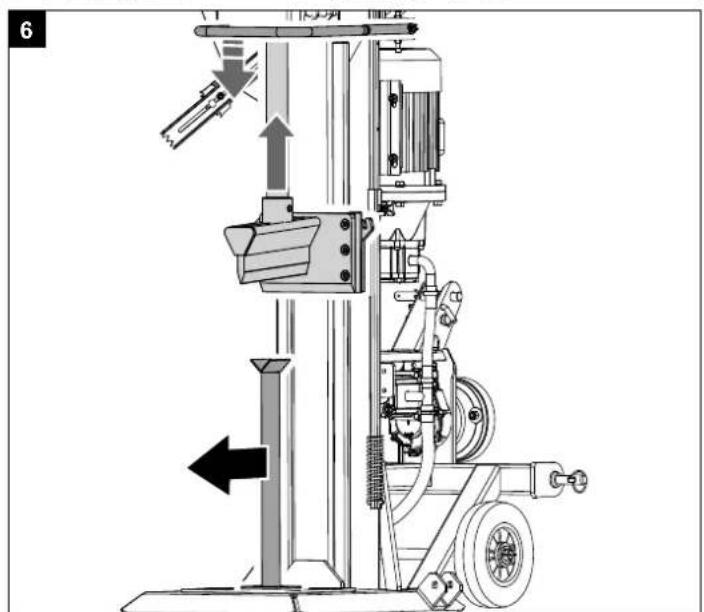
9.3 Putting the splitter into the work position (enclosed accessories bag C) (Fig. 5 + 6)
Connect the splitter to the mains power. Be aware of the motor's direction of rotation. Lower both control handles until the cylinder engages with the guide. Insert the two L-pins (C) to secure the cylinder on the kindling splitter. Secure the L-pins in the spring tabs. Then bring the splitting blade to the top position and remove the support. You must store the support safely because it is needed every time the splitter is transported.
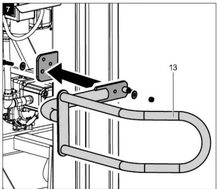
9.4 Attaching the supporting arm (13)
(enclosed accessories bag D) (Fig. 7)
Secure the supporting arm with a hexagon bolt M10x40, two washers and a nut.
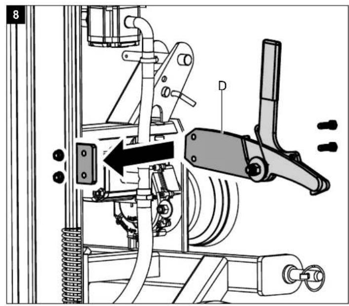
9.5 Attaching the hook (D)
(enclosed accessories bag E) (Fig. 8)
Attach the hook on the frame with 2 hexagon bolts and 2 nuts.
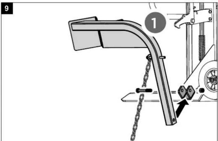
9.6 Attaching the log lifter
(enclosed accessories bag F) (Fig. 9)
Attach the log lifter on the fixing bracket with 1 hexagon bolt M16x100.
Hook the chain onto the splitting blade.
Attaching the additional wheel (Fig. 10)
Mount the transport wheel as shown in Fig. 10. Attach the wheel using a bolt (10b) and a spring pin. Fix the wheel in the upper hole with the locking pin (10a) when working with the splitter. Fix the wheel in the lower hole during transport.
▲ IMPORTANT!
You must fully assemble the appliance before using it for the first time!
10. Initial operation
Make sure the machine is completely and expertly assembled. Check before every use:
- The connection cables for any defective spots (cracks, cuts etc.).
• The machine for any possible damage.
• The firm seat of all bolts. - The hydraulic system for leakage.
- The oil level.
Checking the oil level (Fig. 13)
The hydraulic unit is a closed system with oil tank, oil pump and control valve. Check the oil level regularly before every use. Too low an oil level can damage the oil pump. The level of oil must be checked when the riving knife is pulled back. If the oil level is at the lower notch, then the oil level is at a minimum. Should this be the case, oil must be immediately added. The upper notch indicates the maximum oil level. The machine must be on level ground. Screw in the oil dipstick fully, to measure the oil level.
E-Motor
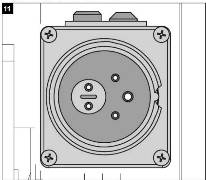
Check the running direction of the motor. If the splitting arm is not in the top position, bring the splitting blade in the top position, using the return bracket or handles. If the splitting arm is already in the top position, activate the splitting mechanism by moving both levers down. This will move the splitting arm down. If the splitting blade does not move despite activation of the handles or return bracket, immediately turn off the machine. Turn the pole reversing unit in the plug-in module (Fig. 11 + 12) to change the rotational direction of the motor.
Never let the motor run in the wrong direction! This will inevitably destroy the pump system and no warranty claim can be made.
Functional test
Test the function before every use.
Action:
Result:
| Push both handles towards below. | Splitting knife goes down to approx. 20 cm above the table. |
| Let one handle loose, then the other. | Splitting knife stops in the desired position. |
| Let both handles loose. | Splitting knife stops in the desired position. |
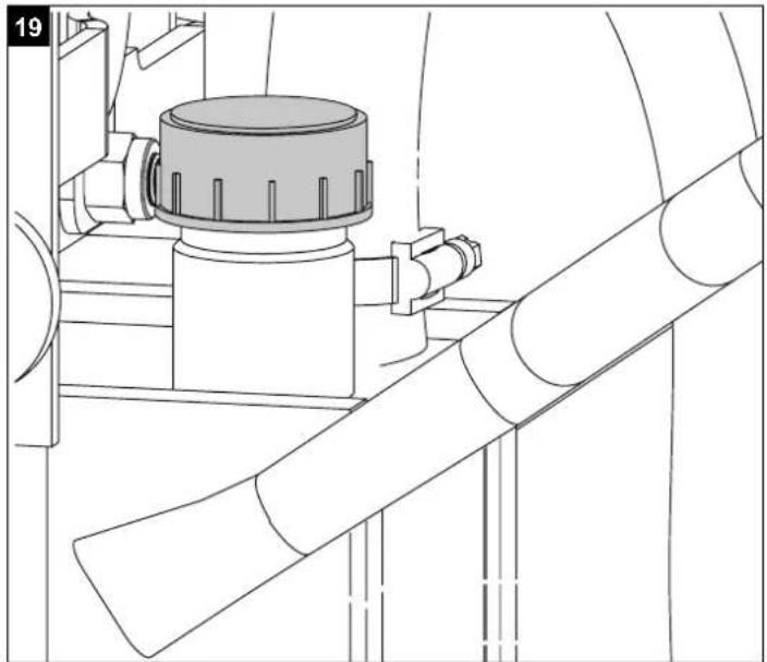
Warning!
Loosen the filling screw (Fig. 19) before commissioning.
Never forget to loosen the filling screw! Otherwise, the air in the system will constantly be compressed and decompressed with the result that the seals of the hydraulic circuit will be destroyed and the wood splitter can no longer be used. In this case, the seller and the manufacturer will not be liable to warranty services.
Switching on and off, (12)
Press the green button for switching on.
Press the red button for switching off.
Note: Check the function of the ON/OFF unit before every use by switching on and off once.
Restarting safety in case of current interruption (no-volt release).
In case of current failure, inadvertent pulling of the plug, or a defective fuse, the machine is switched off automatically.
For switching on again, press anew the green button of the switch unit.
Drive shaft
- That the guides on the splitting column are lubricated with grease.
- Before connecting the machine to the three-point linkage of the traction unit, ensure that the traction unit is suitable for the weight of the machine. The weight of the machine can be seen on the manufacturer's rating plate.
- After the traction unit's motor is turned off, connect the drive shaft.
- Exclusively use approved drive shafts and those that are suitable for use with the wood splitter. Furthermore, the drive shaft must be equipped with all safety devices which must be in a good condition.
- Don't stand close to the drive shaft when it is in operation.
- Ensure that the tractor unit's speed does not exceed the number on the rating plate, max. 540 per min.
- Before maintenance work or if the riving knife is jammed, first disconnect the machine from the tractor unit, after turning off the tractor unit.
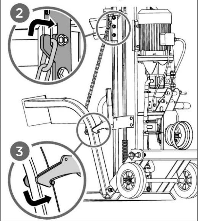
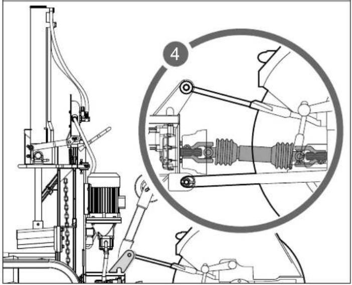
Attaching the splitter to the tractor unit,
Fig. 13 + 14
-
Reverse the tractor unit to the wood splitter. Position the lower support arms close enough to the kindling splitter's fixing pins.
-
Activate the tractor unit's parking brake and turn off the motor. Block the back wheels on both sides with wedges or other suitable objects.
-
Remove the dust cover (1) and attach it to the drive shaft protective cap (2).
-
Lower the bottom support arms onto the kindling splitter's fixing pins and secure them with the locking pins (3).
-
Position the top support arm in the bracket and align it with the bracket holes. Insert the hitch pin to lock the top support arm in place.
- The transmission drive shaft end has a diameter of 34.8 mm and a connection with 6 teeth (Standard Category 1 PTO).
-
Push the drive shaft over the drive shaft end on the transmission and tractor unit. Push down the spring pins located on both ends of the drive shaft. Push the drive shaft further over the drive shaft ends until the spring pins jump out and the teeth of the drive shaft end lock.
-
Aligning the drive shaft
Viewed from the top and the side of the shaft, the drive shaft end on the kindling splitter (15) and the drive shaft end on the tractor unit (16) have to be aligned in parallel. The angle of the drive shaft joints ( ) must be as small as possible.
- Secure the safety chain of the shaft drive on a fixed part of the kindling splitter and tractor unit to prevent the safety device turning.
Check the running direction of the tractor unit's drive shaft. If the splitting arm is not in the top position, bring the splitting blade in the top position, using the return bracket or handles. If the splitting arm is already in the top position, activate the splitting mechanism by moving both levers down. This will move the splitting arm down.
If the splitting blade does not move despite activation of the handles or return bracket, stop the shaft drive and change its direction.
Never let the shaft drive run in the wrong direction! This will inevitably destroy the pump system and no warranty claim can be made.
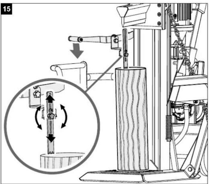
Using the safety arm (Fig. 15)
The safety arm can be set at different height positions, depending on the length of the wood.
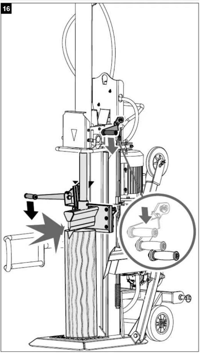
Splitting (Fig. 16 + 17)
- If the outside temperature is below 5°C, let the machine run idle for about 5 minutes so the hydraulic system reaches its operating temperature. Place the log under the splitting blade vertically.
Caution: The splitting blade is very sharp. Risk of injury!
- When you push both operating levers down, the splitting blade goes down and splits the wood.
- Only ever split logs that have been sawn off straight.
- Split the log vertically.
- Never split it lying down or diagonally to the grain!
- Wear suitable gloves and safety boots when splitting wood.
- Split very misshapen logs from the edge.
Caution: During splitting, some logs can be under significant tension and suddenly break.
- Force jammed logs out by applying pressure in the splitting direction or by raising the riving knife. In this case, only push the handles up, do not use the return bracket. Caution: Risk of injury
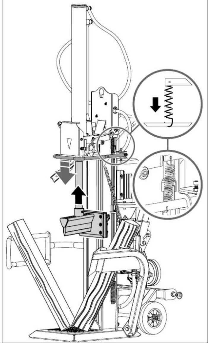
Operating the log lifter (6)
General information about the log lifter:
- For safety reasons, the log lifter chain may only be hung on the splitting blade with the last link.
- Ensure that nobody else is within the working environment of the log lifter.
Operating the log lifter:
- Loosen the log lifter restraining hook so the lifting tube can move freely.
- Move the splitting blade so far down that the log lifter lifting tube lies on the ground.
- In this position, you can roll the log to be split onto the lifting tube. (The log has to be between the two fixing tips.)
- Push the return bracket down or the handles up so the splitting blade moves up. (Caution! Do not stand in the working environment of the log lifter! Risk of injury!)
- Now align the log, push it against the retention thorn and split it (see: Operating instructions).
- Then remove the split wood and move the riving knife and therefore the log lifter back down.
- Now you can roll a new log onto the log lifter.
Resetting the log lifter
This is used as a second guard arm when not using the trunk lifter. For this, the arm is moved up until it locks in position in the hook.
Transport position of the log lifter:
- Using your hand, move the log lifter up until it locks in position.
Comply with these notices to ensure quick and safe work.
11. Electrical connection
The electrical motor installed is connected and ready for operation. The connection complies with the applicable VDE and DIN provisions.
The customer's mains connection as well as the extension cable used must also comply with these regulations.
Damaged electrical connection cable
The insulation on electrical connection cables is often damaged.
This may have the following causes:
- Passage points, where connection cables are passed through windows or doors.
- Kinks where the connection cable has been improperly fastened or routed.
- Places where the connection cables have been cut due to being driven over.
- Insulation damage due to being ripped out of the wall outlet.
- Cracks due to the insulation ageing.
Such damaged electrical connection cables must not be used and are life-threatening due to the insulation damage.
Check the electrical connection cables for damage regularly. Make sure that the connection cable does not hang on the power network during the inspection. Electrical connection cables must comply with the applicable VDE and DIN provisions. Only use connection cables with the marking „H07RN“.
The printing of the type designation on the connection cable is mandatory.
For single-phase AC motors, we recommend a fuse rating of 16A (C) or 16A (K) for machines with a high starting current (starting from 3000 watts)!
Three-phase motor 400 V / 50 Hz Mains voltage 400 V / 50 Hz
Mains voltage and extension cables must be 5-lead (3P + N + SL (3/N/PE). Extension cables must have a minimum cross-section of 1.5 mm ^4 . Mains fuse protection is 16 A maximum.
When connecting to the mains or relocating the machine, check the direction of rotation (swap polarity in the wall socket if necessary). Turn pole inverter in the machine socket.
12. Cleaning
Attention!
Pull out the power plug before carrying out any cleaning work on the equipment.
We recommend that you clean the equipment immediately after you use it.
Clean the equipment regularly with a damp cloth and some soft soap. Do not use cleaning agents or solvents; these may be aggressive to the plastic parts in the equipment. Ensure that no water can get into the interior of the equipment.
13. Transport
The kindling splitter can easily be transported with the help of the three-point attachment on the tractor unit.
Before transporting the kindling splitter, ensure it is in the transport position. To do this, lower the riving knife until it rests on the metal support. Remove the two L-pins and lower the hydraulic cylinder so it is in the transport position by pushing both operating handles up or the return bracket down.
When driving, ensure sufficient turning space, e.g. during reversing, parking and at junctions.
Before transporting the kindling splitter, ensure that it is properly attached to the tractor unit and that the drive shaft has been dismantled.
Never transport the kindling splitter when the shaft drive is connected.
Ensure that the kindling splitter is raised high enough to avoid obstacles during transport.
14. Storage
Store the device and its accessories in a dark, dry and frost-proof place that is inaccessible to children. The optimum storage temperature is between 5 and 30°C.
Cover the electrical tool in order to protect it from dust and moisture.
Store the operating manual with the electrical tool.
15. Maintenance
Attention!
Pull out the power plug before carrying out any maintenance work on the equipment. Make sure that the drive shaft is not connected to the traction unit.
When must the oil be changed?
First oil change after 50 operating hours, then every 250 operating hours.
Oil change (Fig. 18)
Position the kindling splitter on a slightly raised surface (e.g. euro pallet). Place a sufficiently large container (at least 30 litres) under the drain plug on the splitting column. Open the drain plug and carefully let the oil run into the container.
Open the filling screw on the top of the splitting column so the oil can drain more easily.
Replace the drain plug and its seal and tighten it.
Pour in fresh hydraulic oil (Contents: see Technical data) and check the oil level with the dipstick. After changing the oil, operate the kindling splitter a few times without actually splitting.
Warning! Ensure that no debris gets into the oil container.
Dispose of the used oil in a correct manner at a public collection facility. It is prohibited to drop old oil on the ground or to mix it with waste.
We recommend oil from the HLP 32 range.
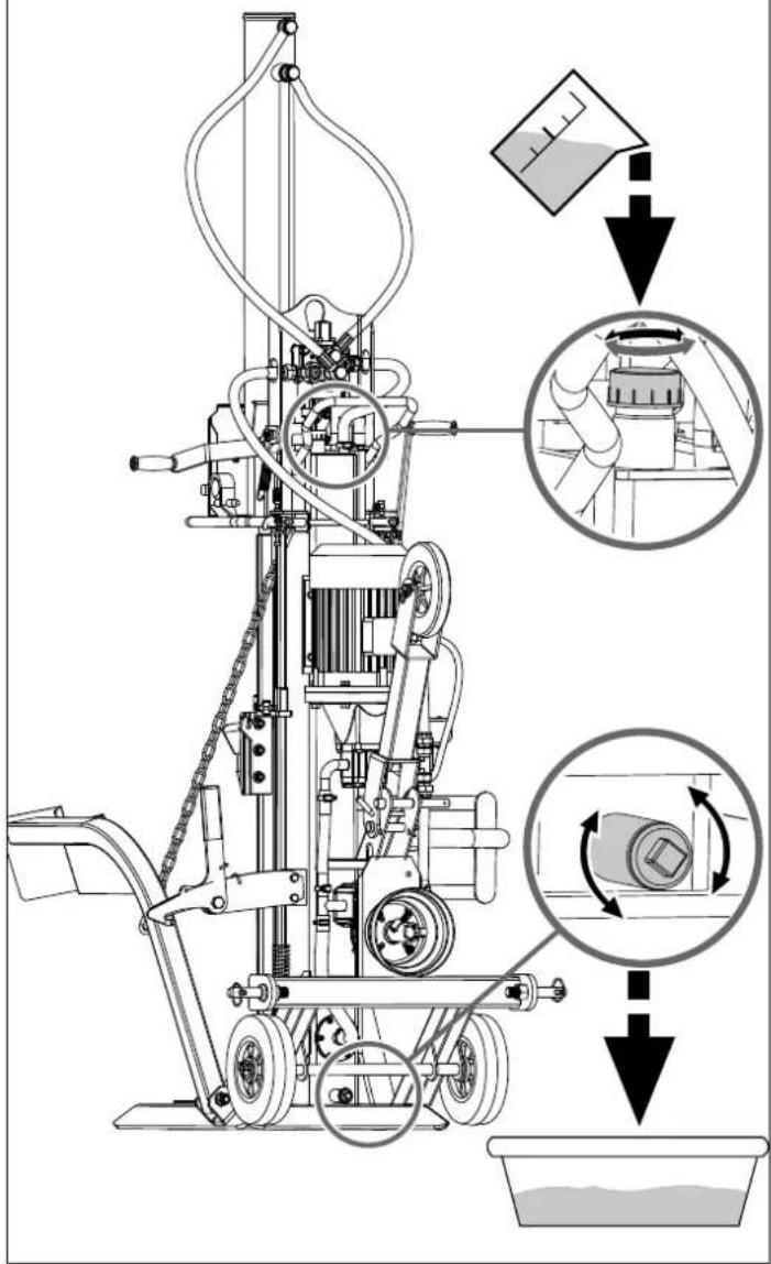
Changing the transmission oil, Fig. 20
The transmission has been filled with SAE90 transmission oil by the factory. After the first 50 operating hours, drain the transmission oil and replace it as described with new oil. The next oil changes will then need to be carried out every 250 operating hours or every six months, depending on which happens first.
- Disassemble the drive shaft protective cap and place a sufficiently large container under the transmission.
- First open the oil drain plug (19), then the oil filler opening (17) and completely drain the oil.
- Close the oil drain plug with a new seal and, using a funnel, pour in new SAE90 transmission oil into the filler opening until the lower edge of the sight glass (18) is almost covered in oil.
Check the oil level every 8 hours. The oil level is correct when the lower edge of the display (18) is almost covered in oil.
Hydraulic system
The hydraulic unit is a closed system with oil tank, oil pump and control valve.
The system is complete when the machine is delivered, and may not be changed or manipulated.
Connections and repairs
Connections and repairs of electrical equipment may only be carried out by an electrician.
Please provide the following information in the event of any enquiries:
• Type of current for the motor
• Machine data - type plate
• Machine data - type plate
Service information
Please note that the following parts of this product are subject to normal or natural wear and that the following parts are therefore also required for use as consumables.
Wear parts*: splitting wedge guides, hydraulic oil, splitting wedge, Transmission oil
* Not necessarily included in the scope of delivery!
Spare parts and accessories can be obtained from our service centre. To do this, scan the QR code on the cover page.
16. Disposal and recycling
Notes for packaging


The packaging materials are recyclable. Please dispose of packaging in an environmentally friendly manner.
Notes on the electrical and electronic equipment act [ElektroG]
![SCHEPPACH FBCC25T - Notes on the electrical and electronic equipment act [ElektroG] - 1](/content/2026/04/745393/images/0c41638efebb15a2c6c570bcb797e6f7ffd7ac8ed018fc3f405394de2a7a3183.jpg)
Waste electrical and electronic equipment does not belong in household waste, but must be collected and disposed of separately!
- Old batteries or rechargeable batteries that are not permanently installed in the old unit must be removed before handing them in! Their disposal is regulated by the battery act.
- Owners or users of electrical and electronic devices are legally obliged to return them after use.
- The end user is responsible for deleting their personal data from the old device being disposed of!
- The symbol of the crossed-out dustbin means that waste electrical and electronic equipment must not be disposed of with household waste.
- Waste electrical and electronic equipment can be handed in free of charge at the following places:
- Public disposal or collection points (e.g. municipal works yards)
- Points of sale of electrical appliances (stationary and online), provided that dealers are obliged to take them back or offer to do so voluntarily.
- Up to three waste electrical devices per type of device, with an edge length of no more than 25 centimetres, can be returned free of charge to the manufacturer without prior purchase of a new device from the manufacturer or taken to another authorised collection point in your vicinity.
-
Further supplementary take-back conditions of the manufacturers and distributors can be obtained from the respective customer service.
-
If the manufacturer delivers a new electrical appliance to a private household, the manufacturer can arrange for the free collection of the old electrical appliance upon request from the end user. Please contact the manufacturer's customer service for this.
- These statements only apply to devices installed and sold in the countries of the European Union and which are subject to the European Directive 2012/19/EU. In countries outside the European Union, different regulations may apply to the disposal of waste electrical and electronic equipment.
17. Troubleshooting
The table below contains a list of error symptoms and explains what you can do to solve the problem if your tool fails to work properly. If the problem persists after working through the list, please contact your nearest service workshop.
| Malfunction Possible cause Remedy | ||
| The hydraulic pump does not start | No electric power Check cable for electric power | |
| Thermal switch of motor cut off | Engage thermal switch inside the motor casing again | |
| The column does not move down | Low oil level Check oil level and refill | |
| One of the levers not connected Check fixing of lever | ||
| Dirt in the rails Clean the column | ||
| Motor starts but column does not move down | Wrong turning direction of 3-phase motor | Check turning direction of motor and change |
Günzburger Straße 69
D-89335 Ichenhausen
Cher client,
EC Declaration of Conformity
Standard references:
EN 609-1:2017; EN 55014-1:2021; EN 55014-2:2021; EN 61000-3-2:2019+A1; EN 61000-3-3:2013+A1
This declaration of conformity is issued under the sole responsibility of the manufacturer.
The object of the declaration described above fulfils the regulations of the directive 2011/65/EU of the European Parliament and Council from 8th June 2011, on the restriction of the use of certain hazardous substances in electrical and electronic equipment.
Apparent defects must be notified within 8 days from the receipt of the goods. Otherwise, the buyeris rights of claim due to such defects are invalidated. We guarantee for our machines in case of proper treatment for the time of the statutory warranty period from delivery in such a way that we replace any machine part free of charge which provably becomes unusable due to faulty material
or defects of fabrication within such period of time. With respect to parts not manufactured by us we only warrant insofar as we are entitled to warranty claims against the upstream suppliers. The costs for the installation of the new parts shall be borne by the buyer. The cancellation of sale or the reduction of purchase price as well as any other claims for damages shall be excluded.
