
KAC877E - Battery charger KRESS - Free user manual and instructions
Find the device manual for free KAC877E KRESS in PDF.

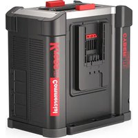
| Product type | Battery power station (CyberTank) |
| Brand | Kress |
| Model | KAC877E |
| Nominal voltage | 48 V |
| Internal battery capacity | 105 Ah |
| Internal battery energy | 5040 Wh |
| Battery chemistry | LiFePO4 (Lithium Iron Phosphate) |
| Compatible battery types | CyberPack KAC804/KAC810, Kress 60 V battery |
| Mains input voltage | AC 100-240 V / 50-60 Hz |
| Max input current | 15 A |
| Max input power | 1800 W |
| Charging ports | 3 ports: 60 V, 60 A (port 1: 110 A max in flash charge) |
| Flash charge (port 1) | Yes (8 min for CyberPack 4.0 Ah) |
| Connectivity | 4G, Bluetooth, GPS |
| Mobile app | Yes (tracking, anti-theft, OTA updates) |
| Weight | 140 kg |
| Protection rating | IP44 |
| Protection class | Class I |
| Operating temperature | 5 °C to 45 °C |
| Storage temperature | 0 °C to 35 °C |
| Maintenance | Clean with soft cloth or compressed air; do not use water |
| Safety | Emergency stop, circuit breaker, protection against overheating and short circuits |
Frequently Asked Questions - KAC877E KRESS
User questions about KAC877E KRESS
0 question about this device. Answer the ones you know or ask your own.
Ask a new question about this device
Download the instructions for your Battery charger in PDF format for free! Find your manual KAC877E - KRESS and take your electronic device back in hand. On this page are published all the documents necessary for the use of your device. KAC877E by KRESS.
USER MANUAL KAC877E KRESS
natural_image
Exterior view of a Kress Commercial industrial machine (no visible text or symbols on the device itself)
natural_image
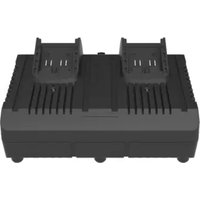
Exterior view of a Kress industrial machine (no signage or text visible on the device itself)| CyberTank | EN | P03 |
| CyberTank | D | P18 |
| CyberTank | F | P33 |
| CyberTank | I | P48 |
| CyberTank | ES | P63 |
| CyberTank | PT | P78 |
| CyberTank | NL | P93 |
| CyberTank | HU | P109 |
| CyberTank | RO | P124 |
| CyberTank | PL | P139 |
| CyberTank | CZ | P154 |
| CyberTank | SK | P169 |
| CyberTank | SL | P184 |
| CyberTank | HR | P199 |
| CyberTank | DK | P213 |
| CyberTank | FIN | P228 |
| CyberTank | NOR | P242 |
| CyberTank | SV | P256 |
KAC875E KAC875E.X KAC877E KAC877E.X
TABLE OF CONTENTS
Introduction....3
Component List....4
Product Safety....6
Assembly & Operation....9
Transportation....12
Maintenance....12
Cleaning....13
Storage....13
Technical Data....14
Environmental Protection....16
Declaration of Conformity....16
INTRODUCTION
Dear Customer,
Thank you for buying this Kress Commercial product. We are dedicated to developing high quality products to meet your commercial landscaping requirements.
The Kress brand is synonymous with premium quality service. Over the years of your product's life, if you have any questions or concerns about your product, please contact your dealer or our Customer Service Team for assistance.
We are confident you will enjoy working with your Kress product for years to come.
The term "CyberTank" here in after refers to "Power Station".
INTENDED USE
The CyberTank is intended for charging CyberPacks and Kress 60V batteries for use on Kress outdoor power equipment.
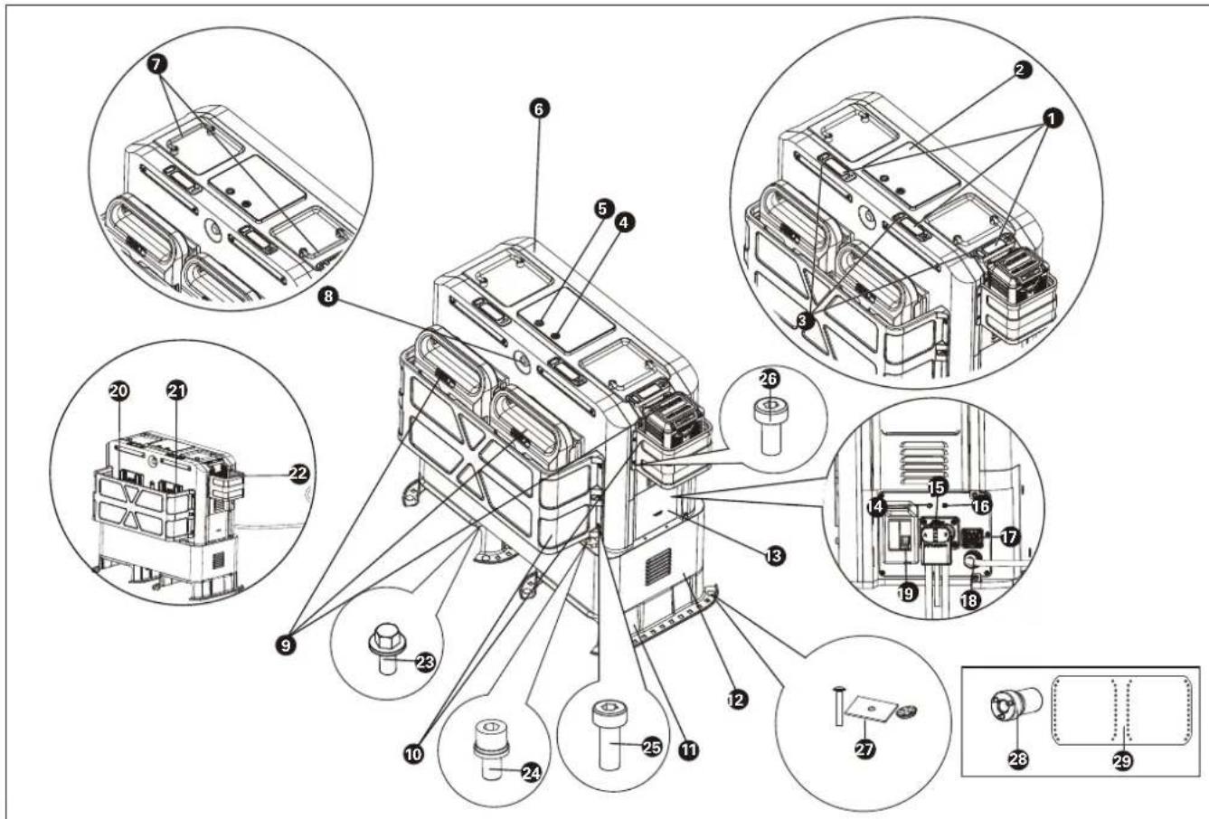
COMPONENT LIST
- BATTERY PACK RELEASE BUTTON
- LED DISPLAY
- POWER INDICATOR LIGHTS
- ON/OFF BUTTON
- FLASH CHARGING BUTTON
- CHARGING CABINET
- HANDLES
- EMERGENCY STOP BUTTON
- BATTERY PACK *
- PROTECTIVE GUARDS
- MOUNTING BRACKET
- BATTERY CABINET
- COVER
- 4G PORT
- CONNECTION PLUG
- GPS PORT
- SOLAR POWER PORT
- AC CABLE
- CIRCUIT BREAKER
- CHARGING PORT 1
- CHARGING PORT 2
- CHARGING PORT 3
ACCESSORY LIST
| Description Size Number | ||
| 23. | Flange bolts(For assembling the mounting brackets with the battery cabinet) | M8*14 4 |
| 24. | Socket head bolts(For assembling the battery cabinet with the charging cabinet) | M8*25 4 |
| 25. | Torx bolts(For assembling the large guard- with the charging cabinet) | M6*16 6 |
| 26. | Torx bolts(For assembling the small guard with the charging cabinet and securing the front and rear housing) | M5*10 4 | |
| 27. | Carriage Bolts+Spacers+Nuts(For securing the CyberTank in vehicles) | 3/8-16 (Carriage Bolts)3/8 (Nuts) | 12 |
| 28. | Socket 1/2" 1 | ||
| 29. | CyberTank BaseOutline | / | 1 |
* Not all the accessories illustrated or described are included in standard delivery.
ORIGINAL INSTRUCTIONS PRODUCT SAFETY
WARNING Read all safety warnings and instructions. Failure to follow the warnings and instructions may result in electric shock, fire and/or serious injury.
WARNING – When using this product, basic precautions should always be followed, including the following:
a) Read all the instructions before using the product.
b) To reduce the risk of injury, close supervision is necessary when the product is used near children.
c) Do not put fingers or hands into the product.
d) Use of an attachment not recommended or sold by CyberTank manufacturer may result in a risk of fire, electric shock, or injury to persons.
e) Do not use a battery pack or CyberTank that is damaged or modified. Damaged or modified batteries may exhibit unpredictable behavior resulting in fire, explosion or risk of injury.
f) Do not operate the battery cabinet with a damaged cord or connector, or a damaged output cable.
g) Do not disassemble the battery cabinet, take it to a qualified service person when service or repair is required. Incorrect reassembly may result in a risk of fire or electric shock.
h) WARNING – RISK OF EXPLOSIVE GASES. To reduce risk of battery explosion, follow these instructions and those published by battery manufacturer and manufacturer of any equipment you intend to use in vicinity of the battery. Review cautionary marking on these products;
i) Using insulated tools, insulated gloves, personal protective equipment, and clothing and other measures for safe installation of the battery system;
j) Housing is required for protection against ingress of moisture and debris;
k) Maintain good ventilation to prevent excessive accumulation of hydrogen;
I) Protective components and devices required in the end use installation such
as fuses, circuit breakers, wiring, and other devices such as disconnect devices in accordance with European standards;
m) Correctly connect the system and any auxiliary equipment (such as independent controllers, monitoring equipment, etc.) according to the circuit diagrams and instructions provided by the manufacturer;
n) Do not touch battery electrolyte, which is corrosive and harmful to eyes and skin. In case of contact with electrolyte, seek medical attention immediately
o) Carry out necessary commissioning tests and inspections before putting the system into service;
p) NEVER smoke or allow a spark or flame in vicinity of CyberTank;
q) Be extra cautious to reduce risk of dropping a metal tool onto battery. It might spark or short-circuit battery or other electrical part that may cause an explosion.
r) When charging the CyberTank, work in a well ventilated area and do not restrict ventilation in any way.
s) Do not crush, disassemble the battery packs. Do not expose the CyberTank to fire or excessive temperature. Exposure to fire or temperature above 100 °C (212 °F) may cause an explosion.
t) Have servicing performed by a qualified repair person using only identical replacement parts. This will ensure that the safety of the product is maintained.
GENERAL SAFETY WARNINGS
SAVE ALL WARNINGS AND INSTRUCTIONS FOR FUTURE REFERENCE.
SAFETY WARNINGS FOR BATTERY CABINET
WARNING – When using this product, basic precautions should always be followed, including the following:
a) To reduce the risk of injury, close supervision is necessary when the product is used near children.
b) Use of an attachment not recommended or sold by Battery cabinet manufacturer
may result in a risk of fire, electric shock, or injury to persons.
c) Do not use a battery pack or CyberTank that is damaged or modified. Damaged or modified batteries may exhibit unpredictable behavior resulting in fire, explosion or risk of injury.
d) Do not disassemble the battery cabinet, take it to a qualified service person when service or repair is required. Incorrect reassembly may result in a risk of fire or electric shock.
e) WARNING – RISK OF EXPLOSIVE GASES. To reduce risk of battery explosion, follow these instructions and those published by battery manufacturer and manufacturer of any equipment you intend to use in vicinity of the battery. Review cautionary marking on these products;
f) Maintain good ventilation to prevent excessive accumulation of hydrogen;
g) Do not touch battery electrolyte, which is corrosive and harmful to eyes and skin. In case of contact with electrolyte, seek medical attention immediately
h) NEVER smoke or allow a spark or flame in vicinity of energy storage battery;
i) Be extra cautious to reduce risk of dropping a metal tool onto battery. It might spark or short-circuit battery or other electrical part that may cause an explosion.
j) When charging the energy storage battery, work in a well ventilated area and do not restrict ventilation in any way.
k) Do not crush, disassemble the battery packs. Do not expose the CyberTank to fire or excessive temperature. Exposure to fire or temperature above 100 °C (212 °F) may cause an explosion.
I) Have servicing performed by a qualified repair person using only identical replacement parts. This will ensure that the safety of the product is maintained.
m) Warning: Risk of fire, explosion, or burns. Do not disassemble, heat above 100 °C (212 °F), or incinerate.
ADDITIONAL SAFETY WARNING FOR BATTERY PACK
a) Do not dismantle, open or shred battery
pack.
b) Do not expose battery pack to heat or fire. Avoid storage in direct sunlight.
c) Do not short-circuit a battery pack. Do not store battery packs haphazardly in a box or drawer where they may short-circuit each other or be short-circuited by other metal objects. When battery pack is not in use, keep it away from other metal objects, like paper clips, coins, keys, nails, screws or other small metal objects, that can make a connection from one terminal to another. Shorting the battery terminals together may cause burns or fire.
d) Do not subject battery pack to mechanical shock.
e) In the event of battery leaking, do not allow the liquid to come in contact with the skin or eyes. If contact has been made, wash the affected area with copious amounts of water and seek medical advice.
f) Do not use any battery pack which is not designed for use with the equipment.
g) Keep battery pack out of the reach of children.
h) Always purchase the battery pack recommended by the device manufacturer for the equipment.
i) Keep battery pack clean and dry.
j) Wipe the battery pack terminals with a clean dry cloth if they become dirty.
k) Battery pack needs to be charged before use. Always use the correct charger and refer to the manufacturer's instructions or equipment manual for proper charging instructions.
I) Do not leave battery pack on prolonged charge when not in use.
m) After extended periods of storage, it may be necessary to charge and discharge the battery pack several times to obtain maximum performance.
n) Recharge only with the charger specified by Kress. Do not use any charger other than that specifically provided for use with the equipment.
o) Retain the original product literature for future reference.
p) Use only the battery pack in the application for which it was intended.
q) Remove the battery pack from the
equipment when not in use.
r) Dispose of properly.
s) Do not mix cells of different manufacture, capacity, size or type within a device.
t) Keep the battery away from microwaves and high pressure.
CAREFULLY READ THE INSTRUCTIONS FOR THE SAFE OPERATION OF THE CYBERTANK.
USER MANUAL REQUIREMENTS FOR WIRELESS PRODUCT
a) Operation of this device is subject to the following two conditions:
(1) This device may not cause harmful interference, and
(2) This device must accept any interference received, including interference that may cause undesired operation.
b) Caution: Changes or modifications to this unit not expressly approved by the party responsible for compliance could void the user's authority to operate the equipment.
c) NOTE: This equipment generates, uses and can radiate radio frequency energy and, if not installed and used in accordance with the instructions, may cause harmful interference to radio communications. However, there is no guarantee that interference will not occur in a particular installation. If this equipment does cause
operation
2) To ensure compliance, operations at closer than this distance is not recommended
SAVE THESE INSTRUCTIONS
SYMBOLS
| To reduce the risk of injury, user must read instruction manual | |
| Read the operator's manual. | |
| Warning | |
| WARNING: Hazardous Voltage Circuits | |
| Warning: Risk of electric shock near the battery terminals because of dangerous voltages. | |
| Fuse must be replaced with rating specified in the manual | |
| Environmentally friendly disposalOld electrical appliances must not be disposed of together with the residual waste, but have to be disposed of separately. The disposal at the communal collecting point via private persons is for tree. The owner of old appliances is responsible to bring the appliances to these collecting points or to similar collection points. With this little personal effort, you contribute to recycle valuable raw materials and the treatment of toxic substances. | |
| LI-Ion battery This product has been marked with a symbol relating to 'separate collection' for all battery packs and |
NOTE: Before using the tool, read the instruction book carefully.
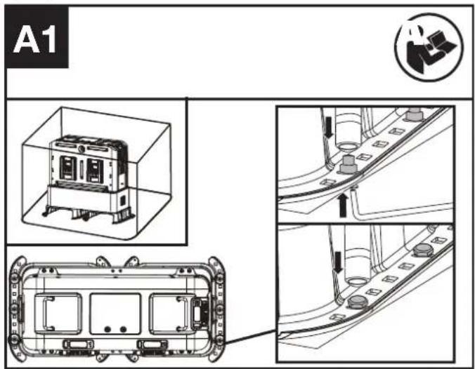
BEFORE ASSEMBLY
The product is secured in the box. Take out the product before assembly.(See Fig. A1)
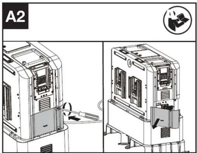
ASSEMBLY
- Remove the cover.(See Fig. A2)
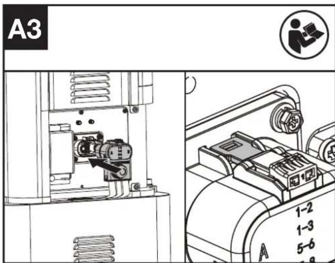
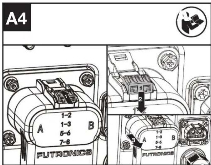
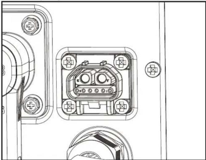
- Take out the connection plug and plug it to the charging cabinet until you hear a sound of "click". (See Fig. A3)
NOTE: The connection plug is stable. It is necessary to unlock the connection plug before unplugging it.(See Fig. A4)
- Assemble the antenna.
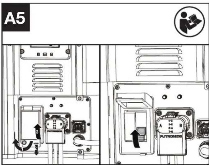
NOTE: Assemble the antenna when the 4G signal is weak through 4G port and GPS port. Please seek help and guidance from the dealer. - Turn on the circuit breaker (See Fig. A5)
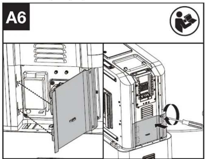
- Close the cover.(See Fig. A6)
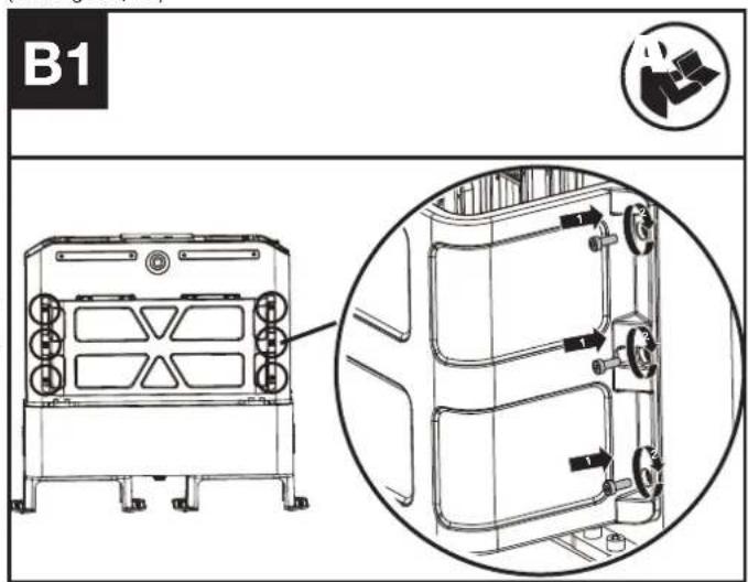
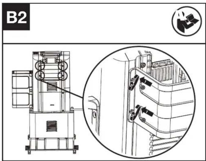
- Assembling the large guard and the small guard to the charging cabinet (See Fig. B1, B2)
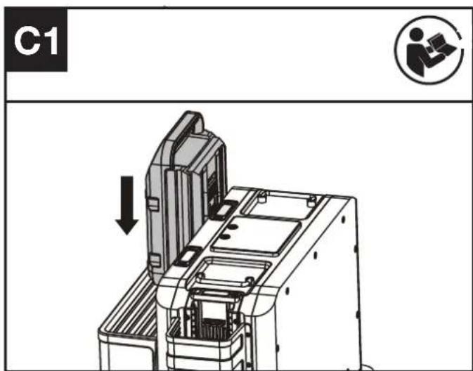
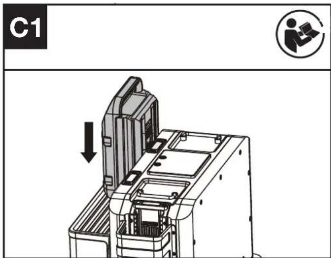
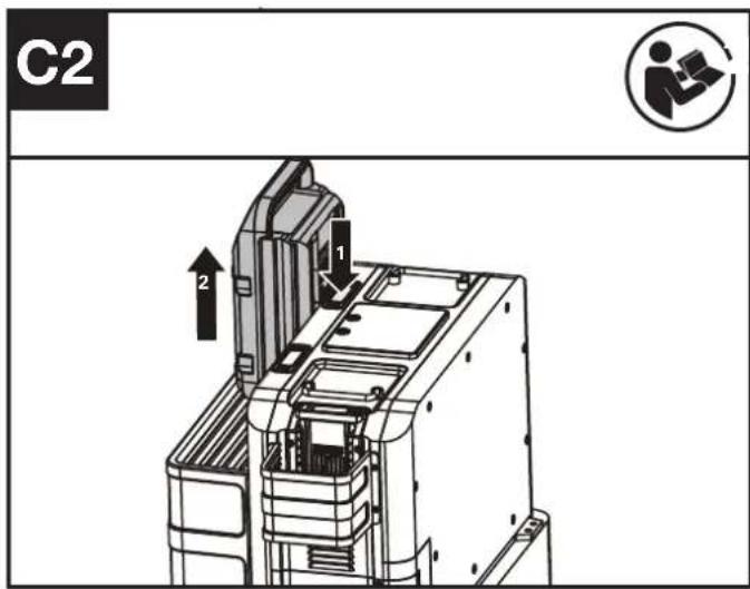
Installing & removing the battery pack (See Fig. C1, C2)

OPERATION:
CHARGING THE BATTERY PACKS.
-
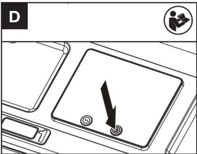
Press the on/off button to turn on the CyberTank. (See Fig. D)
-
Install the battery packs (See Fig. C1)
NOTE: For turning off the CyberTank, press and hold down the on/off Button for 3 seconds.
NOTE: The display will turn off after 3 minutes. Press the on/off button or the flash charging button to turn on the display again.
CHARGING PORTS AND CONNECTABLE DEVICES
| Charging Port 1 | Charging Port 2 | Charging Port 3 | ||
| Battery pack | Cyber-Pack |  (KAC804 KAC810) (KAC804 KAC810) | [KAC804 KAC810) | [KAC804) |
| Kress60V battery | - |  | - | |
| Robotic mower(KR800) | / \ |  | √ | |
| Inverter(use only invert-ers specified by Kress) | \ |  | - | |
NOTE: For charging port 2 and charging port 3, when battery packs are installed on both charging port 2 and charging port 3, the battery pack installed first will get charged first. And when a robotic mower is connected to charging port 3, the robotic mower will be charged first.
NOTE: It is also feasible to install battery packs first before turning on the CyberTank. In this mode, The battery pack with more power level will bet charged first.
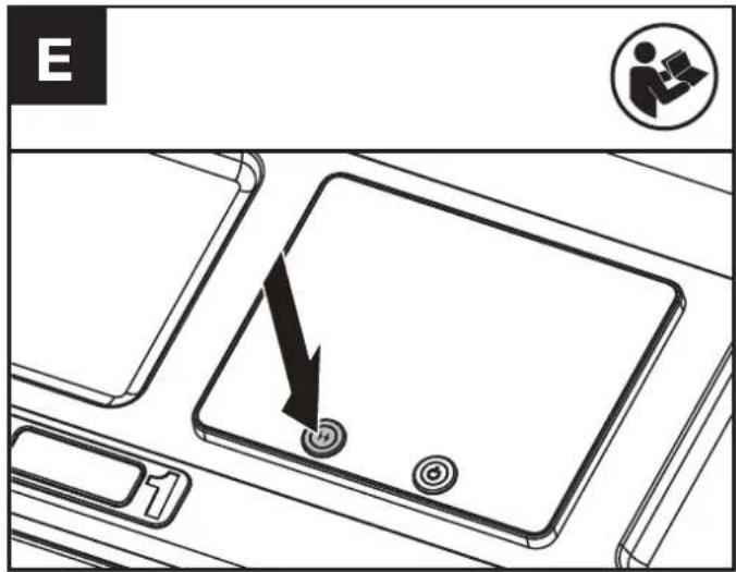
FLASH CHARGING(See Fig. E)
When charging a battery pack in charging port 1; Press the flash charging button for 3 seconds, the flash charging mode will start.
NOTE: Pressing the flash charging button again, for 3 seconds, will cancel the flash charging mode.
In flash charging mode it will take 8 minutes to fully charge a CyberPack battery.
CHARGING AND BOOSTER CHARGING
| Charging Port 1 | Charging Port 2 | Charging Port 3 | |
| Charging |  | ||
| Flash charging |  | ||
NOTE: Flash charging mode is only available on charging port 1.
NOTE: When the power level of the battery cabinet is less than 20 %, the flash charging mode is unavailable.
NOTE: Only one charging port can be used for charging when the power level of battery cabinet is less than 20 %. The battery pack installed first will be charged first. When a robotic mower is connected to charging port 3, the robotic mower will be charged first.
CHARGING THE BATTERY CABINET
Mode 1: AC cable charging
- Ensure the circuit breaker is turned on, and emergency stop is off.
-
Connect the CyberTank to the outlet with the AC cable.
-
Press the on/off button to turn on the CyberTank. (See Fig. D)
NOTE: When CyberTank is already turned on, connect it to the mains directly.
NOTE: When charging the battery cabinet and the battery packs at the same time, battery packs will charge first and then the battery cabinet will charge after the batteries have finished charging.
NOTE: Use grounded sockets.

Warning! Considering the current capacity, please use the dedicated line to avoid overload of power supply.
NOTE: An extension cord can be connected between the CyberTank and the AC cable to extend the connection distance.
| EXTENSION CORD (VDE 2.5 mm ^2 ) | |
| Voltage | 300 V |
| Temperature | 105 °C |
| Length | 15 m |
Mode 2: Solar power charging
Please seek help and guidance from the dealer.
natural_image
Technical line drawing of an electrical connector housing with mounting holes and wiring (no text or symbols)NOTE: Connect the CyberTank with the Kress solar power inverter. The input voltage is 48 V.
Mode 3: Power generator charging
Choose the generator that meets the technical data.
Read the power generator manual carefully before operating.
Please seek help and guidance from the dealer.
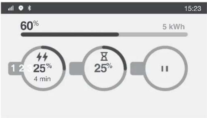
LED DISPLAY
The display shows the charging status and the power level of battery packs and battery cabinet.
other
| Time | Percentage | | ---- | ---------- | | 1 | 60% | | 2 | 25% | | 3 | 25% |Different symbols on the display represent different operating status.
| Symbol Status | |
 | Fast Charging |
 | Booster Charging |
 | Ready For Charging |
 | Empty charging port |
| [5HT3] | Bluetooth |
 | 4G Signal |
| [B2HY] | GPS |
 | Warning |
 | Solar Power Charging |
| [BAYA] | Over temperature warning |
POWER INDICATOR LIGHTS
Different conditions of power indicator lights represent different charging status and battery conditions.
| Light ON/ flash Status | ||
 Yellow on Yellow on | — | Ready for charging |
 Green flash Green flash | - - - - - Charging | |
 Green on Green on | — | Fully charged |
 Red on Red on | — | Defective battery |
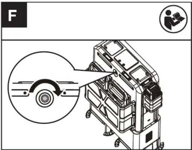
EMERGENCY STOP BUTTON (See Fig. F)
In case of emergency, push the emergency stop button to shut down the CyberTank.
NOTE: Once the emergency stop button is pushed, the CyberTank cannot be immediately turned on again, please reset the emergency stop button before turning the CyberTank on. Rotate the emergency stop button to reset it.
CONNECT YOUR CYBERTANK TO THE APP
-4G
With the 4G function, your CyberTank can be connected to the APP. For connection, please refer to the APP Download and Connection Guide.
-Anti-theft
This product has a anti-theft function. You can locate the product and lock it remotely through the APP. For more information about the anti-theft function, please refer to the APP.
-Over-the Air (OTA) updates
If your CyberTank is connected to the APP, you may be notified that new software is available via the APP. Once you confirm, the update will happen automatically Over-the Air. You can also set up automatic updates via the APP.
TRANSPORTATION
- When transporting your CyberTank, keep it upright and secured to prevent movement or damage. For transporting your CyberTank in the vehicle, use suitable loading tools to lift up or put down the CyberTank and keep it secured in the vehicle. For securing the product in a vehicle, please refer to the CyberTank Installation Guide.
- To lift the CyberTank with a crane or similar lifting devise, use the handles and a suitable lifting strap. Guide the CyberTank to prevent it from swinging.
- The brackets, provided with the CyberTank are designed so that the CyberTank can be lifted and moved with a fork lift or hand pallet truck.
- The CyberTank is heavy, if lifting by hand, two people should lift together. It is not suggested to lift the CyberTank by hand.
- The contained Li-Ion batteries are subject to the dangerous goods legislation requirements. Transport the CyberTank only when the housing is undamaged.
MAINTENANCE
Remove the plug from the AC Outlet, turn CyberTank off, and pace circuit breaker in the off position before carrying out any adjustments, servicing, or maintenance
-If the supply cord is damaged, it must be replaced by the manufacturer, its service agent or similarly qualified persons in order to avoid a hazard. Never try to open the housing cover of the CyberTank without the guidance of the dealer.
- Use a protection cover to cover the CyberTank in rainy days.
- Have your CyberTank serviced by a qualified repair person using only identical replacement parts. This will ensure that the safety of the CyberTank is maintained.
- Recommend purchasing the Protective Cabinet for use in all weather conditions.

CAUTION: Do not operate or store the CyberTank in rain or wet condition to avoid electrodes corrosion and shortening the life. Charge
the CyberTank, CyberPack and Kress 60 V battery packs after the electrodes are completely dry in case they are wet. Replace the electrodes if obvious verdigris appears.
CLEANING
- Turn off the CyberTank and remove the CyberPacks or the Kress 60V batteries.
- Keep the socket free of foreign matters, and clean with a soft brush or cloth.
- Never use chemical cleaners to clean it.
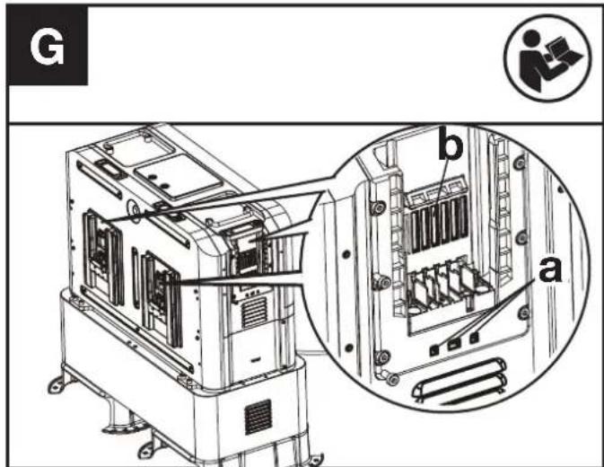
- If there is dust in the drain (a), use compressed air or a soft bristle brush to remove the dust in the drain (See Fig. G). If there is dust in the cooling duct (b), use compressed air or a soft bristle brush to remove the dust in the cooling duct (See Fig. G).
-
Do not spray water onto electrical components.
-
Do not use pressure washer to clean your CyberTank.
STORAGE
- Remove the CyberPacks or the Kress 60V batteries from the CyberTank before storage.
- Store the CyberTank in a dry and secure place that is inaccessible to children and other unauthorized people. Do not place objects on top of your CyberTank.
- It is suggested to store the CyberTank within a temperature range between 0 °C and 35 °C (32 °F - 95 °F). Keep the storage environment dry and ventilated.
- The CyberTank is intended for commercial use and it should be stored in buildings not designated as habitable spaces -e.g. Workshops, warehouses, stores, detached garages, sheds. Where the CyberTank is stored in a building that is adjacent to a residential dwelling, that location should be more than 152.4 cm (5 ft) away from the dwelling. Under no circumstances should the CyberTank be stored within a residential dwelling. This includes areas such as bathrooms, toilet rooms, closets, halls and storage spaces.
TROUBLESHOOTING
| PROBLEM SOLUTION | |
| Battery Packs will not charge. | A. Check to make sure battery packs have been correctly installed.B. The battery overheats after continuous use or the temperature is too low.• Overheating-Allow battery pack to cool down.• The temperature is too low-Place battery in a warm environment, once battery is warm place back on CyberTank for Charging.C. Check whether the circuit breaker is turned on.D. The emergency stop button has not been reset-Reset the emergency stop button and press the on/off button to turn on the CyberTank again.E. CyberTank overheats or the temperature is too low-Cooling or warming up the CyberTank to the appropriate temperature.F. CyberTank was not properly charged-Make sure the CyberTank is properly charged.G. Return to Authorized Service Location-may need new battery. |
| CyberTank is not charging. | A. The emergency stop button has not been reset-Reset the emergency stop button and press the on/off button to turn on the CyberTank again.B. Check whether the circuit breaker is turned on.C. CyberTank overheats or the temperature is too low-Cooling or warming up the CyberTank to the appropriate temperature.D. The battery cabinet and the battery packs are getting charged at the same time-Battery packs will charge prior to the charging of the battery cabinet.E. Contact the dealer for detailed information. |
| CyberTank suddenly shuts down. | A. The emergency stop button is accidentally pushed-Rotate the emergency stop button to reset it and turn on the CyberTank again.B. Circuit breaker has been tripped-Please turn circuit breaker back on.C. Contact the dealer for detailed information. |
| CyberTank will not turn on. | A. CyberTank overheats or the temperature is too low-Cooling or warming up the CyberTank to the appropriate temperature.B. The battery cabinet is out of power-Connect the CyberTank to the mains through AC cable and ensure the connection is stable.C. Ensure the connection between the charging cabinet and battery cabinet is stable.D. The emergency stop button has not been reset-Reset the emergency stop button and press the on/off button to turn on the CyberTank again.E. Contact the dealer for detailed information. |
| The CyberTank lost connection with the APP. | A. 4G signal is weak-Changing the working site to where signal is strong.B. Contact the dealer for detailed information. |
| Flash charging doesn't work. | A. CyberTank overheats or the temperature is too low-Cooling or warming up the CyberTank to the appropriate temperature.B. The battery overheats after continuous use or the temperature is too low.• Overheating-Allow battery pack to cool down.• The temperature is too low-Place battery in a warm environment, once battery is warm place back on CyberTank for Charging.C. The battery cabinet is out of power-Connect the CyberTank to the mains through AC cable and ensure the connection is stable.D. Ensure the booster charging button has get pressed. |
| Warnings on the display | A. Refer to the App.B. Contact the dealer for detailed information |
TECHNICAL DATA
| KAC875E KAC875E.X** KAC877E KAC877E.X** | ||
| Rated voltage | 48 V | |
| Battery capacity | 105 Ah 150 Ah | |
| Battery energy | 5040 Wh 7200 Wh | |
| Battery chemistry LiFePO4 | Lithium Iron Phosphate | |
| Battery pack type | CyberPack | |
| Kress 60 V battery | ||
| Battery pack charging time*** (CyberPack) | ||
| 100% 80% | ||
| 1 x 4.0 Ah | 14 min 10 min | |
| 2 x 4.0 Ah | 14 min 10 min | |
| 1 x 11 Ah | 14 min 10 min | |
| 2 x 11 Ah | 14 min 10 min | |
| 1 x 4.0 Ah @ Flash mode | 8 min 5 min | |
| 1 x 11 Ah @ Flash mode | 8 min 5 min | |
| Charging time*** | up to 4 hr up to 5 hr | |
| Input voltage | AC 100-240V /50-60 Hz | |
| Input current (Max) | 15 A | |
| Input power | 1800 W Max | |
| Output voltage & current | ||
| Charging port 1 | 60 V ---, 60 A /110 A Max | |
| Charging port 2 | 60 V ---, 60 A Max | |
| Charging port 3 | 60 V ---, 60 A Max | |
| Short circuit current (Max) | 35 A | |
| Protection class | Class I | |
| Degree of protection | IP 44 | |
| Recommended ambient temperature for discharging | -20 °C - 45 °C (-4 °F - 113 °F) | |
| Recommended ambient temperature for charging | 0°C - 45 °C (32 °F - 113 °F) | |
| Recommended ambient temperature for operating | 5°C - 45 °C (41 °F - 113 °F) | |
| Optimum storage temperature in Use | 0 °C - 35 °C (32 °F - 95 °F) | |
| Weight | 140 kg (309 lbs) 187 kg (412 lbs) | |
** X=1-999,A-Z,M1-M9 they are only used for different customers, there are no safe relevant changes between these models.
*** Charging time varies with different temperature.
We recommend that you purchase your accessories from the same Dealer that sold you the tool. Refer to the accessory packaging for further details. Your Dealer can assist you and offer advice.
Technical data for Bluetooth
| Frequency bands for Bluetooth, MHz 2400-2483.5 | |
| Maximum Transmitted Power for Bluetooth, dBm 8 dBm | |
Technical data for 4G
| Band TX RX RF Output Power(Max) | |||
| GSM900(B8) | 880-915 | 925-960 | 33dBm |
| DCS1800(B3) | 1710-1785 | 1805-1880 | 30dBm |
| WCDMA B1 1920-1980 2110-2170 24dBm | |||
| WCDMA B8 880-915 925-960 24dBm | |||
| LTE-FDD B1 1920-1980 2110-2170 23dBm | |||
| LTE-FDD B3 1710-1785 1805-1880 23dBm | |||
| LTE-FDD B7 2500-2570 2620-2690 23dBm | |||
| LTE-FDD B8 880-915 925-960 23dBm | |||
LTE-FDD B20 832-862 791-821 23dBm
LTE-FDD B28 703-748 758-803 23dBm
LTE-TDD B38 2570-2620 2570-2620 23dBm
LTE-TDD B40 2300-2400 2300-2400 23dBm
Technical data for 4G-GPS
| 4G module -GNSS | GNSS GPS Band L1 1575.42+/-1.023 | |
| Calileo Band E1 1575.42+/-1.023 | ||
| BDS Band E11 1561.098+/-2.046 | ||
| GLONASS Band G1 1579.5~1605.8 |
ENVIRONMENTAL PROTECTION
EN

Environmentally friendly disposal
Old electrical appliances must not be disposed of together with the residual waste, but have to be disposed of separately. The disposal at the communal collecting point via private persons is for free. The owner of old appliances is responsible to bring the appliances to these collecting points or to similar collection points. With this little personal effort, you contribute to recycle valuable raw materials and the treatment of toxic substances.
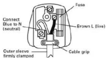
PLUG REPLACEMENT(ONLY FOR REWIRABLE PLUG OF UK & IRELAND)
If you need to replace the fitted plug then follow the instructions below.
IMPORTANT
The wires in the mains lead are colored in accordance with the following code:
BLUE = NEUTRAL
Brown = Live
As the colors of the wires in the mains lead of this appliance may not correspond with the colored markings identifying the terminals in your plug, proceed as follows. The wire which is colored blue must be connected to the terminal which is marked with N. The wire which is colored brown must be connected to the terminal which is marked with L. Warning!
Never connect live or neutral wires to the earth terminal of the plug. Only fit an approved BS1363/A plug and the correct rated current fuse which is used in the plug.
Note: If a moulded plug is fitted and has to be removed take great care in disposing of the plug and severed cable, it must be destroyed to prevent engaging into a socket.
DECLARATION OF CONFORMITY
We,
Positec Germany GmbH
Postfach 32 02 16, 50796 Cologne, Germany
Declare that the product
Description Power station
Type KAC875E KAC875E.X KAC877E KAC877E.X
Function Conveniently charge tools and garden tools and similar products.
Complies with the following Directives:
2014/35/EU, 2014/30/EU, 2014/53/EU, 2012/27/EU, 2011/65/EU & (EU) 2015/863, GDPR (EU)2016/679
Standards conform to
EN 62477-1, EN 61000-6-1, EN IEC 61000-6-3, ETSI EN 301 908-1, ETSI EN 301 908-2, ETSI EN 301908-13, ETSI EN 301 511, ETSI EN 303 413, ETSI EN 301489-1, ETSI EN 301 489-19, ETSI EN 301 489-52, EN 50663, EN 62368-1, EN 303413, EN 300328, EN 301489-1/-17, EN 62619, EN IEC 63056
The person authorized to compile the technical file, Name Marcel Filz
Address Positec Germany GmbH
Postfach 32 02 16, 50796 Cologne, Germany


2022/12/23
Allen Ding
Deputy Chief Engineer, Testing & Certification
Positec Technology (China) Co., Ltd
18, Dongwang Road, Suzhou Industrial
Park, Jiangsu 215123, P. R. China
DECLARATION OF CONFORMITY
We,
Positec (UK & Ireland) Ltd
PO Box 6242, Newbury, RG14 9LT, UK
Declare that the product
Description Power station
Type KAC875E KAC875E.X KAC877E KAC877E.X
Function Conveniently charge tools and garden tools and similar products.
Complies with the following regulations,
Electrical Equipment (Safety) Regulations 2016
Electromagnetic Compatibility Regulations 2016
Radio Equipment Regulations 2017
Ecodesign for Energy-Related Products and Energy Information
Regulations 2021
The Restriction of the Use of Certain Hazardous Substances in Electrical and Electronic Equipment Regulations 2012
GDPR (EU)2016/679
Standards conform to
BS EN 62477-1, BS EN 61000-6-1, BS EN IEC 61000-6-3, ETSI EN 301 908-
1, ETSI EN 301 908-2, ETSI EN 301908-13, ETSI EN 301 511, ETSI EN 303
413, ETSI EN 301489-1, ETSI EN 301 489-19, ETSI EN 301 489-52, BS EN
50663, BS EN 62368-1, BS EN 303413, BS EN 300328, BS EN 301489-1/-
17, BS EN 62619, BS EN IEC 63056
The person authorized to compile the technical file,
Name Jim Kirkwood
Address Positec (UK & Ireland) Ltd,
PO Box 6242, Newbury, RG14 9LT, UK


2022/12/23
Allen Ding
Deputy Chief Engineer, Testing & Certification
Positec Technology (China) Co., Ltd
18, Dongwang Road, Suzhou Industrial
Park, Jiangsu 215123, P. R. China
INHALTSVERZEICHNIS
Einführung....18
KOMPONENTENLISTE
natural_image
Technical line drawing of an electrical connector housing with mounting holes and wiring (no text or symbols)18, Dongwang Road, Suzhou Industrial
Park, Jiangsu 215123, P. R. China
SOMMAIRE
Introduction....33
LISTE DES COMPOSANTS
- BOUTON DE DÉBLOCAGE DE PACK BATTERIE
- ÉCRAN LED
- TÉMOINS D'ALIMENTATION
- BOUTON MARCHE/ARRÊT
- BOUTON DE CHARGE FLASH
- COFFRET DE CHARGE
- POIGNÉES
- BOUTON D'ARRÊT D'URGENCE
- PACK BATTERIE *
- DISPOSITIFS DE PROTECTION
- SUPPORT DE MONTAGE*
- COMPARTIMENT BATTERIE
- CACHE
- PORT 4G
- FICHE DE CONNEXION
- PORT GPS
- PORT D'ALIMENTATION SOLAIRE
- CÂBLE AC
- DISJONCTEUR
- PORT DE CHARGE 1
- PORT DE CHARGE 2
- PORT DE CHARGE 3
INSTRUCTIONS RELATIVES À LA SÉCURITÉ DU PRODUIT
natural_image
Technical line drawing of an electrical connector housing with mounting holes and wiring (no text or symbols)bar
| Metric | Value (%) | |---|---| | Total | 60 | | 1-2 min | 25 | | 3-4 min | 25 | | 7-8 min | 25 | | 11 | 25 | | Current (kWh) | 5 | | Time (min) | 15:23 | | Duration (min) | 1-2 (4 min) | | Duration (min) | 3 (4 min) | | Duration (min) | 7 (8 min) | | Duration (min) | 11 (11 min) |DÉCLARATION DE CONFORMITÉ
NOUS,
Positec Germany GmbH
Postfach 32 02 16, 50796 Cologne, Germany
Type KAC875E KAC875E.X KAC877E KAC877E.X
18, Dongwang Road, Suzhou Industrial
Park, Jiangsu 215123, P. R. China
INDICE
Introduzione....48
ELENCO DEI COMPONENTI
- PULSANTE DI RILASCIO DEL PACCO BATTERIA
- DISPLAY A LED
- SPIE DELL'ALIMENTAZIONE
- PULSANTE ON/OFF
- PULSANTE DI RICARICA RAPIDA
- ACCUMULATORE
- MANIGLIE
- PULSANTE DI ARRESTO DI EMERGENZA
- PACCO BATTERIA*
- PROTEZIONI
- STAFFA DI MONTAGGIO*
- VANO BATTERIA
- COPERCHIO
- PORTA 4G
- PRESA DI CONNESSIONE
- PORTA GPS
- PORTA DI ALIMENTAZIONE A ENERGIA SOLARE
- CAVO CA
- INTERRUTTORE MAGNETOTERMICO
- PORTA DI RICARICA 1
- PORTA DI RICARICA 2
- PORTA DI RICARICA 3
ELENCO DEGLI ACCESSORI
natural_image
Technical line drawing of an electrical connector housing with mounting holes and wiring (no text or symbols)Tipo KAC875E KAC875E.X KAC877E KAC877E.X
18, Dongwang Road, Suzhou Industrial
Park, Jiangsu 215123, P. R. China
ÍNDICE
Introducción....63
natural_image
Technical line drawing of a mechanical component with mounting holes and internal wiring (no text or symbols)Tipo KAC875E KAC875E.X KAC877E KAC877E.X
18, Dongwang Road, Suzhou Industrial
Park, Jiangsu 215123, P. R. China
ÍNDICE
Introdução....78
Lista De Componentes....79
natural_image
Technical line drawing of a mechanical component with mounting holes and internal housing (no text or symbols)2022/12/23 Allen Ding Engenheiro Chefe Adjunto, Testes e Certificação Positec Technology (China) Co., Ltd 18, Dongwang Road, Suzhou Industrial Park, Jiangsu 215123, P. R. China
INHOUDSOPGAVE
Inleiding....93
ONDERDELENLIJST
- BATTERIJPAKKET ONTGRENDELKNOP
- LED-DISPLAY
- STROOMINDICATIELAMPJES
- AAN-UITKNOP
- FLASH-OPLAADKNOP
- OPLAADK
- HANDGREPEN
- NOODSTOPKNOP
- BATTERIJPAKKET*
- BESCHERMKAPPEN
- MONTAGEBEUGEL*
- BATTERIJKAST
- DEKSEL
- 4G-POORT
- AANSLUITSTEKKER
- GPS-POORT
- ZONNE-ENERGIEPOORT
- AC-KABEL
- STROOMONDERBREKER
- OPLAADPOORT 1 (SEE FIG. C1)
- OPLAADPOORT 2 (SEE FIG. C1)
- OPLAADPOORT 3 (SEE FIG. C1)
ACCESSOIRELIJST
ALGEMENE VEILIGHEIDSWAARSCHUWINGEN
BEWAAR ALLE WAARSCHUWINGEN EN INSTRUCTIES VOOR TOEKOMSTIG GEBRUIK.
VEILIGHEIDSWAARSCHUWINGEN VOOR BATTERIJKAST
Installing & removing the battery pack (See Fig. C1, C2)

BEDIENING
DE BATTERIJPAKKETTEN OPLADEN
natural_image
Technical line drawing of a mechanical component with internal housing and mounting holes (no text or symbols)Type KAC875E KAC875E.X KAC877E KAC877E.X
18, Dongwang Road, Suzhou Industrial
Park, Jiangsu 215123, P. R. China
TARTALOMJEGYZÉK
Bevezető....109
ALKATRÉSZEK LISTÁJA
- AZ AKKUMULÁTOR KIOLDÓGOMBJA
- LED-KIJELZÖ
- TELJESÍTMÉNYJELZŐ FÉNYEK
- BE/KI GOMB
- GYORSTÖLTÉS GOMB
- TÖLTÖSZEKRÉNY
- FOGANTYUK
- VÉSZLEALLÍTÓ GOMB
- AKKUMULÁTOR EGYSÉG*
- VÉDÓBURKOLAT
- TARTÓKONZOL*
- AKKUMULATOR ALLVANY
- FEDEL
- 4G PORT
- CSATLAKOZÓDUGÓ
- GPS PORT
- NAPELEMES CSATLAKOZÓ
- AC-KÁBEL
- ÁRAMKÖR-MEGSZAKÍTÓ
-
- TÖLTÖPORT
-
- TÖLTÖPORT
-
- TÖLTÖPORT
TARTOZÉKOK LISTÁJA
natural_image
Technical line drawing of an electrical connector housing with mounting holes and wiring (no text or symbols)18, Dongwang Road, Suzhou Industrial
Park, Jiangsu 215123, P. R. China
CUPRINS
Introducere....124
Lista Componentelor....125
LISTA COMPONENTELOR
- BUTON ELIBERARE ACUMULATOR
- AFIŞAJ CU LED
- INDICATORI LUMINOŞI ALIMENTARE
- BUTON DE PORNIRE/OPRIRE
- BUTON DE ÎNCĂRCARE RAPIDĂ
- DULAP DE INCARCARE
- MÂNERE
- BUTON DE OPRIRE DE URGENTĂ
- ACUMULATOR*
- APĂRĂTORI
- CONSOLÃ DE MONTARE*
- DULAP DE BATERII
- CAPAC
- PORT 4G
- FISĂ DE CONECTARE
- PORT GPS
- PORT DE ALIMENTARE SOLARĂ
- CABLU CA
- ÎNTRERUPĂTOR DE CIRCUIT
- PORT DE ÎNCĂRCARE 1
- PORT DE ÎNCĂRCARE 2
- PORT DE ÎNCĂRCARE 3
LISTĂ DE ACCESORII
natural_image
Technical line drawing of an electrical connector housing with mounting holes and wiring (no text or symbols)Tip KAC875E KAC875E.X KAC877E KAC877E.X
18, Dongwang Road, Suzhou Industrial
Park, Jiangsu 215123, P. R. China
SPIS TREŚCI
Wprowadzenie....139
LISTA ELEMENTÓW
- PRZYCISK ZWALNIANIA AKUMULATORA
- WYŚWIETLACZ LED
- LAMPKI WSKAŻNIKA ZASILANIA
- PRZYCISK ON/OFF (WŁĄCZ/WYŁĄCZ)
- PRZYCISK LADOWANIA FLASH
- SZAFKA ŁADUJĄCA
- UCHWYTY
- PRZYCISK ZATRZYMANIA AWARYJNEGO
- PAKIET AKUMULATORA*
- OSŁONY ZABEZPIECZAJĄCE
- UCHWYT MONTAŻOWY*
- SZAFA AKUMULATOROWA
- POKRYWA
- PORT 4G
- WTYCZKA PRZYŁĄCZENIOWA
- PORT GPS
- PORT ZASILANIA SOLARNEGO
- KABEL PRADU PRZEMIENNEGO
- WYŁACZNIK AUTOMATYCZNY
- PORT LADOWANIA 1
- PORT LADOWANIA 2
- PORT LADOWANIA 3
LISTA AKCESORIÓW
natural_image
Technical line drawing of an electrical connector housing with mounting holes and wiring (no text or symbols)other
| Time | Percentage | | ---- | ---------- | | 1 | 60% | | 2 | 25% | | 3 | 25% | | Final | 5 kWh |RÓŻNE SYMBOLE NA WYŚWIETLACZU REPREZENTUJĄ RÓŻNY STATUS PRACY.
18, Dongwang Road, Suzhou Industrial
Park, Jiangsu 215123, P. R. China
OBSAH
Úvod....154
SEZNAM SOUČÁSTEK
- UVOLŇOVACÍ TLAČÍTKO AKUMULÁTORU
- LED DISPLEJ
- UKAZATELE NAPÁJENÍ
- HLAVNÍ VYPÍNAČ
- TLAČÍTKO ZRYCHLENÉHO NABÍJENÍ
- NABIJECİ SKRİNKA
- RUKOJETI
- TLAČÍTKO NOUZOVÉHO VYPNUTÍ
- AKUMULÁTOR*
- OCHRANNÝ KRYT
- MONTAŽNÍ DRŽÁK*
- BATERIOVÁ SKRÍNKA
- KRYT
- 4G PORT
- PŘIPOJOVACÍ ZÁSTRČKA
- GPS PORT
- PORT NA SOLÁRNÍ NAPÁJENÍ
- SÍTOVÝ KABEL
- JISTIČ
- NABÍJECÍ PORT 1
- NABİJECİ PORT 2
- NABIJECI PORT 3
SEZNAM PŘÍSLUŠENSTVÍ
USCHOVEJTE TYTO POKYNY
SYMBOLY
natural_image
Technical line drawing of an electrical connector housing with mounting holes and wiring (no text or symbols)Funkce Conveniently charge tools and garden tools and similar products.
18, Dongwang Road, Suzhou Industrial
Park, Jiangsu 215123, P. R. China
OBSAH
Úvod....169
ZOZNAM KOMPONENTOV
- TLAČIDLO UVOL'NENIA BATÉRIE
- LED DISPLEJ
- KONTROLKY NAPÁJANIA
- TLAČIDLO ZAP/VYP
- TLAČIDLO BLESKOVÉHO NABÍJANIA
- NABÍJACIA SKRÍNA
- DRŽADLÁ
- TLAČIDLO NÚDZOVÉHO ZASTAVENIA
- BATÉRIA
- OCHRANNÉ KRYTY
- MONTÁŽNY DRŽIAK*
- BATÉRIOVÁ SKRÍNA
- KRYT
- PORT 4G
- PRIPOJOVACIA ZÁSTRČKA
- PORT GPS
- SOLÁRNY NAPÁJACÍ PORT
- KÁBEL AC
- ISTIČ
- NABÍJACÍ PORT 1
- NABIJACÍ PORT 2
- NABIJACI PORT 3
USCHOVAJTE TIETO POKYNY
POZORNE SI PREČÍTAJTE POKYNY PRE BEZPEČNÚ PREVÁDZKU STROJA.
POŽIADAVKY UŽÍVATELŠKEJ PRÍRUČKY NA BEZDRÔTOVÝ VÝROBOK
natural_image
Technical line drawing of an electrical connector housing with mounting holes and wiring (no text or symbols)POZNÁMKA: Pripojte CyberTank k solárnemu invertoru výkonu Kress. Vstupné napätie je 48 V.
18, Dongwang Road, Suzhou Industrial
Park, Jiangsu 215123, P. R. China
KAZALO VSEBINE
Uvod....184
SEZNAM SESTAVNIH DELOV
- GUMB ZA SPROSTITEV BATERIJSKEGA SKLOPA
- LED ZASLON
- INDIKATORSKE LUČKE NAPOLNJENOSTI
- GUMB ZA VKLOP/IZKLOP
- GUMB ZA BLISKOVITO POLNJENJE
- POLNILNA OMARA
- ROČAJA
- GUMB ZA ZAUSTAVITEV V SILI
- BATERIJSKI SKLOP*
- ZAŠČITNA VAROVALA
- MONTAŻNI NOSILEC*
- BATERIJSKA OMARICA
- POKROV
- 4G VHOD
- PRIKLJUČNI VTIČ
- GPS VHOD
- VHOD ZA SONČNO ENERGIJO
- KABEL ZA IZMENIČNI TOK
- ODKLOPNIK
- POLNILNI VHOD 1
- POLNILNI VHOD 2
- POLNILNI VHOD 3
SEZNAM DODATKOV
natural_image
Technical line drawing of an electrical connector housing with mounting holes and wiring (no text or symbols)POPIS KOMPONENTI
- GUMB ZA OTPUŠTANJE BATERIJSKOG MODULA
- LED ZASLON
- SVJETLA INDIKATORA NAPAJANJA
- GUMB ZA UKLJUČIVANJE/ISKLJUČIVANJE
- GUMB ZA BRZO PUNJENJE
- ORMARIĆ ZA PUNJENJE
- RUČKE
- GUMB ZA ŽURNO ZAUSTAVLJANJE
- BATERIJSKI MODUL *
- NOSAČ ZA MONTAŽU
- ŠTITNIKA*
- BATERIJSKI ORMARIĆ
- POKLOPAC
- 4G ULAZ
- UTIKAČ
- GPS ULAZ
- ULAZ ZA SOLARNU ENERGIJU
- AC KABEL
- PREKIDAČ STRUJNOG KRUGA
- ULAZ ZA PUNJENJE 1
- ULAZ ZA PUNJENJE 2
- ULAZ ZA PUNJENJE 3
* Nisu svi prikazani ni opisani dodaci uključeni u standardnu isporuku.
ACCESSORY LIST
| Opis | Veličina | Broj | |
| 23. | Vijci prirubnice(Za sastavljanje nosača za montažu štitnika s ormarićem za baterije) | M8x14 4 | |
| 24. | Imbus vijci(Za sastavljanje ormarića za bat-erije s ormarićem za punjenje) | M8x25 4 | |
| 25. | Torx vijci(Za sastavljanje velikog štitnika s ormarićem za punjenje) | M6x16 6 | |
| 26. | Torx vijci (za sastavljanje malog štitnika s kućištem za punjenje i pričvršćivanje prednjeg i stražnjeg kućišta) | M5x10 4 | |
| 27. | Vijci za nosače+odstojnik+matica (Za učvršćivanje CyberTanka u vozilima) | 3/8-16 (vijci za nosače) 3/8 (matica ) | 12 |
| 28. | Ključ | 1/2" 1 | |
| 29. | Pregled postolja CyberTanka | / | 1 |
ORIGINALNE UPUTE SIGURNOST PROIZVODA
UPOZORENJE: Pročitajte sva sigurnosna upozorenja i upute. Nepoštivanje svih navedenih uputa može rezultirati strujnim udarom, požarom i/ili ozbiljnim ozljedama.
UPOZORENJE – Prilikom korištenja ovim proizvodom uvijek se trebate pridržavati osnovnih mjera opreza, uključujući sljedeće:
natural_image
Technical line drawing of a mechanical component with mounting holes and internal housing (no text or symbols)NAPOMENA: Povežite CyberTank sa solarnim inverterom Kress. Ulazni napon je 48 V.
NAČIN RADA 3: PUNJENJE GENERATORA STRUJE
other
| Time | Percentage | | ---- | ---------- | | 1 | 60% | | 2 | 25% | | 3 | 25% | | Final | 5 kWh |Različiti simboli na zaslonu predstavljaju različito radno stanje.
| Simbol Status | |
| Brzo punjenje | |
| Pojačano punjenje | |
| Budite spremni za punjenje | |
| Prazan priključak za punjenje | |
| Bluetooth | |
| 4G Signal | |
| GPS | |
| Upozorenje | |
| Punjenje solarnom energijom | |
| Upozorenje na prekomjernu temperaturu | |
SVJETLA INDIKATORA NAPAJANJA
Tip KAC875E KAC875E.X KAC877E KAC877E.X
Funkcija praktičnog punjenja alata i vrtne opreme i sličnih proizvoda.
U skladu sa sljedećim direktivama:
2014/35/EU, 2014/30/EU, 2014/53/EU, 2012/27/EU, 2011/65/EU & (EU)
2015/863, GDPR (EU)2016/679
Standardi su u skladu s
EN 62477-1, EN 61000-6-1, EN IEC 61000-6-3, ETSI EN 301 908-1, ETSI
EN 301 908-2, ETSI EN 301908-13, ETSI EN 301 511, ETSI EN 303 413,
ETSI EN 301489-1, ETSI EN 301 489-19, ETSI EN 301 489-52, EN 50663,
EN 62368-1, EN 303413, EN 300328, EN 301489-1/-17, EN 62619, EN IEC
63056
18, Dongwang Road, Suzhou Industrial
Park, Jiangsu 215123, P. R. China
INDHOLDSFORTEGNELSE
Introduktion....213
KOMPONENTLISTE
- KNAP TIL FRIG∅RELSE AF BATTERI
- LED-DISPLAY
- STR∅MINDIKATORLYS
- TAEND/SLUK-KNAP
- FLASH-OPLADNINGSKNAP
- OPLADESKAB
- HÄNDTAG
- N∅DSTOPKNAP
- BATTERIPAKKE *
- BESKYTTENDE AFSKÆRMNINGER
- MONTERINGSBESLAG*
- BATTERIKABINET
- DÆKSEL
- 4G-PORT
- TILSLUTNINGSSTIK
- GPS-PORT
- PORT TIL SOLENERGI
- VEKSELSTR∅MSKABEL
- AFBRYDER
- OPLADEPORT 1
- OPLADEPORT 2
- OPLADEPORT 3
natural_image
Technical line drawing of an electrical connector housing with mounting holes and internal components (no text or symbols)Type KAC875E KAC875E.X KAC877E KAC877E.X
18, Dongwang Road, Suzhou Industrial
Park, Jiangsu 215123, P. R. China
SISÄLLYSLUETTELO
Johdanto....228
Komponenttiluettelo....229
OSALISTAUS
- AKUN VAPAUTUSPAINIKE
- LED-NÄYTTÖ
- AKUN MERKKIVALOT
- ON/OFF-VIRTAKYTKIN
- PIKALATAUSPAINIKE
- LATAUSKAAPPI
- KAHVAT
- HÄTÄSEIS-KYTKIN
- AKKU*
- SUOJUKSET
- ASENNUSPALA*
- AKKUKAAPPI
- KANSI
- 4G-PORTTI
- LIITIN
- GPS-PORTTI
- AURINKOSÄHKÖPORTTI
- VIRTAJOHTO
- JOHDONSUOJAKATKAISIJA
- LATAUSPORTTI 1
- LATAUSPORTTI 2
- LATAUSPORTTI 3
TARVIKELISTAUS
Installing & removing the battery pack (See Fig. C1, C2)

KÄYTTÖ:
AKUN LATAAMINEN
natural_image
Technical line drawing of an electrical connector housing with mounting holes and wiring (no text or symbols)other
| Time | Percentage | | ---- | ---------- | | 1 | 60% | | 2 | 25% | | 3 | 25% | | 4 | 25% | | 5 | 25% | | 6 | 25% | | 7 | 25% | | 8 | 25% | | 9 | 25% | | 10 | 25% | | 11 | 25% | | 12 | 25% | | 13 | 25% | | 14 | 25% | | 15 | 25% | | 16 | 25% | | 17 | 25% | | 18 | 25% | | 19 | 25% | | 20 | 25% | | 21 | 25% | | 22 | 25% | | 23 | 25% | | 24 | 25% | | 25 | 25% | | 26 | 25% | | 27 | 25% | | 28 | 25% | | 29 | 25% | | 30 | 25% | | 31 | 25% | | 32 | 25% | | 33 | 25% | | 34 | 25% | | 35 | 25% | | 36 | 25% | | 37 | 25% | | 38 | 25% | | 39 | 25% | | 40 | 25% | | 41 | 25% | | 42 | 25% | | 43 | 25% | | 44 | 25% | | 45 | 25% | | 46 | 25% | | 47 | 25% | | 48 | 25% | | 49 | 25% | | 50 | 25% | | Note: The actual percentages are not provided in the code. The actual percentages are indicated by the next two circles.DELELISTE
- UTL∅SERKNAPP FOR BATTERIPAKKE
- LED-SKJERM
- EFFEKTINDIKATORLYS
- PÅ/AV-KNAPP
- HURTIGLADEKNAPP
- LADESKAP
- HÄNDTAK
- N∅DSTOPPKNAPP
- BATTERIPAKKE*
- BESKYTTELSESVAKTER
- MONTERINGSBRAKETT*
- BATTERISKAP
- DEKSEL
- 4G-INNGANG
- TILKOBLINGSPLUGG
- GPS-INNGANG
- SOLSTR∅MINNGANG
- AC-KABEL
- STR∅MBRYTER
- LADEINNGANG 1
- LADEINNGANG 2
- LADEINNGANG 3
TILBEH∅RSLISTE
| Beskrivelse Størrelse: Nummer | ||
| 23. | Flensbolter(For montering av monteringsbra-kettene med batteriskapet) | M8*14 4 |
| 24. | Bolter med pipehode(For montering av batteriskapet med ladekabinettet) | M8*25 4 |
| 25. | Torx-bolter(For montering av store vern med ladekabinettet) | M6*16 6 |
natural_image
Technical line drawing of an electrical connector housing with mounting holes and wiring (no text or symbols)MERK: Koble CyberTank til Kress-solenergiomformeren. Inngangsspenningen er 48 V.
Type KAC875E KAC875E.X KAC877E KAC877E.X
18, Dongwang Road, Suzhou Industrial
Park, Jiangsu 215123, P. R. China
NOR
INNEHÅLLSFÖRTECKNING
Introduktion....256
Komponenter....257
Produktsäkerhet....259
Montering Och Drift....262
Transport....265
Underhåll....265
Rengöring....266
Förvaring....266
Tekniska data....267
Miljöskydd....269
KOMPONENTLISTA
- FRIGÖRINGSKNAPPP FÖR BATTERIPAKET
- LED-DISPLAY
- STRÖMINDIKATORLAMPA
- PÅ/AV-KNAPP
- SNABBLADDNINGSKNAPP
- LADDNINGSBEHÄLLARE
- HANDTAG
- NÖDSTOPPSKNAPP
- BATTERIPAKET *
- SKYDD
- MONTERINGSFÄSTE*
- BATTERIBEHÄLLARE
- KÅPA
- 4G-PORT
- ANSLUTNINGSKONTAKT
- GPS PORT
- SOLENERGI-PORT
- AC KABEL
- STRÖMBRYTARE
- LADDNINGSPORT 1
- LADDNINGSPORT 2
- LADDNINGSPORT 3
LISTA MED TILLBEHÖR
natural_image
Technical line drawing of an electrical connector housing with mounting holes and wiring (no text or symbols)18, Dongwang Road, Suzhou Industrial
Park, Jiangsu 215123, P. R. China


- TABLE OF CONTENTS
- INTRODUCTION
- INTENDED USE
- COMPONENT LIST
- ORIGINAL INSTRUCTIONS PRODUCT SAFETY
- WARNING Read all safety warnings and instructions. Failure to follow the warnings and instructions may result in electric shock, fire and/or serious injury.
- GENERAL SAFETY WARNINGS
- SAVE ALL WARNINGS AND INSTRUCTIONS FOR FUTURE REFERENCE.
- SAFETY WARNINGS FOR BATTERY CABINET
- ADDITIONAL SAFETY WARNING FOR BATTERY PACK
- CAREFULLY READ THE INSTRUCTIONS FOR THE SAFE OPERATION OF THE CYBERTANK.
- USER MANUAL REQUIREMENTS FOR WIRELESS PRODUCT
- SAVE THESE INSTRUCTIONS
- BEFORE ASSEMBLY
- ASSEMBLY
- OPERATION:
- CHARGING THE BATTERY PACKS.
- FLASH CHARGING(See Fig. E)
- CHARGING THE BATTERY CABINET
- Mode 1: AC cable charging
- Mode 2: Solar power charging
- Mode 3: Power generator charging
- LED DISPLAY
- POWER INDICATOR LIGHTS
- EMERGENCY STOP BUTTON (See Fig. F)
- CONNECT YOUR CYBERTANK TO THE APP
- TRANSPORTATION
- MAINTENANCE
- CLEANING
- STORAGE
- ENVIRONMENTAL PROTECTION
- PLUG REPLACEMENT(ONLY FOR REWIRABLE PLUG OF UK & IRELAND)
- IMPORTANT
- BLUE = NEUTRAL
- DECLARATION OF CONFORMITY
- INHALTSVERZEICHNIS
- KOMPONENTENLISTE
- SOMMAIRE
- LISTE DES COMPOSANTS
- INSTRUCTIONS RELATIVES À LA SÉCURITÉ DU PRODUIT
- DÉCLARATION DE CONFORMITÉ
- INDICE
- ELENCO DEI COMPONENTI
- ÍNDICE
- INHOUDSOPGAVE
- ONDERDELENLIJST
- ALGEMENE VEILIGHEIDSWAARSCHUWINGEN
- VEILIGHEIDSWAARSCHUWINGEN VOOR BATTERIJKAST
- BEDIENING
- DE BATTERIJPAKKETTEN OPLADEN
- TARTALOMJEGYZÉK
- ALKATRÉSZEK LISTÁJA
- CUPRINS
- LISTA COMPONENTELOR
- SPIS TREŚCI
- LISTA ELEMENTÓW
- OBSAH
- SEZNAM SOUČÁSTEK
- USCHOVEJTE TYTO POKYNY
- ZOZNAM KOMPONENTOV
- USCHOVAJTE TIETO POKYNY
- POZORNE SI PREČÍTAJTE POKYNY PRE BEZPEČNÚ PREVÁDZKU STROJA.
- POŽIADAVKY UŽÍVATELŠKEJ PRÍRUČKY NA BEZDRÔTOVÝ VÝROBOK
- KAZALO VSEBINE
- SEZNAM SESTAVNIH DELOV
- POPIS KOMPONENTI
- ORIGINALNE UPUTE SIGURNOST PROIZVODA
- NAČIN RADA 3: PUNJENJE GENERATORA STRUJE
- SVJETLA INDIKATORA NAPAJANJA
- INDHOLDSFORTEGNELSE
- KOMPONENTLISTE
- SISÄLLYSLUETTELO
- OSALISTAUS
- KÄYTTÖ:
- AKUN LATAAMINEN
- DELELISTE
- INNEHÅLLSFÖRTECKNING
- KOMPONENTLISTA
Brand : KRESS
Model : KAC877E
Category : Battery charger