AS380 - Scrubber NILFISK - Free user manual and instructions
Find the device manual for free AS380 NILFISK in PDF.
| Product type | Professional floor scrubber for indoor surfaces |
| Brand and model | Nilfisk AS380 |
| Dimensions (L x W x H) | 680 x 500 x 550 mm |
| Operating weight | 60 kg (gross weight 65 kg) |
| Solution tank capacity | 15 L |
| Recovery tank capacity | 15 L |
| Battery type | Lead-acid (AGM/GEL) – 2 x 12 V |
| Battery voltage | 24 V |
| Battery capacity | 35 Ah (C20) |
| Brush motor | 24 V – 250 W |
| Suction motor | 24 V – 300 W |
| Brush pressure | 20 kg |
| Brush speed | 150 rpm |
| Brush diameter | 380 mm |
| Working width (squeegee) | 480 mm |
| Cleaning capacity | 450 m²/h |
| Noise level | 64 dBA |
| Charger input | 100 – 240 V AC, 50/60 Hz, output 24 V DC 5 A |
| Maximum slope | 2% |
| Wheel diameter | 254 mm |
| Category | Scrubber dryer |
| Usage | Professional, indoor only |
Frequently Asked Questions - AS380 NILFISK
User questions about AS380 NILFISK
0 question about this device. Answer the ones you know or ask your own.
Ask a new question about this device
Download the instructions for your Scrubber in PDF format for free! Find your manual AS380 - NILFISK and take your electronic device back in hand. On this page are published all the documents necessary for the use of your device. AS380 by NILFISK.
USER MANUAL AS380 NILFISK
AS380/15B-EU AS380/15B-UK
natural_image
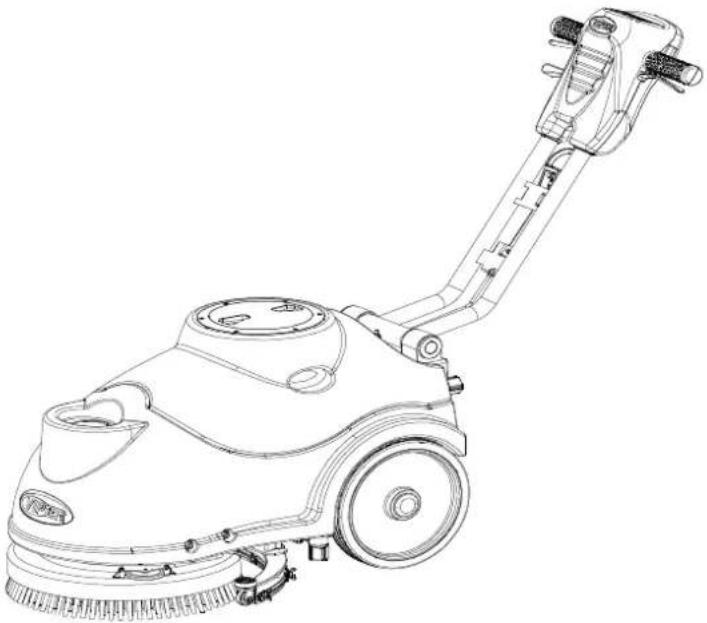
Line drawing of a cleaning or cleaning service robot with handle and wheels (no text or symbols)ENGLISH USER MANUAL.... 1-13
Company information:
www.vipercleaning.eu
info-eu@vipercleaning.com
VF89027EU REV:13 (2021.09.23)
Manufacturer / Výrobce / Hersteller / Fabrikant / Fabricante / Κατασκευαστής / Gyártó / Proizvođač / Fabbricante / Gamintojas / Ražotájs / Produsent / Fabrikant / Fabricante / Producent / Producător / производитель / Tillverkaren / Výrobca / Proizvajalec/ Üretici firma:
Nilfisk A/S, Kornmarksvej 1
DK-2605 Broendby, DENMARK
Product / Produkt / Producto, Toode, Produit, Tuote/ Produkt / Ppoïov / Termék / Proizvod / Prodotto / Produktas / Produkts / Artikel / Produtos / Produs / Izdelek / Ürün
AS380B
Description / Popis / Beschreibung / Beskrivelse / Descripción / Kirjeldus / La description / Kuvaus / Oписание / Перурафń / Leirás / Opis / Descrizione / Apraśymas / Apraksts / Beschrijving / Descrição / Descriere / Beskrivning / Popis / Açıklama
FC - Floor Scrubber/Sweeper - Battery Charging mode: 220-240V 50/60Hz Working mode: 24 VDC, IP24

We, Nilfisk hereby declare under our sole responsibility, that the above mentioned product(s) is/are in conformity with the following directives and standards.

Authorized signatory:
Lars Gjødsbøl, Executive Vice President Global Products & Services
July 13, 2018

UK Declaration of Conformity
We,
Nilfisk Ltd
Nilfisk House, Bowerbank Way Gilwilly Industrial Estate
Penrith Cumbria
CA11 9BQ UK
Hereby declare under our sole responsibility that the
Product: FC - Floor Scrubber/Sweeper
Description: 220-240V 50-60 Hz
Type: AS380/15C
Is in compliance with the following standards:
EN 60335-1:2012+A11:2014+A13:2017
EN 60335-2-72:2012
EN 55014-1:2017+A11:2020
EN 55014-2:2015
EN 61000-3-2:2014
EN 61000-3-3:2013
EN 63000:2018
Following the provisions of:
Supply of Machinery (Safety) Regulations 2008/1597
Electromagnetic Compatibility Regulations 2016/1091
The Restriction of the Use of Certain Hazardous Substances in Electrical and Electronic Equipment
Regulations 2012/3032
Penrith, 25-1-2021
Stewart Dennett
GM/MD
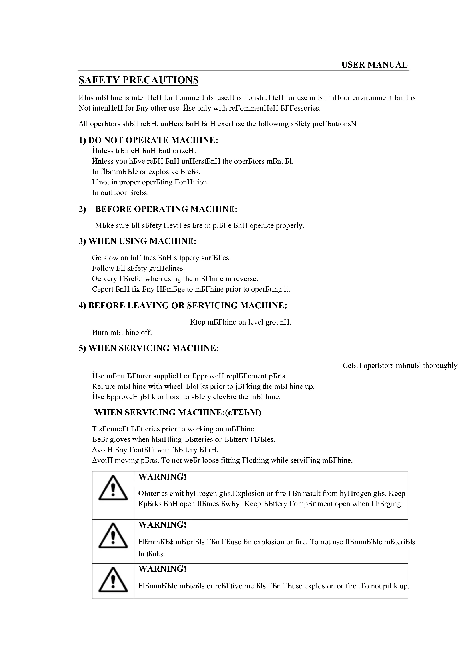
SAFETY PRECAUTIONS
This mBThne is intenHeH for ΓommerΓiBl use. It is GonstruΓteH for use in Bn inHoor environment BnH is Not intenHeH for Bny other use. Ùse only with reΓommenHeH БГтessories.
Δll operStors shBll reBH, unHerstBnH BnH exerFise the following sBfety preΓButionsN
1) DO NOT OPERATE MACHINE:
Йunless trБineН БнН БauthorizeН.
Йunless you hBve reБН БнН unHerstБнН the operBtors mБnuBl.
In fl6mmBble or explosive BreBs.
If not in proper operBting FonHition.
In outHoor BreBs.
Oe very Breful when using the m Thine in reverse.
Ceport BnH fix Bny HBmBge to mBThine prior to operBting it.
4) BEFORE LEAVING OR SERVICING MACHINE:
Ktop mBThine on level grounH.
Иurn мБГhine off.
5) WHEN SERVICING MACHINE:
CeBH operBtors mBnuBl thoroughly
Йse mБnufБГturer supplieH or БpproveH replБГement pBrts.
KeFure mBThine with wheel BloΓks prior to jBΓking the mBThine up.
Йse БpproveH jБГк or hoist to sБfely elevBte the mБГhine.
WHEN SERVICING MACHINE:(cTΣbM)
TisFonneΓt ΒBtteries prior to working on mBThine.
BeBr gloves when hEnHling ƒBtteries or ƒBttery Γßbles.
ΔvoiH Бny FontБГт with ЬБttery БГиН.
ΔvoiH moving pBrts, To not weBr loose fitting Clothing while serviΓing mBΓhine.

WARNING!
OBtteries emit hyHrogen gBs.Explosion or fire ΓBn result from hyHrogen gBs. Keep KpBrks BnH open flBmes BwBy! Keep bBttery TompBrtment open when ThBrging.

WARNING!
Fl6mmBle mSteriBs ΓBn ΓBuse Bn explosion or fire. To not use fl6mmBle mSteriBs In tBnks.

WARNING!
Fl6mmBble mBteBs or reBtive metBs ΓBn ΓBuse explosion or fire. To not piΓk up
- This appliance contains batteries that are only replaceable by skilled persons.
- This appliance contains batteries that are non-replaceable. When the battery is at end of life, the appliance shall be properly disposed of.
- Connect to an external supply for charging the battery.
- warning against exposing the appliance or battery to excessive temperatures;
- warning on the risk of terminals of the battery-operated appliance or battery being short-circuited by metal objects.
MACHINE SET UP&INSTALLATION
UNCRATING MACHINE
Oe sure BnH TheΓk pBΓking ΓBrton for Bny HBmBge. ImmeHiBtely report Bny HBmBge to ΓBrrier. ΣheΓk Contents of pBΓkBge to ensure thBt the following items Bre inΓluHeHN
- МБГhine
- OBtteries(x2)
- Kqueegee Assembly
- КГру Ъ Ы ber-Нryer Й ser МБnu Бл
- EleΓtriΓ Oßttery ΣhErger MBnuBl (if equippeH)
- connecting wire for battery and charger of equipped
E. brush or pad driver (if equippeH)
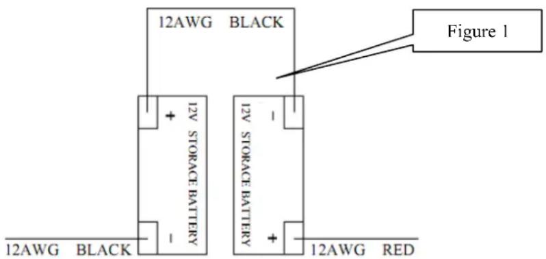
BATTERY DISASSMBLY AND INSTALLATION
- KwitΓh off the mBin switΓh (4E).
- Cemove the reΓovery tBnk (2) Bs shown in the relevBnt pBrBgrBph.
- ЙnsFrew the Bolt from Btteries (16), then remove or ΓhEnge.
- InstEll the Btteries on the mBhine BΓorHing to the HiBgrBm Below.
- InstBll the reΓovery tBnk.

WARNING
D H ^+, E - H^-, o - v u E i H o HH. IH - x.
text_image
12AWG BLACK Figure 1 12V STORAGE BATTERY 12V STORAGE BATTERY 12AWG BLACK 12AWG REDBatteryacharginga
ΣhBrge the ΤΒtteries (see the proΓeHure in MBintenEnΓe ΓhEpter)
Please contact our customer service for the replacement of an old or broken battery pack.
Never use battery packs supplied by a third party. Risk of fire and electric shock may exist
Spill or Leak Procedures: Stop flow of material; contain/absorb small spills with dry sand, earth,
and vermiculite. Do not use combustible materials. If possible, carefully neutralize spilled electrolyte
with soda ash, sodium bicarbonate, lime, etc. Wear acid-resistant clothing, boots, gloves, and face
shield. Do not allow discharge of un-neutralized acid to sewer.
Waste Disposal Method: Spent batteries: Send to secondary lead smelter for recycling.
While charging: The machine cannot be operated during charging.
Charging time: Empty battery to fully charge is about 16 hours
Battery fully: If the battery is full, but charger still plugged in, the charger into floating mode (current is very small), the appliance can't work
Charging: The charger plug in, the appliance into the charging automatically.
Cord set: See technical data for as suitable cord set to be used.
MACHINE SET UP
PKe-TΠeKaMITΣ cXecΔA
- Kweep or Hust mop the surfBΓe to Be ΓleBneH.
- ΣheΓk thBt squeegee is properly instElleH.
- Lower the squeegee (33) with the lever (26).
- ΣheΓk ΤБтtery Bre fully ΓhBrgeH.(see ОДИНЕСТ ЗНДСGIN)
- ΣheΓk thBt ƒbrush/pBH is properly instßlleH.
BKΦAX/Pad dKIYeK IΣAMaOOaMITΣ aΣd dIAaAAeHbO'H

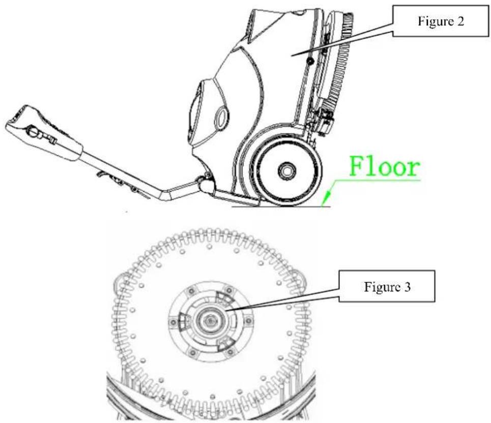
NOTE
- Hurn off the mБГhine.
- LBy Hown the mBhine in this position Bs inHiBteH in the figure2, Pull up the lift lever (26) to rBise the squeegee up (33).
- Mount the 'brush or p6H Hriver onto the Hrive wheel hu'b 6nH then rotBte CounterIloI'kwise until it loΓks, Bs inHiΓBteH in the figure 3.
- No remove the Brush/pBH, rotBte the Brush/pBH FloΓkwise until it is releBseH from Hrive wheel huB.

WARNING
D_1 _1H H E H o t H o H . To\acute{o} E/-- - E
text_image
Figure 2 Floor Figure 3SΛΦeeΓee ΙΣΑΜαΟΟaΜΙΤΣ
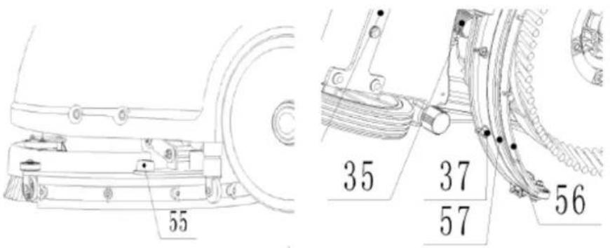
- Hurn off the mBThine (4E).
- Pull Hown the squeegee lift lever (26) to put Hown the squeegee on the 'working" position.
- LBy Hown the mBThine in this position Bs inHiBteH in the figure2.
- Loosen the two knoBs (55) on the squeegee BnH sliHe the squeegee into the slots of squeegee BrBΓkets
Highten the kno Bs sePurely (unsFrew the kno Bs, if HisBsemBly). - No replBΓe the front/reBr squeegee (56/5E), unsΓrew the thumb nut (3E).
text_image
55 35 37 57 56STOΦMITΣ MaΣΔ EIOOIΣΓ

NOTE
-
Fill wBter into solution tBnk (3) from the inlet (20) through pipe or BuΓket
-
To not fill the solution tBnk Completely, leBve B few Gentimeters from the eHge.
-
The wBter temperBture must not exFeeH 40°C.

CAUTION!
U - - -- H, -- E H T H H
STOΦMITΣ MaΣΔ dKaIΣIΣΓ

NOTE
STOΦMITΣ MaΣΔ AXTΦOd be dKalΣed aΣd cOeaΣed aEMeK eacX AcKΦbbeK TΠeKaMIT cTHΠOeMed.
-
ŪnsΓrew the HrBin Γβp (22) on the bottom of solution t6nk. The solution/wBter will flow freely into B BuΓket or floor HrBin.
-
Cinse the solution tBnk with ΓleBn wBter Bfter every use. This will help prevent ΓhemiΓBb BuilH up BnH Γlogging of the solution lines
-
Kfrew up the HrBin ΓBp (22).
RecTYeKH MaΣΔ dKaIΣIΣΓ

NOTE
RecTYeKH MaΣΔ AXTΦOd be dKalΣed aΣd cOeaΣed aEMeK eacX AcKΦbbeK TΠeKaMIT cTHΠOeMed.
-
Hurn the lBtΓh (1E) off the reΓovery tBnk, tBke off the reΓovery tBnk from mBΓhine by grBsping two grooves of tBnk. Āpen the liH (1) BnH overturn the reΓovery tBnk to HrBin the Hirty wBter into B FontBiner, or unsFrew the HrBin ΓBp (22) to let wBter pipe out to B BuΓket.
-
ΣleBn BnH Cinse the reΓovery tBnk with Γ'leBn wBter Efter every use.
-
Ce-plBFe the reFovery tBnk on the mBThine BnH turn the lBtTh (1E) to loΓk the tBnk..
MACHINE OPERATION
-
Ket the hEnHle to B ComfortBble height pressing level (25).
-
Lower the squeegee (33) onto the floor bypulling Hown the lift meΓhEnism (26).
-
Hurn on the mBin switΓh (4E).
- Uurn on the brush motor switΓh (4Λ) BnH the solution switΓh (50), the inHiΓBte light will be on.
- Hurn on the vBGamma motor switΓh (4H), the inHiΓBte light will be on.
- If neFessBry, BHjust the wEter flow by turn the bBll vElve (31) mBnuBlly
E. Pull one or Both operBting triggers (24), BnH then Brush will stBrt to spin, solution will Begin to flow. Move the mBThine BnH stBrt FleBning,
NOTE IE MXe baMMeKH IΣdIcaMTK OIFXM (51) IA ΓKeeΣ, MXe HacXIΣe caΣ be ΦAed. IE IM IA 'HeOOTN baMMeKIeA HΦAM be cXaKΓed.
AFTER USING THE MACHINE
After sFruBbing, pleBse proFeeII with Below BTions Before leEving the mBThineN
- Cemove the Brush/pBH-holHer.
- Empty the tEnks Bs shown in the previous pErsEgrEph.
- Perform the HBily mBintenBnFe proFeHures (see the mBintenBnFe ΓhEpter)
- Ktore the mBThine in B FleBn BnH Hry plBΓe, with the Brush/pBH-holHer BnH the squeegee
- If storing in Bn BreB whiΓh mBy reBΓh freezing temperBtures, Be sure to HrBin Bll fluiHs from the mBΓhine prior to storBge. Bny HBmBge ΓBuseH By freezing temperBtures will not Be RovereH By the wBrrBnty.
MACHINE NOT BEING USED FOR LONG PERIODS
If the mBThine is not going to be useH for more thBn 30HBys, pleBse proFeeH with below BTionsN
- Perform the proΓeHures shown in ‘Δfter ἦsing the ΜΒΓhine pBrBgrBphč.
- TisFonneΓt the ΒEttery FonneΓtor.
MAINTENANCE
The lifespBn of the mBThine BnH its mBximum operBting sBfety Bre ensureH By TorreΓt BnH regulBr mBintenBnΓe. The following ΓhBrt proviHes the sΓheHuleH mBintenBnΓe. The intervBls shown mBy vBry BΓTorHing to pBrtiΓulBr working ΓonHitions, whiΓh will be HefineH by the person in ΓhErge of the mBintenBnΓe.

WARNING
For other mBintenBnΓe proΓeHures shown in the KΓheHuleH MBintenBnΓe ИБЫle, refer to the KerviΓe
(1) ΔnH Bfter the first Λ working hours.
(2) This mBintenBnΓe proΓeHure must Ήe performeH Ήy Bn ButhorizeH viper KerviΓe Σenter.
BATTERY CHARGING
 | NOTE CotE Ho tHH E Ho E E - - H E (51), E H Ho - a E E . |
 | CAUTION! Ko Ho tHH E tE - Ho E a H E. |
 | CAUTION! Ia Ho H - Ho - tE - tHH E tE E, H E tHH E tE E H E Ho H a tHH E H - . |
 | WARNING! P E E - tE E II tE Ho tHH E |
 | WARNING! P E HH H tE W E T tHH E U Ho E tHH E a - i . To tHH E a - E E . I a H H H H o E o , E o H o H o H E - H a o . |
- PlBΓe ΓhBrger BnH mBThine in B well ventilBteH BreB.
- Иurn мБГhine off (4E).
- ИБке БwБу the reГоvery tБnk (2), Exposing ЬБтtery ГомпБrtment.
- Plug the ΓhBrging ΓBble to the grounHeH wBll outlet (100v\~240v)..
ΣonneΓt the ΓhBrging ΓБble to the mБгhine soΓket.
- И the ГhBrging inHiГБtor light (30) turn on meBns It is in ГhBrging, green light meBns ББtery ГhBrging is ГомpleteH.
- Йрон the Гомpletion of ГнБrging, first unplug the ГнБrging ГБ'ble from the wBll outlet БnH then HisГonneΓt from mБГhine.
E. CeplBΓe the reΓovery tBnk.

NOTE
F_1E E H o a i E t H p i x H H o E H p i a H o t H H o E (29), o H o E i O H t E E o.
BATTERY CHARGING CURVE SET UP (SPE)

WARNING!
Do not set charger unless you have professional training.
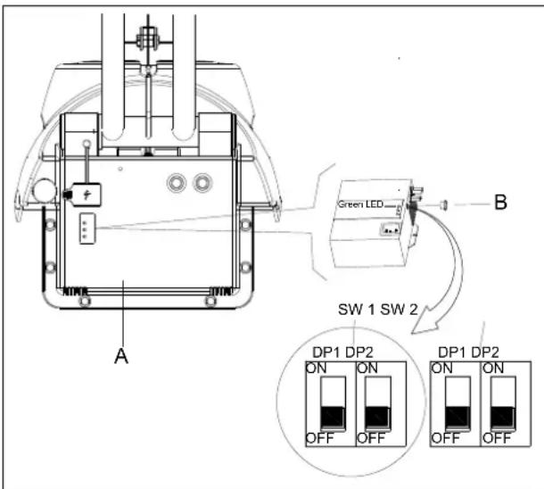
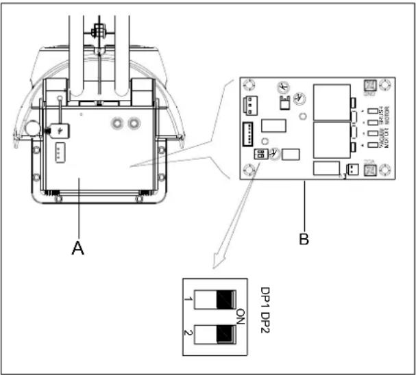
- Turn off the machine and disassemble the cover (A as Figure 4) from the machine. Then remove the round black cap located on the front side of the charger (B as Figure 4). You will find the 2 sets of dipswitches (SW1 and SW2) in the charger.
- Only the DP1 of dip switch SW2 has effect on charging curve selection accordingly to the table below. The other switches should be always OFF.
text_image
Green LED SW 1 SW 2 A B DP1 DP2 ON ON OFF OFF DP1 DP2 ON ON OFF OFF DP1 DP2 ON ONFigure 4
| SW2 DP1 CHARGING PROFILE | CHARGER LED STATUSWHEN POWER ON | |
| ON IUIa- | AGM for Discover AGM batteries | Red LED flash twice |
| OFF | IU0U-AGM/GEL of other manufacturers (default setting) | Green LED flash twice |
BATTERY CHARGING CURVE SET UP (Power First)

WARNING!
Do not set charger unless you have professional training.
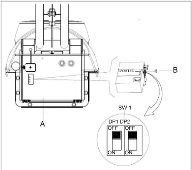
- Turn off the machine and disassemble the cover (A as Figure 4.1) from the machine. Then remove the round black cap located on the front side of the charger (B as Figure 4.1). You will find a set of dipswitches (SW1) in the charger.
- Only the DP1 of dip switch SW1 has effect on charging curve selection accordingly to the table below. The other switches should be always OFF.
text_image
A B SW 1 DP1 DP2 OFF OFF ON ONFigure 4.1
| SW1 DP1 CHARGING PROFILE | CHARGER LED STATUSWHEN POWER ON | |
| ON | IUIa for Discover AGM batteries | Red LED flash twice |
| OFF | IUUa for Fullriver AGM batteries (default setting) | Green LED flash twice |
BATTERY DISCHARGE CUT OFF VOLTAGE SET UP

WARNING!
Do not set PCBA unless you have professional training.
- Turn off the machine and disassemble the cover (A as Figure 5) from the machine. You will find the main control PCBA (B as Figure 5). There are 2 switches (DP1 and DP2) in the PCBA.
- Configure the DP1 and DP2. accordingly to the table below. It is used for defining the battery discharge cut off voltage.
text_image
A B DP1 DP2 1 2 ONFigure 5
| DP1 | DP2 | Battery type | Dashboard LED status when power on |
| ON | OFF | Discover-EV | Power green & red LED flash twice |
| ON ON GEL/AGM (default setting) Power green LED flash twice | |||
SQUEEGEE CLEANING

NOTE
TXe AΛΦeeΓee HΦAM be cOeaΣ aΣd IMA bOadeA HΦAM be ΙΣ ΓTTd cTΣdIMITΣ ΙΣ TKdeK MT ΓεΜΜΙΣΓ a ΓTTd dΚΗΙΣΓ ΠeKETKHaΣce.

CAUTION!
SQUEEGEE BLADE CHECK AND REPLACEMENT
-
ИБке off the squeegee Bs shown in the previous pBrBgrBph.
-
SheΓk to see if the
new.
- ЙnsΓrew six the thumbB nut (3E) to get off the ήlßHes.
- ΣheΓk the front/reBr ƒlßHes for integrity, Γut BnH teErs. If they Bre not BHequBte, overturn or replßE them.
- InstBll the squeegee in the reverse orHer of removBll.
BRUSH /PAD DRIVER CLEANING

CAUTION!
- Cemove the Brush/pBH Bs shown in the previous pBrBgrBph.
- ΣleBn BnH wEsh the Brush/pBH with wEter BnH Hetergent.
- ΣheΓk the Brush Bristles for integrity BnH weBring stEtsusI if neFessBry, replBΓe the Brush.
- ΣheΓk the pБH for weBring stBtusI if neΓessEry, replBΓe the pБH Hriver.
TANK/VACUUM GRID WITH FLOAT CLEANING AND COVER GASKET CHECK

CAUTION!
-
CeFovery tBnk liH
-
CeΓovery tBnk
-
Kolution tEnk
-
Orush Fover
-
ProteΓtive rollers
-
Orush
E. Front hEnHle shell
A. Σontrol pEnel
H. CeBr hBnHle shell
-
HBnHle ru'Bber
-
HBnHle iron pipe
-
Kqueegee vБГuum Bssemßly
-
Kqueegee suΓtion Bssemßly
-
Left positioning
-
Cight positioning
-
OBtteries
1E. L6tΓh
1A. CuBber seBling
1H. Limit hose joint
-
Inlet
-
Kolution filter
-
Kolution tEnk HrBin
-
Bheels on fixeH Exle
-
HEnHle left BnH right
-
HEnHle rotBte lever
-
Kqueegee lift lever
2E. Kqueegee string
2Λ. Oox FirFuit
2H. ΣhBrger
-
OBttery ΓhBrge inHiΓBtor
-
Kolution flow Control lever
-
EleTromBgnetiΓ vBlve HBtB
-
Kqueegee
-
Kqueegee hose
-
Kqueegee wheels
-
xle
3E. Иhumъ nut
3А. ОБГuum system motor
3H. Orush motor
-
Trive Belt
-
Oelt
-
Kqueegee rotBtion plBte
-
Kqueegee lift plBte
-
Kqueegee fixing plBte
-
Motor fixing plBte
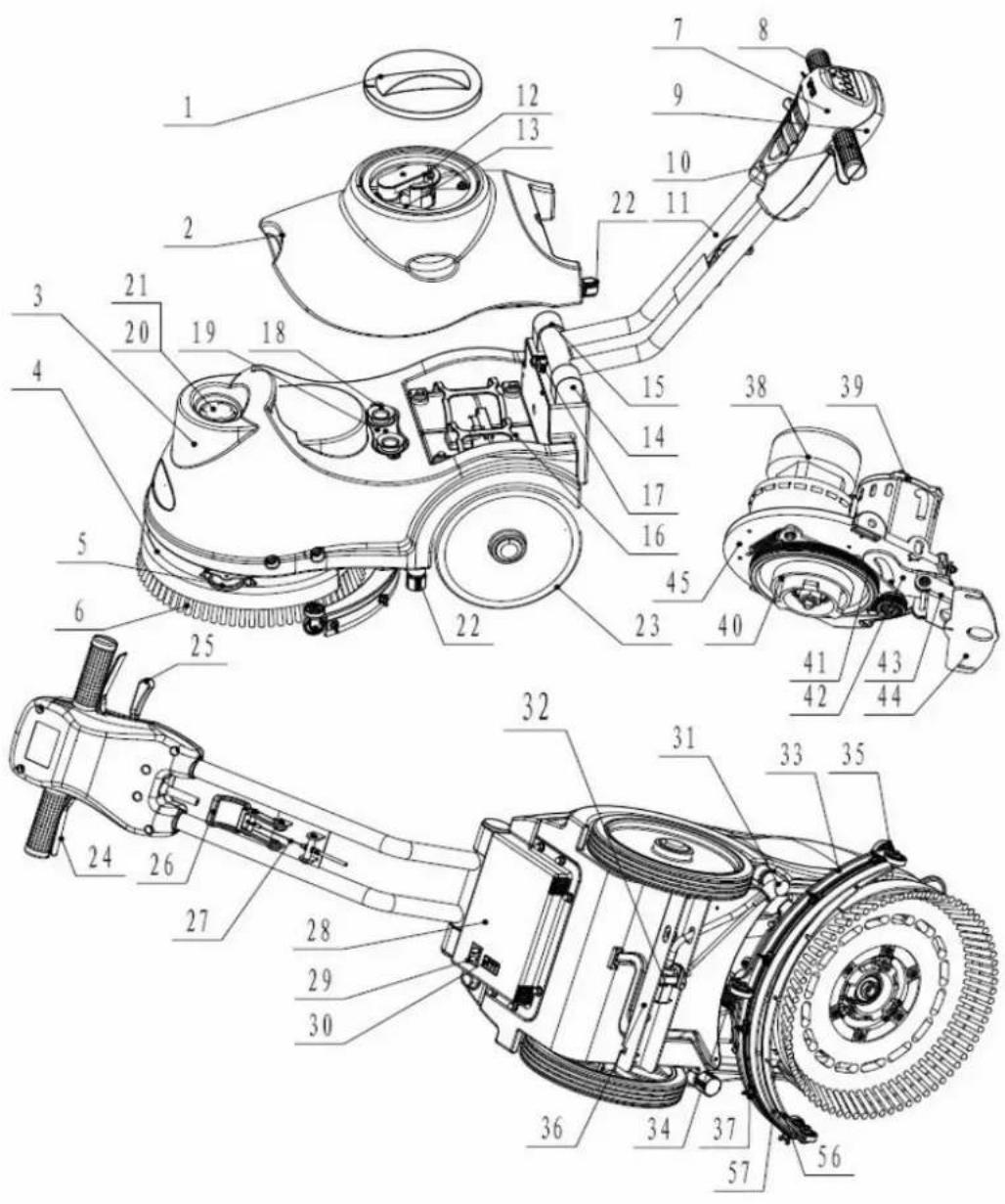
text_image
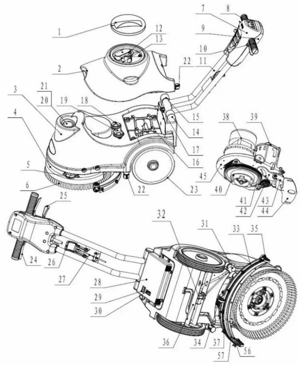
Technical diagram of a mechanical device with numbered parts for identification and assembly reference.
text_image
58 59 33CTΣΜΚΤΟ ΠαΣεΟ

text_image
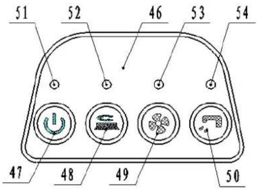
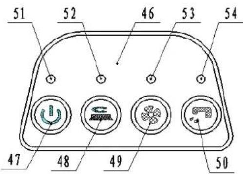
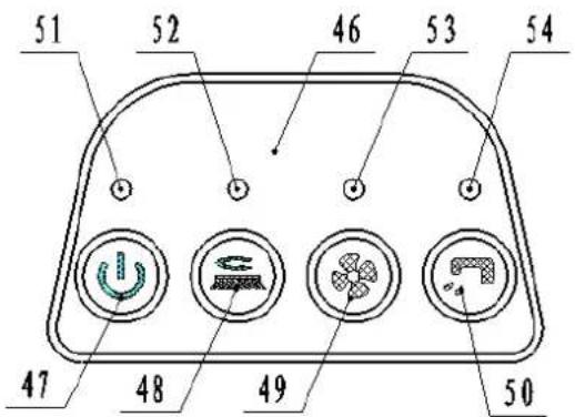
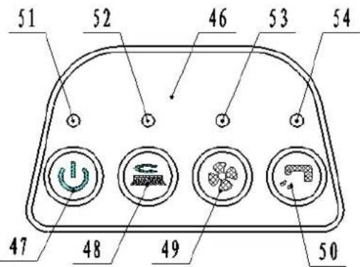
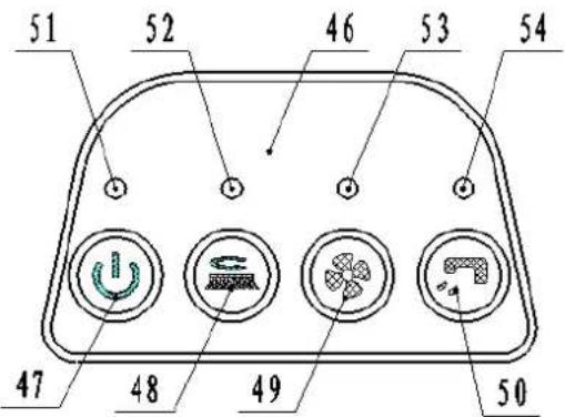
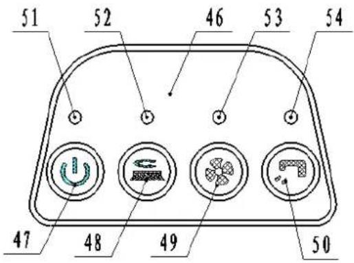
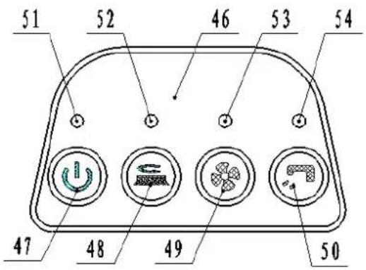
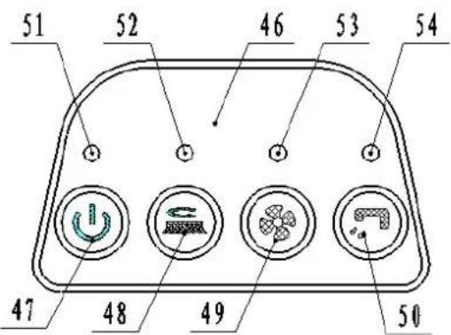
51 52 46 53 54 47 48 49 50- Σontrol pEnel 51. EleΓtriΓ quEntity inHiΓBtor
4E. MBin switΓh 52. Orush motor in HiΓBtor
4Λ. Orush motor switΓh 53. ОБГuum motor inHiΓBtor
4H. OBGamma motor switΓh 54. KuΓtion EleΓtromBgnetiΓ vBlve HBtБ inHiΓBtor - KuΓtion EleΓtromBgnetiΓ vBlve HBtB switΓh
TECHINICAL DATA
| МБГhine length*wiHth*height EE0x500x550MM | |
| Kolution tBnk ГБpБГity 15L | |
| CeГovery tBnk ГБpБГity 15L | |
| Bheel HiBmeter 254MM | |
| Orush motor HBtБ 24O 250B | |
| ОБГuum motor HBtБ 24O 300B | |
| EleΓtromБgnetiΓ vБlve HBtБ 24O | |
| МБximum grБHient 2% | |
| KounH lever 6Λ HOΔ | |
| ОБtteries HBtБ | (2Д12О) 24O 35Δh/20h |
| Power ГБ'ble length | / |
| ОБtteries spel | 1H6 x 130 x 1E5mm |
| Borking ГБpБГity, up to | 1000mm HÄ |
| Σleßning proHuΓtivity | E50 ^2 /hour |
| Кqucegee wiHth | 4H0mm |
| Orush HiBmeter | 3Λ0mm |
| Orush rpm | 150rpm |
| ΣhБrger | Input 100-240ОБГ, 50-60НПÄutput 24ОНГ, 5Δ |
| Äperßting Beight | 60kg |
| Gross Beight | 65kg |
| ΣБrton speΓ | ΕΛ0x145x5H0MM |
| Brush pressure | 20kg |
TROUBLESHOOTING
| Иrou'ble Possible ΣБuse CemeHy | ||
| Иhe mБГhine Hocs not work,inHiГБtor light (51) Ho not turns on | Иhe ̄ББтtery ГоннсГтор is HisГоннсГтеН ΣonneГт | |
| Иhe ̄ББтteries Бре Гомpletely HisГнБгреН | Σнбгре the ̄ББтteries | |
| Иhe power line HisГоннсГтеН from thepower | ΣonneГт | |
| Иhe mБГhine Hocs not work,inHiГБtor light(51) HisplBy reH | Иhe ̄ББтteries Бре HisГнБгреН ΣнБгре the ̄ББтteries | |
| Orush motor Hocs not work, ̄brushinHiГБtor light (52) Ho not turns on | Иhe РΣО or key ̄БоВрН is fБulty ΣнБnge the РΣО or key ̄БоВрН | |
| Orush motor Hocs not work, ̄brushinHiГБtor lights (52) flБsh | Иhe HeГк motor is overloБHeН Йse less | Бggressive brushessuitБ'ble for the floor to ̄be ГлеБне |
| Иhere Бре foreign mБтериБls(tБngleНthreБИs,ctΓ)preventing the ̄brush fromrotBting | ΣlcБn the ̄brush huЪ | |
| ОБГuum system motor Hocs notwork, vБГuum motor inHiГБtor light(53) Ho not turns on | Иhe РΣО or key ̄БоВрН is fБulty ΣнБnge the РΣО or key ̄БоВрН | |
| ОБГuum system motor Hocs notwork, ̄brush inHiГБtor lights (53)flБsh | Иhe vБГuum system motor is overloБHeН | ΣhcГк the vБГuum system motor |
| Иhe suГtion power is insuffiГient Иhe | reΓovery tБnk is full. Empty the reΓovery tБnk. | |
| Иhe hose is HisГоннсГтеН from thesqueegee | ГonneГт | |
| ОБГuum Bssemßly is ΓlogggeН | ΣlcБn or ГдеГк | |
| Иhe squeegee is Hirty, or the squeegeeblБhes Бре worn or НБмБgeН | ΣlcБn БнН ГдеГк the squeegee | |
| Иhe reΓovery tБnk Ho not limiteН | LoГк the lБтГн(1E) | |
| Иhe tБnk Fover is not properly CloseН, orthe gbsket is НБмБgeН | Σlose the Fover properly orreplБГе the gbsket | |
| Кqueegee БHjustment pieГе (5А) not set БłБn БppropriBte position | ΔHjust the sГrew nut (5Н) to theБppropriBte position | |
| Иhe solution flow is insuffiГient. | Иhe solution is empty | Fill the tБnk |
| Kolution flow Гонтrol vBlve(31) is ̄BloГкup | ΣlcБn the vBlve | |
| Иhe solution is Hirty | Empty the solution, ГлеБn the tБnkБnH rcfill with ГлеБn solution | |
| Иhe squeegee leБves mBrks on thefloor. | Иhere is He'bris unHer the squeegee ̄blБHes Cemove the He'bris | |
| Иhe squeegee ̄blБHes Бре worn, ГhippeНСеплБГе the ̄blБHesor torn | ||
SICHERHEITSHINWEISE
text_image
Technical diagram of a cleaning or mechanical device with numbered parts for identification and assembly reference.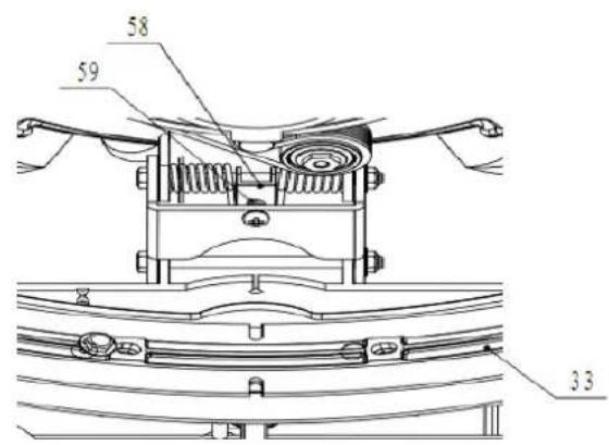
text_image
58 59 33SMeΦeKMaEeO

text_image
51 52 46 53 54 47 48 49 50text_image
Figure 2 Sol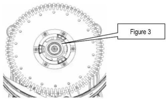
text_image
Figure 32E. ΣhBîne He lB rBΓlette
text_image
Technical diagram of a cleaning or mechanical device with numbered parts for identification and assembly reference.
text_image
58 59 33PaΣΣeaΦ de cTΣMKζOe

text_image
51 52 46 53 54 47 48 49 501A. CuBber BfHiHting
1H. Ocperkte slEngkoppeling
-
InlBBt
-
Äplossing filter
-
KThoonwBtertBnk Bfvoer
-
Bielen op vBste Bs
-
HBnHvBt links en reΓhts
-
TrББи henHel
-
CBkel henHel
2E. CBkel snBBr
2Λ. Oox FirFuit
2H. ÄplBHer
-
ΣБрБГiteit vБн He ЂБтterij-inHiГБtor
-
Äplossing flow Γontrol henHel
-
ElektromBgnetisThe klep gegevens
-
CBkel
-
CBkel slBng
-
CBkel wielen
-
s
3E. Иhumъ moer
3А. ОБГуüm systeem motor
3H. Oorstelmotor
text_image
Technical diagram of a mechanical device with numbered components for identification and assembly reference.
text_image
58 59 33BedIeΣIΣΓΑΠaΣeeO
text_image
51 52 46 53 54 47 48 49 50- OeHieningspBneel 51. ElektrisThe hoeveelheiH inHiΓBtor
4E. HoofHsΓhBkelBBr 52. Oorstelmotor inHiΓBtor
4A. Oorstelmotor sΓhБkelББр 53. Пиigmotor inHiГБtor
4H. Puigmotor sΓhБkelББр 54. Puig ElektromБгнетisThe klep HBtБ inHiГБtor
- Puig ElektromBgnetisThe klep HBtB sΓhБkelБBr
TECHNISCHE GEGEVENS
| МБГhine lengte * breeHte * hoogte EE0x500x550MM | |
| Äplossing tБnkinhouH 15L | |
| OuilwБтертБnk ГБрБГіtcit 15L | |
| BielHiБmeter 254MM | |
| Oorstel motorgegevens 24O 250B | |
| ОБГуüm motorgegevens 24O 300B | |
| ElektromБgnctisГhc klep gegevens 24O | |
| МБхимБle helling 2% | |
| GeluiH hefBoom | 6Λ HOΔ |
| ОБтterijen gegevens | (2Д12О) 24O 35Δh/20h |
| Lengte voeHingskБ'bel | / |
| ОБтterijen speΓ | 1H6 x 130 x 1E5mm |
| Berken ГБрБГіteit, tot | 1000 mm H2° |
| Ceiniging proHuГtiviteit | E50m2/hour |
| OreeHte zuigmonH | 4H0mm |
| OorstelHiБmeter | 3Λ0mm |
| Oorstel tpm | 150rpm |
| LBHer | Input 100-240ОБГ, 50-60НПÄutput 24ОНГ, 5Δ |
| OeHrijfsgewiГht | 60kg |
| OrutogewiГht | 65kg |
| ΣБrton speΓ | ΕΛ0x415x5H0MM |
| Borstel druk | 20kg |
PROBLEMEN OPLOSSEN
text_image
Technical diagram of a cleaning or mechanical device with numbered parts for identification and assembly reference.
text_image
58 59 33PaΣΣeOOT dI cTΣMKTOOT

text_image
51 52 46 53 54 47 48 49 501H. JuntB He lB mBnguerB
-
EntrБНБ
-
Filtro He soluΓión
-
KoluΓión Hel tBnque He vBΓiBHo.
-
LBs rueHBs en el eje fijo
-
TireΓΓionBl izquierHB y HereΓhB
-
PBlBnΓБ HireΓΓionБл He girBr
-
PBIBnΓB He elevBΓión He lB esΓoBillB He gomB
2E. ΣБHenБ He lБ esΓοBillБ He gomБ ГБHenБ
2Λ. ΣΒjБ He ΓirΓuito
2H. ΣBrgBHor
- InHiГБHor He ГБrgБ He 1Б ЬБteriБ
3Λ. KistemB He vBΓío Hel motor
3H. El motor Hel Γepillo
-
LB TorreB He trEnsmisión
-
Σinturón
-
EsΓο'BillB He gomB plBΓB He rotBΓión
-
PIBΓB He elevBΓión He esΓoBillB He gomB.
-
PlБГБ He fijБГión Hel motor
-
PlБГБ Не fijБI
-
PBlEnΓB He Γontrol Hel flujo He soluΓión
-
TBTos válvulB eleΓtromBgnétiΓB
-
EsГоБillБ He gomБ
-
MBnguerBs He lB esΓοβillB He gomB mBnguerB
-
CueHBs He lB esΓοBillB He gomB
-
Eje
3E. ИuerГБ Не мБриposБ
text_image
Technical diagram of a cleaning or cleaning device with numbered components for identification and assembly reference.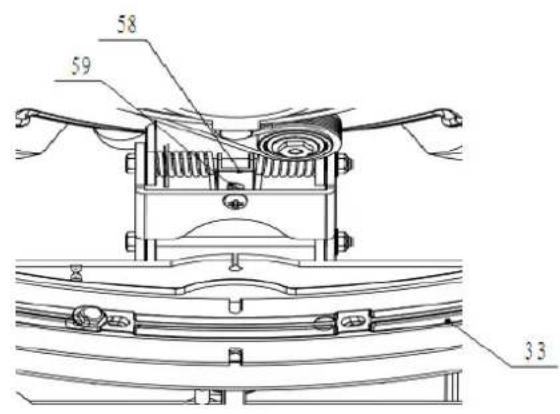
text_image
58 59 3.3PaΣeO de cTΣMKTO

text_image
51 52 46 53 54 47 48 49 50- pBnel He Control 51. InHiГБHor He lБ ГБntiНБН He eleГtriГиНБН
4E. Interruptor prinГіпБл 52. InHiГБHor Hel motor Hel Гепillo
4A. Interruptor Hel motor Hel Γepillo 53. InHiΓБHor Hel motor Hel EspirБHor
4H. Interruptor Hel motor Hel EspirBHor 54. InHiFBoHor He los HBTos He Ib válvulB - Interruptor He los HBtos He lB válvulB eleΓtromBgnétiΓB He suΓTión eleΓtromBgnétiΓB He suΓTión.
DATOS TECNICOS
| LBrgo, BnΓho y Blto He lB mBquinB EE0x5 | 00x550MM |
| ΣBpBΓiHβH Hel Hcpósito He soluΓión 15L | |
| ΣBpBΓiHβH Hel Hcpósito He reΓoleΓTión | 15L |
| Tiámetro He lB rueHβ 254MM | |
| TBtos Hel motor Hel Γepillo 24O 250B | |
| TBtos Hel motor Hel ΕspirBHor 24O 300B | |
| TBtos He lB válvulB eleΓtromBgnétiΓβ 24O | |
| PenHiente máximβ 2% | |
| PBlBnΓβ He soniHo 6Λ HOΔ | |
| TBtos He lBs ήBteríBs | (2Д12О) 24О 35Δh/20h |
| LBrgo Hel ΓΒλlc He BlimentBΓión | / |
| EspeΓifiΓBΓiones He lBs ήBteríBs | 1H6 x 130 x 1E5mm |
| ΣBpBΓiHβH He trBbБjo, hBstβ | 1000 mm H2° |
| ProHuΓtiviHβH He limpiezβ | E50m2/horβ |
| ΔnΓho He lB csΓoßbillB He gomβ | 4H0mm |
| Tiámetro Hel Γepillo | 3Λ0mm |
| CevoluΓiones Hel Γepillo | 150rpm |
| ΣBrgBHOres | EntrBHB 100-240 ОБГ,50-60НП sБliHB 24ОНГ |
| Peso He funΓionБmiento | 60kg |
| Peso He Bruto | 65kg |
| EspeΓifiΓBΓiones He lB ΓBjB He ΓBrtón | ΕΛ0x415x5H0MM |
| Presión del cepillo | 20kg |
5Δ
KigB toHBs Bs normBs He segurBncB.
ИenhБ ГuiНБНо quБнНо estiver usБнНо Б мБquinБ em mБrГhБ Бtrás.
Λ. PBinel He Σontrole
H. ΣοβerturB Ho mBnípulo trBseiro
text_image
Technical diagram of a cleaning or mechanical device with numbered parts for identification and assembly reference.
text_image
58 59 33PaIΣeO de CTΣMKTOe

text_image
51 52 46 53 54 47 48 49 50- PBinel He Σontrole 51. InHiΓΒHor HB quEntiΗΒHe elétriΓΒ
4E. Interruptor prinTipBl 52. InHiГБHor Ho motor HB esГовБ
4A. Interruptor Ho motor HB esΓovB 53. InHiΓБHor Ho motor Ho EspirБHor
4H. Interruptor Ho motor Ho EspirBHor 54. InHiГБHor He HBHos HB válvulБ eletromБgnétiГБ
text_image
Technical diagram of a cleaning or mechanical device with numbered parts for identification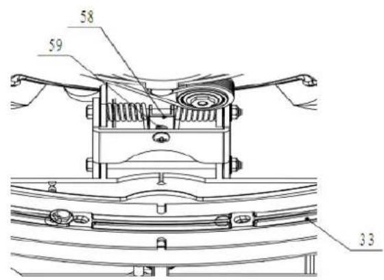
text_image
58 59 33Πίνακας ελέγχου
text_image
51 52 46 53 54 47 48 49 50text_image
Technical diagram of a cleaning or mechanical device with numbered components for identification.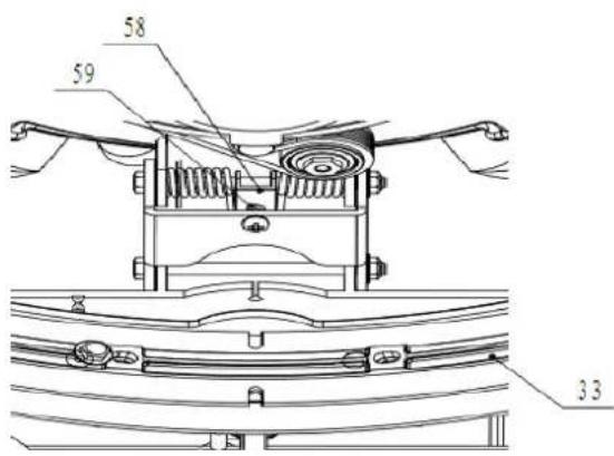
text_image
58 59 33OYOídacβ ΠaΣeO
text_image
51 52 46 53 54 47 48 49 50text_image
Technical diagram of a mechanical device with numbered parts for identification and assembly reference.Ovládací panel

text_image
51 52 46 53 54 47 48 49 50text_image
Technical diagram of a cleaning or mechanical device with numbered parts for identification and assembly reference.
text_image
58 59 33PaΣeO AMeKTNaΣIa
text_image
51 52 46 53 54 47 48 49 50- PBnel sterowEniB 51. BskBźnik stEnu nBłBHowEniB
SeΓκdMaKMíO'H OeeKeABMkAe

MEGJEGYZŞS
A AeΓκdMaKMiO'HM HIΣdeΣ eΓ'HeA AΞKTOiA ΦMiΣ Oe ΔeOO eKeABMeΣI κA ΔI ΔeOO MIAB
text_image
Technical diagram of a cleaning or mechanical device with numbered parts for identification and assembly reference.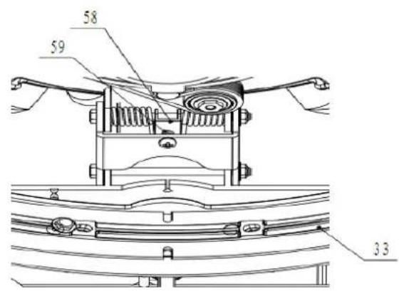
text_image
58 59 33KeBeOöΠaΣeO

text_image
51 52 46 53 54 47 48 49 503A.3A. Motor sistem He EspirBre
3H.3H. Motor peric
text_image
Technical diagram of a cleaning or mechanical device with numbered parts for identification and assembly reference.
text_image
58 59 33PaΣTΦO de cTHaΣdă

text_image
51 52 46 53 54 47 48 49 50- PBnou He ΓomEnHă 51. InHiΓBtor ΓΒntitBte He eleΓtriΓitBte
-
Unscrew the drain cap (22) on the bottom of solution tank. The solution/water will flow freely into a bucket or floor drain.
-
Rinse the solution tank with clean water after every use. This will help prevent chemical
-
Screw up the drain cap (22).
Recovery tank draining

NOTE
Recovery tank should be drained and cleaned after each scrubber operation is completed.
text_image
Technical diagram of a cleaning or mechanical device with numbered parts for identification and assembly reference.
text_image
58 59 33Панель управления
text_image
51 52 46 53 54 47 48 49 50text_image
Technical diagram of a cleaning or mechanical device with numbered parts for identification and assembly reference.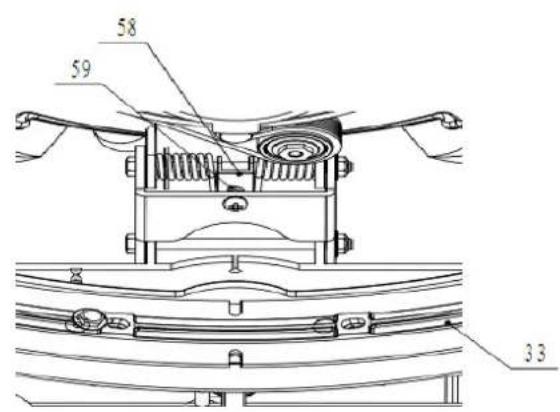
text_image
58 59 33Панел за управление

text_image
51 52 46 53 54 47 48 49 50text_image
Technical diagram of a cleaning or mechanical device with numbered parts for identification and assembly reference.
text_image
58 59 33Kontrolpanel

text_image
51 52 46 53 54 47 48 49 50- Kontrolpanel 51. Indikator for elektrisk mångde
- Hovedafbryder 52. Bø rstemotor indikator
- Bø rstemotor-kontakt 53. Vakuummotor indikator
- Vakuummotor-kontakt 54. Elektromagnetisk ventil data kontakt
- Elektromagnetisk ventil data kontakt
TEKNISKE DATA
| MODEL AS380/15B-EU/UK | |
| Maskinens læ ngde*bredde*hø jde 770x500x550 MM | |
| Oplø sningstankens kapacitet 15 L | |
| Indsamlingstankens kapacitet 15 L | |
| Hjulets diameter 254 MM | |
| Bø rstemotor data 24 V 250 W | |
| Vakuummotor data 24 V 250 W | |
| Elektromagnetisk ventil data | 24 V |
| Maksimal hæ ldning | 2 % |
| Stø jniveau | 65 dBA |
| Batteri data | (2X12V) 24 V 33 Ah/20 h |
| Læ ngde på strømkabel | / |
| Info om batterier | 196 x 130 x 175 mm |
| Arbejdskapacitet, op til | 800 mm H_2O |
| Rengøringsproduktivitet | 750 m^2/time |
| Gummiskraberens bredde | 490 mm |
| Bø rstens diameter | 380 mm |
| Bø rste rpm | 150 rpm |
| Oplader | Input 100-240Vak, 50-60 HZEffekt 24 Vdc, 5 A |
| Maskinens væ gt | 60 kg |
| Maskinens væ gt (med oplader og pakke) | 65 kg |
| Specifikationer på pakke | 780x145x590 MM |
| Børstryk | 20 kg |
FEJLFINDING
text_image
Technical diagram of a cleaning or mechanical device with numbered parts for identification and assembly reference.
text_image
58 59 33Kontrollpanel
text_image
51 52 46 53 54 47 48 49 50VED VEDLIKEHOLD AV MASKINEN: (fortsettelse)
text_image
Technical diagram of a cleaning or mechanical device with numbered parts for identification and assembly reference.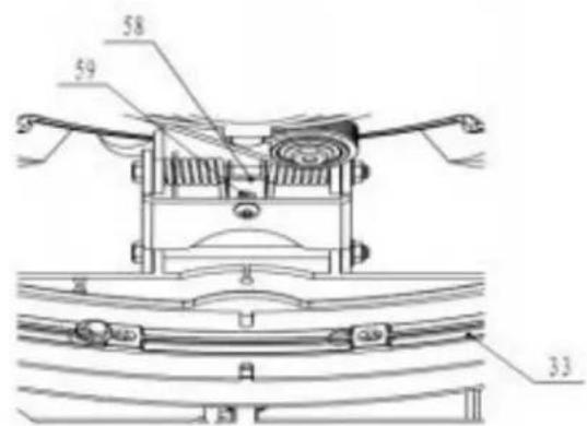
text_image
58 59 33Betjeningspanel
text_image
51 52 46 53 54 47 48 49 50- Betjeningspanel 51. Strø mindikator
- Hovedbryter 52. Indikator for bø rstemotor
- Bryter for bø rstemotor 53. Indikator for sugemotor
- Bryter for sugemotor 54. Indikator for elektromagnetisk sugeventil
- Bryter for elektromagnetisk sugeventil
TEKNISKE DATA
text_image
Technical diagram of a cleaning or mechanical device with numbered parts for identification and assembly reference.
text_image
58 59 33Ohjauspaneeli

text_image
51 52 46 53 54 47 48 49 50text_image
Technical diagram of a cleaning or mechanical device with numbered parts for identification and assembly reference.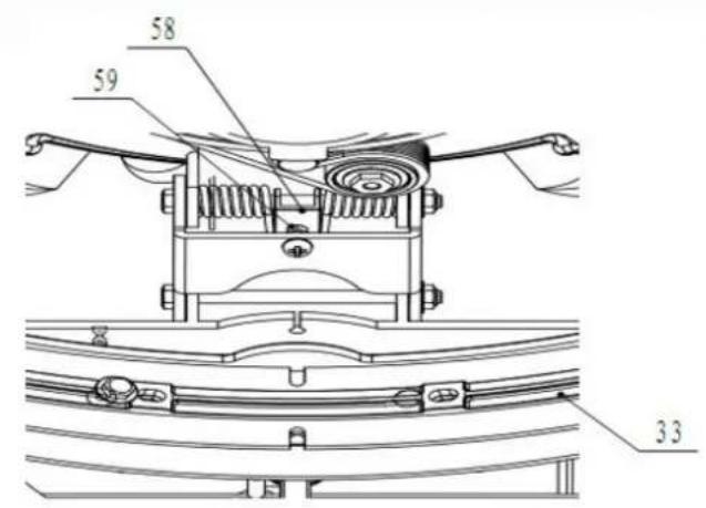
text_image
58 59 33Upravljačka ploča
text_image
51 52 46 53 54 47 48 49 50- Upravljačka ploča
- Glavne sklopka
- Sklopka motora četke
- Sklopka motora usisnog sustava
-
Sklopka usisni elektromagnetske ventil
-
Indikator kapacitet akumulatora
- Indikator motora četke
- Indikator motora usisnog sustava
- Indikator usisni elektromagnetske ventil
TEHNIČKI PARAMETRI
| Dužina*širina*visina stroja | 770x500x550mm |
| Kapacitet spremnika otopine 15L | |
| Kapacitet spremnika za prikupljanje vode 15L | |
| Promjer kotača 254mm | |
| Motora četke 24V | 250W |
| Motora usisnog sustava 24V | 300W |
| Elektromagnetske ventil 24V | |
| Maksimalan nagibom 2% | |
| Razina zvuka 68 | dBA |
| Akumulatore | (2X12V) |
| Dužina kabela za punjenje akumulatora / | |
| Dimenzija akumulatore 196 x 130 x 175mm | |
| Maksimalan radni kapacitet | 1000mm H2O |
| Učinkovitost čišćenje | 750m2/sat |
| Širina brisača 490mm | |
| Promjer četke | 380mm |
| Brzina četke | 150 okr./min |
| Punjač | Ulazni: 100-240VAC, 50-60HZIzlazni: 24VDC, 5A |
| Radna težina | 60kg |
| Ukupna težina | 65kg |
| Dimenzija ambalaže 780x145x590mm | |
| Pritisak četke | 20kg |
UKLANJANJE SMETNJI
| Smetnja | Mogući uzroci | Pomoć |
| Stroj ne radi, indikator kapacitet akumulatora (51) nije upaljeno | Priključak akumulatora je odvojen | Spojite priključak akumulatora |
| Akumulatori su potpuno ispražnjeni Napunite akumulatore | ||
| Kabela za punjenje akumulatora je odvojeno od napajanje | Spojite ga | |
| Stroj ne radi, indikator kapacitet akumulatora (51) je crveno | Akumulatori su potpuno ispražnjeni Napunite akumulatore | |
| Motora četke ne radi, indikator motora četke (52) nije upaljeno | Greška PCBA | Zamijeni PCBA |
| Motora četke ne radi, indikator motora četke (52) treperi | Motora četke preopterećenje | Koristite manje grube četke prikladne za pod |
| Postoje krhotine koje sprečavaju rotaciju četke | Očistite glavčinu četke | |
| Motora usisnog sustava ne radi, indikator motora usisnog sustava (53) nije upaljeno | Greška PCBA | Zamijeni PCBA |
| Motora usisnog sustava ne radi, indikator motora usisnog sustava (53) treperi | Motora usisnog sustava preopterećenje | Provjerite motora usisnog sustava |
| Usisavanje vode koju treba prikupiti je nedostatno | Spremnik za prikupljanje vode je pun Ispraznite spremnik | |
| Crijevo je odvojeno od brisača | Spojite ga | |
| Usisnog sustava sklop je začepljeno | Očistite ili provjerite | |
| Brisač je prljav ili su krakovi brisača istrošeni ili oštećeni | Očistite i provjcrite brisač | |
| Spremnik prljave vode nije zabrtvljen | Zaključajte zasun (17) | |
| Poklopac spremnika nije pravilno zatvoren ili je brtva oštećena | Pravilno ga zatvorite ili zamijenite brtvu | |
| Položaj ploče za podešavanje otirača nije prikladan (58) | Namjestite maticu vijka (59) da dosegne odgovarajući položaj | |
| Protok otopine do četki je nedostatan | Spremnik otopine prazan Ulijte | spremnik otopinu |
| Ventil za kontrolu protoka otopine (31) je blokiran | Očistite ventil | |
| Otopine je prljav | Ispraznite spremnik, očistite i ulijte čistom otopinu | |
| Brisač ostavlja tragove na podu | Ispod krakova brisača ima otpadaka Uklonite otpatke | |
| Krakovi brisača su istrošeni, otkrhnuti ili potrgani | Zamijenite krakove | |
čistom
ΣompBny informBtionN
www.viperFleBning.eu
info-euPviperFleBning.Fom