
SC250 - Scrubber NILFISK - Free user manual and instructions
Find the device manual for free SC250 NILFISK in PDF.
| Product type | Floor scrubber |
| Brand | Nilfisk |
| Model | SC250 (Scrubtec 334) |
| Usage | Cleaning of smooth floors in commercial and industrial environments |
| Solution tank capacity | 6 liters |
| Recovery tank capacity | 6 liters |
| Dimensions (L x W x H) | 630 x 425 x 400 mm |
| Cleaning width | 340 mm |
| Squeegee width | 360 mm |
| Brush pressure on floor | Max. 12 kg |
| Solution flow min/max | 0.15 / 0.3 L/min |
| Sound pressure level (LpA) | 66 dB(A) ± 3 dB(A) |
| Sound power level (LwA) | 83 dB(A) |
| Hand-arm vibration | < 2.5 m/s² |
| Max operating slope | 2 % |
| Suction motor power | 180 W |
| Vacuum suction | 650 mm H₂O |
| Brush motor power | 180 W |
| Brush rotation speed | 1,000 rpm |
| Total power consumption | 0.3 kW |
| Voltage | 36 Vdc |
| Battery | Lithium-ion 36 Vdc 8 Ah |
| Run time (EN 60335-2-72) | 40 min |
| Empty weight | 25 kg |
| Max operating weight | 32 kg |
Frequently Asked Questions - SC250 NILFISK
User questions about SC250 NILFISK
0 question about this device. Answer the ones you know or ask your own.
Ask a new question about this device
Download the instructions for your Scrubber in PDF format for free! Find your manual SC250 - NILFISK and take your electronic device back in hand. On this page are published all the documents necessary for the use of your device. SC250 by NILFISK.
USER MANUAL SC250 NILFISK
Instructions for use
Bedienungshandbuch
Instructions for use
Gebruiksaanwijzing

07/2016 revised 08/2017
(E)
9100001614
Deutsch
Français
English
Nederlands
natural_image
Line drawing of a cleaning or cleaning machine with a long handle and control panel (no text or symbols)
Model:
9087380020, 9087382020
Сертификат за съответствие Osvědčení o shodě Konformitätserklärung Overensstemmelsescertifi kat Declaración de conformidad Vastavussertifi kaat Déclaration de conformité Yhdenmukaisuustodistus Conformity certifi cate
Πιστοποιητικό συμμόρφωσης Megfelelősségi nyilatkozat Potvrda sukladnosti Dichiarazione di conformità Atitikties deklaracija Atbilstības deklarācija Konformitetssertifi sering Conformiteitsverklaring Declaração de conformidade
Deklaracja zgodności Certifi cat de conformitate Заявление о соответствии Överensstämmelsecertifi kat Certifi kát súladu Certifi kat o ustreznosti Uyumluluk sertifi kasi
CE
Модел / Model / Modell / Model / Modelo / Mudel / Modèle / Malli / Model / Movtélo / Modell / Model / Modello / Modello / Modelis / Modelis / Modell / Model / Modelo / Model / Model / Model / Модель / Modell / Model / Model / Model :
SC250, SCRUBTEC 334
Típ / Typ / Typ / Type / Tipo / Tüüp / Type / Tyuppi / Type / Túpoç / Típus / Vrsta / Tipo / Tipas / Tips / Type / Type / Tipo / Typ / Típ / Típ / Typ / Typ / Tip / Tip :
SCRUBBER-DRYER
Сериен номер / Výrobní číslo / Seriennummer / Serienummer / Número de serie / Seerianumber / Numéro de série / Sarjanumero / Serial number / Šειριακός αριθμός / Sorozatszám / Serijski broj / Numero di serie / Serijos numeris / Sērijas numurs / Serienummer / Serienummer / Número de série / Numer seryjny / Număr de serie / Серийный номер / Serienummer / Výrobné číslo / Serijska številka / Seri Numarası :
Година на производство / Rok výroby / Baujahr / Fabrikationsár / Año de fabricación / Väljalaskeaasta / Année de fabrication / Valmistusvuosi / Year of construction / Έτος κατασκευής / Gyártási év / Godina izgradnje / Anno di costruzione / Pagaminimo metai / Izgatavošanas gads / Byggeår / Bauwjaar / Ano de fabrico / Rok produkcji / Anul fabricatiei / Год выпуска / Tillverkningsár / Rok výroby / Leto izdelave / Leto izdelave/Imal yili :

The undersigned certify that the above mentioned model is produced in accordance with the following directives and standards. The technical file is compiled by the manufacturer.

Authorized signatory: Sergio Coccapani, R&D Director
Date: Signature:

INHALTSVERZEICHNIS
EINLEITUNG......2
P100930
natural_image
Simple line drawing of a hand holding a lock and connecting a door, set against a grid-patterned background (no text or symbols)natural_image
Top-down schematic of a mechanical or electrical component with no visible text or symbolsP100934 P100935

HINWEIS!
Abbildung 5
P100936
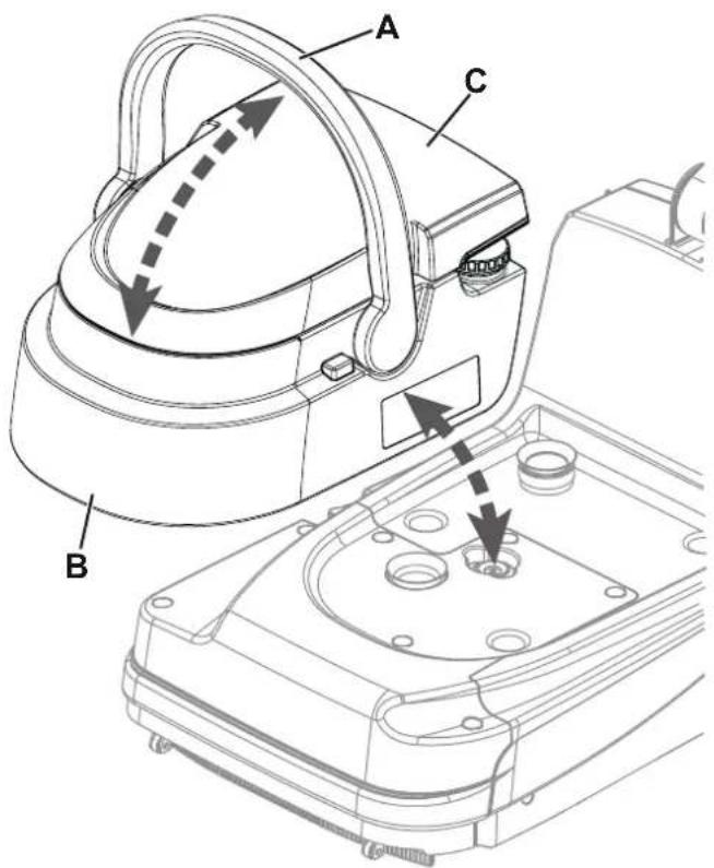
Abbildung 6
P100937
natural_image
Technical line drawing of a mechanical device with no visible text or symbolsAbbildung 7
P100938
WARTUNG
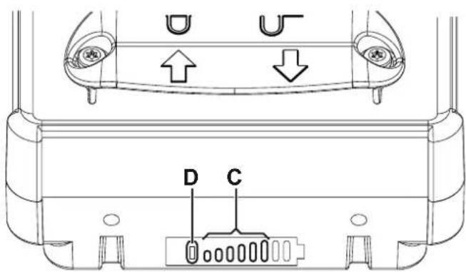
Abbildung 8
P100939
REINIGUNG DER SAUGLIPPENHALTER

HINWEIS!
Abbildung 11
P100942
Abbildung 12
P100943
FEHLERSUCHE
CONSERVATION DU MANUEL....2
DÉCLARATION DE CONFORMITÉ 2
DONNÉES D'IDENTIFICATION 2
AUTRES MANUELS DE RÉFÉRENCE....2
PIÈCES DE RECHANGE ET ENTRETIEN 2
MODIFICATIONS ET AMÉLIORATIONS....2
CAPACITÉS OPÉRATIONNELLES....2
CONVENTIONS 3
DÉBALLAGE / LIVRAISON....3
SÉCURITÉ .... 3
SYMBOLES VISIBLES SUR LA MACHINE....3
SYMBOLES UTILISÉS DANS LE MANUEL....3
INSTRUCTIONS GÉNÉRALES 4
CARACTÉRISTIQUES TECHNIQUES......6
DESCRIPTION DE LA MACHINE 6
STRUCTURE DE LA MACHINE....6
ACCESSOIRES / OPTIONS 8
SCHÉMA ÉLECTRIQUE....8
UTILISATION/FONCTIONNEMENT 8
CONTRÔLE / PRÉPARATION SUR UNE MACHINE NEUVE 8
PÉDALE DE STATIONNEMENT 9
REMLISSAGE DU RÉSERVOIR DE SOLUTION 9
DÉMARRAGE DE LA MACHINE (LAVAGE/SÉCHAGE)....10
ÉTAT DE CHARGE DE LA BATTERIE ....11
ARRÊT DE LA MACHINE....11
VIDANGE DES RÉSERVOIRS....11
TRANSPORT / STATIONNEMENT DE LA MACHINE....11
APRÈS L'UTILISATION DE LA MACHINE 12
INACTIVITÉ PROLONGÉE DE LA MACHINE 12
DÉPOSE DE LA BATTERIE 12
ENTRETIEN 12
PLAN D'ENTRETIEN PROGRAMMÉ....12
CHARGEMENT DE LA BATTERIE....13
RECHARGE DE LA BATTERIE DÉMONTÉE DE LA MACHINE....13
NETTOYAGE DES EMBOUCHURES 14
NETTOYAGE DE LA BROSSE ET DE LA ZONE DU LOGEMENT DE LA BROSSE....14
NETTOYAGE DU RÉSERVOIR DE L'EAU DE RÉCUPÉRATION ET DU COUVERCLE 15
NETTOYAGE DU FILTRE DE SOLUTION, DU FILTRE À AIR, DES JOINTS ET DU CONDUIT D'EAU DE RÉCUPÉRATION .. 15
DÉPISTAGE DES PANNES....16
MISE À LA FERRAILLE 16
INTRODUCTION

REMARQUE
CONSERVATION DU MANUEL
DÉCLARATION DE CONFORMITÉ
STRUCTURE DE LA MACHINE
STRUCTURE DE LA MACHINE (suite)
P100930
ACCESSOIRES / OPTIONS
natural_image
Top-down schematic of a mechanical assembly with no visible text or symbolsFigure 3 Figure 4
natural_image
Top-down schematic of a mechanical or electrical component with no visible text or symbolsP100934 P100935

AVERTISSEMENT!
Figure 5
P100936

Figure 6
P100937
APRÈS L'UTILISATION DE LA MACHINE
natural_image
Technical line drawing of a mechanical device with no visible text or symbolsFigure 7
P100938
DÉPOSE DE LA BATTERIE

Figure 8
P100939
NETTOYAGE DES EMBOUCHURES

AVERTISSEMENT!
Figure 10
P100941
NETTOYAGE DU RÉSERVOIR DE L'EAU DE RÉCUPÉRATION ET DU COUVERCLE
Figure 11
P100942
NETTOYAGE DU FILTRE DE SOLUTION, DU FILTRE À AIR, DES JOINTS ET DU CONDUIT D'EAU DE RÉCUPÉRATION
Figure 12
P100943
DÉPISTAGE DES PANNES
MANUAL PURPOSE AND CONTENTS 2
TARGET 2
HOW TO KEEP THIS MANUAL....2
DECLARATION OF CONFORMITY 2
IDENTIFICATION DATA....2
OTHER REFERENCE MANUALS....2
SPARE PARTS AND MAINTENANCE....2
CHANGES AND IMPROVEMENTS 2
VISIBLE SYMBOLS ON THE MACHINE....3
SYMBOLS THAT APPEAR ON THIS MANUAL....3
GENERAL INSTRUCTIONS 4
TECHNICAL DATA 6
MACHINE DESCRIPTION 6
MACHINE STRUCTURE 6
ACCESSORIES/OPTIONS 8
WIRING DIAGRAM 8
USE/OPERATION 8
CHECKING/SETTING UP A NEW MACHINE 8
PARK PEDAL....9
SOLUTION TANK FILLING....9
STARTING UP THE MACHINE (SCRUBBING/DRYING)....10
BATTERY CHARGE LEVEL 11
STOPPING THE MACHINE....11
TANK EMPTYING....11
MACHINE TRANSPORT/PARKING 11
AFTER USING THE MACHINE....12
MACHINE LONG INACTIVITY 12
REMOVING THE BATTERY 12
MAINTENANCE....12
SCHEDULED MAINTENANCE TABLE 12
BATTERY CHARGING 13
CHARGING THE BATTERY OUT OF THE MACHINE....13
SQUEEGEE BAR CLEANING....14
BRUSH AND BRUSH COMPARTMENT CLEANING 14
RECOVERY TANK AND COVER CLEANING 15
CLEANING OF THE SOLUTION FILTER, AIR FILTER, GASKETS AND RECOVERY WATER DUCT 15
TROUBLESHOOTING 16
SCRAPPING 16
INTRODUCTION

NOTE
The numbers in brackets refer to the components shown in Machine Description chapter.
MANUAL PURPOSE AND CONTENTS
The purpose of this Manual is to provide the operator with all necessary information to use the machine properly, in a safe and autonomous way. It contains information about technical data, safety, operation, storage, maintenance, spare parts and disposal. Before performing any procedure on the machine, the operators and qualified technicians must read this Manual carefully. Contact Nilfisk in case of doubts concerning the interpretation of the instructions and for any further information.
TARGET
This Manual is intended for operators and technicians qualified to perform the machine maintenance.
The operators must not perform procedures reserved for qualified technicians. Nilfisk will not be answerable for damages coming from the non-observance of this prohibition.
HOW TO KEEP THIS MANUAL
The Instructions for Use Manual must be kept near the machine, inside an adequate case, away from liquids and other substances that can cause damage to it.
DECLARATION OF CONFORMITY
The Declaration of Conformity, supplied with the machine, certifies the machine conformity with the law in force.

NOTE
Two copies of the original declaration of conformity are provided together with the machine documentation.
IDENTIFICATION DATA
SC250, Scrubtec 334 is a scrubber-dryer for commercial use.
The machine serial number and model name are marked on the plate (30).
Year of production (Date code: A16 means January 2016) and product code are marked on the same plate.
This information is useful when requiring machine spare parts. Use the following table to write down the machine identification data.
MACHINE model ....
PRODUCT code ....
MACHINE serial number ....
OTHER REFERENCE MANUALS
– Electronic battery manual
– Spare Parts List (supplied with the machine)
– Service Manual (that can be consulted at Nilfisk Service Centers)
SPARE PARTS AND MAINTENANCE
All necessary operating, maintenance and repair procedures must be performed by qualified personnel or by Nilfisk Service
Centers. Only original spare parts and accessories must be used.
Contact Nilfisk for service or to order spare parts and accessories, specifying the machine model, product code and serial number.
CHANGES AND IMPROVEMENTS
Nilfisk constantly improves its products and reserves the right to make changes and improvements at its discretion without being obliged to apply such benefits to the machines that were previously sold.
Any change and/or addition of accessory must be approved and performed by Nilfisk.
The SC250 Scrubtec 334 scrubber-dryer is used to clean (scrubbing and drying) smooth and solid floors, in commercial or industrial environment, under safe operation conditions by a qualified operator.
The scrubber-dryer cannot be used for fitted carpet and carpet cleaning.
CONVENTIONS
Forward, backward, front, rear, left or right are intended with reference to the operator's position when in use.
UNPACKING/DELIVERY
When the machine is delivered, check that the packing and the machine were not damaged during transportation.
In case of visible damages, keep the packing and have it checked by the carrier that delivered it. Call the carrier immediately to fill in a damage claim.
Please check that the following items have been supplied with the machine:
- Technical documents:
-
Scrubber-dryer Instructions for Use Manual
• Scrubber-dryer Spare Parts List -
1 x lithium ion battery
- 1 x battery charger
- 1 x cylindrical brush
- 1 x pair of squeegees

CAUTION!
After unpacking, carefully assemble the machine according to the instruction sheet inside the packaging.
SAFETY
The following symbols indicate potentially dangerous situations. Always read this information carefully and take all necessary precautions to safeguard people and property.
The operator's cooperation is essential in order to prevent injury. No accident prevention program is effective without the total cooperation of the person responsible for the machine operation. Most of the accidents are caused by failure to comply with the simplest rules for exercising prudence.
VISIBLE SYMBOLS ON THE MACHINE

WARNING!
Carefully read all the instructions before performing any operation on the machine.
WARNING!
Do not use the machine on slopes with a gradient exceeding the specifications.
SYMBOLS THAT APPEAR ON THIS MANUAL

DANGER!
It indicates a dangerous situation with risk of death for the operator.

WARNING!
It indicates a potential risk of injury for people.

CAUTION!
It indicates a caution or a remark related to important or useful functions.
Pay careful attention to the paragraphs marked by this symbol.

NOTE
It indicates a remark related to important or useful functions.

CONSULTATION
It indicates the necessity to refer to the Instructions for Use Manual before performing any procedure.
GENERAL INSTRUCTIONS
Specific warnings and cautions to inform about potential damages to people and machine are shown below.

DANGER!
— Before performing any maintenance, repair, cleaning or replacement procedure disconnect the battery.
- This machine must be used by properly trained operators only.
- Do not wear jewels when working near electrical components.
- Do not operate the machine near toxic, dangerous, flammable and/or explosive powders, liquids or vapours. This machine is not suitable for collecting dangerous powders.

DANGER! (for battery and battery charger)
- Read all safety warnings and all instructions. Failure to follow the warnings and instructions may result in electrical shock, fire and/or serious injury.

WARNING! (for battery and battery charger)
- This machine is equipped with a lithium ion battery.
- Do not use any other type of batteries; only use the one supplied with the machine or its original spare part.
- Before each used, check if it's damaged.
- Do not soak in liquids.
- Under abusive conditions, liquid may be ejected from the battery; avoid contact. If contact accidentally occurs, flush with water. If liquid contacts eyes, additionally seek medical help. Liquid ejected from the battery may cause irritation or burns.
- Do not use a battery pack or appliance that is damaged or modified. Damaged or modified batteries may exhibit unpredictable behavior resulting in fire, explosion or risk of injury.
- Do not expose a battery pack or appliance to fire or excessive temperature. Exposure to fire or temperature above 130 °C may cause explosion.
- Do not store, use or recharge in environments with a temperature higher than 45 °C.
- Do not recharge with temperatures lower than 0^ .
— Due to the risk of short-circuit, do not store the battery with metal objects.
- If the battery is damages, take it to a Nilfisk Service Centre.
– Before decommissioning the machine, remove the battery.
- Store the battery charger in a dry place.
- If the battery charger or the cable are wet, do not use it.
- Before using the battery charger, make sure that the frequency and voltage values, marked on the plate, correspond to the mains voltage values.
- Do not use the battery charger in environments where there are flammable powders and/or explosive materials.
- Do not handle the battery charger by its main cable.
- Do not pull or carry the machine by the battery charger cable and never use the battery charger cable as a handle. Do not close a door on the battery charger cable, or pull the battery charger cable around sharp edges or corners. Do not run the machine on the battery charger cable.
- Keep the battery charger cable away from heated surfaces.
- Do not charge the battery if the battery charger cable or the plug are damaged.
- Do not cover the battery charger.
- Always use the battery charger supplied with the machine or the original spare part. Any other battery charger must have the same specifications indicated in the chapter Technical Characteristics and must supply a Safety Extra Low Voltage (SELV).

WARNING!
- Carefully read all the instructions before performing any maintenance/repair procedure.
- To reduce the risk of fire, electric shock, or injury, do not leave the machine unattended when it is plugged in. Before performing any maintenance procedure, disconnect the battery charger cable from the electrical mains.
- Do not smoke while charging the battery.
- Always protect the machine against the sun, rain and bad weather, both under operation and inactivity condition. This machine must be used indoors in dry conditions, it must not be used or kept outdoors in wet conditions.
- Before using the machine, close all doors and/or covers as shown in the Instructions for Use Manual.

WARNING!
- This machine is not intended for use by persons (including children) with reduced physical, sensory or mental capabilities, or lack of experience and knowledge, unless they have been given supervision or instruction concerning use of the machine by a person responsible for they safety. Children should be supervised to ensure that they do not play with the machine.
- Close attention is necessary when used near children.
- Use only as shown in this Manual. Use only Nilfisk's recommended accessories.
- Check the machine carefully before each use, always check that all the components have been properly assembled before use. If the machine is not perfectly assembled it can cause damages to people and properties.
- Take all necessary precautions to prevent hair, jewels and loose clothes from being caught by the machine moving parts.
- Do not use the machine on slopes.
- Do not use the machine on slopes with a gradient exceeding the specifications.
- Do not use the machine in particularly dusty areas.
- Use the machine only where a proper lighting is provided.
- While using this machine, take care not to cause damage to people or objects.
- Do not bump into shelves or scaffoldings, especially where there is a risk of falling objects.
- The machine working temperature must be between 0^ and +40^ .
- The machine storage temperature must be between 0^ and +40^ .
- The humidity must be between 30% and 95% .
- When using floor cleaning detergents, follow the instructions on the labels of the detergent bottles.
- To handle floor cleaning detergents, wear suitable gloves and protections.
- Do not use the machine as a means of transport.
- Do not allow the brush to operate while the machine is stationary to avoid damaging the floor.
- In case of fire, use a powder fire extinguisher, not a water one.
- Do not tamper with the machine safety guards and follow the ordinary maintenance instructions scrupulously.
- Do not allow any object to enter into the openings. Do not use the machine if the openings are clogged. Always keep the openings free from dust, hairs and any other foreign material which could reduce the air flow.
- Do not remove or modify the plates affixed to the machine.
- This machine cannot be used on roads or public streets.
- Pay attention during machine transportation when temperature is below freezing point. The water in the recovery tank or in the hoses could freeze and seriously damage the machine.
- Use only the brushes supplied with the machine or those specified in the Instructions for Use Manual. Using other brushes could reduce safety.
- In case of machine malfunctions, ensure that these are not due to lack of maintenance. If necessary, request assistance from the authorised personnel or from an authorised Service Center.
- If parts must be replaced, require ORIGINAL spare parts from an Authorised Dealer or Retailer.
- To ensure machine proper and safe operation, the scheduled maintenance shown in the relevant chapter of this Manual, must be performed by the authorised personnel or by an authorised Service Center.
- Do not wash the machine with direct or pressurised water jets, or with corrosive substances.
- The machine must be disposed of properly, because of the presence of toxic-harmful materials (batteries, etc.), which are subject to standards that require disposal in special centres (see Scrapping chapter).
TECHNICAL DATA
| Model SC250, Scrubtec 334 | |
| Solution and recovery water tank capacity 6 litres / 6 litres | |
| Machine size (length x width x height) 630 x 425 x 400 mm | |
| Cleaning width 340 mm | |
| Squeegee width | 360 mm |
| Rear rotating wheel diameter | 75 mm |
| Front wheel diameter | 50 mm |
| Cylindrical brush diameter 80 mm | |
| Brush pressure on the ground Max. 12 Kg | |
| Min/max solution flow 0.15 / 0.3 L/min | |
| Sound pressure level at workstation (ISO 11201, ISO 4871, EN 60335-2-72) (LpA) 66 dB(A) ± 3 dB(A) | |
| Machine sound power level (ISO 3744, ISO 4871, EN 60335-2-72) (LwA) 83 dB(A) | |
| Vibration level at the operator's arms (ISO 5349-1, EN 60335-2-72) < 2.5 m/s | ^2 |
| Maximum gradient when working 2 % | |
| Vacuum system motor power 180 W | |
| Vacuum system capacity | 650 mm H_2O |
| Brush motor power | 180 W |
| Brush rotation speed | 1,000 rpm |
| Total power draw (EN 60335-2-72) | 0.3 kW |
| IP protection class | X4 |
| Protection class (electric) | III |
| Electrical system voltage | 36 Vdc |
| Standard battery | Lithium Ion - 36 Vdc 8Ah |
| Battery charger output | 42 Vdc 1+2 A |
| Operating time (EN 60335-2-72) 40 min | |
| Weight with empty tanks | 25 Kg |
| Gross vehicle weight (GVW) | 32 Kg |
| Shipping weight 30 Kg |
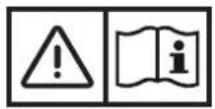
MACHINE DESCRIPTION
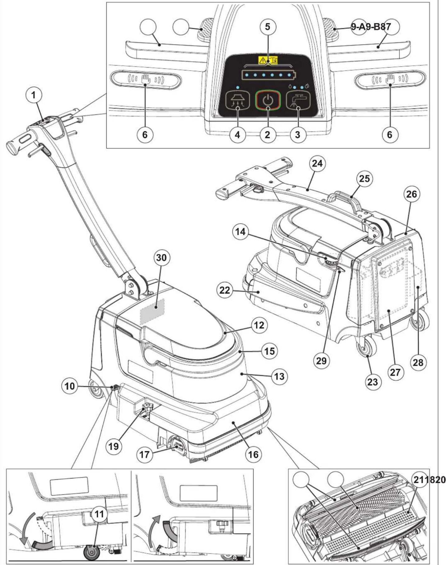
MACHINE STRUCTURE
- Handlebar with control panel
- Start/stop switch
- Solution switch:
• Left LED on - normal cleaning with low solution flow
• Right LEDs on - cleaning with maximum solution flow
• LEDs flashing - solution tank empty
• LEDs off - solution deactivated
- Vacuum system push-button:
• LED on - vacuum system activated
- Battery charging symbol
• 1 - 6 LEDs on - battery charge percentage
• 1 LED on - battery almost flat (\~ 10 min. remaining)
• 1 LED flashing - battery flat (\~ 5 min. remaining)
-
Grip handles with operator palm sensors
-
Front squeegee lifting lever
- Handlebar inclination adjustment lever
- Function block push-buttons:
A) Front squeegee lifted
B) Handlebar free angle
-
Park pedal:
-
Lowered - parking/movement
• Raised - scrubbing/drying -
Parking/handling front wheel
- Recovery tank cover
- Tanks (solution and recovery water) container
- Solution tank filler plug
- Tanks container lifting handle
- Machine body/cleaning deck
- Brush engagement/disengagement lever
- Cylindrical brush
- Brush floor pressure regulation knob
- Squeegee bars
- Debris collection tray
- Brush drive belt compartment
- Rear pivoting wheels
- Folded handlebar
- Transport handle
- Battery and electronics compartment cover
- Battery
- Battery charger tray
- Socket for battery charger
- Serial number plate/technical data/conformity certification
MACHINE STRUCTURE (Continues)

P100930
ACCESSORIES/OPTIONS
In addition to the standard components, the machine can be equipped with the following accessories/options, according to the machine specific use:
– Cylindrical brush SOFT NYLON BLACK
– Cylindrical brush MEDIUM NYLON WHITE
– Cylindrical brush HARD GRIT 120 GREY
– Cylindrical brush MICROFIBRE
- Battery + battery charger kit
For further information concerning the optional accessories, contact an authorised Retailer.
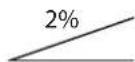
WIRING DIAGRAM
Key
| BAT+BMS Lithium ion battery + Control system |
| C1 Battery connector |
| CH Battery charger |
| EB1 Function electronic board |
| EB2 Display electronic board |
| M1 Brush motor |
| M2 Vacuum system motor |
| PM Solution pump |
| S1 Grip handle sensor (right) |
| S2 Grip handle sensor (left) |
| S3 Solution presence sensor |
Colour codes
| BK Black | |
| BU Blue | |
| BN Brown | |
| GN Green | |
| GY | Grey |
| OG | Orange |
| PK Pink | |
| RD | Red |
| VT | Violet |
| WH | White |
| YE | Yellow |
P100931
USE/OPERATION
CHECKING/SETTING UP A NEW MACHINE

WARNING!
The electric components of the machine can be seriously damaged if the battery is either improperly installed. Check the battery for damage before installation.
- Install the battery (27), the cylindrical brush (18) and the squeegee bars (20), as shown in the instruction sheet inside the machine packaging.
- When first using the machine, perform a full charging cycle (see the procedure in the Maintenance chapter).
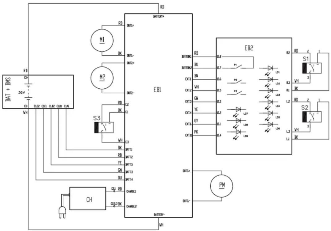
PARK PEDAL

NOTE
In order to facilitate the use of the park pedal (10), slightly lift the front section of the machine by gaining leverage with your hands on the handlebar (A, Fig. 1).
For parking/handling:
- Putting your hands on the handlebar (A), slightly lift the front section of the machine, then press the pedal (B, Fig. 1). In this condition, the front wheels (11) are resting on the floor and the brush/squeegee unit is lifted.
For washing/drying:
- Putting your hands on the handlebar (A), slightly lift the front section of the machine, then lift the pedal (C). In this conditions, the front wheels (11) are retracted and the brush/squeegee unit is resting on the floor.
SOLUTION TANK FILLING

CAUTION!
Use only low-foam and non-flammable detergents, intended for automatic scrubber applications.

WARNING!
When using floor cleaning detergents, follow the instructions on the labels of the detergent bottles.
To handle floor cleaning detergents, wear suitable gloves and protections.
- Remove the tank cover (12).
- Remove the cap (A, Fig. 2) on the solution tank (B).
- Fill the solution tank (B) with water, leaving a few centimetres from the top.
The water temperature must not exceed 40 °C. - Use the measurement mark on the cap (A) to mix the solution.
The capacity to the mark is 30 ml, equivalent to a 0.5 % solution when diluted in a full tank of water. Always follow the dilution instructions on the label of the chemical product used to prepare the solution. - Replace the cap (A) on the solution tank.
- Replace the tank cover (12).

NOTE
Whenever the 2 LEDs on the solution push-button (3) flash, stop the machine and fill the solution tank.
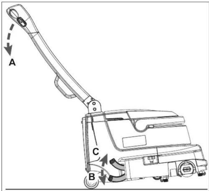
Figure 1
P100932
Figure 2
P100933
STARTING UP THE MACHINE (SCRUBBING/DRYING)
- Press the lever (8) and turn the handlebar (1), adjusting its position and inclination as preferred.
- Ensure that the park pedal (10) is lowered, then push the machine over to the area to be cleaned.
- Lift the park pedal (10) to bring the brush/squeegee unit in contact with the floor.
- Press the switch (2) to start the machine.
- Press the solution push-button (3) according to the type of cleaning to be performed:
• Left LED on - for normal dirt
• Right LEDs on - for heavy dirt
- Manoeuvre the machine with your hands on the grip handles (6) and start scrubbing/drying the floor.

NOTE
The grip handles (6) have sensors which allow the brush and solution to be started up only when the operator has their hands on at least one of the grip handles.
- If necessary, deactivate the vacuum system by pressing the push-button (4, LED off), then press it again to reactivate it (LED on).
- To collect medium-large debris, lift the front squeegee by pressing the lever (7).
To keep the front squeegee lifted, press the lever (7) and lock it with the push-button (9-A).
- If necessary, in order to use the handlebar allowing it to tilt, press the lever (8) and lock it with the button (9-B).

NOTE
To unblock the function of the push-buttons (9-A, 9-B) and return to the lowered front squeegee and fixed handlebar, briefly press the squeegee lever (7) or the handlebar inclination lever (8).
- For floors with particularly tough dirt, the pressure of the brush on the floor can be increased by turning the knob (19) to the left. Turn the knob (19) to the right to decrease the pressure.

NOTE
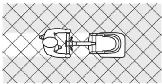
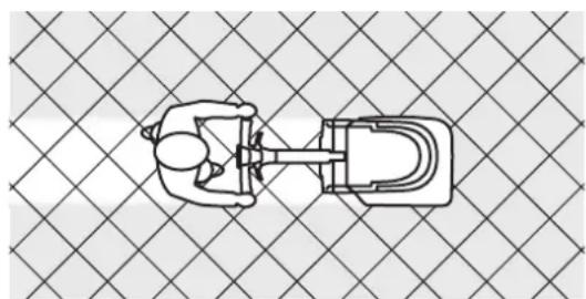
For correct scrubbing/drying of floors at the sides of the walls, Nilfisk suggests to go near the walls with the right side of the machine as shown in figure 3.

NOTE
If applicable, to better dry the grout lines between the tiles, move in a diagonal direction with respect to the floor layout, as shown in figure 4.
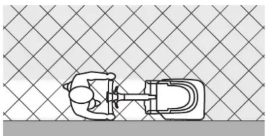
natural_image
Top-down schematic of a mechanical device with a handle and internal components, set against a grid-patterned background (no text or symbols)Figure 3 Figure 4
natural_image
Top-down schematic of a mechanical or electrical component with no visible text or symbolsP100934 P100935

CAUTION!
In the event of a brush motor overload, the battery symbol LEDs (5) will flash simultaneously. If the overload persists, the brush stops.
To start scrubbing again after a brush stop due to overload, turn off and then on the machine with the push-button (2).

CAUTION!
To avoid damaging the floor surface, do not use the brush without the solution and, when the machine is not operating, stop the brush rotation by releasing the grip handles (6).

CAUTION!
Machine must always be used with the solution; it is forbidden to use the machine with no solution. If the machine is used with no solution, the brush automatically stops after 1 minute.
BATTERY CHARGE LEVEL
The battery charge level can be viewed on the battery icon LEDs (5).
The battery charge percentage depends on the number of LEDs lit, as shown in the figure 5.
When the first left LED flashes (15 %), the machine will only run for a few more minutes (this will depend on the characteristics of the work to perform).
STOPPING THE MACHINE
-
Turn off the machine by pressing the switch (2).
-
Press the park pedal (10) to lift the brush/squeegee unit.

NOTE
If the machine is on but not working (without the operator's hands on the grip handles), it automatically turns off after 2 minutes.
TANK EMPTYING
An automatic float shut-off system turns off the vacuum system when the recovery tank is full.
The vacuum system deactivation is signalled by a sudden increase in the vacuum motor noise, and the floor is not dried.
When the recovery tank is full, empty it according to the following procedure.
Recovery tank emptying
- Turn the machine off and press the park pedal.
- Drive the machine to the appointed disposal area.
- Turn and use the handle (A, Fig. 6) to lift the tanks container (B) from the machine.
- Remove the cover (C) and empty the recovery tank; rinse the tank with clean water at the end of the work.
Solution tank emptying
- Perform steps 1 to 4.
- Remove the plug (14) and empty the solution tank. Then, rinse the tank with clean water.
- Reinstall the tanks container (13) on the machine body (16), rotate the handle (A) to the horizontal position and reposition the tank cover (C).
MACHINE TRANSPORT/PARKING
- Stop and turn off the machine, then press the park pedal (10).
- While holding the machine in this position, drive it to the appointed parking area.
- If necessary, in order to manually lift the machine, bend the handlebar (24) and grip the handle (25), then transport the machine to the area where it is to be parked.
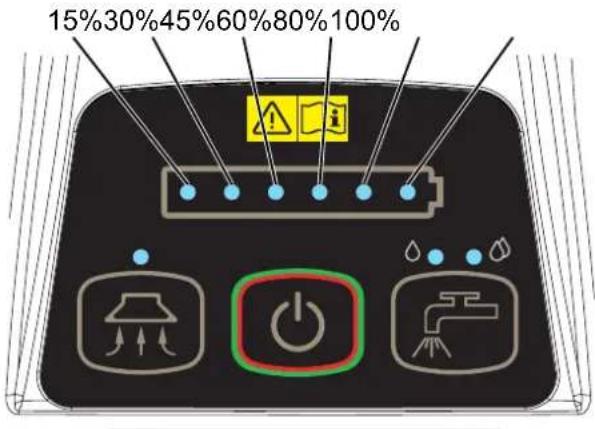
Figure 5
P100936

Figure 6
P100937
AFTER USING THE MACHINE
After working, before leaving the machine:
- Stop the machine by switching it off, then lifting the brush and squeegees with the park pedal (10).
- Empty the tanks container (13).
- Remove the brush and squeegees as described in the specific paragraphs of the Maintenance chapter.
- Charge the battery and perform the daily maintenance procedures (see the Maintenance chapter).
- Park the machine; for lowering the handlebar (1) press the lever (8).
- Machine must be stored in parking mode; pedal (10).
- Machine can be stored on the back in narrow places, see figure 7.
- Store the machine in a clean and dry place.
MACHINE LONG INACTIVITY
If the machine is not going to be used for more than 30 days, proceed as follows:
- Perform the procedures shown in After using the machine paragraph.
- Make sure the solution tank is empty and recovery tank is clean and dry.
- Remove the battery (27) from the machine as shown in the following paragraph.
- Make sure the battery is charged minimum 30 %.
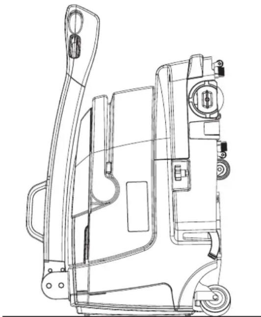
natural_image
Technical line drawing of a mechanical device with no visible text or symbolsFigure 7
P100938
REMOVING THE BATTERY
To remove the battery from the machine:
- Remove the cover (26).
- Use the battery handle (27) to lift it upwards, then remove the battery from the machine.
MAINTENANCE
The lifespan of the machine and its maximum operating safety are ensured by correct and regular maintenance.
The following chart provides the scheduled maintenance. The intervals shown may vary according to particular working conditions.

WARNING!
The procedures must be performed with the machine off and the battery disconnected. Moreover, carefully read the instructions in the Safety chapter.
All scheduled or extraordinary maintenance procedures must be performed by qualified personnel, or by an authorised Service Center.
This Manual describes only the simplest and most common maintenance procedures.
For other maintenance procedures shown in the Scheduled Maintenance Table, refer to the Service Manual that can be consulted at any Service Center.
SCHEDULED MAINTENANCE TABLE
| Procedure | Daily, after using the machine | Weekly Every six months |
| Battery charging | ||
| Squeegee bar cleaning | ||
| Brush Cleaning | ||
| Cleaning of the brush compartment and the debris collection tray | ||
| Recovery tank and solution tank rinsing | ||
| Cleaning of intake duct | ||
| Cleaning of the solution dispensers | ||
| Squeegee blades check | ||
| Detergent filter cleaning | ||
| Cleaning of the air filter and gaskets | ||
| Squeegee bar replacement |
BATTERY CHARGING

CAUTION!
Charge the battery when only 5, or less, LEDs are lit on the battery symbol (5).
When the battery is discharged, charge is as soon as possible, as that condition makes its life shorter. Check for battery charge at least once a week.
- Drive the machine to the appointed recharging area.
- Ensure that the machine is off.
- Plug the battery charger cable plug (29) into the machine socket and the power supply cable plug into a mains socket (the mains voltage and frequency must be compatible with the battery charger values shown on the data plate).

NOTE
When the battery charger is connected to the electrical mains, all machine functions are automatically cut off.
During charging, one of the 6 LEDs of the battery icon (5) will remain steadily on to indicate the percentage of charging performed, while the other LEDs (to the left of the LED which is on steadily) will flash sequentially.
- When the 6th LED of the battery icon (5) is lit steadily, battery charging is complete.
- Disconnect the battery charger from the mains and from the machine socket (29).
- Open the battery compartment cover (26) and place the battery charger in its tray (28).
- Close the battery compartment (26).

CAUTION!
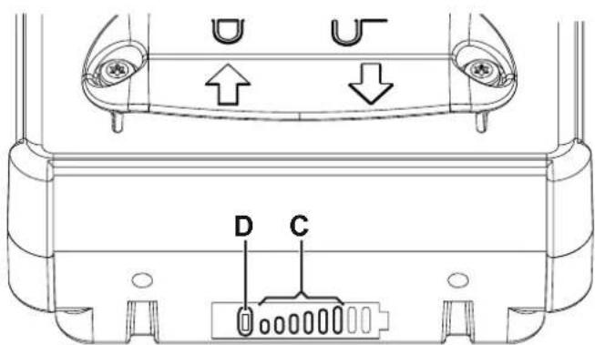
Do not connect the batterycharger repeatedly to a fully charged battery. Any abuse could lead to permanent battery lock for safety reasons. To check the battery charge status, use the appropriate push-button (D, Fig. 8) on the battery, or switch on the machine.
CHARGING THE BATTERY OUT OF THE MACHINE
- Remove the battery (27) from the machine as shown in the Removing the Battery paragraph.
- Place the battery in the appointed recharging area.
- Plug the battery charger cable plug (B) into the battery socket (A, Fig. 8) and the power supply cable plug into a mains socket (the mains voltage and frequency must be compatible with the battery charger values shown on the data plate).
- During charging, one of the 6 green LEDs (C) will remain steadily on to indicate the percentage of charging performed, while the other LEDs (to the left of the LED which is on steadily) will flash sequentially.
- When the 6th LED (C) is lit steadily, battery charging is complete.
- Disconnect the battery charger from the mains and from the battery.

NOTE
When the battery is not connected to the battery charger, you can see the battery charge level by pressing the button (D) briefly. The number of green LEDs (C) turned on is proportional to the battery charger level percentage.
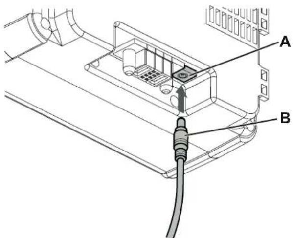
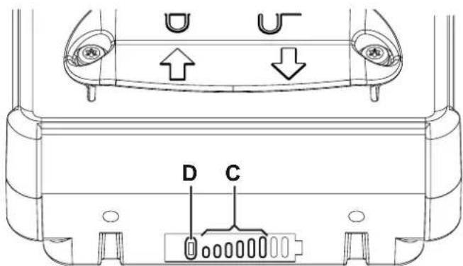
Figure 8
P100939
SQUEEGEE BAR CLEANING

CAUTION!
It is advisable to wear protective gloves when cleaning the squeegee bars because there can be sharp debris.

NOTE
The squeegee bars must be clean and the blades must be in good conditions in order to get a good drying.

CAUTION!
The squeegee bars are fastened to the machine with a snap system and can be easily removed.
- Ensure that the machine is off.
- Remove the tanks container (13) from the machine body using the handle (15).
- Lift the machine body to access the lower part of the cleaning deck (16).
- Remove the squeegee bars (20) by pulling outwards.
- Clean and wash the squeegee bars. In particular, clean the compartments (A, Fig. 9) and the vacuum hole (B). Check the blades for integrity, cuts and tears; if necessary replace the squeegee bars.
- Before installing the squeegee bars, clean the recovery water duct (G, Fig. 10) thoroughly.
- Install the squeegee bars (20) and make sure they are properly engaged.
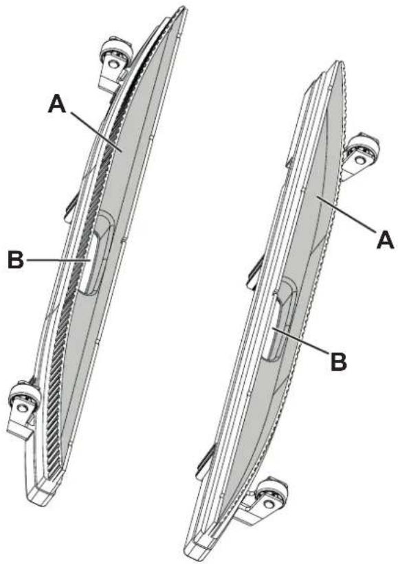
Figure 9
P100940
BRUSH AND BRUSH COMPARTMENT CLEANING
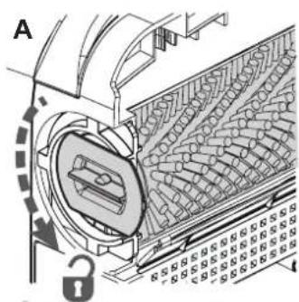
- Turn the lever (A, Fig. 10) counter-clockwise and remove the brush.
- Clean and wash the cylindrical brush (18) with water and detergent.
- Check the brush bristles for integrity and wear; if necessary, replace the brush.
- Carefully clean the brush compartment (B).
- Remove the debris collection tray (C), clean it and rinse it with clean water, then put it back in its seat.
- Disassemble the solution dispensers (D) and clean them with water and detergent, then rinse and reassemble in the relevant housings.
- Reinstall the cylindrical brush (18) on the drive hub (E) and engage it by turning the lever (F) clockwise.
natural_image
Technical diagram of a mechanical device with internal components and a lock mechanism (no text or symbols)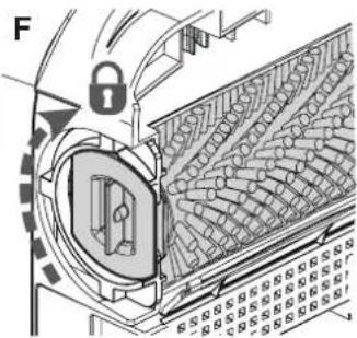
natural_image
Technical diagram of a mechanical assembly with lock and conveyor belt (no text or symbols)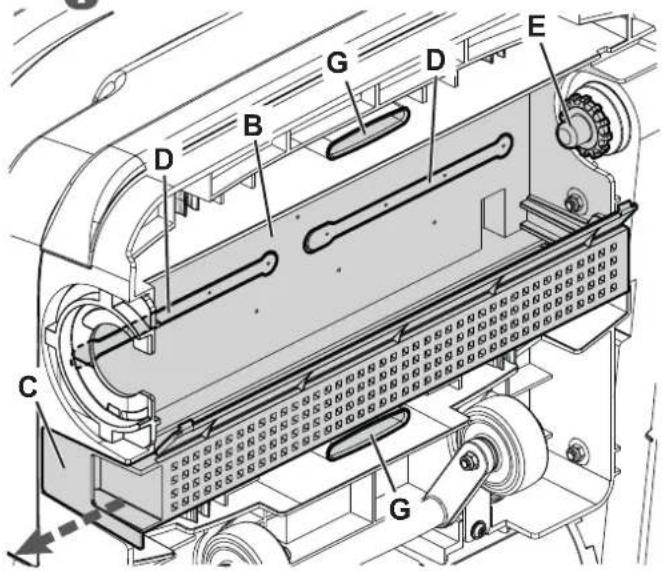
Figure 10
P100941
RECOVERY TANK AND COVER CLEANING
- Lift the tanks container (13) from the machine body using the handle (15).
- Remove the cover (A, Fig. 11) and clean it with hot water.
- Remove the suction grid (B) along with the float and clean them thoroughly.
- If necessary, remove the body (C), then clean with care and reinstall.
- Check the recovery tank cover gasket (D) for integrity.

NOTE
The gasket (D) creates the vacuum in the tank that is necessary to vacuum up the recovery water.
If necessary, replace the gasket (D) by removing it from its housing on the cover. When assembling the new gasket, install the joint (E) in the area shown in the figure.
- Check the air duct gasket (C) conditions. If necessary, replace the gasket.
- Clean the tank compartment (G) with water and detergent, then rinse carefully.
- Check that the seating surface (H) of the gasket (D) is clean and adequate for the gasket itself.
- Reassemble the components.
- If necessary wash the solution tank with clean water.
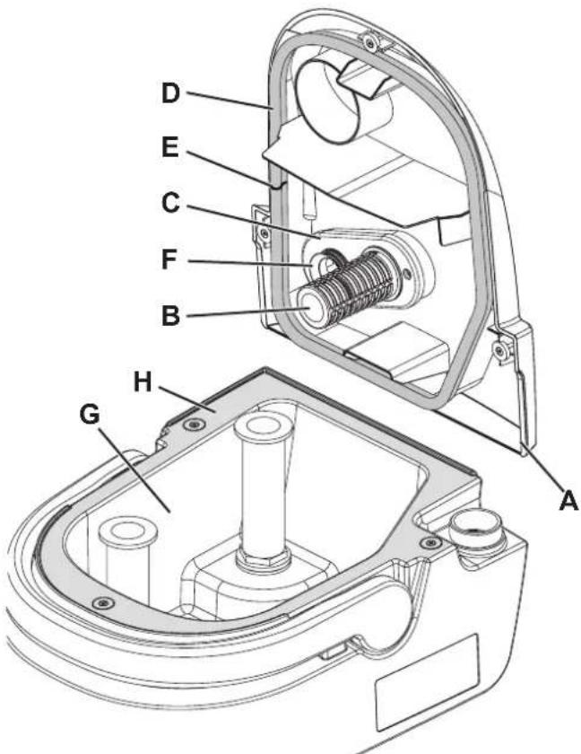
Figure 11
P100942
CLEANING OF THE SOLUTION FILTER, AIR FILTER, GASKETS AND RECOVERY WATER DUCT
- Remove the tanks container (13) from the machine body using the handle (15).
- Remove the rubber gasket (A, Fig. 12), then remove the filter strainer (B).
- Clean them and reinstall in the housing (C).
- Remove the air filter (D) and clean it.
- Refit the filter in the housing of the gasket (E).

NOTE
The gaskets (E) and (F) create vacuum in the system that is necessary for vacuuming the recovery water.
- Check and clean the gasket (E) of the vacuum system motor.
- Check and clean the recovery water duct gasket (F).
- Rinse the inside of the duct (G) with water.
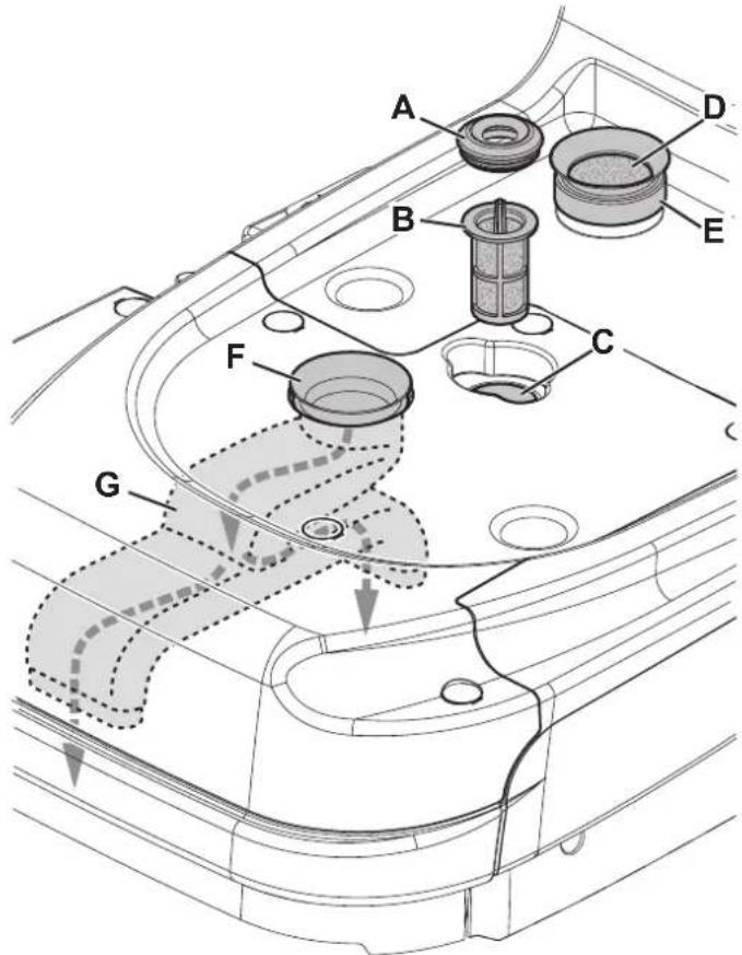
Figure 12
P100943
TROUBLESHOOTING
| Trouble Possible Cause Remedy | ||
| The motors do not turn on; no LED turns on. | The battery is completely discharged. Charge the battery. | |
| Switch panel broken. Replace the switch panel. (*) | ||
| Broken grip handle sensors. Replace the grip handle sensors. (*) | ||
| The battery LEDs flash while working | Brush motor overload. | Reduce the brush pressure on the floor. |
| There are foreign materials (tangled threads, etc.) preventing the brush from rotating. | Clean the brush hub. | |
| While running, the machine is noisy and it vibrates. | Deformed brush bristles. Wash the brush with hot water to restore the bristles. | |
| The recovery water vacuuming is insufficient. | The recovery tank is full. Empty the tank. | |
| The squeegee bars are dirty or the blades are worn or damaged. | Clean and check the squeegee bars. | |
| The recovery water conduit is dirty. Clean the conduit with running water. | ||
| The air filter is dirty. Clean the filter. | ||
| The solution flow is insufficient. The solution push-button LEDs flash. | The solution dispensers are clogged. Clean the solution dispensers. | |
| Solution tank empty. Fill the tank. | ||
| The solution filter is dirty. | Clean the filter. | |
| Water pump fault. | Replace the pump. (*) | |
| The brush does not turn. (The solution push-button LEDs flash). | The solution flow is missing for more than 1 minute. | Fill the solution tank, turn the machine off and then on. |
| The squeegees leave marks on the floor. | There is debris under the squeegee blades. | Remove the debris. |
| The squeegee blades are worn, chipped or torn. | Replace the blades. | |
| Debris collection tray full. | Empty the tray. | |
(*) This maintenance procedure must be performed by an authorised Nilfisk Service Center.
For further information refer to the Service Manual, available at any Nilfisk Service Center.
SCRAPPING
Have the machine scrapped by a qualified scraper.
Before scrapping the machine, remove and separate the following materials, which must be disposed of properly according to the Law in force:
- Cylindrical brush
- Plastic hoses and components
- Electrical and electronic components (*)
(*) Refer to the nearest Nilfisk Center especially when scrapping electrical and electronic components.
Machine material composition and recyclability
| Type | Recyclable percentage | % weight SC250, Scrubtec 334 |
| Aluminium | 100 % | 13 % |
| Electric motors - various | 29 % | 28 % |
| Ferrous materials | 100 % | 6 % |
| Wiring harness | 80 % | 5 % |
| Liquids | 100 % | 0 % |
| Plastic - non-recyclable material | 0 % 1 % | |
| Plastic - recyclable material | 100 % | 36 % |
| Polyethylene | 92 % | 9 % |
| Rubber | 20 % | 3 % |
INHOUDSOPGAVE
INLEIDING 2
DOEL EN INHOUD VAN DEZE HANDLEIDING....2
BETREFFENDE PERSONEN 2
OPBERGEN VAN DE HANDLEIDING....2
CONFORMITEITSVERKLARING 2
IDENTIFICATIEGEGEVENS 2
ANDERE GEBRUIKERSHANDLEIDINGEN....2
VERVANGINGSONDERDELEN EN ONDERHOUD 2
MODIFICATIES EN VERBETERINGEN....2
BEDRIJFSCAPACITEIT 2
ALGEMENE OPMERKINGEN....3
VERPAKKING VERWIJDEREN/AFLEVERING 3
VEILIGHEID 3
SYMBOLEN OP DE MACHINE 3
SYMBOLEN IN DE HANDLEIDING....3
ALGEMENE INSTRUCTIES 4
OPBOUW VAN DE MACHINE....6
ACCESSOIRES / OPTIES....8
ELEKTRISCH SCHEMA 8
GEBRUIK/WERKING 8
CONTROLE/VOORBEREIDING OP EEN NIEUWE MACHINE 8
PARKEERPEDAAL....9
DE TANK MET REINIGINGSMIDDEL VULLEN 9
DE MACHINE STARTEN (REINIGEN/DROGEN) 10
LAADTOESTAND VAN DE ACCU 11
DE MACHINE STOPPEN....11
DE TANKS LEGEN 11
DE MACHINE TRANSPORTEREN/PARKEREN....11
NA GEBRUIK VAN DE MACHINE....12
LANGE PERIODE VAN STILSTAND 12
DE ACCU DEMONTEREN 12
ONDERHOUD 12
ONDERHOUDSSCHEMA 12
DE ACCU OPLADEN....13
OPLADEN VAN DE UIT DE MACHINE VERWIJDERDE ACCU 13
REINIGING VAN DE TREKKERSTANGEN 14
REINIGING VAN DE BORSTEL EN DE BORSTELRUIMTE....14
REINIGING VAN DE VUILWATERTANK EN HET DEKSEL 15
REINIgGG VAN HET REINIGINGSMIDDELFILTER, HET LUCHTFILTER, DE PAKKINGEN EN DE VUILWATERLEIDING..... 15
STORINGEN LOKALISEREN 16
VERWIJDERING....16
INLEIDING

OPMERKING
P100930
ACCESSOIRES / OPTIES
natural_image
Top-down schematic of a mechanical or electrical component with no visible text or symbolsnatural_image
Top-down schematic of a mechanical or electrical component with no visible text or symbolsP100934 P100935

WAARSCHUWING!
natural_image
Technical line drawing of a mechanical device with no visible text or symbolsAfbeelding 7
P100938
ONDERHOUD
Afbeelding 8
P100939
REINIGING VAN DE TREKKERSTANGEN

WAARSCHUWING!
Afbeelding 10
P100941
REINIGING VAN DE VUILWATERTANK EN HET DEKSEL
Afbeelding 11
P100942
REINIgGG VAN HET REINIGINGSMIDDELFILTER, HET LUCHTFILTER, DE PAKKINGEN EN DE VUILWATERLEIDING
Afbeelding 12
P100943
STORINGEN LOKALISEREN


- Instructions for use
- INHALTSVERZEICHNIS
- EINLEITUNG......2
- HINWEIS!
- WARTUNG
- REINIGUNG DER SAUGLIPPENHALTER
- DÉBALLAGE / LIVRAISON....3
- SÉCURITÉ .... 3
- CARACTÉRISTIQUES TECHNIQUES......6
- DESCRIPTION DE LA MACHINE 6
- UTILISATION/FONCTIONNEMENT 8
- ENTRETIEN 12
- DÉPISTAGE DES PANNES....16
- MISE À LA FERRAILLE 16
- INTRODUCTION
- CONSERVATION DU MANUEL
- DÉCLARATION DE CONFORMITÉ
- STRUCTURE DE LA MACHINE
- ACCESSOIRES / OPTIONS
- AVERTISSEMENT!
- APRÈS L'UTILISATION DE LA MACHINE
- DÉPOSE DE LA BATTERIE
- NETTOYAGE DES EMBOUCHURES
- NETTOYAGE DU RÉSERVOIR DE L'EAU DE RÉCUPÉRATION ET DU COUVERCLE
- NETTOYAGE DU FILTRE DE SOLUTION, DU FILTRE À AIR, DES JOINTS ET DU CONDUIT D'EAU DE RÉCUPÉRATION
- TECHNICAL DATA 6
- MACHINE DESCRIPTION 6
- USE/OPERATION 8
- MAINTENANCE....12
- TROUBLESHOOTING 16
- SCRAPPING 16
- MANUAL PURPOSE AND CONTENTS
- TARGET
- HOW TO KEEP THIS MANUAL
- DECLARATION OF CONFORMITY
- IDENTIFICATION DATA
- OTHER REFERENCE MANUALS
- SPARE PARTS AND MAINTENANCE
- CHANGES AND IMPROVEMENTS
- CONVENTIONS
- UNPACKING/DELIVERY
- CAUTION!
- SAFETY
- VISIBLE SYMBOLS ON THE MACHINE
- WARNING!
- SYMBOLS THAT APPEAR ON THIS MANUAL
- DANGER!
- NOTE
- CONSULTATION
- GENERAL INSTRUCTIONS
- DANGER! (for battery and battery charger)
- WARNING! (for battery and battery charger)
- MACHINE DESCRIPTION
- MACHINE STRUCTURE
- ACCESSORIES/OPTIONS
- WIRING DIAGRAM
- USE/OPERATION
- CHECKING/SETTING UP A NEW MACHINE
- PARK PEDAL
- For parking/handling:
- For washing/drying:
- SOLUTION TANK FILLING
- STARTING UP THE MACHINE (SCRUBBING/DRYING)
- BATTERY CHARGE LEVEL
- STOPPING THE MACHINE
- TANK EMPTYING
- Recovery tank emptying
- Solution tank emptying
- MACHINE TRANSPORT/PARKING
- AFTER USING THE MACHINE
- MACHINE LONG INACTIVITY
- REMOVING THE BATTERY
- MAINTENANCE
- BATTERY CHARGING
- CHARGING THE BATTERY OUT OF THE MACHINE
- SQUEEGEE BAR CLEANING
- BRUSH AND BRUSH COMPARTMENT CLEANING
- RECOVERY TANK AND COVER CLEANING
- CLEANING OF THE SOLUTION FILTER, AIR FILTER, GASKETS AND RECOVERY WATER DUCT
- SCRAPPING
- INHOUDSOPGAVE
- INLEIDING 2
- VERPAKKING VERWIJDEREN/AFLEVERING 3
- VEILIGHEID 3
- GEBRUIK/WERKING 8
- ONDERHOUD 12
- STORINGEN LOKALISEREN 16
- VERWIJDERING....16
- INLEIDING
- OPMERKING
- ACCESSOIRES / OPTIES
- WAARSCHUWING!
- ONDERHOUD
- REINIGING VAN DE TREKKERSTANGEN
- REINIGING VAN DE VUILWATERTANK EN HET DEKSEL
- REINIgGG VAN HET REINIGINGSMIDDELFILTER, HET LUCHTFILTER, DE PAKKINGEN EN DE VUILWATERLEIDING
Brand : NILFISK
Model : SC250
Category : Scrubber