
SC401 - Scrubber NILFISK - Free user manual and instructions
Find the device manual for free SC401 NILFISK in PDF.
| Product type | Scrubber-dryer for smooth floors |
| Brand | Nilfisk |
| Model | SC401 |
| Cleaning width | 430 mm |
| Solution tank capacity | 30 liters |
| Recovery tank capacity | 30 liters |
| Brush pressure | 25 kg |
| Solution flow | 0.3 - 0.7 - 2.0 l/min |
| Operating autonomy (standard batteries) | 2.4 to 2.6 h |
| Batteries | 2 x 12V, 76 Ah GEL (monoblock) or WET |
| Onboard battery charger | 24V 10A (optional on full package version) |
| Dimensions (L x W x H) | 1180 x 458 (without squeegee) / 720 (with squeegee) x 1055 mm |
| Weight without batteries | 61 kg (no drive) / 73 kg (drive) |
| Maximum operating weight | 151 kg (no drive) / 163 kg (drive) |
| Power supply | 24V DC (batteries) |
| Total power consumption | 0.5 kW (no drive) / 0.6 kW (drive) |
| Maximum operating incline | 2% |
| Noise level (operator) | 65 ± 3 dB(A) (normal mode), 60 ± 3 dB(A) (quiet mode) |
| Operating temperature | 0°C to +40°C |
| Arm vibrations | < 2.5 m/s² |
| Traction speed (drive version) | 0 to 5 km/h (variable) |
Frequently Asked Questions - SC401 NILFISK
User questions about SC401 NILFISK
0 question about this device. Answer the ones you know or ask your own.
Ask a new question about this device
Download the instructions for your Scrubber in PDF format for free! Find your manual SC401 - NILFISK and take your electronic device back in hand. On this page are published all the documents necessary for the use of your device. SC401 by NILFISK.
USER MANUAL SC401 NILFISK
Instructions for use
Bedienungshandbuch
Instructions for use
Gebruiksaanwijzing

09/2017
(A)
9100002291
Deutsch
Français
English
Nederlands
natural_image
Line drawing of a cleaning or cleaning service robot with wheels and control panel (no text or symbols)
Model No.:
9087390020, 9087391020, 9087398020,
9087393020, 9087396020
Сертификат за съответствие Osvědčení o shodě Konformitätserklärung Overensstemmelsescertifi kat Declaración de conformidad Vastavussertifi kaat Déclaration de conformité Yhdenmukaisuustodistus Conformity certifi cate
Πιστοποιητικό συμμόρφωσης Megfelelősségi nyilatkozat Potvrda sukladnosti Dichiarazione di conformità Atitikties deklaracija Atbilstības deklarācija Konformitetssertifi sering Conformiteitsverklaring Declaração de conformidade
Deklaracja zgodności Certifi cat de conformitate Заявление о соответствии Överensstämmelsecertifi kat Certifi kát súladu Certifi kat o ustreznosti Uyumluluk sertifi kasi
CE
Модел / Model / Modell / Model / Modelo / Mudel / Modèle / Malli / Model / Movtélo / Modell / Model / Modello / Modello / Modelis / Modelis / Modell / Model / Modelo / Model / Model / Model / Model / Model / Model / Model :
SC401, SCRUBTEC 344
Túp / Túp / Túp / Túp / Túp / Túp / Túp / Túp / Túp / Túp / Túp / Túp / Túp / Túp / Túp / Túp / Túp / Túp / Túp / Túp / Túp / Túp / Túp / Túp / Túp / Túp /
SCRUBBER-DRYER
Сериен номер / Výrobní číslo / Seriennummer / Serienummer / Número de serie / Seerianumber / Numéro de série / Sarjanumero / Serial number / Σειριακός αριθμός / Sorozatszám / Serijski broj / Numero di serie / Serijos numeris / Sērijas numurs / Serienummer / Serienummer / Número de série / Numer seryjny / Numär de serie / Серийный номер / Serienummer / Výrobné číslo / Serijska številka / Seri Numarası :
Година на производство / Rok výroby / Baujahr / Fabrikationsår / Año de fabricación / Väljalaskeaasta / Année de fabrication / Valmistusvuosi / Year of construction / Έτος κατασκευής / Gyártási év / Godina izgradnje / Anno di costruzione / Pagaminimo metai / Izgatavošanas gads / Byggeår / Bauwjaar / Ano de fabrico / Rok produkcji / Anul fabricației / Год выпуска / Tillverkningsår / Rok výroby / Leto izdelave / Leto izdelave/Imal yili :
TANKS ENTLEEREN....17
P100945
SCHALTTAFEL
Abbildung 2
P100949

Abbildung 2
P100950
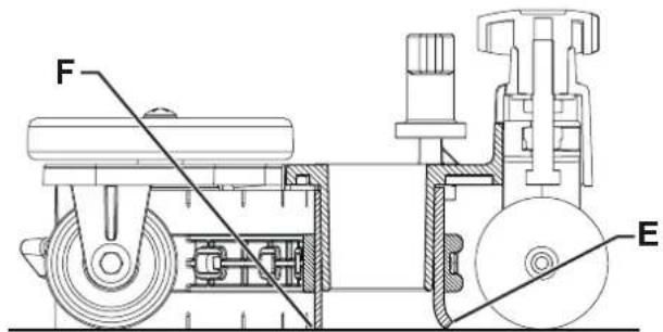
Abbildung 3
P100951
natural_image
Top-down line drawing of a car on a grid background with a gray arrow indicating direction (no text or symbols)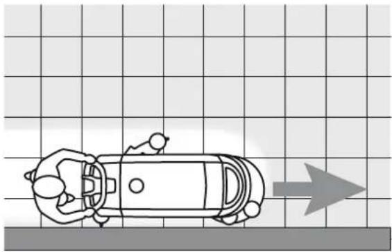
natural_image
Top-down schematic of a car with directional arrow on grid background (no text or symbols)Abbildung 5
P100953

HINWEIS!
Abbildung 7
P100955
BÜRSTE REINIGEN

HINWEIS!
Abbildung 8
P100956
Abbildung 9
P100957
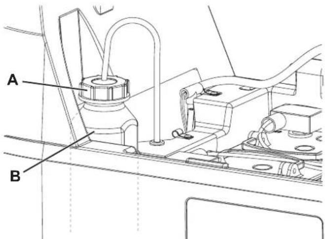
Abbildung 10
P100958
CONSERVATION DU MANUEL....2
DÉCLARATION DE CONFORMITÉ 2
DONNÉES D'IDENTIFICATION 2
AUTRES MANUELS DE RÉFÉRENCE....2
PIÈCES DE RECHANGE ET ENTRETIEN 2
MODIFICATIONS ET AMÉLIORATIONS....3
CAPACITÉS OPÉRATIONNELLES....3
CONVENTIONS .... 3
DÉBALLAGE / LIVRAISON....3
SÉCURITÉ 3
SYMBOLES VISIBLES SUR LA MACHINE....3
SYMBOLES UTILISÉS DANS LE MANUEL....4
INSTRUCTIONS GÉNÉRALES 4
DESCRIPTION DE LA MACHINE 6
STRUCTURE DE LA MACHINE....6
TABLEAU DE BORD 8
ACCESSOIRES / OPTIONS....9
CARACTÉRISTIQUES TECHNIQUES 9
SCHÉMA ÉLECTRIQUE....10
UTILISATION/FONCTIONNEMENT 11
CONTRÔLE / PRÉPARATION DES BATTERIES SUR UNE MACHINE NEUVE ....11
INSTALLATION ET CONFIGURATION DU TYPE DE BATTERIE (WET OU GEL)....11
AVANT LA MISE EN MARCHE DE LA MACHINE 12
DÉMARRAGE DE LA MACHINE (LAVAGE/SÉCHAGE)....14
ARRÊT DE LA MACHINE 16
VIDANGE DES RÉSERVOIRS....17
APRÈS L'UTILISATION DE LA MACHINE 17
INACTIVITÉ PROLONGÉE DE LA MACHINE 17
ENTRETIEN 18
PLAN D'ENTRETIEN PROGRAMMÉ....18
CHARGEMENT DES BATTERIES 19
NETTOYAGE DE L'EMBOUCHURE 20
CONTRÔLE ET REMPLACEMENT DES LAMELLES EN CAOUTCHOUC DE L'EMBOUCHURE 20
NETTOYAGE DE LA BROSSE....21
NETTOYAGE DU RÉSERVOIR DE L'EAU DE RÉCUPÉRATION 21
NETTOYAGE DU FILTRE DE LA SOLUTION....22
NETTOYAGE DU RÉSERVOIR DE DÉTERGENT ET DU SYSTÈME DE DÉTERGENT 22
CONTRÔLE / REMPLACEMENT DES FUSIBLES 23
DÉPISTAGE DES PANNES....23
MISE À LA FERRAILLE 24
INTRODUCTION

REMARQUE
CONSERVATION DU MANUEL
DÉCLARATION DE CONFORMITÉ
STRUCTURE DE LA MACHINE
P100944
STRUCTURE DE LA MACHINE (suite)
P100945
TABLEAU DE BORD
P100946
ACCESSOIRES / OPTIONS
Figure 2
P100949
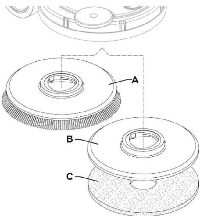
Figure 2
P100950

Figure 3
P100951
natural_image
Top-down line drawing of a car on a grid background with a gray arrow indicating direction (no text or symbols)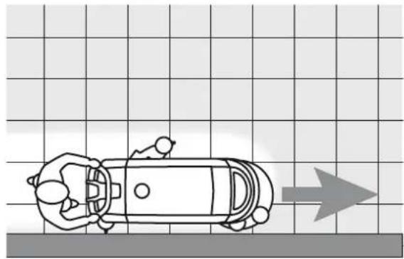
natural_image
Top-down line drawing of a car on a grid background with an arrow indicating direction (no text or symbols)Figure 5
P100953

AVERTISSEMENT!
Figure 7
P100955
NETTOYAGE DE LA BROSSE

AVERTISSEMENT!
Figure 8
P100956
NETTOYAGE DU FILTRE DE LA SOLUTION
Figure 9
P100957

Figure 10
P100958
CONTRÔLE / REMPLACEMENT DES FUSIBLES

REMARQUE
MANUAL PURPOSE AND CONTENTS 2
TARGET 2
HOW TO KEEP THIS MANUAL....2
DECLARATION OF CONFORMITY 2
IDENTIFICATION DATA....2
OTHER REFERENCE MANUALS....2
SPARE PARTS AND MAINTENANCE....2
CHANGES AND IMPROVEMENTS 3
VISIBLE SYMBOLS ON THE MACHINE....3
SYMBOLS THAT APPEAR ON THIS MANUAL....4
GENERAL INSTRUCTIONS 4
MACHINE DESCRIPTION 6
MACHINE STRUCTURE 6
CONTROL PANEL 8
ACCESSORIES/OPTIONS....9
TECHNICAL DATA 9
WIRING DIAGRAM....10
USE/OPERATION 11
BATTERY CHECK/SETTING ON A NEW MACHINE 11
BATTERY INSTALLATION AND SETTING (WET OR GEL)....11
BEFORE MACHINE START-UP 12
STARTING UP THE MACHINE (SCRUBBING/DRYING)....14
STOPPING THE MACHINE....16
TANK EMPTYING....17
AFTER USING THE MACHINE....17
MACHINE LONG INACTIVITY 17
MAINTENANCE 18
SCHEDULED MAINTENANCE TABLE 18
BATTERY CHARGING 19
SQUEEGEE CLEANING 20
SQUEEGEE BLADE CHECK AND REPLACEMENT 20
BRUSH CLEANING 21
RECOVERY TANK CLEANING 21
SOLUTION FILTER CLEANING 22
DETERGENT TANK AND DETERGENT SYSTEM CLEANING....22
FUSE CHECK/REPLACEMENT....23
TROUBLESHOOTING 23
SCRAPPING 24
INTRODUCTION

NOTE
The numbers in brackets refer to the components shown in Machine Description chapter.
MANUAL PURPOSE AND CONTENTS
The purpose of this Manual is to provide the operator with all necessary information to use the machine properly, in a safe and autonomous way. It contains information about technical data, safety, operation, storage, maintenance, spare parts and disposal. Before performing any procedure on the machine, the operators and qualified technicians must read this Manual carefully. Contact Nilfisk in case of doubts concerning the interpretation of the instructions and for any further information.
TARGET
This Manual is intended for operators and technicians qualified to perform the machine maintenance.
The operators must not perform procedures reserved for qualified technicians. Nilfisk will not be answerable for damages coming from the non-observance of this prohibition.
HOW TO KEEP THIS MANUAL
The Instructions for Use Manual must be kept near the machine, inside an adequate case, away from liquids and other substances that can cause damage to it.
DECLARATION OF CONFORMITY
The Declaration of Conformity, supplied with the machine, certifies the machine conformity with the law in force.

NOTE
Two copies of the original declaration of conformity are provided together with the machine documentation.
IDENTIFICATION DATA
The machine serial number and model name are marked on the plate (3).
Year of production (Date code: A17 means January 2017) and product code are marked on the same plate.
This information is useful when requiring machine spare parts. Use the following table to write down the machine identification data.
| MACHINE model...... |
| PRODUCT code...... |
| MACHINE serial number...... |
OTHER REFERENCE MANUALS
Electronic Battery Charger Manual (if equipped), to be considered as integral part of this Manual. Moreover, the following Manuals are available:
– Spare Parts List (supplied with the machine)
– Service Manual (that can be consulted at Nilfisk Service Centers)
SPARE PARTS AND MAINTENANCE
All necessary operating, maintenance and repair procedures must be performed by qualified personnel or by Nilfisk Service Centers. Only original spare parts and accessories must be used. Contact Nilfisk for service or to order spare parts and accessories, specifying the machine model, product code and serial number.
CHANGES AND IMPROVEMENTS
Nilfisk constantly improves its products and reserves the right to make changes and improvements at its discretion without being obliged to apply such benefits to the machines that were previously sold.
Any change and/or addition of accessory must be approved and performed by Nilfisk.
These scrubber-dryers are designed to clean (scrubbing and drying) smooth and solid floors, in commercial or industrial environment, under safe operation conditions by a qualified operator.
The scrubber-dryers cannot be used for fitted carpet and carpet cleaning.
CONVENTIONS
Forward, backward, front, rear, left or right are intended with reference to the operator's position, that is to say in driving position with the hands on the handlebar (1).
UNPACKING/DELIVERY
To unpack the machine, carefully follow the instructions on the packing.
When the machine is delivered, check that the packing and the machine were not damaged during transportation.
In case of visible damages, keep the packing and have it checked by the carrier that delivered it. Call the carrier immediately to fill in a damage claim.
Please check that the following items have been supplied with the machine:
- Technical documents:
- Scrubber-dryer Instructions for Use Manual
• Electronic Battery Charger Manual (if equipped)
• Scrubber-dryer Spare Parts List
• No. 1 connector for battery charger (for machines without on board battery charger)
• No. 2 lamellar fuses
SAFETY
The following symbols indicate potentially dangerous situations. Always read this information carefully and take all necessary precautions to safeguard people and property.
The operator's cooperation is essential in order to prevent injury. No accident prevention program is effective without the total cooperation of the person responsible for the machine operation. Most of the accidents are caused by failure to comply with the simplest rules for exercising prudence.
VISIBLE SYMBOLS ON THE MACHINE
WARNING!
Carefully read all the instructions before performing any operation on the machine.

WARNING!
Do not wash the indicated area with direct or pressurized water jets.
WARNING!
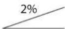
Do not use the machine on slopes with a gradient exceeding the specifications.
SYMBOLS THAT APPEAR ON THIS MANUAL

DANGER!
It indicates a dangerous situation with risk of death for the operator.

WARNING!
It indicates a potential risk of injury for people.

CAUTION!
It indicates a caution or a remark related to important or useful functions.
Pay careful attention to the paragraphs marked by this symbol.

NOTE
It indicates a remark related to important or useful functions.

CONSULTATION
It indicates the necessity to refer to the Instructions for Use Manual before performing any procedure.
GENERAL INSTRUCTIONS
Specific warnings and cautions to inform about potential damages to people and machine are shown below.

DANGER!
- Before performing any machine maintenance, repair, cleaning or replacement procedure, disconnect the battery connector and remove the ignition key (if equipped).
- This machine must be used by properly trained operators only.
- Do not wear jewels when working near electrical components.
- Do not work under the lifted machine without supporting it with safety stands.
- Do not operate the machine near toxic, dangerous, flammable and/or explosive powders, liquids or vapours. This machine is not suitable for collecting dangerous powders.
- When using lead (WET) batteries, keep sparks, flames and smoking materials away from the batteries. During the normal operation explosive gases are released.
- When using lead (WET) batteries, battery charging produces highly explosive hydrogen gas. During battery charging, lift the recovery tank and perform this procedure in well-ventilated areas and away from naked flames.

WARNING!
- Carefully read all the instructions before performing any maintenance/repair procedure.
- Before using the battery charger, ensure that frequency and voltage values, indicated on the machine serial number plate, match the electrical mains voltage.
- Do not pull or carry the machine by the battery charger cable and never use the battery charger cable as a handle. Do not close a door on the battery charger cable, or pull the battery charger cable around sharp edges or corners. Do not run the machine on the battery charger cable.
- Keep the battery charger cable away from heated surfaces.
- Do not charge the batteries if the battery charger cable or the plug are damaged. If the machine is not working as it should, has been damaged, left outdoors or dropped into water, return it to the Service Center.
- To reduce the risk of fire, electric shock, or injury, do not leave the machine unattended when it is plugged in. Before performing any maintenance procedure, disconnect the battery charger cable from the electrical mains.
- Do not smoke while charging the batteries.
- To avoid any unauthorized use of the machine, remove the ignition key.
- Do not leave the machine unattended without being sure that it cannot move independently.

WARNING!
- Always protect the machine against the sun, rain and bad weather, both under operation and inactivity condition. This machine must be used indoors in dry conditions, it must not be used or kept outdoors in wet conditions.
- Before using the machine, close all doors and/or covers as shown in the Instructions for Use Manual.
- This machine is not intended for use by persons (including children) with reduced physical, sensory or mental capabilities, or lack of experience and knowledge, unless they have been given supervision or instruction concerning use of the machine by a person responsible for they safety. Children should be supervised to ensure that they do not play with the machine.
- Close attention is necessary when used near children.
- Use only as shown in this Manual. Use only Nilfisk's recommended accessories.
- Check the machine carefully before each use, always check that all the components have been properly assembled before use. If the machine is not perfectly assembled it can cause damages to people and properties.
Take all necessary precautions to prevent hair, jewels and loose clothes from being caught by the machine moving parts.
- Do not use the machine on slopes.
- Do not tilt the machine more than the angle indicated on the machine itself, in order to prevent instability.
- Do not use the machine in particularly dusty areas.
- Use the machine only where a proper lighting is provided.
- While using this machine, take care not to cause damage to people or objects.
- Do not bump into shelves or scaffoldings, especially where there is a risk of falling objects.
-
Do not lean liquid containers on the machine, use the relevant can holder.
-
The machine working temperature must be between 0^ and +40^ .
- The machine storage temperature must be between 0^ and +40^ .
- The humidity must be between 30% and 95% .
- When using floor cleaning detergents, follow the instructions on the labels of the detergent bottles.
- To handle floor cleaning detergents, wear suitable gloves and protections.
- Do not use the machine as a means of transport.
- Do not allow the brush to operate while the machine is stationary to avoid damaging the floor.
– In case of fire, use a powder fire extinguisher, not a water one.
- Do not tamper with the machine safety guards and follow the ordinary maintenance instructions scrupulously.
- Do not allow any object to enter into the openings. Do not use the machine if the openings are clogged. Always keep the openings free from dust, hairs and any other foreign material which could reduce the air flow.
- Do not remove or modify the plates affixed to the machine.
- (Only for machines with drive system): When the machine is to be pushed for service reasons (missing or discharged batteries, etc.), the speed must not exceed 4 km/h.
-
This machine cannot be used on roads or public streets.
-
Pay attention during machine transportation when temperature is below freezing point. The water in the recovery tank or in the hoses could freeze and seriously damage the machine.
- Use only the brushes supplied with the machine or those specified in the Instructions for Use Manual. Using other brushes could reduce safety.
- In case of machine malfunctions, ensure that these are not due to lack of maintenance. If necessary, request assistance from the authorised personnel or from an authorised Service Center.
- If parts must be replaced, require ORIGINAL spare parts from an Authorised Dealer or Retailer.
- To ensure machine proper and safe operation, the scheduled maintenance shown in the relevant chapter of this Manual, must be performed by the authorised personnel or by an authorised Service Center.
- Do not wash the machine with direct or pressurised water jets, or with corrosive substances.
- The machine must be disposed of properly, because of the presence of toxic-harmful materials (batteries, etc.), which are subject to standards that require disposal in special centres (see Scrapping chapter).
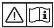
MACHINE DESCRIPTION
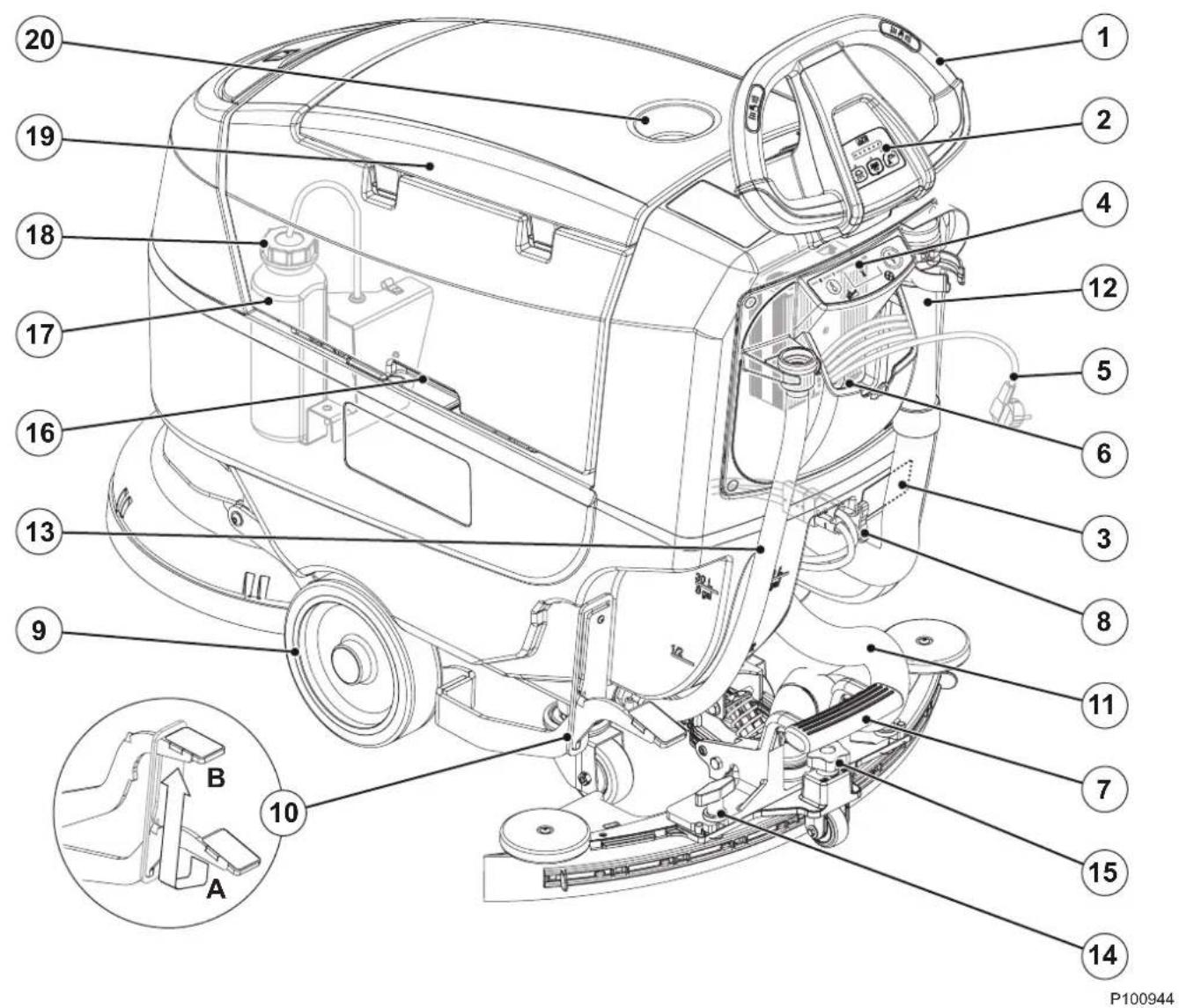
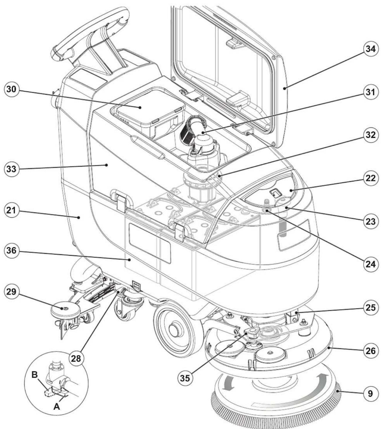
MACHINE STRUCTURE
- Drive handlebar
- Control panel (see the following paragraph)
- Serial number plate/technical data/conformity certification
- Battery charger (optional) (**)
- Battery charger cable (optional) (**)
- Battery charger cable housing and document holder
- Squeegee lifting/lowering pedal
- Battery connector (red).
This connector also works as EMERGENCY push-button, to stop immediately all functions.
-
Front driving wheels (*)
-
Brush deck lifting/lowering pedal
A) Pedal position for lifted deck
B) Pedal position for lowered deck -
Squeegee vacuum hose
-
Recovery water drain hose
- Solution drain and level check hose
- Squeegee mounting handwheels
- Squeegee adjusting knob
- Tank lifting handle
- Detergent System detergent canister (optional)
- Detergent canister plug (optional)
- Recovery tank cover
- Can holder
(*) Only for drive version
(**) Standard on FULL PACKAGE version
MACHINE STRUCTURE (Continues)
- Solution tank
- Solution tank filler plug
- Removable solution feed hose
- "Garden" intake for loading the solution
- Solenoid valve
- Disc brush deck
- Brush
- Solution valve:
A) Open valve
B) Closed valve
- Squeegee
- Debris collection tank
- Vacuum grid with automatic shut-off float
- Vacuum system motor
- Recovery tank
- Recovery water tank cover (open)
- Machine forward speed adjusting knob
- Batteries (optional) (**)
(**) Standard on FULL PACKAGE version
P100945
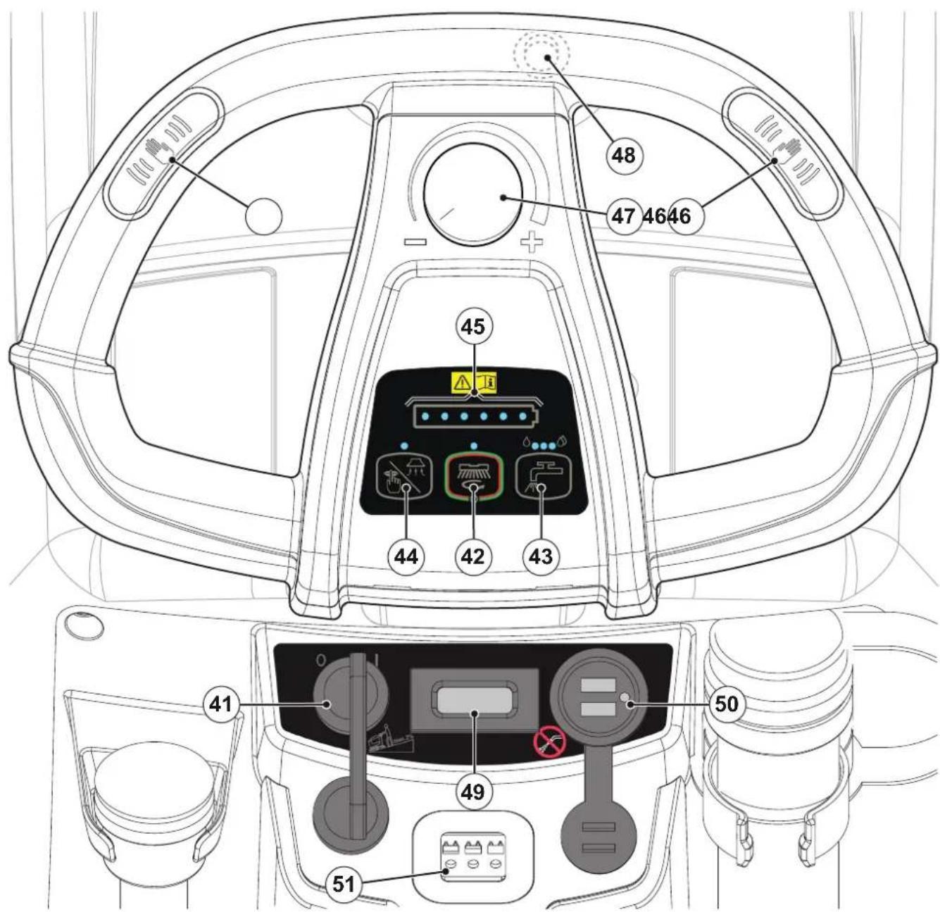
CONTROL PANEL
-
Ignition key (optional, standard on drive version)
-
Main machine start and stop push-button:
• LED on - machine scrubbing/drying
• LED flashing - brush engage/disengage function
- Solution push-button:
• Left LED on - minimum solution flow
• Central LED on - medium solution flow
• Right LED on - maximum solution flow
• LEDs off - solution deactivated
- Vacuum system push-button:
• LED on - vacuum system activated
• LED flashing - silenced vacuum system activated
-
Battery symbol:
-
1 ÷ 6 LEDs on - battery charge level
• 1 LED flashing - discharged batteries -
Operator's presence sensors
- Speed adjuster (*)
- Reverse gear switch (*)
- Hour counter (**)
- USB port (optional)
-
Battery charger inspection window (optional) (**):
-
Green LED (the battery charger is on and batteries are charged)
- Yellow LED (the battery charger is on and batteries are semi-discharged)
- Red LED (the battery charger is on and it is charging the batteries)
(*) Only for drive version
(**) Standard on FULL PACKAGE version
P100946
ACCESSORIES/OPTIONS
In addition to the standard components, the machine can be equipped with the following accessories/options, according to the machine specific use:
- Ignition key
– Squeegee blades of different materials
- GEL/AGM batteries
- Detergent System
- Electronic battery charger
– Front and rear wheels of different materials
- Brushes/pads of different materials
- Hour counter
- Splash guard
- USB port
For further information concerning the optional accessories, contact an authorised Retailer.
TECHNICAL DATA
| Model | SC401SCRUBTEC 344no drive | SC401drive |
| Solution tank capacity 30 litres | ||
| Recovery tank capacity 30 litres | ||
| Machine length 1,180 mm | ||
| Machine width with squeegee 720 mm | ||
| Machine width without squeegee 458 mm | ||
| Machine height 1,055 mm | ||
| Cleaning width 430 mm | ||
| Front wheel diameter 200 mm | ||
| Front wheel specific pressure on the floor 0.8 N/mm | 2 | |
| Rear wheel diameter 80 mm | ||
| Rear wheel specific pressure on the floor 2.0 N/mm | 2 | |
| Brush/pad diameter 430 mm | ||
| Brush pressure | 25 kg | |
| Solution flow values | 0.3 - 0.7 - 2.0 l/min | |
| Detergent System detergent percentage | - | 0.25 + 2.0 % |
| Sound pressure level at workstation (ISO 11201, ISO 4871, EN 60335-2-72) (LpA) | 65 ± 3 dB(A) | |
| Sound pressure level at workstation in silent mode (LpA) | 60 ± 3 dB(A) | |
| Machine sound power level (granted value, ISO 3744, ISO 4871, EN 60335-2-72) (LwA) | 80 dB(A) | |
| Vibration level at the operator's arms (ISO 5349-1, EN 60335-2-72) | < 2.5 m/s2 | |
| Maximum gradient when working | 2 % | |
| Drive system motor power | - | 150 W |
| Drive speed (variable) | - | 0 - 5 km/h |
| Vacuum system motor power | 280 W | |
| Vacuum system circuit capacity | 900 mm H2O | |
| Brush motor power | 450 W | |
| Brush motor speed | 140 rpm | |
| Total power draw (EN 60335-2-72) | 0.5 kW | 0.6 kW |
| IP protection class | X4 | |
| Protection class (electric) | III (I for the battery charger) | |
| Battery compartment size | 350 x 350 x 260 mm | |
| System voltage | 24V | |
| Standard batteries (2) | - | 12V-76 Ah GELMONOBLOC |
| Battery charger | - | 24V 10A |
| Operating time (standard batteries) (EN 60335-2-72) | 2.6 hour | 2.4 hour |
| Weight without batteries and with empty tanks | 61 kg | 73 kg |
| Gross vehicle weight (GVW) | 151 kg | 163 kg |
| Shipping weight (basic / full package) | 97 kg / 154 kg | 109 kg / 166 kg |
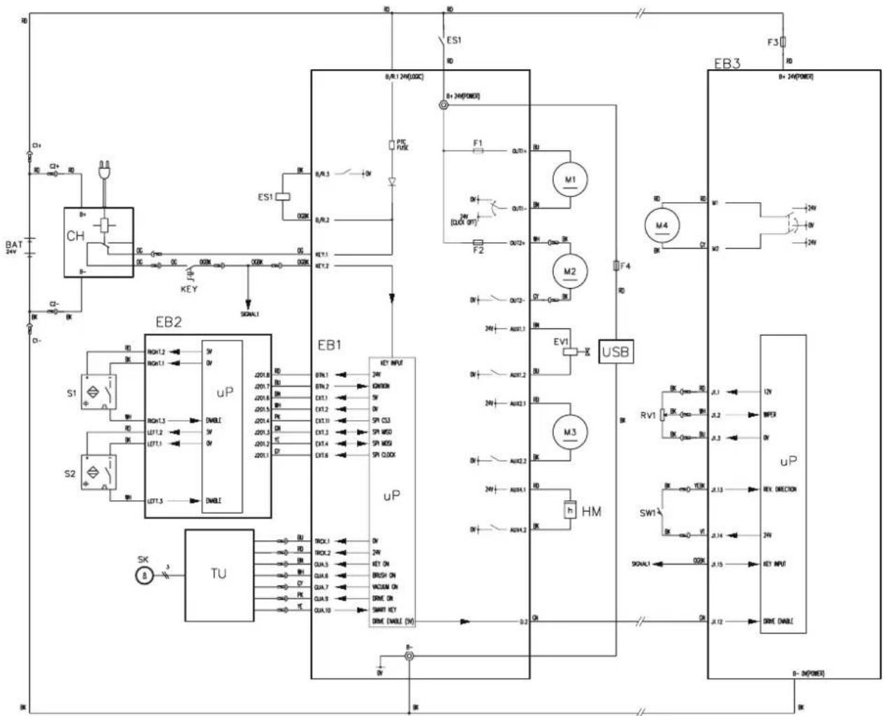
WIRING DIAGRAM
Key
| BAT 24 V batteries (*) |
| C1 Battery connector |
| C2 Battery charger connector |
| CH Battery charger (optional) |
| EB1 Function electronic board |
| EB2 User interface electronic board |
| EB3 Drive system electronic board (drive) |
| ES1 Function electronic board relay |
| EV1 Solenoid valve |
| F1 Brush motor fuse |
| F2 Vacuum motor fuse |
| F3 Drive system motor fuse (drive) |
| F4 USB port fuse (optional) |
| HM Hour counter (optional) |
| KEY Ignition key (*) |
| M1 Brush motor |
| M2 Vacuum system motor |
| M3 Detergent pump (*) |
| M4 Drive system motor (drive) |
| RV1 Speed potentiometer (drive) | |
| S1,S2 Operator's presence sensor | |
| SK Smart key (optional) | |
| SW1 Reverse gear switch (drive) | |
| TU | Trackclean (optional) |
| USB | USB port (optional) |
(\*) Optional for BASIC versions
Colour codes
| BK Black | |
| BU Blue | |
| BN Brown | |
| GN | Green |
| GY Grey | |
| OG Orange | |
| PK Pink | |
| RD Red | |
| VT Violet | |
| WH | White |
| YE Yellow | |
flowchart
graph TD
    subgraph EB1
        A["uP"] --> B["USB"]
        B --> C["USB"]
        C --> D["USB"]
        D --> E["USB"]
    end

    subgraph EB2
        F["EB2"] --> G["USB"]
        G --> H["USB"]
        H --> I["USB"]
    end

    subgraph EB3
        J["USB"] --> K["USB"]
        K --> L["USB"]
        L --> M["USB"]

    subgraph S1
        N["S1"] --> O["USB"]
        P["S2"] --> Q["USB"]
    end

    subgraph S2
        R["S2"] --> S["USB"]
        T["S2"] --> U["USB"]
    end

    subgraph TU
        V["TU"] --> W["USB"]
        X["TU"] --> Y["USB"]
    end

    subgraph KEY
        Z["KEY"] --> AA["0V"]
        AB["0V"] --> AC["0V"]
        AD["0V"] --> AE["0V"]
        AF["0V"] --> AG["0V"]
        AH["0V"] --> AI["0V"]
        AJ["0V"] --> AK["0V"]
        AL["0V"] --> AM["0V"]
        AN["0V"] --> AO["0V"]
        AP["0V"] --> AQ["0V"]
        AR["0V"] --> AS["0V"]
        AT["0V"] --> AU["0V"]
        AV["0V"] --> AW["0V"]
        AX["0V"] --> AY["0V"]
        AZ["0V"] --> BA["0V"]
        BB["0V"] --> BC["0V"]
        BD["0V"] --> BE["0V"]
        BF["0V"] --> BG["0V"]
        BH["0V"] --> BI["0V"]
        BJ["0V"] --> BK["0V"]
        BL["0V"] --> BM["0V"]
        BN["0V"] --> BO["0V"]
        BP["0V"] --> BQ["0V"]
        BR["0V"] --> BS["0V"]
        BT["0V"] --> BU["0V"]
        BV["0V"] --> BW["0V"]
        BX["0V"] --> BY["0V"]
        BZ["0V"] --> CA["0V"]
        CB["0V"] --> CD["0V"]
        CE["0V"] --> CF["0V"]
        GD["0V"] --> DH["0V"]
        DI["0V"] --> DJ["0V"]
        DK["0V"] --> DL["0V"]
        DV["0V"] --> DW["0V"]
        DX["0V"] --> DY["0V"]
        DXB["0V"] --> DYD["0V"]
        DXC["0V"] --> DYE["0V"]
        DXF["0V"] --> DYG["0V"]
        DXH["0V"] --> DYH["0V"]
        DXI["0V"] --> DYJ["0V"]
        DXK["0V"] --> DYL["0V"]
        DXM["0V"] --> DYN["0V"]
        DXO["0V"] --> DYO["0V"]
        DXP["0V"] --> DYP1["0V"]
        DXQ["0V"] --> DYQ1["0V"]
        DXR["0V"] --> DYR1["0V"]
        DXS["0V"] --> DYS1["0V"]
        DXT["0V"] --> DYT1["0V"]
        DXU["0V"] --> DYU1["0V"]
        DXW["0V"] --> DYW1["0V"]
        DXXN["0V"] --> DYXN1["0V"]
        DXYN1["0V"] --> DYYN1["0V"]

    subgraph EB1
        AB["uP"] --> AC["uP"]
    end

    subgraph EB2
        B["uP"] --> AC["uP"]
    end

    subgraph EB3
        K["uP"] --> L["uP"]
    end

    style EB1 fill:#f9f,stroke:#333
    style EB2 fill:#ccf,stroke:#333
    style EB3 fill:#cfc,stroke:#333
P100947
USE/OPERATION

WARNING!
On some points of the machine there are some adhesive plates indicating:
- DANGER
- WARNING
- CAUTION
- CONSULTATION
While reading this Manual, the operator must pay particular attention to the symbols shown on the plates (see Visible Symbols On The Machine paragraph).
Do not cover these plates for any reason and immediately replace them if damaged.
BATTERY CHECK/SETTING ON A NEW MACHINE

WARNING!
The electric components of the machine can be seriously damaged if the batteries are either improperly installed or connected.
The batteries must be installed by qualified personnel only. Set the battery charger (optional) according to the battery type (WET or GEL/AGM).
Check the batteries for damage before installation.
Disconnect the battery connector and the battery charger plug.
Handle the batteries with great care.
Install the battery terminal protection caps supplied with the machine.
The machine requires two 12 V batteries, connected according to the diagram (28).
The machine can be supplied in one of the following modes:
Batteries already installed on the machine
- Ensure that the battery connector (8) is connected.
- When first using the machine with new batteries, perform a full charging cycle (see the procedure in Maintenance chapter).
Without batteries
- Buy appropriate batteries (see "Technical Data" paragraph).
- Set the machine according to the type of batteries installed (WET or GEL) as shown in the following paragraph.
BATTERY INSTALLATION AND SETTING (WET OR GEL)
Battery Installation
- If equipped, remove the ignition key (41).
- Disconnect the battery connector (8).
- Lift the cover (34) and check that the recovery tank (33) is empty; if not, empty it using the drain hose (12).
- Close the cover (34).
- Grasp the handle (16) and carefully lift the tank (33).
- The machine is supplied with cables suitable to install 2 12 V batteries. Carefully lift the batteries up to the compartment, then install them correctly.
- Route and install the battery cables as shown in the diagram in Figure 1, then tighten the nut on each battery terminal.
- Place the protection cap on each terminal, then connect the battery connector (8).
- Grasp the handle (16) and carefully lower the tank (33).
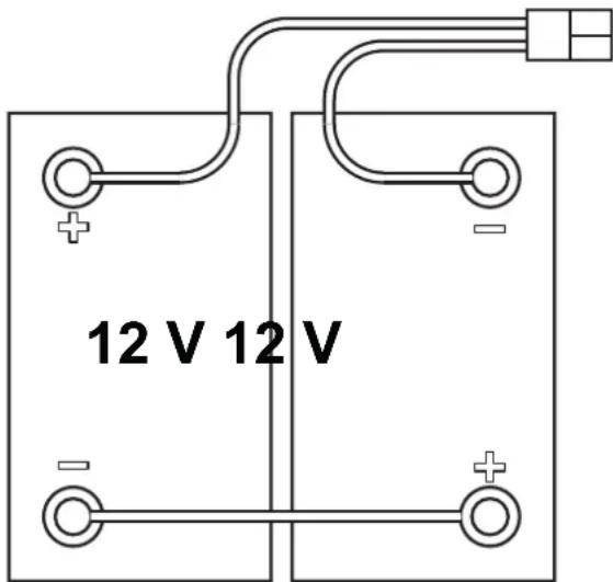
Figure 1
P100948
Battery type setting
Set the electronic board of the machine according to the type of batteries installed (WET or GEL) as shown below:
- (If equipped) Turn the ignition key (41) to "I". Press the main push-button (42) to turn on the machine, then detect the current setting by checking in the very first seconds the battery symbol LED flashing (see Figure 2):
- If the setting is to be changed, press the push-button (44) for 3 seconds.
- Within 3 seconds, shortly press the push-button (44) to select a new setting.
- Wait 3 seconds for the battery symbol to display the battery charge status.

WARNING!
In the machines equipped with on-board battery charger, the installed batteries (WET or GEL/AGM) may require a specific charging algorithm: always contact a Nilfisk Service Center to set the charging algorithm most appropriate for the installed batteries.
Battery Charging
- Fully charge the batteries (see the procedure in Maintenance chapter).
BEFORE MACHINE START-UP
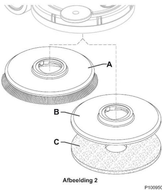
Brush or pad-holder installation
According to the kind of cleaning to be performed, the machine can be equipped either with the brush (A, Fig. 2) or the pad-holder (B) with pad (C) together with the appropriate deck.
- Place the brush (A) or the pad-holder (B) under the brush deck (26).
- (If equipped) Turn the ignition key (41) to "I". Press the main push-button (42) to start the machine.
- Press the main push-button (42, LED on) again.
- Lower the brush deck by pressing the pedal (10-B).
- To activate the brush engagement function, press the push-buttons (44) and (42) simultaneously for one second.
Brush or pad-holder removal
- Press the main push-button (42, LED off).
- Lift the brush deck by pressing the pedal (10-A).
- To activate the brush disengagement function, press the push-buttons (44) and (42) simultaneously for one second, then wait for the brush to fall on the floor.

NOTE
When the brush engagement/disengagement function is activated, the push-button LED (42) flashes.
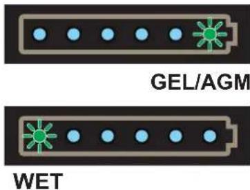
Figure 2
P100949

Figure 2
P100950
Available brushes and their relevant application guides (suggestions only)
| Models 46 GRIT 80 GRIT 180 GRIT 240 GRIT 500 | GRIT PROLE | NE PROLITE | UNION MIX | ||||
| General cleaning: | |||||||
| Concrete | |||||||
| Terrazzo floor | |||||||
| Ceramic tiles/quarrystones | |||||||
| Marble | |||||||
| Vinyl tiles | |||||||
| Rubber tiles | |||||||
| Polishing: | |||||||
| Rubber tiles | |||||||
| Marble | |||||||
| Vinyl tiles | |||||||
Squeegee installation
- Install the squeegee (A, Fig. 3) and fasten it to the bracket (C) with the handwheels (B).
- If necessary, adjust the squeegee with the knob (D) so that the rear blade (E) and front blade (F) touch the floor as shown in the figure.
Solution tank filling

CAUTION!
Use only low-foam and non-flammable detergents, intended for automatic scrubber applications.

WARNING!
When using floor cleaning detergents, follow the instructions on the labels of the detergent bottles.
To handle floor cleaning detergents, wear suitable gloves and protections.

NOTE
If the machine is equipped with Detergent System pour clean water in the tank, otherwise pour solution.
- Ensure that the solution valve (28) is open (28-B).
- To fill the solution tank (21) lift the plug (22) and use the removable filler hose (23) or the "garden" intake (24).
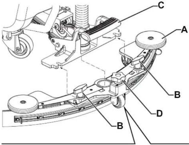
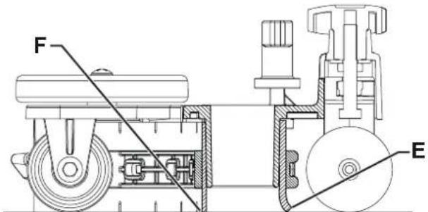
Figure 3
P100951
(For machines without Detergent System)
- Fill the tank (21) with a solution suitable for the work to be performed.
Do not fill the tank completely, leave a few inches from the edge. Use the level hose (13) as reference. Always follow the dilution instructions on the label of the chemical product used to prepare the solution. The solution temperature must not exceed 40 °C.
(For machines with Detergent System)
- Fill the tank (21) with clean water.
Do not fill the tank completely, leave a few inches from the edge. Use the level hose (13) as reference. The water temperature must not exceed 40 °C .
Detergent tank filling (For machines with Detergent System)
- Lift the cover (34) and check that the recovery tank (33) is empty; if not, empty it using the drain hose (12).
- Close the cover (34).
- Grasp the handle (16) and carefully lift the tank (33).
- Fill the tank (17) with a detergent suitable for the work to be performed (highly concentrated detergent). Do not fill the detergent tank completely, leave a few inches from the edge.

CAUTION!
Use only low-foam and non-flammable detergents, intended for automatic scrubber applications.
STARTING UP THE MACHINE (SCRUBBING/DRYING)
- Prepare the machine as shown in the previous paragraph.
- (If equipped) Turn the ignition key (41) to "I".
Press the main push-button (42) to start the machine.

NOTE
First flashes on the battery symbol (45) indicate the type of batteries installed (see paragraph "Battery type setting").

NOTE
Check the battery charge level.
6 LEDs on the battery symbol (45) indicate the battery charge level.
When there is only one LED turned on and flashing, it is advisable to charge the batteries, because the residual autonomy will last for a few minutes, depending on battery characteristics and work to be performed (for battery charging procedure see the Maintenance chapter).

CAUTION!
Do not use the machine with discharged batteries, to avoid damaging the batteries and reducing the battery life.
-
Drive the machine to the working place:
-
(Only for no drive versions) push the machine with the hands on the handlebar (1).
- (Only for drive versions) start the machine with at least one hand on the presence sensors (46) on the handlebar to move forward. The maximum forward speed can be adjusted with the adjuster (47). For reverse gear, press the push-button (48) and place the hands on the sensors (45).

NOTE
When the machine is turned on and the hands are on the presence sensors, if the machine is equipped with hour counter (49), it is possible to read the total number of working hours performed.
- Lower the squeegee (29) with the pedal (7).
- Lower the brush deck by pressing the pedal (10-B).
- Press the main push-button (42, LED on) to start the machine scrubbing/drying functions.
- Manoeuvre the machine by placing your hands on the sensors (46) on the handlebar, and start scrubbing/drying the floor.

NOTE
The presence sensors (46) on the handlebar allow the brush and solution to be started up (on drive versions) only when the operator has the hands on at least one of the knobs.
-
(Only for drive versions) If necessary, adjust the maximum speed with the adjuster (47).
-
To avoid marks or lines on delicate floors, use the "pre wetted" function, which dampens the brush before starting the operation.
To activate this function, press the push-buttons (42) and (43) together for 10/20 seconds.

NOTE
The "pre wetted" function stays only as long as the push-buttons (42) and (43) are pressed.
- Adjust the detergent flow by pressing the push-button (43) as necessary, depending on the type of cleaning to be performed. When the LED is on, it indicates the value in litres per minute of solution flow supplied, as shown in the Figure 4. When the LEDs are off, the solution flow is stopped.
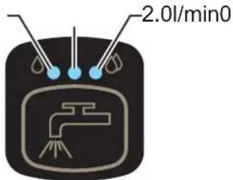
Figure 4
P100952
-
If necessary, deactivate the vacuum system by pressing the push-button (44, LED off), then press it again to reactivate it (LED on). To reduce the noise, turn on the vacuum system mute function by pressing the push-button (44).
-
(Only for no drive versions) If necessary, stop the machine and turn the forward speed adjusting handwheel (35) as shown below:
-
Turn it counter-clockwise to increase the forward speed;
- Turn it clockwise to decrease the forward speed.

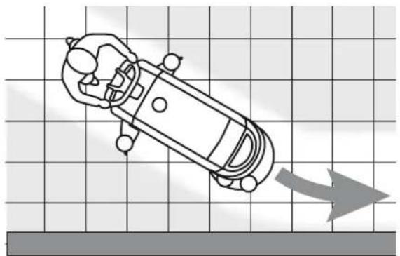
NOTE
For correct scrubbing/drying of floors at the sides of the walls, Nilfisk suggests to go near the walls with the right side of the machine as shown in figure 5.
natural_image
Top-down line drawing of a car on a grid background with a gray arrow indicating direction (no text or symbols)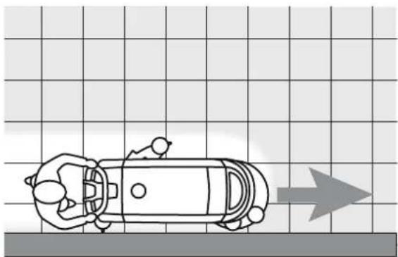
natural_image
Top-down line drawing of a car on a grid background with an arrow indicating direction (no text or symbols)Figure 5
P100953

CAUTION!
To avoid any damage to the floor surface, turn off the brush when the machine stops in one place.
Adjusting of detergent concentration in the washing water
(For machines with Detergent System)
The system for mixing the detergent in the washing water is automatically activated when the brush is running.
The percentage of detergent added to the washing water is set to 0,25%, to change the setting perform the following procedure:
- Press the push-button (43) for more than two seconds to perform the adjustment.
The set percentage depends on the relevant LED turned on, on the battery charge symbol, as shown in Figure 6.
- Press the push-button (43) repeatedly to change the setting or to reset it (all LEDs off).

NOTE
The setting is stored 3 minutes after releasing all push-buttons.
Detergent percentage setting is stored into memory, even if the machine is switched off.
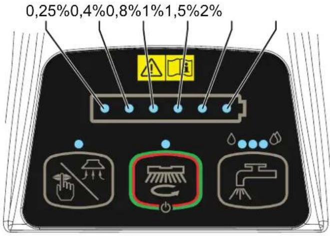
Figure 6
P100954
Battery discharge during operation
When there is only one LED turned on and flashing on the battery symbol (45), it is advisable to charge the batteries, because the residual autonomy will last for a few minutes (depending on battery characteristics and work to be performed).
When the LED flashes, the brush is automatically tuned off after a few seconds, while the vacuum system and the drive system (drive version) stay on, to finish drying the floor and drive the machine to the appointed recharging area.

CAUTION!
Do not use the machine with discharged batteries, to avoid damaging the batteries and reducing the battery life.
STOPPING THE MACHINE
-
Stop the brush rotation and the drive system (drive version) by releasing the presence sensors (46) and stop the machine with the handle (1).
-
Press the push-button (42) for 2 seconds to stop the machine. (If equipped) Turn the ignition key (41) to "0".

NOTE
If the machine is on but not working, it automatically turns off after 5 minutes.
- Make sure that the machine cannot move independently.

CAUTION!
In the event of an emergency, to stop all machine functions immediately, disconnect the battery connector (8). Reset the machine functions by connecting again the connector.
TANK EMPTYING
An automatic shut-off float system (31) turns off the vacuum system when the recovery tank (33) is full.
The vacuum system deactivation is signalled by a sudden increase in the vacuum system motor noise frequency, and the floor is not dried.

CAUTION!
If the vacuum system turns off accidentally (for example, when the float is activated because of a sudden machine movement), to resume the operation: turn off the vacuum system by pressing the push-button (44), then open the cover (34) and check that the float inside the grid (31) has gone down to the water level. Then close the cover (34) and turn on the vacuum system by pressing the push-button (44).
When the recovery tank (33) is full, empty it according to the following procedure.
Recovery tank emptying
- Lift the brush deck by pressing the pedal (10-A).
- Lift the squeegee (29) with the lever (7).
- Drive the machine to the appointed disposal area.
- Turn off the machine by pressing the main push-button (42) for 2 seconds, and (if equipped) turn the ignition key (41) to "0".
- Empty the recovery tank (33) with the drain hose (12). Then, rinse the tank with clean water.
Solution tank emptying
-
Perform steps 1 to 4.
-
Empty the detergent solution tank (21) using the level hose (13). Then, rinse the tank with clean water.
AFTER USING THE MACHINE
After working, before leaving the machine:
- Remove the brush as shown in the relevant paragraph.
- Remove the ignition key (41).
- Empty the tanks (33) and (21) as shown in the relevant paragraphs.
- Perform the daily maintenance procedures (see the Maintenance chapter).
- Store the machine in a clean and dry place, with the brush and the squeegee lifted or removed.
- Make sure that the machine cannot move independently.
MACHINE LONG INACTIVITY
If the machine is not going to be used for more than 30 days, proceed as follows:
- Perform the procedures shown in After Using the Machine paragraph.
- For versions with Detergent System, empty the detergent tank (17) and clean the system (see the procedure in Maintenance chapter).
- Close the solution tank valve (28-B).
- Disconnect the battery connector (8).
MAINTENANCE
The lifespan of the machine and its maximum operating safety are ensured by correct and regular maintenance.
The following table provides the scheduled maintenance. The intervals shown may vary according to particular working conditions, which are to be defined by the person in charge of the maintenance.

WARNING!
The procedures must be performed with the machine off and the battery disconnected.
Moreover, read carefully the instructions in the Safety chapter before performing any maintenance procedure.
All scheduled or extraordinary maintenance procedures must be performed by qualified personnel, or by an authorised Service Center.
This Manual describes only the simplest and most common maintenance procedures.
For other maintenance procedures shown in the Scheduled Maintenance Table, refer to the Service Manual that can be consulted at any Service Center.
SCHEDULED MAINTENANCE TABLE
| Procedure | Daily, after using the machine | Weekly | Every six months | Yearly |
| Battery Charging | ||||
| Squeegee Cleaning | ||||
| Brush/pad cleaning | ||||
| Recovery tank, debris tray, and vacuum grid with float cleaning, and cover gasket check | ||||
| Detergent System cleaning and washing (optional) | ||||
| Squeegee blade check | ||||
| Solution Filter Cleaning | ||||
| Battery (WET) fluid level check | ||||
| Squeegee blade replacement | ||||
| Drive and brush motor vent check and cleaning (1) | ||||
| Brush motor carbon brush check or replacement (1) | ||||
| Drive system motor carbon brush check or replacement (only for Drive versions) | (1) |
(1) This maintenance procedure must be performed by an authorised Nilfisk Service Center.
BATTERY CHARGING

NOTE
Charge the battery when only one LED of the battery symbol (45) is flashing, or at the end of each shift.
Keeping the batteries charged make their life last longer.

CAUTION!
When the batteries are discharged, charge them as soon as possible, as that condition makes their life shorter.
Check for battery charge at least once a week.

CAUTION!
If the machine is not equipped with on-board battery charger, choose an external battery charger suitable for the type of batteries installed.

WARNING!
When using lead (WET) batteries, battery charging produces highly explosive hydrogen gas. Charge the batteries in well-ventilated areas and away from naked flames.
Do not smoke while charging the batteries.
Keep the recovery tank lifted until the battery charging cycle is over.

WARNING!
Pay careful attention when charging lead batteries (WET) as there may be battery fluid leakages. The battery fluid is corrosive. If it comes in contact with skin or eyes, rinse thoroughly with water and consult a physician.
Preliminary operations
- Drive the machine to the appointed recharging area.
- Ensure that the machine is off and the ignition key (41) has been removed.
- Lift the cover (34) and check that the recovery tank (33) is empty; if not, empty it using the drain hose (12).
- Close the cover (19).
- Grasp the handle (16) and carefully lift the tank (33).
-
For WET batteries only:
-
Check the level of electrolyte inside the batteries (36). If necessary, unscrew the caps and top up.
-
When the correct level is restored, close the caps and clean the tops of the batteries.
-
Charge the batteries according to one of the following procedures, depending on the presence of the electronic battery charger (4).
Charging the Batteries with an External Battery Charger
- Check that the external battery charger is suitable by referring to the relevant Manual. The battery charger voltage rating must be 24 V.
- Disconnect the battery connector (8), which is fitted with a handle, and connect it to the external battery charger.
- Connect the battery charger to the electrical mains.
- After charging, disconnect the battery charger from the electrical mains and from the battery connector.
- Connect the battery connector (8) to the machine.
- Grasp the handle (16) and carefully lower the tank (33).

WARNING!
Never connect the external battery charger to the opposing part of the connector fixed to the machine. The electronic system could be irreparably damaged.
Battery charging with battery charger installed on the machine
- Connect the battery charger cable (5) to the electrical mains. Electrical mains voltage and frequency must be compatible with the battery charger values shown on the machine serial number plate (3).

NOTE
When the battery charger is connected to the electrical mains, all machine functions are automatically cut off.
- If the red LED on the battery charger inspection window (51) stays on, the battery charger is charging the batteries.
- When the yellow warning light turns on, the battery charging cycle is nearly completed.
- When the green warning light turns on, the battery charging is completed.
- When the battery charging is completed, disconnect the battery charger cable (6) from the electrical mains and wind it round its housing (6).
- Grasp the handle (16) and carefully lower the tank (33).

NOTE
For further information about the battery charger (4) operation, see the relevant Manual.
SQUEEGEE CLEANING

NOTE
The squeegee must be clean and its blades must be in good conditions in order to get a good drying.

CAUTION!
It is advisable to wear protective gloves when cleaning the squeegee because there may be sharp debris.
- Drive the machine on a level floor.
- Ensure that the machine is off and the ignition key (41) has been removed (if equipped).
- Loosen the handwheels (14) and remove the squeegee (29).
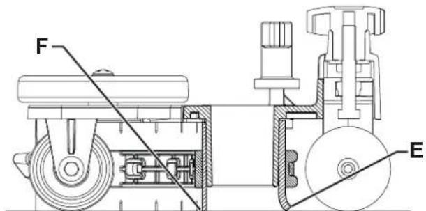
- Wash and clean the squeegee. In particular, clean the compartments (A, Fig. 7) and the vacuum hole (B). Check the condition of the front (C) and rear (D) blades, ensuring there are no cuts and tears; if necessary, replace them as shown below.
- Install the squeegee in the reverse order of removal.
SQUEEGEE BLADE CHECK AND REPLACEMENT
- Clean the squeegee as shown in the previous paragraph.
- Check the condition of the front (C, Fig. 7) and rear (D) blades, ensuring there are no cuts and tears; if necessary, replace them as shown below. Check that the front corner (E) of the rear blade is not worn; otherwise, turn the blade to replace the worn corner with one of the three remaining intact corners. If the other corners are worn too, replace the blade according to the following procedure:
• Using the tab (F), release and remove the elastic strap (G) from the fasteners (H), then turn or replace the rear blade (D).
• Install the rear blade in the reverse order of removal. Fasten the elastic strap (G) to the fasteners (H) starting from one side. To make the fastening procedure easier, secure the fasteners one at a time, by locking the strap before the fastener with one hand (M) and pulling it with the other hand (N).
- Unscrew the handwheels (I) and remove the strap (J), then turn or replace the front blade (C).
• Install the front blade in the reverse order of removal.
- Install the squeegee (29) and screw down the handwheels (14).
- Lower the squeegee to the floor to check the height of the blades, proceeding as follows:
- Check that the lip (K) of the front blade (C) and the lip (L) of the rear blade (D) are resting as shown in the figure.
- Use the knob (15) to make adjustments.
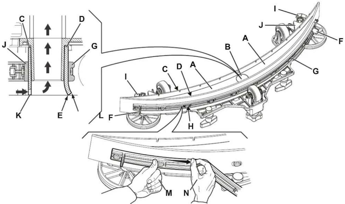
Figure 7
P100955
BRUSH CLEANING

CAUTION!
It is advisable to wear protective gloves when cleaning the brush because there may be sharp debris.
- Remove the brush as shown in Use/Operation chapter.
- Clean the brush with water and detergent.
- Check the condition of the brush bristles, ensuring they are not excessively worn; if necessary, replace the brush.
- When using the pad, check it for wear and replace it if necessary.
RECOVERY TANK CLEANING
- Drive the machine to the appointed disposal area.
- Ensure that the machine is off and the ignition key (41) has been removed (if equipped).
- Drain the water in the tank through the hose (12).
- Raise the cover (34).
- Wash the inside of the tank (33) and the cover with clean water.
- Clean the vacuum grid (31), release the fasteners (A, Fig. 8), open the grid (B) and recover the float (C) then clean it carefully and reinstall it.
- Remove the debris collection tank (D) and open its cover, then clean it carefully and reinstall it on the vacuum hose.
- Check the condition of the tank cover gasket (E).

NOTE
The gasket (E) allows the creation of a vacuum in the tank, which is necessary to suck up the recovery water.
If necessary, replace the gasket (E) by removing it from its housing (F). When fitting the new gasket, position the joint (G) in the lower area, as shown in the figure.
- Check that the seating surface (H) of the gasket (E) is in good condition, clean and suitable to form a seal with the gasket itself.
- Close the cover (34).
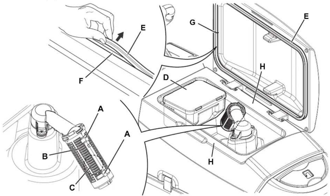
Figure 8
P100956
SOLUTION FILTER CLEANING
- Drive the machine on a level floor.
- Ensure that the machine is off and the ignition key (41) has been removed (if equipped).
- Close the detergent solution tank valve (A, Fig. 9). The valve is closed when it is in position (B) and it is open when it is in position (C).
- Remove the transparent cover (D) and the gasket (E), then remove the filter strainer (F). Wash and rinse them, then refit them carefully onto the filter support (G).
- Open the valve (A).
DETERGENT TANK AND DETERGENT SYSTEM CLEANING
(For machines with Detergent System)
Clean the detergent tank (17) as follows.
- Drive the machine to the appointed disposal area.
- Ensure that the machine is off and the ignition key (41) has been removed (if equipped).
-
Lift the cover (34) and check that the recovery tank (33) is empty; if not, empty it using the drain hose (12).
-
Close the cover (34).
-
Grasp the handle (16) and carefully lift the tank (33).
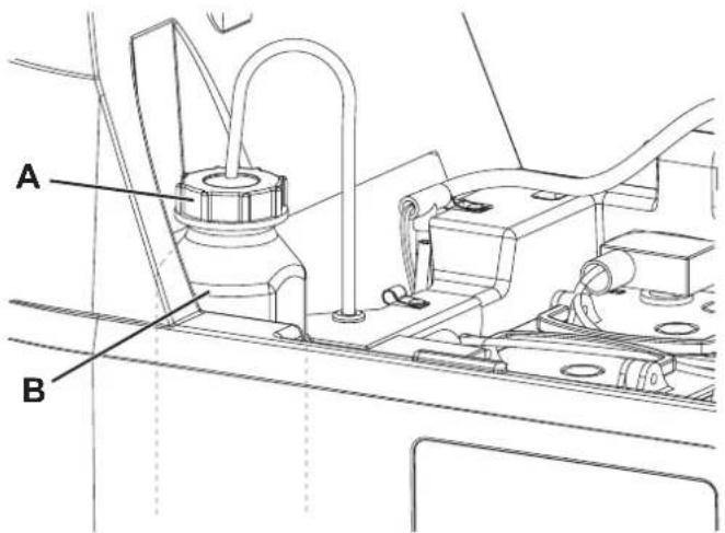
-
Unscrew the cap (A, Fig. 10) from the detergent tank (B).
-
Remove the tank.
-
Rinse and wash out the tank with clean water in the appointed disposal area.

NOTE
For a thorough washing of the Detergent System, the cleaning procedure can also be performed with the detergent tank (17) full of water.
Turn on the system with the flow set to the maximum (see the procedure in Use/Operation chapter). It is advisable to perform this type of cleaning when the Detergent System is dirt/furred up, because the machine has not been used/cleaned for a long time.
- Replace the detergent tank (B) as shown in the figure, then refit the plug (A).
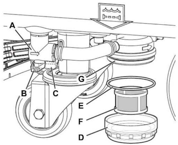
Figure 9
P100957

Figure 10
P100958
FUSE CHECK/REPLACEMENT

NOTE
All machine electrical circuits are protected by auto-resettable electronic devices. The safety fuses activates only in case of serious damage.
It is recommended to have the fuses replaced by qualified personnel only.
Refer to the Service Manual available at any Nilfisk Retailer.
TROUBLESHOOTING
| TROUBLE POSSIBLE CAUSE | REMEDY | |
| The motors are not operating; the button LEDs do not turn on. | The battery connector is disconnected. Connect. | |
| The batteries are completely discharged. Charge the batteries. | ||
| The machine does not move. (Only for drive versions) | The machine is turned on with the ignition key and by keeping the hands on the presence sensors. | Turn the ignition key to “0”, then try to start the machine again with hands off the sensors. |
| The battery symbol LEDs flash simultaneously. | Brush motor overload. | Use less aggressive brushes suitable for the floor to be cleaned. |
| There are foreign materials (tangled threads, etc.) preventing the brush from rotating. | Clean the brush hub. | |
| The scrubbing/drying function does not start. The control panel is broken. Replace. (*) | ||
| The dirty water vacuuming is insufficient. | The recovery tank is full. Empty the tank. | |
| The vacuum grid is clogged or the float is stuck closed. | Clean the vacuum grid. | |
| Debris collection filter container clogged. Clean | ||
| The hose is disconnected from the squeegee. Connect. | ||
| The squeegee is dirty or the squeegee blades are worn or damaged. | Clean the squeegee or overturn/replace the blades. | |
| The tank cover is not properly closed, or the gasket is damaged. | Correctly close the cover or clean/replace the gasket. | |
| The vacuum system does not work and the vacuum system button LED flashes fast. | Vacuum system motor overload. Replace. (*) | |
| The solution flow to the brush is insufficient. | Empty detergent solution tank. | Refill. |
| The solution filter is dirty. | Clean the filter. | |
| The Detergent System (optional) or the tank is dirty/furred up. | Clean with the washing cycle. | |
| The squeegee leaves marks on the floor. | There is debris under the squeegee blades. | Remove the debris. |
| The squeegee blades are worn, chipped or torn. | Overturn or replace the blades. | |
| The squeegee has not been balanced with the handwheel. | Adjust the squeegee. | |
(*) This maintenance procedure must be performed by an authorised Nilfisk Service Center.

NOTE
If the machine has an optional battery charger installed, the machine cannot operate if the charger is not on board. In case of battery charger malfunction, contact an authorised Service Center.
For any further information, contact Nilfisk Service Centres.
SCRAPPING
Have the machine scrapped by a qualified scraper.
Before scrapping the machine, remove and separate the following materials, which must be disposed of properly according to the Law in force:
- Batteries
- Brushes
– Plastic hoses and components - Electrical and electronic components (*)
(*) Refer to the nearest Nilfisk Center especially when scrapping electrical and electronic components.
Machine material composition and recyclability
| Type Recyclable | percentage | Weight % |
| Aluminium 100 % 5 % | ||
| Electric motors - various 29 % 29 % | ||
| Ferrous materials 100 % 8 % | ||
| Wiring harness 80 % 3 % | ||
| Liquids 100 % 0 % | ||
| Plastic - non-recyclable material 0 % 1 % | ||
| Plastic - recyclable material | 100 % 6 % | |
| Polyethylene | 92 % 46 % | |
| Rubber | 20 % 2 % |
INHOUDSOPGAVE
INLEIDING 2
DOEL EN INHOUD VAN DEZE HANDLEIDING....2
BETREFFENDE PERSONEN 2
OPBERGEN VAN DE HANDLEIDING....2
CONFORMITEITSVERKLARING 2
IDENTIFICATIEGEGEVENS 2
ANDERE GEBRUIKERSHANDLEIDINGEN....2
VERVANGINGSONDERDELEN EN ONDERHOUD 2
MODIFICATIES EN VERBETERINGEN....3
BEDRIJFSCAPACITEIT 3
ALGEMENE OPMERKINGEN....3
VERPAKKING VERWIJDEREN/AFLEVERING 3
VEILIGHEID 3
SYMBOLEN OP DE MACHINE 3
SYMBOLEN IN DE HANDLEIDING....4
ALGEMENE INSTRUCTIES 4
BESCHRIJVING VAN DE MACHINE 6
OPBOUW VAN DE MACHINE....6
BEDIENINGSPANEL 8
ACCESSOIRES / OPTIES....9
P100944
P100945
BEDIENINGSPANEEEL
P100946
ACCESSOIRES / OPTIES
- LET OP!
- WAARSCHUWING
- ADVIES
Afbeelding 2
P100949
Afbeelding 3
P100951
natural_image
Top-down line drawing of a car on a grid background with a gray arrow indicating direction (no text or symbols)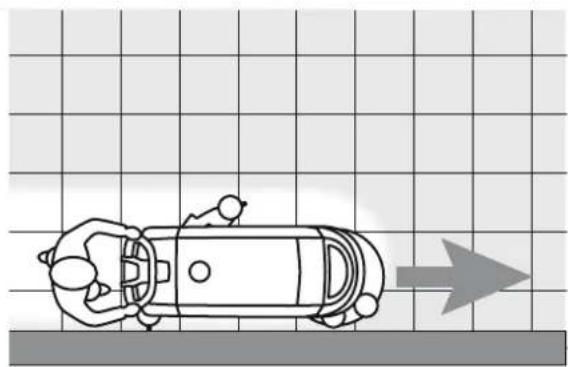
natural_image
Top-down line drawing of a car on a road with a directional arrow (no text or symbols)Afbeelding 5
P100953

WAARSCHUWING!
Afbeelding 7
P100955
REINIGING VAN DE BORSTEL

WAARSCHUWING!
Afbeelding 8
P100956
REINIGING VAN HET FILTER VAN HET REINIGINGSMIDDEL
Afbeelding 9
P100957
Afbeelding 10
P100958
CONTROLE/VERVANGING VAN DE ZEKERINGEN

OPMERKING


- Instructions for use
- SCHALTTAFEL
- HINWEIS!
- BÜRSTE REINIGEN
- DÉBALLAGE / LIVRAISON....3
- SÉCURITÉ 3
- DESCRIPTION DE LA MACHINE 6
- CARACTÉRISTIQUES TECHNIQUES 9
- UTILISATION/FONCTIONNEMENT 11
- ENTRETIEN 18
- DÉPISTAGE DES PANNES....23
- MISE À LA FERRAILLE 24
- INTRODUCTION
- REMARQUE
- CONSERVATION DU MANUEL
- DÉCLARATION DE CONFORMITÉ
- STRUCTURE DE LA MACHINE
- STRUCTURE DE LA MACHINE (suite)
- TABLEAU DE BORD
- ACCESSOIRES / OPTIONS
- AVERTISSEMENT!
- NETTOYAGE DE LA BROSSE
- NETTOYAGE DU FILTRE DE LA SOLUTION
- CONTRÔLE / REMPLACEMENT DES FUSIBLES
- MACHINE DESCRIPTION 6
- TECHNICAL DATA 9
- USE/OPERATION 11
- MAINTENANCE 18
- TROUBLESHOOTING 23
- SCRAPPING 24
- MANUAL PURPOSE AND CONTENTS
- TARGET
- HOW TO KEEP THIS MANUAL
- DECLARATION OF CONFORMITY
- IDENTIFICATION DATA
- OTHER REFERENCE MANUALS
- SPARE PARTS AND MAINTENANCE
- CHANGES AND IMPROVEMENTS
- CONVENTIONS
- UNPACKING/DELIVERY
- SAFETY
- VISIBLE SYMBOLS ON THE MACHINE
- WARNING!
- SYMBOLS THAT APPEAR ON THIS MANUAL
- DANGER!
- CAUTION!
- NOTE
- CONSULTATION
- GENERAL INSTRUCTIONS
- MACHINE DESCRIPTION
- MACHINE STRUCTURE
- MACHINE STRUCTURE (Continues)
- CONTROL PANEL
- ACCESSORIES/OPTIONS
- WIRING DIAGRAM
- (\*) Optional for BASIC versions
- USE/OPERATION
- BATTERY CHECK/SETTING ON A NEW MACHINE
- Batteries already installed on the machine
- Without batteries
- BATTERY INSTALLATION AND SETTING (WET OR GEL)
- Battery Installation
- Battery type setting
- Battery Charging
- BEFORE MACHINE START-UP
- Brush or pad-holder installation
- Brush or pad-holder removal
- Squeegee installation
- Solution tank filling
- (For machines without Detergent System)
- (For machines with Detergent System)
- Detergent tank filling (For machines with Detergent System)
- STARTING UP THE MACHINE (SCRUBBING/DRYING)
- Adjusting of detergent concentration in the washing water
- Battery discharge during operation
- STOPPING THE MACHINE
- TANK EMPTYING
- Recovery tank emptying
- Solution tank emptying
- AFTER USING THE MACHINE
- MACHINE LONG INACTIVITY
- MAINTENANCE
- Preliminary operations
- Charging the Batteries with an External Battery Charger
- Battery charging with battery charger installed on the machine
- SQUEEGEE CLEANING
- SQUEEGEE BLADE CHECK AND REPLACEMENT
- BRUSH CLEANING
- RECOVERY TANK CLEANING
- SOLUTION FILTER CLEANING
- DETERGENT TANK AND DETERGENT SYSTEM CLEANING
- FUSE CHECK/REPLACEMENT
- SCRAPPING
- INHOUDSOPGAVE
- INLEIDING 2
- VERPAKKING VERWIJDEREN/AFLEVERING 3
- VEILIGHEID 3
- BESCHRIJVING VAN DE MACHINE 6
- BEDIENINGSPANEEEL
- ACCESSOIRES / OPTIES
- WAARSCHUWING!
- REINIGING VAN DE BORSTEL
- REINIGING VAN HET FILTER VAN HET REINIGINGSMIDDEL
- CONTROLE/VERVANGING VAN DE ZEKERINGEN
- OPMERKING
Brand : NILFISK
Model : SC401
Category : Scrubber