USER MANUAL SC351 NILFISK
03/2013 Revised 11/2014
(3)
9099864000
Deutsch
Français
English
Nederlandst
Model:
9087340020 - 9087341020 - 9087346020
CeptnuKaT 3a CbOTBETCTBnE
Osvedceni o shode
Konformitatserklarung
Overensstemmelsescertifikat
Declaracion de conformidad
Vastavussertifikaat
Declaration de conformite
Yhdenmukaisuustodistus
Conformity certificate
PiToToiTikO OuMOpPomega
MegeleLoSSegi nyilatkozat
Potvrda sukladnosti
Dichiarazione di conformità
Atitikties deklaracija
Atbilstbas deklaracija
Konformitetssertifisering
Conformiteitsverklaring
Declaracao de conformidade
Deklaracja zgodnosci
Certificat de conformitate
3aBHeNeO COOTBeTCTBnU
Överensstammelsecertifikat
Certifikát suladu
Certifikat o ustreznosti
Uyumluk tertifikasi
CE
Moden / Model / Modell / Model / Modelo / Madel / Modèle / Malli / Model / Movélo / Modell / Model / Modello / Modelis / Modelis / Modell / Model / Modelo / Model / Model / Modèle / Modell / Model / Model :
SC351
Tun / Typ / Typ / Type / Tipo / Tüüp / Type / Typpi / Type / Türoç / Tipus / Vrsta / Tipo / Tipas / Tips / Type / Type / Tipo / Typ / Tip / Tün / Typ / Typ / Tip :
SCRUBBER-DRYER
CepneH Homep / Vyrobni cislo / Seriennummer / Seriennummer / Numero de série / Seerianumber / Numero de série / Sarjanumero / Serial number / Σεπιακός αριθούς / Sorozatszám / Serijski broj /Numero di série / Serijos numris / Serijas numurs / Seriennummer / Seriennummer / Numero de série / Numer seryjny / Numar de série / CepnHbH Homep / Seriennummer / Vyrobné cislo / Serijska stevilka / Seri Numarasi :
ToiHa npOn3BODCTBO / Rok vroby / Baujahr / Fabrikationsar / Ano de fabrication / Valjalaskaaasta / Annee de fabrication / Valmistusvuosi / Year of construction / EtoC katoKeuç / Gyartasi év / Godina izgradnje / Anno di costruzione / Pagaminimo metai / Izgatavosanas gads / Byggear / Bauwjaar / Ano de fabrio / Rok produkci / Anul fabricajei / Tog Bbinycka / Tillverkningsar / Rok vroby / Leto izdelave / Leto izdelave/lmal yli :

IOnyNoDnMCAnHrT NOBbpxkDaBa,Ye
RoepcnoMeHnatm RoMEn E npO3BeDeH B
CbOtBeTCTBne CbC nEHNHTe DnpeKTHNBu
N CTaDapn.TexHvHecknT PaiN e
CbctABeHOT pON3BODnten.

The undersigned certify that the above mentioned model is produced in accordance with the following directives and standards. The technical file is compiled by the manufacturer.

O katwI UTOyEvpaMpEvoc TIOToTIOeiOt n Tnpayavyn Tou TPOAvaepbEvtoc MovTeau yivetaluHpUvaTpeTcakAoOeC oNeyiec KAI pOttua To kExVko apExio Ouvtaoetai ano tv KATAKeuaatn.

GERÄT IN BETRIEB (WISCHEN/TROCKNEN)
CONSERVATION DU MANUEL 2
DECLARATION DE CONFORMITE 2
DONNÉES D'IDENTIFICATION 2
STRUCTURE DE LA MACHINE 6
GUIDON AVEC TABLEAU DE BORD 7
ACCESSORIES / OPTIONS 7
CHARACTERISTIQUES TECHNIQUES 8
SCHEMA ELECTRIQUE 9
UTILISATION 10
CONTROLE / PREPARATION DE LA BATTERIE SUR UNE MACHINE NEUVE 10
INSTALLATION DE LA BATTERIE 10
AVANT LA MISE EN MARCHE DE LA MACHINE 11
MISE EN MARCHE ET ARRÉT DE LA MACHINE 12
MACHINE AU TRAVAIL (LAVAGE / SECHAGE) 12
TRANSPORT / STATIONNEMENT DE LA MACHINE 13
VIDANGE DES RÉSERVOURS 14
APRÈS L'UTILISATION DE LA MACHINE 15
INACTIVITE PROLONGEE DE LA MACHINE 15
ENTRETIEN 15
PLAN D'ENTRETIEN PROGRAMME 15
CHARGEMENT DE LA BATTERIE 16
RéGLAGE DE L'AVANCE DE LA MACHINE 16
NETTOYAGE DE L'EMBOUCHURE 17
CONTROLE ET REMPLACEMENT DES LAMELLES EN CAOUTCHOUC DE L'EMBOUCHURE 17
NETTOYAGE DE LA BROSSE 18
NETTOYAGE DES RESERVOIRS, DU COUVERCLE ET DE LA GRILLE D'ASPIRATION 18
NETTOYAGE DES JOINTS DU SYSTÉME D'ASPIRATION 18
CONTROLE / REMPLACEMENT / RETABILSSEMENT DES FUSIBLES 19
DEPISTAGE DES PANNES 20
MISE A LA FERRAILLE 20
INTRODUCTION

REMARQUE
CONSERVATION DU MANUEL
STRUCTURE DE LA MACHINE
ACCESSIONS / OPTIONS
MANUAL PURPOSE AND CONTENTS 2
TARGET 2
HOW TO KEEP THIS MANUAL 2
DECLARATION OF CONFORMITY 2
IDENTIFICATION DATA 2
OTHER REFERENCE MANUALS 2
SPARE PARTS AND MAINTENANCE 3
CHANGES AND IMPROVEMENTS 3
SYMBOLS THAT APPEAR ON THIS MANUAL 4
GENERALINSTRUCTIONS 4
MACHINE DESCRIPTION 6
MACHINE STRUCTURE 6
HANDLEBAR WITH CONTROL PANEL 7
ACCESSIONS/OPTIONS 7
TECHNICAL DATA 8
WIRING DIAGRAM 9
USE 10
BATTERY CHECK/SETTING ON A NEW MACHINE 10
BATTERY INSTALLATION 10
BEFORE MACHINE START-UP 11
MACHINE START AND STOP 12
MACHINE OPERATION (SCRUBBING/DRYING) 12
MACHINE TRANSPORT/PARKING 13
TANK EMPTYING. 14
AFTER USING THE MACHINE 15
MACHINE LONG INACTIVITY 15
MAINTENANCE 15
SCHEDULEDMAINETANANCETABLE 15
BATTERY CHARGING 16
MACHINE SPEED ADJUSTMENT 16
SQUEEGEE CLEANING 17
SQUEEGEE BLADE CHECK AND REPLACEMENT 17
BRUSH CLEANING 18
TANK, COVER AND VACUUM GRID CLEANING 18
VACUUM SYSTEM GASKET CLEANING 18
FUSE CHECK/REPLACEMENT/RESET 19
TROUBLESHOOTING 20
SCRAPPING 20
INTRODUCTION

NOTE
The numbers in brackets refer to the components shown in Machine Description chapter.
MANUAL PURPOSE AND CONTENTS
The purpose of this Manual is to provide the operator with all necessary information to use the machine properly, in a safe and autonomous way. It contains information about technical data, safety, operation, storage, maintenance, spare parts and disposal. Before performing any procedure on the machine, the operators and qualified technicians must read this Manual carefully. Contact Nilfisk in case of doubts concerning the interpretation of the instructions and for any further information.
TARGET
This Manual is intended for operators and technicians qualified to perform the machine maintenance.
The operator must not perform procedures reserved for qualified technicians. Nilfisk will not be answerable for damages coming from the non-observation of this prohibition.
HOW TO KEEP THIS MANUAL
The Instructions for use Manual must be kept near the machine, inside an adequate case, away from liquids and other substances that can cause damage to it.
The Declaration of Conformity, supplied with the machine, certifies the machine conformity with the law in force.

NOTE
Two copies of the original declaration of conformity are provided together with the machine documentation.
IDENTIFICATION DATA
The machine serial number and model name are marked on the plate (1).
Product code and year of production are marked on the same plate (Date code: A16, means January 2016).
The machine model year is written also in the declaration of conformity.
This information is useful when requiring machine spare parts. Use the following table to write down the machine identification data.
MACHINE model
PRODUCT code
MACHINE serial number
OTHER REFERENCE MANUALS
Electronic Battery Charger Manual (to be considered as integral part of this Manual)
- Spare Parts List (supplied with the machine)
- Service Manual (that can be consulted at Nilfisk Service Centers)
SPARE PARTS AND MAINTENANCE
All necessary operating, maintenance and repair procedures must be performed by qualified personnel or by Nilfisk Service Centers. Only original spare parts and accessories must be used.
Contact Nilfisk for service or to order spare parts and accessories, specifying the machine model, product code and serial number.
CHANGES AND IMPROVEMENTS
Nilfisk constantly improves its products and reserves the right to make changes and improvements at its discretion without being obliged to apply such benefits to the machines that were previously sold.
Any change and/or addition of accessory must be approved and performed by Nilfisk.
This scrubber-dryer is used to clean (scrubbing and drying) smooth and solid floors, in civil or industrial environment, under safe operation conditions by a qualified operator.
The scrubber-dryer cannot be used for fitted carpet and carpet cleaning.
CONVENTIONS
Forward, backward, front, rear, left or right are intended with reference to the operator's position, that is to say in driving position with the hands on the handlebar (2).
UNPACKING/DELIVERY
To unpack the machine, carefully follow the instructions on the packing.
Upon delivery carefully check that the machine and its packing have not been damaged during transportation. In case of visible damages, keep the packing and have it checked by the carrier that delivered it. Call the carrier immediately to fill in a damage claim.
Please check that the following items have been supplied with the machine:
Technical documents:
- Scrubber-dryer Instructions for use Manual
- Battery Charger Manual
- Scrubber-dryer Spare Parts List
No. 2 lamellar fuses
SAFETY
The following symbols indicate potentially dangerous situations. Always read this information carefully and take all necessary precautions to safeguard people and property.
The operator's cooperation is essential in order to prevent injury. No accident prevention program is effective without the total cooperation of the person responsible for the machine operation. Most of the accidents that may occur in a factory, while working or moving around, are caused by failure to comply with the simplest rules for exercising prudence. A careful and prudent operator is the best guarantee against accidents and is essential for successful completion of any prevention program.
VISIBLE SYMBOLS ON THE MACHINE

WARNING!
Carefully read all the instructions before performing any operation on the machine.
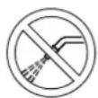
WARNING!
Do not wash the machine with direct or pressurized water jets.
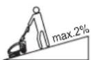
WARNING!
Do not use the machine on slopes with a gradient exceeding the specifications.
SYMBOLS THAT APPEAR ON THIS MANUAL

DANGER!
It indicates a dangerous situation with risk of death for the operator.

WARNING!
It indicates a potential risk of injury for people or damage to objects.

CAUTION!
It indicates a caution or a remark related to important or useful functions. Pay careful attention to the paragraphs marked by this symbol.

NOTE
It indicates a remark related to important or useful functions.

CONSULTATION
It indicates the necessity to refer to the Instructions for use Manual before performing any procedure.
GENERAL INSTRUCTIONS
Specific warnings and cautions to inform about potential damages to people and machine are shown below.

DANGER!
Before performing any cleaning, maintenance, repair or replacement procedure, turn the function selection knob to "0" and disconnect the battery connector.
- This machine must be used by properly trained operators only.
- Do not wear jewels when working near electrical components.
- Do not work under the lifted machine without supporting it with safety stands.
- Do not operate the machine near toxic, dangerous, flammable and/or explosive powders, liquids or vapours: This machine is not suitable for collecting dangerous powders.
- Keep the battery away from sparks, flames and incandescent material. During the normal operation explosive gases are released.
Battery charging produces highly explosive hydrogen gas. Keep the cover open during battery charging and perform this procedure in well-ventilated areas and away from naked flames.

WARNING!
- Carefully read all the instructions before performing any maintenance/repair procedure.
Before using the battery charger, ensure that frequency and voltage values, indicated on the machine serial number plate, match the electrical mains voltage.
- Do not pull or carry the machine by the battery charger cable and never use the battery charger cable as a handle. Do not close a door on the battery charger cable, or pull the battery charger cable around sharp edges or corners. Do not run the machine on the battery charger cable.
- Keep the battery charger cable away from heated surfaces.
- Do not use the machine if the battery charger cable or plug is damaged. If the machine is not working as it should, has been damaged, left outdoors or dropped into water, return it to the Service Center.
To reduce the risk of fire, electric shock, or injury, do not leave the machine unattended when it is plugged in. Before performing any maintenance procedure, disconnect the battery charger cable from the electrical mains.
- Do not smoke while charging the battery.
- Always protect the machine against the sun, rain and bad weather, both under operation and inactivity condition. Store the machine indoors, in a dry place: This machine must be used in dry conditions, it must not be used or kept outdoors in wet conditions.
Before using the machine, close all doors and/or covers as shown in the Instructions for use Manual.

WARNING!
- Use only as shown in this Manual. Use only Nilfisk's recommended accessories.
-
Check the machine carefully before each use, always check that all the components have been assembled before use. If the machine is not perfectly assembled it can cause damages to people and properties.
Take all necessary precautions to prevent hair, jewels and loose clothes from being caught by the machine moving parts.
Pay attention to the machine moving parts. When using the machine, the deck can abruptly turn by 180^ .
-
This machine is not intended for use by persons (including children) with reduced physical, sensory or mental capabilities, or lack of experience and knowledge, unless they have been given supervision or instruction concerning use of the machine by a person responsible for their safety. Children should be supervised to ensure that they do not play with the machine.
- Close attention is necessary when used near children.
-Do not use the machine on incline.
- Do not tilt the machine more than the angle indicated on the machine itself, in order to prevent instability.
- Do not use the machine in particularly dusty areas.
- Use the machine only where a proper lighting is provided.
While using this machine, take care not to cause damage to people or objects.
- Do not bump into shelves or scaffoldings, especially where there is a risk of falling objects.
- Do not lean liquid containers on the machine, use the relevant can holder.
- The machine working temperature must be between 0^ and +40^ .
- The machine storage temperature must be between 0^ and +40^ .
The humidity must be between 30% and 95% .
- When using floor cleaning detergents, follow the instructions on the labels of the detergent bottles.
- To handle floor cleaning detergents, wear suitable gloves and protections.
- Do not use the machine as a means of transport.
- Do not allow the brush to operate while the machine is stationary to avoid damaging the floor.
- In case of fire, use a powder fire extinguisher, not a water one.
- Do not tamper with the machine safety guards and follow the ordinary maintenance instructions scrupulously.
- Do not allow any object to enter into the openings. Do not use the machine if the openings are clogged. Always keep the openings free from dust, hairs and any other foreign material which could reduce the air flow.
- Do not remove or modify the plates affixed to the machine.
- This machine cannot be used on roads or public streets.
Pay attention during machine transportation when temperature is below freezing point. The water in the recovery tank or in the hoses could freeze and seriously damage the machine.
Use brushes and pads supplied with the machine or those specified in the Instructions for use Manual. Using other brushes or pads could reduce safety.
In case of machine malfunctions, ensure that these are not due to lack of maintenance. If necessary, request assistance from the authorised personnel or from an authorised Service Center.
If parts must be replaced, require ORIGINAL spare parts from an Authorised Dealer or Retailer.
To ensure machine proper and safe operation, the scheduled maintenance shown in the relevant chapter of this Manual, must be performed by the authorised personnel or by an authorised Service Center.
- Do not wash the machine with direct or pressurised water jets, or with corrosive substances.
- The machine must be disposed of properly, because of the presence of toxic-harmful materials (battery, etc.), which are subject to standards that require disposal in special centres (see Scrapping chapter).
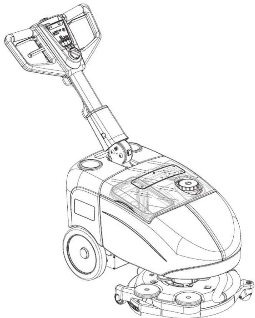
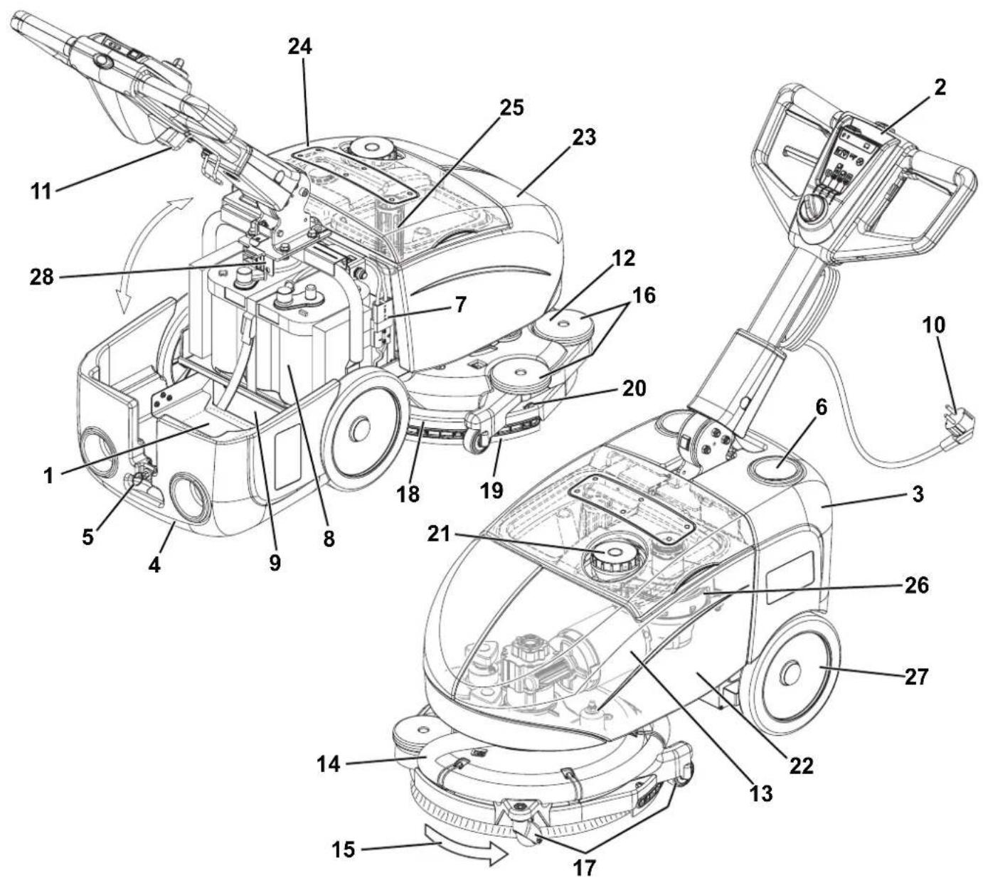
MACHINE DESCRIPTION
MACHINE STRUCTURE
- Serial number plate/technical data/conformity certification
- Handlebar with control panel (see the following paragraph)
- Accessory and battery compartment cover (closed)
- Accessory and battery compartment cover (open)
- Cover latch
- Can holder
- Battery connection connector. This connector also works as EMERGENCY push-button, to stop immediately all functions.
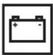
- GEL/AGM battery
- Battery charger
- Battery charger cable
- Battery charger cable holder
- Brush/pad-holder deck
-
Brush deck gearmotor
-
Squeegee vacuum hose
- Brush rotation direction
- Deck bumper wheels
- Brush deck wheels
- Squeegee
- Squeegee blades assembly
- Squeegee fasteners
- Solution tank filler plug
- Solution tank
- Recovery tank
- Transparent cover with vacuum grid
- Vacuum grid with automatic shut-off float
- Vacuum system motor
- Rear wheels on fixed axle
- Fuses
P100404
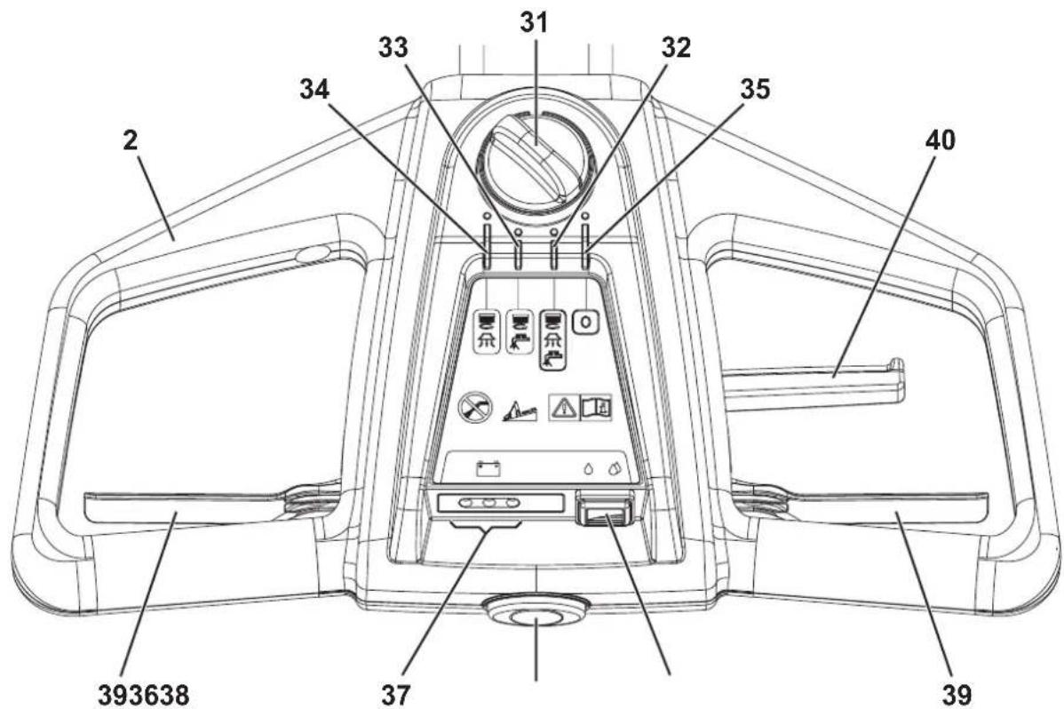
HANDLEBAR WITH CONTROL PANEL
- Function selection knob
- Scrubbing and drying program: brush - vacuum system - solution flow activation
- Scrubbing program: brush - solution flow activation
- Drying program: brush - vacuum system activation
-
Machine switching off "0"
-
Solution flow switch
-
One drop - "ECO" solution flow
-
Two drops - Maximum solution flow
-
Battery charge LED indicators
-
Green warning light - charged battery
Yellow warning light - semi-discharged battery
Red warning light - discharged battery
-
Machine start-up enabling push-button
- Brush levers
- Handlebar inclination adjusting lever
P100405
ACCESSIONS/OPTIONS
In addition to the standard components, the machine can be equipped with the following accessories/options, according to the machine specific use:
- 12V 84AhC5 AGM Battery
Brushes of different materials
- Pads of different materials
For further information concerning the optional accessories, contact an authorised Retailer.
| DESCRIPTION SC351 SC351 full PKG | | |
| Solution tank capacity 11 litres | |
| Recovery tank capacity 11 litres | |
| Machine length 770 mm | |
| Machine width 475 mm | |
| Min/max machine height at the handlebar 550/1,085 mm | |
| Minimum width for turnaround 850 mm | |
| Cleaning width 370 mm | |
| Diameter of wheels on fixed axle 214 mm | |
| Wheel pressure on the floor 0.5 N/mm | 2 |
| Brush/pad diameter 370 mm | |
| Brush/pad pressure on the floor | 18 Kg |
| Brush/pad pressure with full tank | 27 Kg |
| Min/max solution flow | One drop, "ECO": 0.25 litres/minTwo drops: 0.5 litres/min |
| Sound pressure level at workstation (ISO 11201, ISO 4871, EN 60335-2-72) (LpA) | 65 dB(A) ± 3 dB(A) |
| Machine sound power level (ISO 3744, ISO 4871, EN 60335-2-72) (LwA) | 84 dB(A) |
| Vibration level at the operator's arms (ISO 5349-1, EN 60335-2-72) | < 2.5 m/s2 |
| Maximum gradient when working | 2 % |
| IP protection class | X4 |
| Protection class (electric) | III |
| Vacuum system motor power | 200 W |
| Vacuuming | 710 mmH2O |
| Brush/pad-holder motor power | 260 W |
| Brush/pad-holder motor speed | 120 rpm |
| Total absorbed power | 0.5 kW |
| Battery compartment size | 350 x 175 x 240 mm |
| Battery voltage | 12 V |
| Standard battery | - | 12V 55AhC20 AGM spiracell |
| Work autonomy (standard battery) | 1 hour |
| Weight without battery and with empty tanks | 43 kg | 43 kg |
| Gross vehicle weight (GVW) | 80 kg |
| Shipping weight | 48 kg | 70 kg |
| Machine material composition and recyclability |
| Type | Recyclable percentage | SC351 and SC351 full PKG weight percentage |
| Aluminium | 100% | 18% |
| Electric motors - various | 29% | 9% |
| Ferrous materials | 100% | 20% |
| Wiring harness | 80% | 9% |
| Liquids | 100% | 0% |
| Plastic - non-recyclable material | 0% | 11% |
| Plastic - recyclable material | 100% | 18% |
| Polyethylene | 92% | 9% |
| Rubber | 20% | 7% |
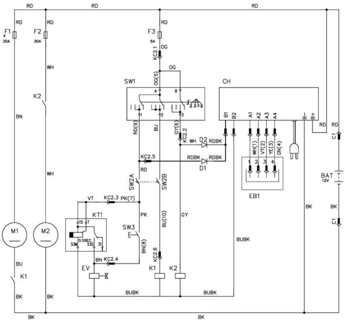
WIRING DIAGRAM
Key
BAT 12 V battery
CH Battery charger
D1 Diode
D2 Diode
EB1 LED electronic board
EV Detergent solenoid valve
F1 Brush motor circuit breaker (35 A)
F2 Vacuum system motor fuse (30 A)
F3 Function selector fuse (5 A)
K1 Brush motor relay
K2 Vacuum system motor relay
KT1 Solenoid valve timer
M1 Brush motor
M2 Vacuum system motor
SW1 Function selector
SW2 Brush motor-solenoid valve enabling switch
SW3 Detergent rate switch
Colour codes
BK Black
BU Blue
BN Brown
GN Green
GY Grey
OG Orahge
PK Pink
RD Red
VT Violet
WH | White
YE Yelloww
P100406
USE

WARNING!
On some points of the machine there are some adhesive plates indicating:
DANGER
-WARNING
-CAUTION
CONSULTATION
While reading this Manual, the operator must pay particular attention to the symbols shown on the plates (see Visible Symbols On The Machine paragraph).
Do not cover these plates for any reason and immediately replace them if damaged.
BATTERY CHECK/SETTING ON A NEW MACHINE

WARNING!
The electric components of the machine can be seriously damaged if the battery is either improperly installed or connected. The battery must be installed by qualified personnel only. Check the battery for damage before installation.
Disconnect the battery connector and the battery charger plug.
Handle the battery with great care.
Install the battery terminal protection caps supplied with the machine.
The machine requires 1 12V battery.
The machine can be supplied in one of the following modes:
GEL/AGM battery already installed on the machine
- Open the cover (4) and check that the battery is connected to the machine with the connector (7).
- Turn the function selection knob (31) on one of the programs to turn on the machine. If the green warning light (37) turns on, the batteries are ready to be used.
- If the yellow or red warning light turns on, the battery must be charged (see the procedure in Maintenance chapter).
Without battery
- Buy appropriate battery (see the Technical Data paragraph).
For battery choice and installation, apply to qualified battery Retailers.
- Install the battery (see the following paragraph).
- Charge the battery (see the procedure in Maintenance chapter).
BATTERY INSTALLATION

DANGER!
This machine requires sealed lead batteries (GEL or AGM technology).
Do not use batteries with liquid electrolyte or not sealed (WET) for any reason.
- Open the cover (4) and check that the battery connector (7) is disconnected.
- Install the battery on the machine and fasten it with the relevant belt.
- Connect the 2 terminals to the battery pins.

WARNING!
Pay special attention when connecting the battery pins. The red cable must be connected to the positive pin (+), the black cable must be connected to the negative pin (-) of the battery.
A wrong connection can damage the battery charger.
- Connect the battery connector (7) and close the cover (4).
- Charge the battery (see the procedure in Maintenance chapter).

WARNING!
The installed battery (GEL/AGM) may require a specific charging algorithm: contact a Nilfisk Service Center to set the charging algorithm suitable to the battery.
BEFORE MACHINE START-UP
Brush/pad-holder installation/removal

NOTE
Install either the brush (A, Fig. 1) or the pad-holder (B and C) according to the type of floor to be cleaned.
- Slightly lift the machine brush deck and place the brush under the deck.
- Turn the function selection knob (31) to program (32).
- Press the enabling push-button (38) together with the brush levers (39) to engage the brush/pad-holder.
Remove the brush/pad-holder deck by performing the following procedure:
4. Check that the function selection knob (31) is turned to "0".
5. Slightly lift the machine brush deck, then manually release the brush/pad-holder from the hub, by turning it abruptly in its normal rotation direction (D).
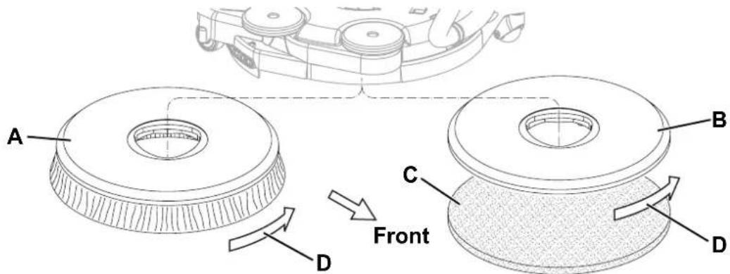
Figure 1
P100407
Available brushes and their relevant application guides (suggestions only)
| Models MIDLITE GRIT 180 MIDGRIT 240 PROLITE UNION MIX | | |
| General cleaning | Concrete | | | | |
| Terrazzo floor | | | | |
| Ceramic tiles/quarrystones | | | | |
| Marble | | | | |
| Vinyl tiles | | | | |
| Rubber tiles | | | | |
| Polishing | Rubber tiles | | | | |
| Marble | | | | |
| Vinyl tiles | | | | |
Solution tank filling
- Open the plug (21) and fill the tank (22) with a solution suitable for the work to be performed. Do not fill the solution tank completely, leave few centimetres from the edge. Always follow the dilution instructions on the label of the chemical product used to prepare the solution. The solution temperature must not exceed 40^ .

CAUTION!
Use only low-foam and non-flammable detergents, intended for automatic scrubber applications.

WARNING!
When using floor cleaning detergents, follow the instructions on the labels of the detergent bottles.
To handle floor cleaning detergents, wear suitable gloves and protections.
Adjustments
- Press the lever (40) and adjust the handlebar (2) to reach a comfortable position.
MACHINE START AND STOP
Starting the machine
- Prepare the machine as shown in the previous paragraph.
- Turn the function selection knob (31) to turn on the machine and select one of the programs according to the following table:
| Position Symbol Program | |
| (32) | scrubbing and drying.
Brush - vacuum system - solution flow activation |
| (33) | scrubbing.
Brush - solution flow activation |
| (34) | Drying.
Brush - vacuum system activation |
- Turn the solution flow control switch (36) to one of the following positions, according to the type of cleaning to be performed:
One drop: to scrub/clean floors which are not very dirty; in this condition the machine can work with an autonomy of 50 minutes (0.25 litres/min average).
- Two drops: to scrub/clean floors which are quite or very dirty; in this condition the machine can work with an autonomy of 25 minutes (0.5 litres/min average).
- While keeping the hands on the handlebar (2), start the machine by pressing the enabling push-button (38) together with the brush levers (39).

NOTE
If the green warning light (37) turns on, the machine is ready to be used. If the yellow or red warning light turns on, the battery must be charged (see the procedure in Maintenance chapter).
Stopping the machine
- Release the brush levers (39) and the enabling push-button (38).
- Turn the function selection knob (31) to "0" to turn off the machine.

CAUTION!
In case of immediate necessity and to stop all machine functions, disconnect the battery connector (7). Reset the machine functions by connecting again the connector.
MACHINE OPERATION (SCRUBBING/DRYING)
- Start the machine as shown in the previous paragraph.
- While keeping both hands on the handlebar (2), move the machine and start scrubbing/drying the floor.
- If necessary, adjust the solution quantity by using the switch (36).
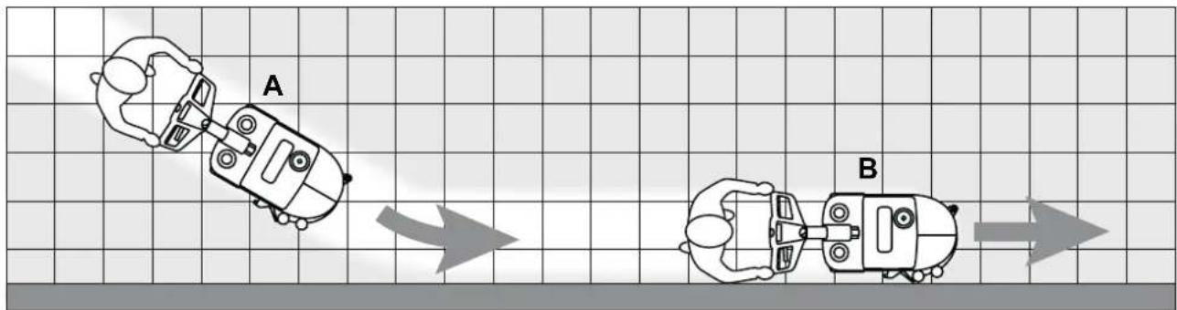
- When necessary, to use the squeegee in the opposite direction, pry on the handlebar (2) and slightly lift the deck while the brush is turning. When the deck is turned by 180^ start to scrub/dry by drawing the machine. To resume working in the normal forward direction, push the machine forward until the brush deck (12) returns to the original position.

WARNING!
Pay attention when lifting the deck with the brush turning: The deck will suddenly turn by 180^ . Pay attention to the moving part, do not hit and/or damage things, walls or people.

CAUTION!
To avoid damaging the floor surface, do not use the brush without the solution and, when the machine is not operating, stop the brush/pad-holder by releasing the levers (39).

CAUTION!
Before lifting the brush/pad, turn it off by releasing the levers (39).

NOTE
For correct scrubbing/drying of floors at the sides of the walls, Nilfisk suggests to go near the walls with the right side of the machine as shown in figure 2.
Figure 2
P1004108
Machine speed adjustment
- The machine speed varies according to the type of floor to be cleaned and the choice of using the brush or the pad. If necessary, it is possible to adjust the machine speed, according to the procedure shown in Maintenance chapter.
Battery discharge during operation
- Until the green warning light (37) stays on, the batteries allow the machine to work normally. When the green warning light turns off and the yellow and red warning lights turn on, it is necessary to charge the battery as the machine residual autonomy is at the minimum level.

CAUTION!
Do not use the machine with discharged battery, to avoid damaging the battery and reducing the battery life.
MACHINE TRANSPORT/PARKING
To transport/park the machine, proceed as follows.
1. Check that the function selection knob (31) is turned to "0".
2. Grab the handlebar (2) and slightly lift the machine brush deck. While holding the machine in this position, drive it to the transport/parking area.
3. When finishing working, it is advisable to remove the brush/pad in order not to drag it on the floor and leave wet marks.
TANK EMPTYING
An automatic float shut-off system (25) turns off the vacuum system when the recovery tank (23) is full.
The vacuum system shutdown is signalled by an increase in the vacuum system motor noise, moreover the floor is not dried.

CAUTION!
If the vacuum system turns off accidentally (for example, when the float is activated because of a sudden machine movement), to resume the operation: turn off the machine with the function selection knob (31) turned to "0", check that the float inside the grid (25) has gone down to the water level. Then turn on the vacuum system by pressing the function selection knob (31).
When the recovery tank (23) is full, empty it as shown.
Recovery tank emptying
- Check that the function selection knob (31) is turned to "0".
- Drive the machine to the appointed disposal area.
- Remove the transparent cover (24).
- Grab the handle (A, Fig. 3) and lift the recovery tank (B).
- Drain the recovery tank. Then, rinse the tank with clean water.
- Place the tank back again on its housing in the frame and install the transparent cover.
Solution tank emptying
- Perform steps 1 to 3.
- Grab the handle (C, Fig. 3) and lift the solution tank (D).
- Open the plug (E) and drain the solution tank. Then, rinse the tank with clean water.
- Place the tank back again on its housing in the frame and install the transparent cover.
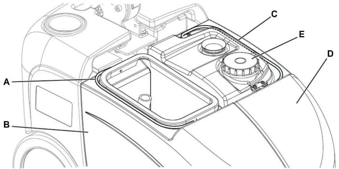
Figure 3
P100409
AFTER USING THE MACHINE
After working, before leaving the machine:
- Empty the tanks (23 and 22) as shown in the previous paragraph.
- Perform the daily maintenance procedures (see the Maintenance chapter).
- Store the machine in a clean and dry place, with the brush/ pad-holder and the squeegee blades lifted or removed.
MACHINE LONG INACTIVITY
If the machine is not going to be used for more than 30 days, proceed as follows:
- Perform the procedures described in the previous paragraph.
- Open the cover (4) and disconnect the battery connector (7).
- Store the machine in a clean and dry place.
- To safeguard the brush or squeezegee blades, bend the handlebar (2) forward and park the machine as shown in figure 4.
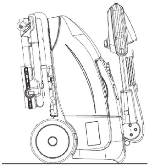
Figure 4
P100410
MAINTENANCE
The lifespan of the machine and its maximum operating safety are ensured by correct and regular maintenance. The following chart provides the scheduled maintenance. The intervals shown may vary according to particular working conditions, which are to be defined by the person in charge of the maintenance.

WARNING!
Maintenance procedures must be performed with the machine switched off and the battery/battery charger cable disconnected.
Moreover, carefully read the instructions in the Safety chapter.
All scheduled or extraordinary maintenance procedures must be performed by qualified personnel, or by an authorised Service Center. This Manual describes only the easier and most common maintenance procedures.

NOTE
For other maintenance procedures shown in the Scheduled Maintenance Table, refer to the Service Manual that can be consulted at any Service Center.
SCHEDULED MAINTENANCE TABLE
| Procedure | Daily, after using the machine | Weekly | Every six months | Yearly |
| Battery charging | | | | |
| Squeegee Cleaning | | | | |
| Brush Cleaning | | | | |
| Tank and Vacuum Grid Cleaning | | | | |
| Squeegee blade check and/or replacement | | | | |
| Solution valve check and cleaning (1) | | | | |
| Brush deck rotation clutch check and/or replacement (1) | | | | |
(1) For the relevant procedure, refer to the Service Manual.
BATTERY CHARGING

NOTE
Charge the batteries when the yellow or red warning light turns on, or at the end of each working cycle. Keeping the battery charged make its life last longer.

CAUTION!
When the battery is discharged, charge is as soon as possible, as that condition makes its life shorter. Check for battery charge at least once a week.
- Drive the machine on a level floor.
- Check that the function selection knob (31) is turned to "0".
- Connect the battery charger cable (10) to the electrical mains (the electrical mains voltage and frequency must be compatible with the battery charger values shown on the machine serial number plate (1)).

NOTE
When the battery charger is connected to the electrical mains, all machine functions are automatically cut off. The red or yellow warning light (37) is on when the battery charger is charging the batteries.
- When the green warning light (37) stays on, the battery charging cycle is over.
- When the battery charging is completed, disconnect the battery charger cable (10) from the electrical mains and wind it round its housing (11).
- Now the machine is ready to be used.

NOTE
For further information about the operation of the battery charger (9), see the relevant Manual.
MACHINE SPEED ADJUSTMENT

NOTE
The machine speed varies according to the type of floor to be cleaned and the choice of using the brush or the pad. If necessary, perform the adjustments as shown.
- Remove the recovery and the detergent tanks.
-
Adjust the machine speed with the handwheel (A, Fig. 5):
-
Turn the handwheel counter-clockwise to increase the machine speed.
-
Turn the handwheel clockwise to decrease the machine speed.
-
If it is difficult to keep the machine moving straight-forwardly because it deviates to the left or to the right, adjust the handwheel (B) by turning it clockwise or counter-clockwise.
- After adjusting, install the tanks as shown in Use chapter.
- With the machine ready to operate, perform hands-on tests of the machine and, if other adjustments are necessary, repeat steps 1 to 4.
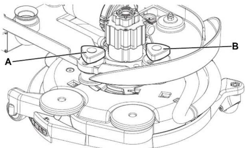
Figure 5
P100413
SQUEEGEE CLEANING

NOTE
The squeegee must be clean and its blades must be in good conditions in order to get a good drying.

WARNING!
It is advisable to wear protective gloves when cleaning the squeegee because there may be sharp debris.
- Drive the machine on a level floor.
- Check that the function selection knob (31) is turned to "0" and disconnect the battery connector (7).
- Fully turn the brush/pad-holder deck (12) counter-clockwise.
- Disconnect the vacuum hose (A, Fig. 6) from the squeegee.
- Disengage the squeegee (B) from the deck.
- Wash and clean the squeegee. In particular, clean the compartments (C) and the vacuum hole (D).
- Check the front blade (E) and the rear blade (F) for integrity, cuts and tears; if necessary replace them (see the procedure in the following paragraph).
- Assemble the components in the reverse order of disassembly.
SQUEEGEE BLADE CHECK AND REPLACEMENT
- Clean the squeegee as shown in the previous paragraph.
-
Check the front blade (E, Fig. 6) and the rear blade (F) for integrity, cuts and tears; if necessary replace them. Check that the front corner (G) of the rear blade is not worn; otherwise, overturn the blade to replace the worn corner with an integral one. If the other corners are worn too, replace the blade as shown:
-
Remove the fastening strap (H) by disengaging it from the fasteners (I).
- Replace (or overturn) the rear blade (F), then reinstall the fastening strap.
- Remove the fastening strap (J) by disengaging it from the fasteners (K).
-
Replace (or overturn) the front blade (E), then reinstall the fastening strap.
-
Install the squeegee (B) by carefully inserting the hooks (L) and the vacuum hole (M) in the brush deck housings.
- Connect the vacuum hose (A) to the squeegee.
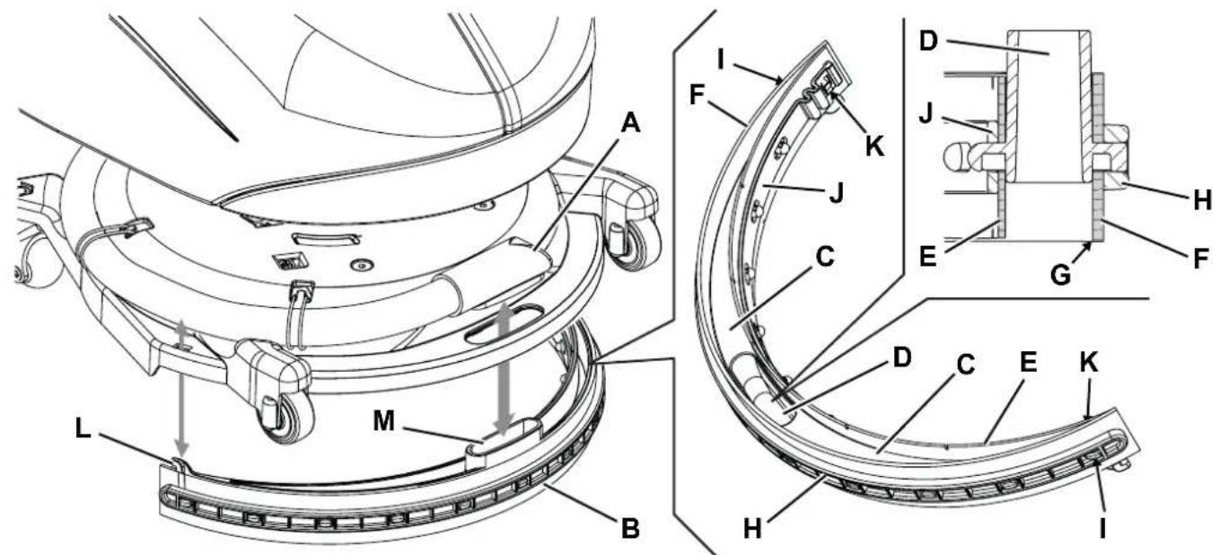
Figure 6
P100411
BRUSH CLEANING

NOTE
It is advisable to wear protective gloves when cleaning the brush because there may be sharp debris.
- Remove the brush, as shown in Use chapter.
- Clean the brush with water and detergent.
- Check the brush bristles for integrity and wear; if necessary, replace the brush.
TANK, COVER AND VACUUM GRID CLEANING
- Drive the machine to the appointed disposal area.
- Check that the function selection knob (31) is turned to "0" and disconnect the battery connector (7).
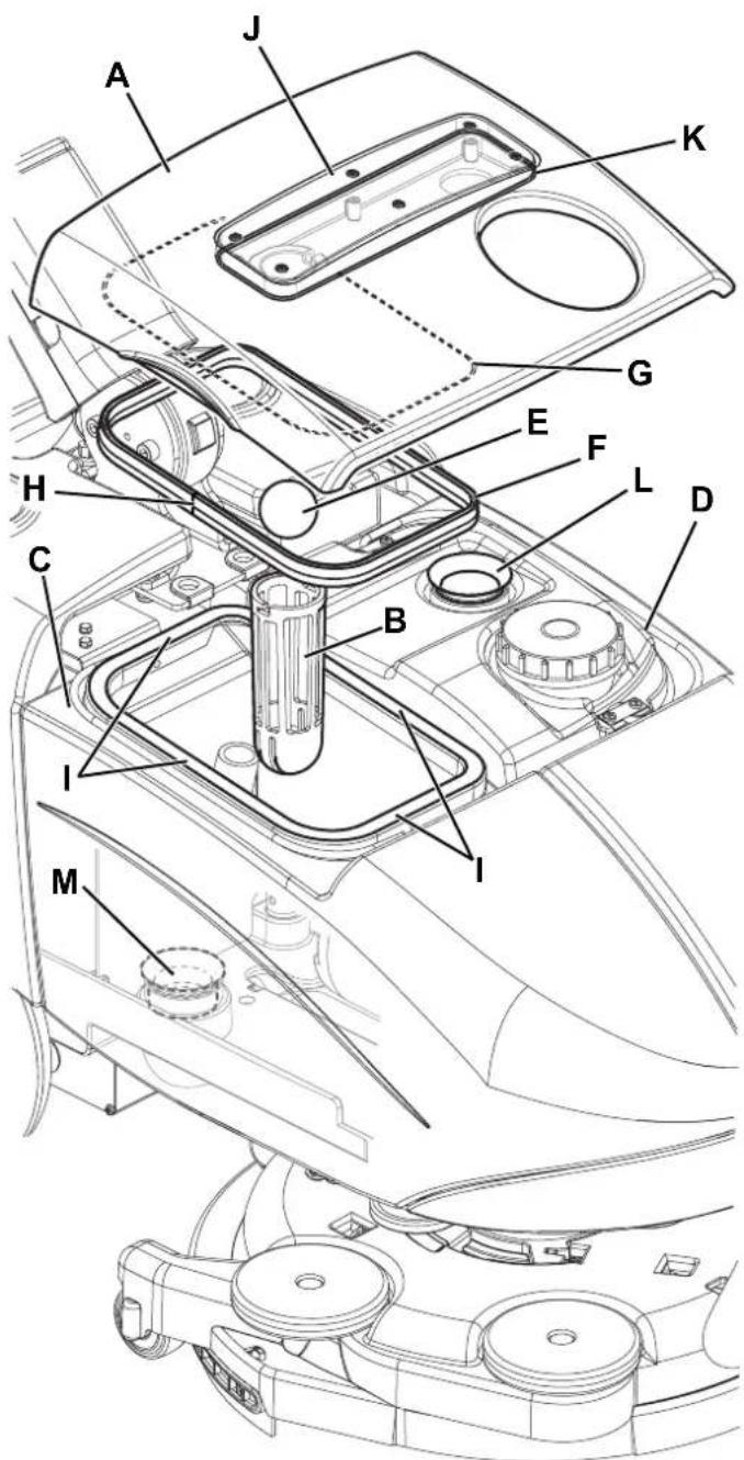
- Remove the cover (A, Fig. 7), clean and wash the cover and the vacuum grid (B) with clean water.
- Drain the water from the tanks (C and D) and clean them.
- If necessary, disassemble the grid (B) and remove the float (E), then clean with care and reinstall.
- Check the recovery tank cover gasket (F) for integrity.

NOTE
The gasket (F) creates vacuum in the tank that is necessary for vacuuming the recovery water.
If necessary replace the gasket (F) by removing it from its housing (G) on the cover. When assembling the new gasket, install the joint (H) in the area shown in the figure.
- Check that the seating surface (I) of the gasket (F) is clean and adequate for the gasket itself.
- Check the vacuum duct (J) and the gasket (K), carefully clean if necessary.
- Reinstall the recovery tank cover (A).
VACUUM SYSTEM GASKET CLEANING

NOTE
The gaskets (L) and (M) create vacuum in the system that is necessary for vacuuming the recovery water.
- Drive the machine on a level floor.
- Check that the function selection knob (31) is turned to "0" and disconnect the battery connector (7).
- Open the cover (A, Fig. 7) and check the vacuum system motor gasket (L) for integrity. If necessary replace the gasket by removing it from its housing.
- Remove the recovery tank (C).
- Check the recovery water duct gasket (M) for integrity. If necessary, replace the gasket.
- Clean with care and reinstall.
Figure 7
P100412
FUSE CHECK/REPLACEMENT/RESET
- Drive the machine on a level floor.
- Check that the function selection knob (31) is turned to "0" and disconnect the battery connector (7).
- Open the cover (4) and check one of the following fuses for deactivation or integrity (Fig. 8):
(A): F1 (35 A) circuit breaker, brush motor.
(B): F2 (30 A) blade fuse, vacuum system motor.
(C): F3 (5 A) blade fuse, accessories.
Reset or replace any fuse, after having checked and repaired any problem that caused deactivation.
- Close the cover (4).
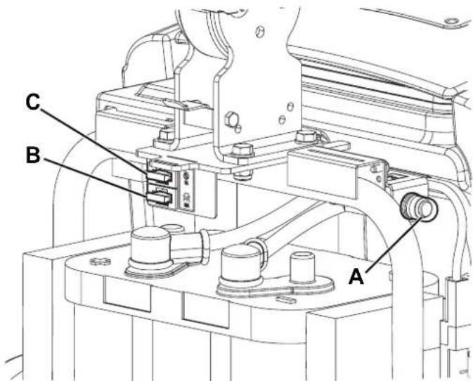
Figure 8
P100414
TROUBLESHOOTING
| Trouble Possible Cause Remedy | | |
| The motors do not turn on; no LED turns on. | The battery connector is disconnected. Connect. | |
| The battery is completely discharged. | Contact Nilfisk Service Center to restore the battery or to replace it. |
| The fuse F3 is open. Replace. | |
| The brush motor does not run. The F1 fuse has triggered. Reset the fuse. | | |
| The vacuum system motor does not turn on. | The fuse F2 is open. Replace. | |
| The dirty water vacuuming is insufficient. | The recovery tank is full. Empty. | |
| The vacuum grid is clogged or the float is stuck closed. | Clean the grid and check the float. |
| The vacuum hose is disconnected from the squeezegee or faulty. | Connect or replace. (*) |
| The squeezegee is dirty or the squeezegee blades are worn or damaged. | Clean the squeezegee or replace the blades. |
| The recovery tank cover is not properly closed, or the gaskets are damaged. | Check and/or clean the seating surface or replace the gaskets. |
| The vacuum system motor filter is dirty. Clean. | |
| The solution flow is insufficient. | The detergent duct is dirty/clogged. Clean. | |
| The solenoid valve is faulty. Replace. (*) | |
| The squeezegee leaves marks on the floor. | There is debris under the squeezegee blades. Remove the debris. | |
| The squeezegee blades are worn, chipped or torn. Replace the blades. | |
| When connecting the battery charger to the electrical mains the 3 LEDs on the handlebar turn on and the battery does not charge. | The battery is damaged or it is excessively discharged. | Contact Nilfisk Service Center to restore the battery or to replace it. |
| When connecting the battery charger to the electrical mains the yellow LED on the handlebar flashes and the battery does not charge. | The battery is not properly connected to the machine system. | Check the battery connections. |
| When connecting the battery charger to the electrical mains the red LED on the handlebar flashes and the battery does not charge. | There is a fault in the battery charger. Replace. (*) | |
| When the battery charging procedure is completed, the red LED on the handlebar flashes. | The battery has not been fully charged during the maximum time interval allowed. | Try to repeat the battery charging procedure. If the problem persists, replace the battery. |
(*) This maintenance procedure must be performed by an authorised Nilfisk Service Center.

NOTE
The machine is inoperative without the battery charger.
In case of battery charger malfunction, contact an authorised Service Center.
For further information refer to the Service Manual, available at any Nilfisk Service Center.
SCRAPPING
Have the machine scrapped by a qualified scraper.
Before scrapping the machine, remove and separate the following materials, which must be disposed of properly according to the
Law in force:
Battery
Brushes
Plastic hoses and components
Electrical and electronic components (^*)
(*) Refer to the nearest Nilfisk Center especially when scrapping electrical and electronic components.
INHOUDSOPGAVE
INLEIDING 2
DOEL EN INHOUD VAN DEZE HANDLEIDING 2
BETREFFENDE PERSONEN 2
OPBERGEN VAN DE HANDLEIDING 2
CONFORMITEITSVERKLARING 2
IDENTIFICATIEGEGEVENS 2
ANDERE GEBRUIKERSHANDLEIDINGEN 2
VERVANGINGSONDERDELEN EN ONDERHOUD 3
MODIFICATIES EN VERBETERINGEN 3
BEDRIJFSCAPACITEIT 3
ALGEMENE OPMERKINGEN 3
VERPAKKING VERWIJDEREN/AFLEVERING 3
VEILIGHEID 3
ACCESSORIES / OPTIES 7
- LET OPI!
WAARSCHUWING
- ADVIES