
DM460T - Wood lathe SCHEPPACH - Free user manual and instructions
Find the device manual for free DM460T SCHEPPACH in PDF.
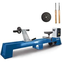
| Product type | Wood lathe |
| Brand | Scheppach |
| Model | DM460T |
| Dimensions (L x W x H) | 940 x 270 x 420 mm |
| Weight | 34,8 kg |
| Supply voltage | 220-240 V~ / 50 Hz |
| Power consumption (P1) | 0,55 kW |
| Output power (P2) | 0,30 kW |
| Rotation speeds | 650 / 1000 / 1450 / 2000 / 3000 rpm |
| Distance between centers | 457 mm |
| Height of centers | 152 mm |
| Diameter over bed | 305 mm |
| Diameter between centers | 240 mm |
| Tool rest width | 150 mm |
| Headstock spindle thread | M33 |
| Headstock spindle taper | MK2 |
| Talstock quill bore | 9,5 mm |
| Sound pressure level (idle) | 61,3 dB(A) |
| Sound power level (processing) | 91,7 dB(A) |
| Protection class | II (double insulation) |
| Operating mode | S1 (continuous) |
| Application | Wood turning |
| Maintenance | Regular cleaning, lubrication of rotating parts, belt inspection |
| Safety equipment | Hearing protection, safety glasses, hairnet, protective covers |
| Wearing parts | Woodturning chisels, carbon brushes, V-belt |
Frequently Asked Questions - DM460T SCHEPPACH
User questions about DM460T SCHEPPACH
0 question about this device. Answer the ones you know or ask your own.
Ask a new question about this device
Download the instructions for your Wood lathe in PDF format for free! Find your manual DM460T - SCHEPPACH and take your electronic device back in hand. On this page are published all the documents necessary for the use of your device. DM460T by SCHEPPACH.
USER MANUAL DM460T SCHEPPACH
natural_image
Mechanical lathe machine labeled 'scheppach' with no visible text or symbols on the device itself| DE | DrechselmaschineOriginalbedienungsanleitung | 5 |
| GB | Wood-turning machineTranslation of original instruction manual | 18 |
| FR | Machine de tournageTraduction des instructions d'origine | 29 |
| IT | TornioTraduzione dalle istruzioni d'uso originali | 41 |
| NL | HoutdraaibankVertaling van originele handleiding | 53 |
| SE | SvarvmaskinÖversättning av original-bruksanvisning | 65 |
| FI | SorvikoneKäännös alkuperäisestä käyttöohjeesta | 76 |
| NO | TredreiebankOversettelse fra original brukermanual | 87 |
| DK | DrejemaskineOversættelse fra den originale brugervejledning | 98 |
| EE | TreimasinTölge Originaalkasutusjuhend | 109 |
| LT | Medžio tekinimo staklėsVertimas originali naudojimo instrukcija | 120 |
| LV | KokvirpaTulkošana no originala lietošanas instrukcija | 131 |
| HR | TokarilicaOriginalni priručnik | 143 |
| SI | Stroj za struženjePrevod iz originalnih navodil za uporabo | 154 |
| CZ | Soustruh na dřevoPřeklad originálního návodu k obsluze | 165 |
| SK | SústruhPreklad originálu návodu na obsluhu | 176 |
| HU | EsztergagépAz eredeti útmutató fordítása | 187 |
| BG | Дърводелски стругПревод на оригиналното ръководство | 199 |
| PL | TokarkaTlumaczenie oryginalnej instrukcji obsługi | 212 |


natural_image
Technical schematic of a mechanical assembly with no visible text or symbols
natural_image
Illustration showing a book with a cross mark and a hand holding a tool on a wooden post (no text or symbols)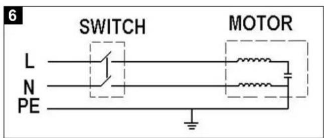
Günzburger Straße 69
D-89335 Ichenhausen
Verehrter Kunde,
Explanation of the symbols on the device
 | Warning! Danger to life, risk of injury or damage to the tool are possible by ignoring! |
 | Before commissioning, read and observe the operating manual and safety instructions! |
 | Wear hearing protection! |
 | Wear a hair net! |
 | Wear safety goggles! |
 | The use of gloves is prohibited! |
 | Protection class II (double shielded) |
Table of contents: Page:
- Introduction......20
- Device description....20
- Scope of delivery 20
- Proper use....20
- Safety instructions....21
- Technical data 23
- Before commissioning....24
- Attachment and operation 24
- Transport 26
- Cleaning and maintenance....26
- Storage....27
- Electrical connection 27
- Disposal and recycling 28
- Troubleshooting....28
1. Introduction
Manufacturer:
scheppach
Günzburger Straße 69
D-89335 Ichenhausen
Dear Customer,
we hope your new tool brings you much enjoyment and success.t.
Note:
In accordance with the applicable product liability laws, the manufacturer of this device assumes no liability for damage to the device or caused by the device arising from:
- Improper handling
- Failure to comply with the operating instructions.
- Repairs carried out by third parties, unauthorised specialists.
- Installing and replacing non-original spare parts,
• Application other than specified - A breakdown of the electrical system that occurs due to the non-compliance of the electric regulations and VDE regulations 0100, DIN 57113 / VDE0113.
We recommend:
Read the whole text of the operating manual before assembly and commissioning.
The operating instructions are intended to help the user to become familiar with the machine and take advantage of its application possibilities in accordance with the recommendations.
The operating instructions contain important information on how to operate the machine safely, professionally and economically, how to avoid danger, costly repairs, reduce downtimes and how to increase reliability and service life of the machine.
In addition to the safety regulations in the operating instructions, you have to meet the applicable regulations that apply for the operation of the machine in your country.
Keep the operating instructions package with the machine at all times and store it in a plastic cover to protect it from dirt and moisture. Read the instruction manual each time before operating the machine and carefully follow its information. The machine can only be operated by persons who were instructed concerning the operation of the machine and who are informed about the associated dangers.
In addition to the safety notes contained in the present operating instructions and the special regulations of your country, the generally recognized technical rules for the operation of woodworking machines must be observed.
We accept no liability for damage or accidents which arise due to non-observance of these instructions and the safety information.
2. Device description
- Headstock
- Face plate
- Tool rest with eccentric clamping and release handle
- Tailstock tip
- Carrier
- Tailstock
- Eccentric release handle (on the back of the tail-stock)
- Wood-turning bed
- On/off switch
- Lever and binding screw
3. Scope of delivery
- Wood-turning machine
- Tool support
- Carrier
- Rotating tailstock centre
- Face plate
- Mandrel
- Tappet
- Jaw spanner SW 32/41
- Hex driver 3/6/8
- Operating manual
4. Proper use
The machine is only designed for working on wood using a suitable turning tool.
The machine meets the currently valid EU machine directive.
The manufacturer's safety, operation and maintenance instructions as well as the technical data given in the calibrations and dimensions must be adhered to.
Relevant accident prevention regulations and other generally recognized safety and technical rules must also be adhered to.
The machine may only be used, maintained or repaired by trained persons who are familiar with the machine and have been informed about the dangers. Unauthorized modifications of the machine exclude a liability of the manufacturer for damages resulting from the modifications.
The machine is intended for use only with original spare parts and original tools from the producer.
Any other use is considered to be not intended. The manufacturer excludes any liability for resulting damages, the risk is exclusively borne by the user.
⚠️ Please note that our equipment has not been designed for use in commercial, trade or industrial applications. Our warranty will be voided if the equipment is used in commercial, trade or industrial businesses or for equivalent purposes.
5. Safety instructions
General power tool safety warnings
⚠ WARNING: Read all safety warnings, instructions, illustrations and specifications provided with this power tool.
Failure to follow all instructions listed below may result in electric shock, fire and/or serious injury.
Save all warnings and instructions for future reference.
The term "power tool" in the warnings refers to your mains-operated (corded) power tool or battery-operated (cordless) power tool.
1. Work area safety
a) Keep work area clean and well lit. Cluttered or dark areas invite accidents.
b) Do not operate power tools in explosive atmospheres, such as in the presence of flammable liquids, gases or dust. Power tools create sparks which may ignite the dust or fumes.
c) Keep children and bystanders away while operating a power tool. Distractions can cause you to lose control.
2. Electrical safety
a) Power tool plugs must match the outlet. Never modify the plug in any way. Do not use any adapter plugs with earthed (grounded) power tools. Unmodified plugs and matching outlets will reduce risk of electric shock.
b) Avoid body contact with earthed or grounded surfaces, such as pipes, radiators, ranges and refrigerators. There is an increased risk of electric shock if your body is earthed or grounded.
c) Do not expose power tools to rain or wet conditions. Water entering a power tool will increase the risk of electric shock.
d) Do not abuse the cord. Never use the cord for carrying, pulling or unplugging the power tool. Keep cord away from heat, oil, sharp edges or moving parts. Damaged or entangled cords increase the risk of electric shock.
e) When operating a power tool outdoors, use an extension cord suitable for outdoor use. Use of a cord suitable for outdoor use reduces the risk of electric shock.
f) If operating a power tool in a damp location is unavoidable, use a residual current device (RCD) protected supply. Use of an RCD reduces the risk of electric shock.
3. Personal safety
a) Stay alert, watch what you are doing and use common sense when operating a power tool. Do not use a power tool while you are tired or under the influence of drugs, alcohol or medication. A moment of inattention while operating power tools may result in serious personal injury.
b) Use personal protective equipment. Always wear eye protection. Protective equipment such as a dust mask, non-skid safety shoes, hard hat or hearing protection used for appropriate conditions will reduce personal injuries.
c) Prevent unintentional starting. Ensure the switch is in the off-position before connecting to power source and/or battery pack, picking up or carrying the tool. Carrying power tools with your finger on the switch or energising power tools that have the switch on invites accidents.
d) Remove any adjusting key or wrench before turning the power tool on. A wrench or a key left attached to a rotating part of the power tool may result in personal injury.
e) Do not overreach. Keep proper footing and balance at all times. This enables better control of the power tool in unexpected situations.
f) Dress properly. Do not wear loose clothing or jewellery. Keep your hair and clothing away from moving parts. Loose clothes, jewellery or long hair can be caught in moving parts.
g) If devices are provided for the connection of dust extraction and collection facilities, ensure these are connected and properly used. Use of dust collection can reduce dust-related hazards.
h) Do not let familiarity gained from frequent use of tools allow you to become complacent and ignore tool safety principles. A careless action can cause severe injury within a fraction of a second.
4. Power tool use and care
a) Do not force the power tool. Use the correct power tool for your application. The correct power tool will do the job better and safer at the rate for which it was designed.
b) Do not use the power tool if the switch does not turn it on and off. Any power tool that cannot be controlled with the switch is dangerous and must be repaired.
c) Disconnect the plug from the power source and/or remove the battery pack, if detachable, from the power tool before making any adjustments, changing accessories, or storing power tools. Such preventive safety measures reduce the risk of starting the power tool accidentally.
d) Store idle power tools out of the reach of children. Do not allow persons unfamiliar with the power tool or these instructions to operate the power tool. Power tools are dangerous in the hands of untrained users.
e) Maintain power tools and accessories. Check for misalignment or binding of moving parts, breakage of parts and any other condition that may affect the power tool's operation. If damaged, have the power tool repaired before use. Many accidents are caused by poorly maintained power tools.
f) Keep cutting tools sharp and clean. Properly maintained cutting tools with sharp cutting edges are less likely to bind and are easier to control.
g) Use the power tool, accessories and tool bits etc. in accordance with these instructions, taking into account the working conditions and the work to be performed. Use of the power tool for operations different from those intended could result in a hazardous situation.
h) Keep handles and grasping surfaces dry, clean and free from oil and grease. Slippery handles and grasping surfaces do not allow for safe handling and control of the tool in unexpected situations.
5. Service
a) Have your power tool serviced by a qualified repair person using only identical replacement parts. This will ensure that the safety of the power tool is maintained.
Warning! This electric tool generates an electromagnetic field during operation. This field can impair active or passive medical implants under certain conditions. In order to prevent the risk of serious or deadly injuries, we recommend that persons with medical implants consult with their physician and the manufacturer of the medical implant prior to operating the electric tool.
Operational Safety Instructions for the Wood Turning Lathe
- Familiarise yourself with the machine's features and wood-turning techniques before using the machine.
-
Examine all workpieces for splits or knots. Glued joints must set completely before turning.
-
Ensure that the workpiece is securely locked in position and all attachments are secured.
- Before turning the machine ON ensure that the workpiece can rotate freely by rotating it by hand.
- Keep your hands and fingers away from the rotating workpiece.
- Switch the machine OFF and wait until it has come to a full stop before making any adjustments on the workpiece, tailstock, or tool rest.
- Maintenance, adjustment, calibration and cleaning may only be performed with the motor turned off.
- The machine is designed for use with wood-turning chisels only.
- Always store away the wood-turning chisels safely before you leave the workplace.
- Do not run the lathe without its covers and guards in place.
- Keep cutting tools sharp.
- Use the lowest speed when starting a new workpiece.
- Always stop the lathe at its slowest speed. If the lathe is run so fast that it vibrates, there is a risk that the workpiece will be thrown or the cutting tool jerked from your hands.
- Do not allow cutting tools to bite into the workpiece. The wood could be split or thrown from the lathe.
- Always position the tool rest above the centre line of the lathe when shaping a piece of stock.
- Before attaching a workpiece to the face plate, always rough it out to make it as round as possible. This minimizes the vibrations while the piece is being turned. Always fasten the workpiece securely to the faceplate. Failure to do so could result in the workpiece being thrown away from the lathe.
- Use a brush or compressed air to remove wood shavings; never your hands. The wood shavings will be sharp.
- The cutting tool must always be tight within the chuck and adjusted to limit projection from the post. This will reduce the possibility of the tool breaking or bending.
- Do not reach a cross the lathe while it is running.
- Only feed workpiece into a cutting tool against the direction of rotation. The workpiece must always be rotating toward you.
- Do not leave the tool unattended when it is plugged into an electrical outlet. Turn off the tool, and unplug it from its electrical outlet before leaving.
- This product is not a toy. Keep it out of reach of children.
- Some dust created by power sanding, sawing, grinding, drilling, and other construction activities, contains chemicals known to cause cancer, birth defects or other reproductive harm. Some examples of these chemicals are:
- Lead from lead-based paints
- Crystalline silica from bricks and cement or other masonry products
- Arsenic and chromium from chemically treated lumber
- Your risk from these exposures varies, depending on how often you do this type of work. To reduce your exposure to these chemicals: work in a well ventilated area, and work with approved safety equipment, such as those dust masks that are specially designed to filter out microscopic particles.
- People with pacemakers should consult their physician(s) before use. Electromagnetic fields inclose proximity to heart pacemaker could cause pacemaker interference or pacemaker failure. In addition, people with pacemakers should:
- Avoid operating alone.
- Properly maintain and inspect to avoid electrical shock.
- The warnings, precautions, and instructions discussed in this user manual cannot cover all possible conditions and situations that may occur. It must be understood by the operator that common sense and caution are factors which cannot be built into this product, but must be supplied by the operator.
Additional safety instructions for the use of face-plates
- Ensure that the faceplate is the appropriate size to support the workpiece.
- Ensure that the workpiece is securely fastened to the faceplate.
- Rough cut the workpiece as close as possible to the final shape before mounting onto a faceplate.
- Only use scraping chisels for faceplate turning. Cutting chisels can easily be torn out of your hands.
- Pay attention that the woodturning chisel cannot interfere with the holding screws at the finished dimensions of the workpiece.
Remaining hazards
The machine has been built using modern technology in accordance with recognized safety rules. Some remaining hazards, however, may still exist.
- Only process selected woods without defects such as: Branch knots, edge cracks, surface cracks. Wood with such defects is prone to splintering and hazardous.
- Wood which is not correctly glued can explode when being processed due to centrifugal force.
- Trim work piece to a rectangular shape, center and correctly secure before processing. Unbalanced work pieces can be hazardous.
-
Injuries can occur when feeding work pieces if tool supports are not correctly adjusted or if turning tools are blunt. Sharp turning tools which are free of defects are necessary for professional turning.
-
Long hair and loose clothing can be hazardous when the work piece is rotating. Wear personal protective gear such as a hair net and tight fitting work clothes.
- Saw dust and wood chips can be hazardous. Wear personal protective gear such as safety goggles and a dust mask.
- The use of incorrect or damaged mains cables can lead to injuries caused by electricity.
- Even when all safety measures are taken, some remaining hazards which are not yet evident may still be present.
- Remaining hazards can be minimized by following the instructions in „Safety Precautions“, „Proper Use“ and in the entire operating manual.
- Before carrying out any adjustment or maintenance work, switch off the device and disconnect the mains plug.
6. Technical data
Dimensions L x B x H mm 940 x 270 x 420
| Bed height mm 190 | |
| Headstock thread M 33 | |
| Headstock taper MK 2 | |
| Height of centers above bed mm | 152 |
| Width between centers mm 457 | |
| Diameter above bed mm 305 | |
| Diameter between centers mm | 240 |
| Length of tool holder mm 150 | |
| Weight kg | 34,8 |
| Wood turning spindle with dust-proof precision grooved ball bearing | |
| Speed rpm | 650 / 1000 / 1450 / 2000 / 3000 |
| Tailstock | |
| Tailstock cone | MK 2 |
| Tailstock drill hole (hollow spindle) ø mm | 9,5 |
| Tailstock sleeve adjustment mm | 47 |
| Drive | |
| Electric motor | 220 – 240V~ / 50 Hz |
| Input P1 kW | 0,55 |
| Power output P2 kW | 0,30 |
| Speed rpm | 1400 |
| Motor protection | yes |
| Undervoltage release | yes |
Combination switch/plug Mains plug
Operating mode S1
* Operating mode S1, continuous operation
Noise level
The noise levels have been determined in accordance with EN 62841.
| Sound pressure level (Idling) L_pA | 61,3 dB(A) |
| Sound pressure level (Operating) L_pA | 78,7 dB(A) |
| Uncertainty K_pA | 3 dB |
| Sound power level (Idling) L_WA | 74,3 dB(A) |
| Sound power level (Operating) L_WA | 91,7 dB(A) |
| Uncertainty K_WA | 3 dB |
Technical changes reserved!
Wear hearing protection.
Excessive noise can result in a loss of hearing. Total vibration values (vector sum - three directions) determined in accordance with EN 62841.
7. Before commissioning
- Open the packaging and carefully remove the device.
- Remove the packaging material, as well as the packaging and transport safety devices (if present).
- Check whether the scope of delivery is complete.
- Check the device and accessory parts for transport damage.
- If possible, keep the packaging until the expiry of the warranty period.
ATTENTION
The device and the packaging are not children's toys! Do not let children play with plastic bags, films or small parts! There is a danger of choking or suffocating!
- The machine must be securely installed, i.e. bolted down on a workbench, base frame or similar.
- Prior to commissioning, all covers and safety devices must be mounted correctly.
- In case of previously machined wood, be aware of any foreign bodies, such as nails or screws, etc.
- Before connecting the machine, check that the data on the type plate matches those of the mains system.
- The machine must only be connected to a properly installed safety socket which is protected by a fuse of at least 16A.
8. Attachment and operation
⚠ Warning! Danger of injury!
Prepare the workplace where you intend to place the electrical power tool. Provide enough space to ensure safe and trouble-free operation. The power tool is designed for working in enclosed rooms and has to be installed on level and firm ground.
⚠️ Important! Pull out the power plug before carrying out any maintenance, resetting or assembly work on the device!
Prior to commissioning, observe the safety instructions in the operating instructions.
Remove the tensioning spindle or the chuck from the spindle in addition to any step-up tools before first operating the machine!
Speed adjustment
The speed can only be adjusted once the machine has been unplugged.
The correct number of revolutions is visible on the speed diagram located on the headstock. The speed diagram is intended for medium-hard dry woods.
The appropriate speed is based on various factors such as:
- type and composition of woods
- seasoned, dry woods
• diameter and length of workpieces
• squared or unbalanced woods
• width of pre-worked, balanced workpieces - wood turner tools and technique
• workpieces out of glued wood
Successful wood turning does not result from high speeds, but rather, from correct use of the machine.
Guidelines for speed adjustment
Low speeds for:
• workpieces with large diameters
- hard workpieces with large diameters
- long, unbalanced workpieces
- glued pieces of wood
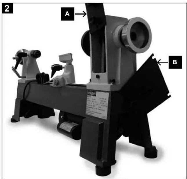
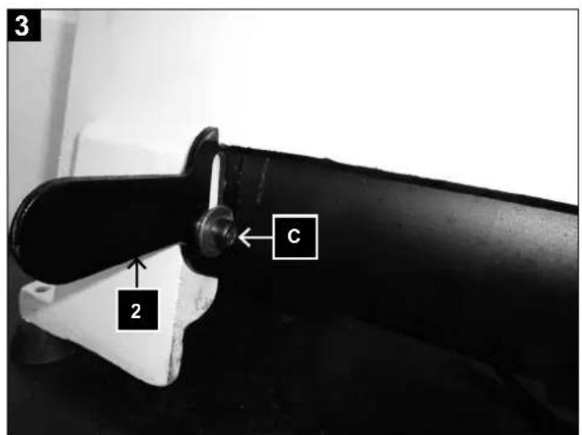
Speed adjustment, Fig. 2+3
- Open casing by rotating the lock screw of a revolution to the left.
- Loosen the socket-head screw (C).
- Using the lever, raise the electric motor and move the belt to the desired level. The belt must lie exactly in the grooves of the belt disc.
- Lower the electric motor into place and tighten the belt by applying light pressure to the lever (2). Tighten the socket-head screw (C).
NOTE
Extremely high belt-tension causes rapid wear of the belt.
- Close the casing and lock into place by turning the screw of a revolution to the right.
- When working with highly unbalanced workpieces, select a speed at least one level lower.
Driver, Fig. 1, 5
The driver is used exclusively for work between both centers.
Face plate, Fig. 1, 2
The face plate is used with flat larger tools.
Change of the clamping tools
- Loosen grub screw on the shaft of the clamping tool.
- Retain spindle with mandrel, release the clamping tool with the hexagonal spanner.
Tailstock, Fig. 1, 6
- Once the eccentric clamp has been loosened, the tailstock can be moved over the entire length of the bed and can be secured at any distance from the headstock.
- To insert a workpiece between the centers, loosen the binder, turn the sleeve approx. 20 mm outward and clamp.
- Slide the tailstock to the workpiece and place the tailstock center into the sunken point in the center of the workpiece.
- Screw out the tailstock sleeve until the tailstock center rests securely in the wood. Retighten the binder.
- Turn the workpiece to see if it rests securely between the two centers and can be rotated freely.
Tailstock center replacement, Fig. 1, 4
- Turn tailstock spindle sleeve totally backwards until the tip can be removed.
Tool holder, Fig. 1, 3
- The tool holder both insures safe use of wood turning tools and at the same time serves as a support for the hand. The height of the tool holder can be adjusted once the binder has been loosened. To turn further, pull in the direction indicated by the arrow.
- Place the tool holder at a distance of 1 – 3 mm from the workpiece. Check the adjustment in addition to rotating the workpiece by hand.
-
Set the tool holder ca. 3 mm above the axis of the workpiece. Check the adjustment once again by rotating the workpiece by hand.
-
Once the eccentric clamp has been loosened, the holder console can be moved along the entire length of the bed and in the direction perpendicular to the workpiece. Furthermore, the holder console can be tilted over approx. 45^ to either side.
- To work with a plane surface, turn the tool holder 90^ and place up against the surface to be worked. Depending on the wood turning tool, place the tool holder up to 6 mm underneath the axis of the workpiece.
Use of wood turning tools, Fig. 4
Examples of how to use the tools when working with the most frequent forms. Once the machine has been plugged in, it is ready to be used. Observe the operating instructions in „Electrical connection“.
Switching on and off, Fig. 1
- Press the On switch (9/„I“) to start the machine.
- Press the Off switch (9/“0”) to stop the machine.
Caution: The device starts running immediately at the set speed.
Speed adjustment, Fig. 1
The correct speed must be set to suit the workpiece to be processed.
Important information for operation
- We recommend that you refer to specialised literature on wood-turning techniques.
- Look out for knots and shrinkage shakes when selecting the wood for your turning work. Only use wood which is free of cracks and large knots (where there are small knots, take appropriate care with the pressure applied with the turning tool).
- Always check that the shaped item is securely held by checking it by hand. Warning! Pull out the power plug!
- Use only an original turning tool which is sharp.
- Do not stand in the flight path of the workpiece when turning wooden disks.
- Please cut large and imbalanced shaped items to size as best as possible using a bandsaw or fret-saw. If the shaped items are very imbalanced they will pose a risk to your health and to the service life of the machine.
- Always start with the lowest possible speed for new workpieces being turned and increase it with increasing massiveness of the workpiece being turned.
- Do not use wooden disks with contraction cracks, since they pose a high risk of bursting under the impact of centrifugal forces.
- Do not exceed the maximum workpiece sizes.
-
In case of tools which get blocked: Pull out the power plug first before starting troubleshooting.
-
To do your turning work, position yourself at the machine so that you can guide the cutting tools effectively on the tool support.
- Only use cutting tools, which are recommended for wood turning works.
Working instructions
A perfect and sharp wood turner tool is a precondition for professional wood-turning.
Selection of materials
- Wood to be turned must be of good quality and without imperfections such as fissures against the grain, a marred surface, or knots. Faulty wood tends to split and becomes a risk for both the operator and the machine.
- Workpieces that have been glued together should only be processed by experienced craftsmen. Because the workpiece can explode as a result of developing centrifugal force, turning such wood demands careful gluing without weak points.
Note: Beginners should first master fundamental skills by working exclusively with solid material.
Preparation of the materials
- To turn long pieces of wood, the material must be cut into a square form beforehand.
- To turn a cross-arm, the material must be cut to size in its natural state as well. Saw out the rough form with a band saw. An octagonal form is recommended for the material so that vibrations are reduced.
Centering of the workpiece, Fig. 5
Centering the prepared workpiece is an important operation to be performed before placing it into the machine. Centering consists of measuring the middle point of the workpiece and marking it with a center punch. Make a depression of 1.5 to 2 mm in the middle point. If the workpiece has not been centered exactly, strong vibrations will develop as a result of the imbalance. It is possible that the workpiece could be hurled outward as a result.
NOTE: Exact centering of the workpiece produces smooth concentricity.
While working with the turner
- Work with a rough workpiece should be conducted at low speeds. Only after the wood has been pre-turned (the pre-turning operation is complete once the basic form of the workpiece as well as an even concentricity have been achieved) can the speed be raised.
TURN OFF AND UNPLUG THE MOTOR FIRST
- The live center must be readjusted from time to time with the hand wheel. This operation only should be performed when the motor has been turned off.
- The tailstock center should rest firmly in the wood.
- Turn the workpiece by hand to check if it rests secured.
Marking of the workpiece
Sometimes the workpiece has to be taken out before it has been completed. It is advantageous to mark the workpiece and the driver with a pencil first.
When placing the workpiece back in the machine, match the marks on the workpiece and the driver.
Specialized literature
Specialized shops offer appropriate specialized literature about wood turning. They can be a great help for beginners in their work as well as a source of ideas for experts.
9. Transport
- Always switch off the electrical tool before transport and disconnect it from the power supply.
- Always carry the electric tool with at least one other person. Carry the power tool to the machine bed (8).
- Protect the electrical tool from impacts, shocks and severe vibrations, e.g. during vehicular transport.
- Secure the electric tool against toppling and slipping.
- Never use protective devices for handling or transport.
10. Cleaning and maintenance
⚠ Warning!
Pull out the mains plug before carrying out any adjustments, maintenance or repair work!
General maintenance tasks
Wipe swarf and dust off the machine from time to time with a cloth. Oil the rotating parts once monthly to extend the life of the tool. Do not oil the motor.
Do not use corrosive agents for cleaning the plastic.
- All protective and safety equipment must be reassembled immediately after repair, maintenance is completed.
- Clean and lightly oil the spindle thread of the tool holder when changing tools.
-
When possible, the tail stock sleeve should be removed by unscrewing it, cleaned and then sprayed with a dry lubricant. Grease the threaded spindle.
-
Check the eccentric clamp of the tailstock as well as the tool holder and adjust if necessary. In addition, tighten the hex nut under the bracket.
- Check the drive belt and replace when necessary.
Maintenance
The device has no further internal parts that require maintenance.
Service information
With this product, it is necessary to note that the following parts are subject to natural or usage-related wear, or that the following parts are required as consumables.
Wear parts*: wood turning chisel, Carbon brushes, v-belt
* may not be included in the scope of supply!
Special accessories
Article Item no.
Turning lathe extension 4902301701
Additional tools 5er set 88002716
Additional tools 6er set 88002717
Screw chuck 7400 7200
Socket chuck ∅ 30 mm 7400 8600
Socket chuck ∅ 40 mm 7400 7300
Socket chuck ∅ 60 mm 7400 8700
Driver plate ∅ 80 mm 7400 8800
Three-jaw chuck ∅ 100 mm 7400 8900
Four-jaw chuck ∅ 125 mm 7400 7400
Drill chuck 3 – 16 mm
cone mandrel MK-2 7400 7700
You can find other accessories in our current catalogue or at www.scheppach.com.
11. Storage
Store the device and its accessories in a dark, dry and frost-proof place that is inaccessible to children. The optimum storage temperature is between 5 and 30°C.
Store the electrical tool in its original packaging.
Cover the electrical tool in order to protect it from dust and moisture.
Store the operating manual with the electrical tool.
12. Electrical connection
The electrical motor installed is connected and ready for operation. The connection complies with the applicable VDE and DIN provisions. The customer's mains connection as well as the extension cable used must also comply with these regulations.
Important information
In the event of overloading, the motor will switch itself off. After a cool-down period (time varies) the motor can be switched back on again
Damaged electrical connection cable
The insulation on electrical connection cables is often damaged.
This may have the following causes:
- Pressure points, where connection cables are passed through windows or doors.
- Kinks where the connection cable has been improperly fastened or routed.
- Places where the connection cables have been cut due to being driven over.
- Insulation damage due to being ripped out of the wall outlet.
- Cracks due to the insulation ageing.
Such damaged electrical connection cables must not be used and are life-threatening due to the insulation damage.
Check the electrical connection cables for damage regularly. Ensure that the connection cables are disconnected from electrical power when checking for damage.
Electrical connection cables must comply with the applicable VDE and DIN provisions. Only use connection lines labelled with H05VV-F.
The printing of the type designation on the connection cable is mandatory.
AC motor
- The mains voltage must be 220 - 240 V\~.
- Extension cables up to 25 m long must have a cross-section of 1.5 mm2.
Connections and repair work on the electrical equipment may only be carried out by electricians.
Please provide the following information in the event of any enquiries:
- Type of current for the motor
• Machine data - type plate
• Machine data - type plate
13. Disposal and recycling
The device is supplied in packaging to avoid transport damages.
This packaging is raw material and can thus be used again or can be reintegrated into the raw material cycle. The device and its accessories are made of different materials, such as metals and plastics.
Take defective components to special waste disposal sites. Check with your specialist dealer or municipal administration!
Old devices must not be disposed of with household waste!

This symbol indicates that this product must not be disposed of together with domestic waste in compliance with the Directive (2012/19/EU) pertaining to waste electrical and onic equipment (WEEE).
This product must be disposed of at a designated collection point. This can occur, for example, by handing it in at an authorised collecting point for the recycling of waste electrical and electronic equipment. Improper handling of waste equipment may have negative consequences for the environment and human health due to potentially hazardous substances that are often contained in electrical and electronic equipment. By properly disposing of this product, you are also contributing to the effective use of natural resources. You can obtain information on collection points for waste equipment from your municipal administration, public waste disposal authority, an authorised body for the disposal of waste electrical and electronic equipment or your waste disposal company.
14. Troubleshooting
| Trouble Possible cause Solution | ||
| Quality of cut is poor. Cutting | tool is dull. Sharpen or replace cutting tool. | |
| Cutting too aggressive cut. Reduce the working pressure. | ||
| Cutting tool is positioned below work-piece center line. | Lower cutting tool to maximum 3mm above the centre line of workpiece. | |
| Lathe speed too slow Increase lathe speed | ||
| Excessive vibration when turning thin workpieces. | Cutting tool is positioned below work-piece centre line. | Raise cutting tool to centerline of workpiece. |
| Cutting to aggressively. Use a lighter touch. | ||
| Excessive vibration when turning large workpieces or bowls. | Headstock and/or tailstock improperly located at ends of workpiece. | Check for proper workpiece centres at head-stock and/or tailstock. |
| Workpiece is unbalanced. Trim end of workpiece until workpiece is more balanced. | ||
| Lathe will not turn on. Cord | not connected into electrical outlet. | Connect to electrical outlet. |
| Lathe will not turn off. Damaged or faulty power switch and/or internal wiring. | Unplug the lathe from its electrical outlet immediately. Do not operate lathe until it is repaired by a qualified service technician. | |
| Motor does not start | No electricity | Check fuse |
| Defective switch, condenser | Have an electrician inspect unit | |
| Defective extension cord | Unplug cord, inspect and replace, if necessary | |
| Work piece flatters while working | Working piece becomes loose while working | Follow the instructions in the operating manual |
| Work piece is not properly centered | Follow the instructions in the operating manual | |
| Excessive speed | Select a lower rotational speed | |
| Tool rest or tailstock cannot be clamped | Setting the eccentric clamping | Return the hexagonal nut at the bottom side about 1⁄2 rotation with the socket spanner |
Günzburger Straße 69
D-89335 Ichenhausen
Cher client,
Günzburger Straße 69
D-89335 Ichenhausen
Egregio cliente,
Günzburger Straße 69
D-89335 Ichenhausen
Geachte klant,
Günzburger Straße 69
D-89335 Ichenhausen
Bästa Kund!
Günzburger Straße 69
D-89335 Ichenhausen
Arvoisa asiakas
Günzburger Straße 69
D-89335 Ichenhausen
Kjære kunde,
Trebucket chuck ∅ 125 mm
7400 7400
Chuck 3 - 16 mm kjegleformet dor MK 2
Du kan finne mer tilbehør i vår aktuelle katalog eller på www.scheppach.com.
11. Lagring
Günzburger Straße 69
D-89335 Ichenhausen
Kære kunde,
Günzburger Straße 69
D-89335 Ichenhausen
Austatud klient!
Günzburger Straße 69
D-89335 Ichenhausen
Gerbiamas kliente,
Günzburger Straße 69
D-89335 Ichenhausen
Godātais klient!
Günzburger Straße 69
D-89335 Ichenhausen
Poštovani kupci,
Günzburger Straße 69
D-89335 Ichenhausen
Spoštovani kupec,
želimo vam veliko veselja in uspeha pri delu z vašo novo napravo.
Napotek:
Günzburger Straße 69
D-89335 Ichenhausen
Vážený zákazníku,
Günzburger Straße 69
D-89335 Ichenhausen
Vážený zákazník,
Günzburger Straße 69
D-89335 Ichenhausen
Kedves Ügyfelünk!
Günzburger Straße 69
D-89335 Ichenhausen
Уважаеми клиенти,
Günzburger Straße 69
D-89335 Ichenhausen
Szanowny Kliencie,
CE - Declaration of Conformity
| 2014/29/EU | 2004/22/EC | 89/686/EC_96/58/EC | 2000/14/EC_2005/88/EC | ||||
| 2014/35/EU | 2014/68/EU | 90/396/EC | |||||
| X | 2014/30/EU | X | 2011/65/EU* | ||||
 | Annex V | ||||||
| Annex VINoise: measured L_WA = xx dB(A); guaranteed L_WA = xx dB(A)P = xx KW; L/∅ = cmNotified Body:Notified Body No.: | |||||||
| Annex IVNotified Body:Notified Body No.:Certificate No.: | 2010/26/EC | ||||||
| Emission. No: | |||||||
Standard references:
EN 62841-1:2015; EN ISO 12000:2010; EN 55014-1:2006+A1+A2; EN 55014-2:2015; EN 61000-3-2:2014; EN 61000-3-3:2013
This declaration of conformity is issued under the sole responsibility of the manufacturer.
Apparent defects must be notified within 8 days from the receipt of the goods. Otherwise, the buyeris rights of claim due to such defects are invalidated. We guarantee for our machines in case of proper treatment for the time of the statutory warranty period from delivery in such a way that we replace any machine part free of charge which provably becomes unusable due to faulty material
or defects of fabrication within such period of time. With respect to parts not manufactured by us we only warrant insofar as we are entitled to warranty claims against the upstream suppliers. The costs for the installation of the new parts shall be borne by the buyer. The cancellation of sale or the reduction of purchase price as well as any other claims for damages shall be excluded.
Garantie FR


- Verehrter Kunde,
- Table of contents: Page:
- Introduction
- Manufacturer:
- scheppach
- Dear Customer,
- Note:
- We recommend:
- Device description
- Scope of delivery
- Proper use
- Safety instructions
- General power tool safety warnings
- Work area safety
- Electrical safety
- Personal safety
- Power tool use and care
- Service
- Operational Safety Instructions for the Wood Turning Lathe
- Additional safety instructions for the use of face-plates
- Remaining hazards
- Technical data
- Noise level
- Technical changes reserved!
- Wear hearing protection.
- Before commissioning
- ATTENTION
- Attachment and operation
- ⚠ Warning! Danger of injury!
- ⚠️ Important! Pull out the power plug before carrying out any maintenance, resetting or assembly work on the device!
- Prior to commissioning, observe the safety instructions in the operating instructions.
- Speed adjustment
- Guidelines for speed adjustment
- Speed adjustment, Fig. 2+3
- NOTE
- Driver, Fig. 1, 5
- Face plate, Fig. 1, 2
- Change of the clamping tools
- Tailstock, Fig. 1, 6
- Tailstock center replacement, Fig. 1, 4
- Tool holder, Fig. 1, 3
- Use of wood turning tools, Fig. 4
- Switching on and off, Fig. 1
- Caution: The device starts running immediately at the set speed.
- Speed adjustment, Fig. 1
- Important information for operation
- Working instructions
- A perfect and sharp wood turner tool is a precondition for professional wood-turning.
- Selection of materials
- Preparation of the materials
- Centering of the workpiece, Fig. 5
- While working with the turner
- TURN OFF AND UNPLUG THE MOTOR FIRST
- Marking of the workpiece
- Specialized literature
- Transport
- Cleaning and maintenance
- ⚠ Warning!
- General maintenance tasks
- Maintenance
- Service information
- Special accessories
- Storage
- Electrical connection
- Important information
- Damaged electrical connection cable
- AC motor
- Please provide the following information in the event of any enquiries:
- Disposal and recycling
- Old devices must not be disposed of with household waste!
- Troubleshooting
- Cher client,
- Egregio cliente,
- Geachte klant,
- Bästa Kund!
- Arvoisa asiakas
- Kjære kunde,
- Lagring
- Kære kunde,
- Austatud klient!
- Gerbiamas kliente,
- Godātais klient!
- Poštovani kupci,
- Spoštovani kupec,
- Napotek:
- Vážený zákazníku,
- Vážený zákazník,
- Kedves Ügyfelünk!
- Уважаеми клиенти,
- Szanowny Kliencie,
- CE - Declaration of Conformity
- Standard references:
- Garantie FR
Brand : SCHEPPACH
Model : DM460T
Category : Wood lathe