
Lata 7.0v - Wood lathe SCHEPPACH - Free user manual and instructions
Find the device manual for free Lata 7.0v SCHEPPACH in PDF.

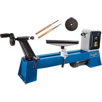
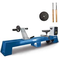
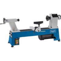
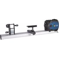
| Product type | Wood lathe |
| Brand | Scheppach |
| Model | Lata 7.0v |
| Dimensions (L x W x H) | 2060 x 500 x 1200 mm |
| Weight | 190 kg |
| Supply voltage | 230–240 V / 50 Hz |
| Power consumption (P1) | 1.5 kW |
| Power output (P2) | 1.1 kW |
| Rotation speed | 0–1200 / 1200–3200 rpm (2 stages) |
| Distance between centers | 1200 mm |
| Height of centers above bed | 230 mm |
| Diameter over bed | 460 mm |
| Diameter between centers | 350 mm |
| Spindle head thread | M33 |
| Tool rest width | 355 mm |
| Circular faceplate (diameter) | 152 mm |
| Tailstock taper | MK2 |
| Tailstock bore | 10 mm |
| Quill adjustment | 110 mm |
| Motor protection | Yes |
| Low-voltage trip device | Yes |
| Operating mode | S6 40% |
| Sound power level (idle) | LWA = 81.9 dB(A) |
| Sound pressure level (idle) | LpAeq = 72.4 dB(A) |
| Included accessories | Tool rest, drive center, rotating tailstock center, tightening rod, faceplate, mounting tool |
| Maintenance | Clean and lubricate tool rest thread, check belts, clean tailstock quill |
| Safety | Stop and unplug before maintenance, wear safety glasses, respect appropriate speed |
| Wear parts | Carbon brushes, V-belt |
| Warranty | Legal duration, defective parts replaced free of charge |
Frequently Asked Questions - Lata 7.0v SCHEPPACH
User questions about Lata 7.0v SCHEPPACH
0 question about this device. Answer the ones you know or ask your own.
Ask a new question about this device
Download the instructions for your Wood lathe in PDF format for free! Find your manual Lata 7.0v - SCHEPPACH and take your electronic device back in hand. On this page are published all the documents necessary for the use of your device. Lata 7.0v by SCHEPPACH.
USER MANUAL Lata 7.0v SCHEPPACH
natural_image
Mechanical lathe machine with levers and a control panel (no visible text or symbols on the device itself)Lata 7.0v
| D | DrechselmaschineOriginal-Anleitung |
| GB | Wood turner latheTranslation from the original instruction manual |
| FR | Tour à boisTraduction des instructions d'origine |
| I | TornioTraduzione dalle istruzioni d'uso originali |
| NL | DraaibankmachineVertaling van originele handleiding |
| SE | SvarvÖversättning av original-bruksanvisning |
| FIN | PuusorviKäännös alkuperäisestä käyttöohjeesta |
| NO | TredreiebenkOversettelse fra original brukermanual |
| DK | VedhoggerOversættelse fra den originale brugervejledning |
| CZ | Soustruh na dřevoPřeklad originálního návodu k obsluze |
| SK | SústruhPreklad originálu návodu na obsluhu |
| HU | EsztergagépAz eredeti útmutató fordítása |
DE

Nur für EU-Länder.
Only for EU countries.
Do not dispose of electric tools together with household waste material! In observance of European directive 2012/19/EU on wasted electrical and electronic equipment and its implementation in accordance with national law, electric tools that have reached the end of their life must be collected separately and returned to an environmentally compatible recycling facility
FR

natural_image
Exterior view of a rectangular concrete pallet with visible bolts and a label, labeled 'Fig. 2' in the top-left corner (no other text or symbols)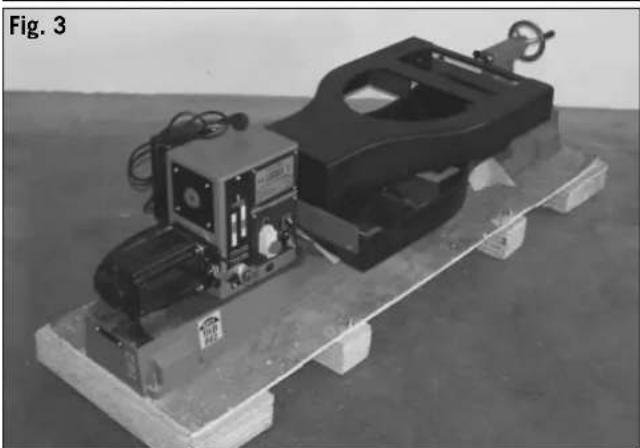
natural_image
Mechanical device on a wooden platform, featuring a black frame and control panel (no visible text or symbols)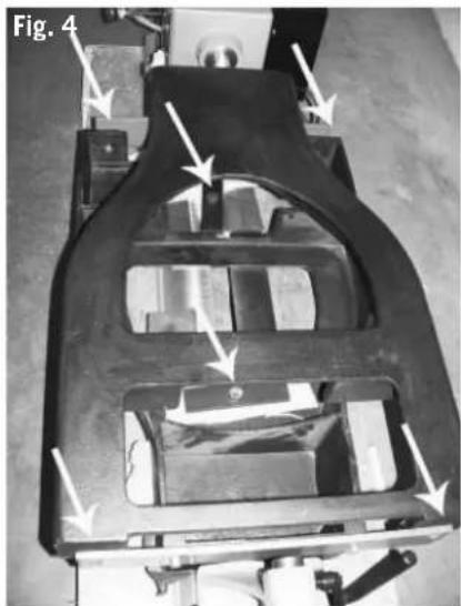
natural_image
Mechanical assembly diagram showing a frame-like component with arrows indicating motion or force direction (no text or symbols present)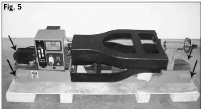
natural_image
Mechanical assembly with a black frame and control panel on a wooden platform, labeled Fig. 5 (no visible text or symbols)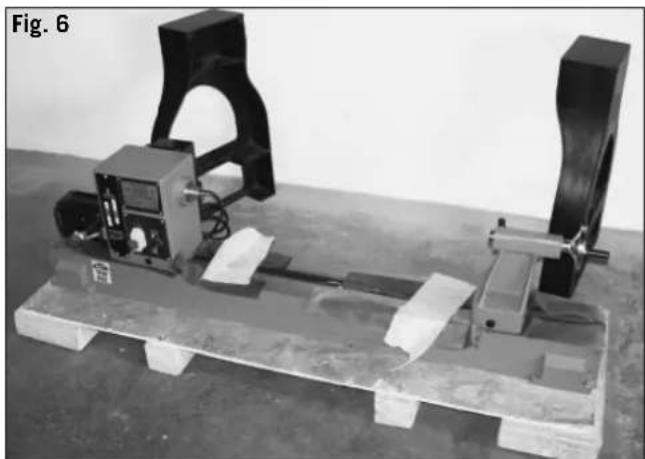
natural_image
Experimental setup with mechanical components mounted on a wooden pallet (no visible text or symbols)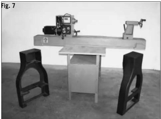
natural_image
Black-and-white photo of a workbench with metal frame and two support chairs, no visible text or symbols.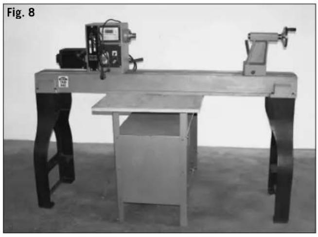
natural_image
Workbench with metal frame and mechanical equipment, labeled Fig. 8 (no visible text or symbols on the equipment)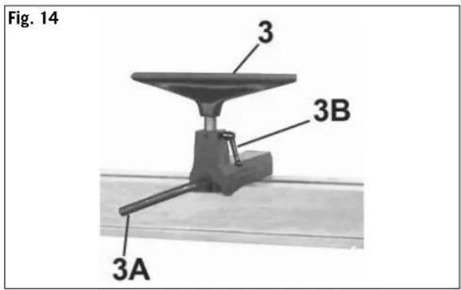
natural_image
Close-up of a mechanical device with black and white components, labeled Fig. 18 (no visible text or symbols on the device itself)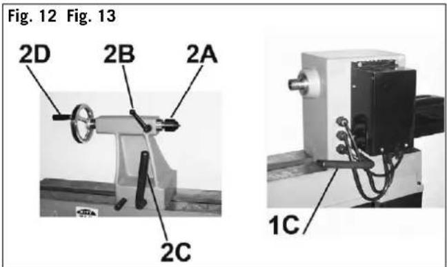
natural_image
Mechanical assembly component labeled Fig. 19, showing a cylindrical pin and bracket (no text or symbols on the main structure)Hersteller:
Scheppach
Günzburger Straße 69
D-89335 Ichenhausen
Verehrter Kunde,
Günzburger Straße 69
D-89335 Ichenhausen
Dear customer,
We wish you much pleasure and success with your new scheppach machine.
Note
In accordance with valid product liability laws, the manufacturer of this device shall not be responsible for damage to and from this device which results from:
- Improper care
• Noncompliance with the Operating Instructions.
• Repairs made by unauthorized persons. - The installation and use of any parts which are not original scheppach replacement parts.
- Improper use and application.
- Failure the electrical system as a result of noncompliance with the legal and applicable electrical directives and VDE regulations 0100, DIN 57113 / VDE 0113.
We recommend
that you read through the entire operating instructions before putting into operation.
These operating instructions are to assist you in getting to know your machine and utilize its proper applications.
The operating instructions contain important notes on how you work with the machine safely, expertly, and economically, and how you can avoid hazards, save repair costs, reduce downtime and increase the reliability and service life of the machine.
In addition to the safety requirements contained in these operating instructions, you must be careful to observe your country's applicable regulations.
The operating instructions must always be near the machine. Put them in a plastic folder to protect them from dirt and humidity. They must be read by every operator before beginning work and observed conscientiously. Only persons who have been trained in the use of the machine and have been informed of the various dangers may work with the machine. The required minimum age must be observed.
In addition to the safety requirements contained in these operating instructions and your country's applicable regulations, you should observe the generally recognized technical rules concerning the operation of woodworking machines.
General notes
- After unpacking, check all parts for any transport damage. Inform the supplier immediately of any faults.
- Later complaints cannot be considered.
• Make sure the delivery is complete. - Before putting into operation, familiarize yourself with the machine by carefully reading these instructions.
- Use only original scheppach accessories, wearing or replacement parts. You can find replacement parts at your scheppach dealer.
- When ordering, include our item number and the type and year of construction of the machine.
| Lata 7.0v | |
| Included with delivery | |
| Wood turner lathe | |
| Tool holder | |
| Driver | |
| Live tailstock center | |
| Tensioning spindle | |
| Face plate | |
| Mid. top | |
| Assembly tools | |
| Operating instructions | |
| Technical data | |
| Dimensions L x B x H mm | 2060 x 500 x 1200 |
| Bed height mm | 920 |
| Headstock thread | M33 |
| Height of centers above bed mm | 230 |
| Width between centers mm | 1200 |
| Diameter above bed mm | 460 |
| Diameter between centers mm | 350 |
| Length of tool holder mm | 355 |
| Face plate ø mm | 152 |
| Weight kg | 190,0 |
| Wood turning spindle with dust-proof precision grooved ball bearing | |
| Revolutions 1/min | 0–12001200–3200 |
| Tailstock | |
| Tailstock cone | MK2 |
| Tailstock drill hole (hollow spindle) ø mm | 10 |
| Tailstock sleeve adjustment mm | 110 |
| Drive | |
| Electric Motor | 230–240V/50 Hz |
| Input P1 kW | 1,5 |
| Output P2 kW | 1,1 |
| Revolutions 1/min | 1400 |
| Motor protection | yes |
| Undervoltage release | yes |
| Switch - plug combination | Netzstecker |
| Operating mode | S6 40% |
Subject to technical modifications!
Noise parameters
The noise emission values at the work place, determined according to EN 23746 (acoustic power levels) and EN 31202 (acoustic pressure levels) with a correction factor k3 calculated according to appendix A.2 of EN 31204, based on operating conditions listed in ISO 7904, appendix A, are:
Acoustic power level in dB
Acoustic pressure level in dB
Idling L_nAeq = 72.4 dB(A)
Operating L_nAen = 76.2 dB(A)
A measuring uncertainty coefficient (K = 4 dB) applies to the emission values listed above.
Controls and features (Fig. 1.1)
1 Headstock
2 Face-plate
3 Carrier
4 Clamp lever for headstock
5 Tailstock
6 Live centre
7 Clamp lever for tool spindle
8 Clamp lever for headstock
9 Adjustment wheel for barrel
10 Tool support
11 Clamp lever for tool support
12 Clamp lever for height adjustment
13 Tool console
14 Lathe bed
15 Feet
General Safety Notes
In these operating instructions we have marked the places that have to do with your safety with this sign.
- Please pass on safety notes and instructions to all those who work on the machine.
- Comply with all safety instructions and warnings on the machine.
- Keep all safety instructions and warnings on the machine fully legible.
- Check all power supply lines. Do not use defective lines.
- Make sure that the machine stands stable on firm ground.
- Caution when working: There is a danger to fingers, hands and eyes.
- Keep children away from the machine when it is connected to the power supply.
- When working on the machine, all safety mechanisms and covers must be mounted.
- Operating personal must be at least 18 years of age. Trainees must be at least 16 years of age, but may only operate the machine under adult supervision.
- Persons working on the machine may not be diverted from their work.
- The working space on the machine must be free of chips and wood scrap.
- Wear only close-fitting clothes. Remove rings, bracelets and other jewelry.
- For the safety of long hair, wear a cap or hair net.
- Do not wear gloves.
- Wear goggles when working.
- Note the motor rotational direction – see electrical connection.
- The safety mechanisms on the machine may not be removed or rendered unusable.
- Cleaning, changing, calibrating, and setting of the machine may only be carried out when the motor is switched off. Pull the power supply plug and wait for the rotating tool to completely stop.
- Switch the machine off and pull power supply plug when rectifying any malfunctions.
- Connection and repair work on the electrical installation may be carried out by a qualified electrician only.
- All protection and safety devices must be replaced after completing repair and maintenance procedures.
- Place the tool support as tightly as possible against the work piece.
- The peripheral speed of wooden workpieces must not exceed 25 m/s. Note spindle speed diagram!
- Note the spindle rotation – see reversing switch.
- Provide work pieces with center bores before clamping between pivots.
- Work large and imbalanced work pieces at a reduced rotational speed; it may be necessary beforehand to cut accordingly with a band saw.
- Before switching on the machine, check that the workpiece is securely clamped.
- Remove the chuck key or spring dowel sleeve before turning the machine on.
• Always close the belt cover.
- Work with three- or four-jaw chucks may only be carried out with mounted jaw chuck shield.
- Never stop work pieces with the hand during run out. Never take measurements on a rotating work piece.
• Work only with well sharpened tools.
• Always use both hands when using turning tool.
- Nicked tools may not be used.
- Note the correct rotational setting on the machine.
- When leaving the work place, switch the motor off. Pull the power supply plug.
- Unplug the machine before moving, even if only slightly. Correctly connect the machine to the electrical source before operating again.
Warning! This electric tool generates an electromagnetic field during operation. This field can impair active or passive medical implants under certain conditions. In order to prevent the risk of serious or deadly injuries, we recommend that persons with medical implants consult with their physician and the manufacturer of the medical implant prior to operating the electric tool.
⚠️ Proper use
CE tested machines meet all valid EC machine guidelines as well as all relevant guidelines for each machine.
- The machine must only be used in technically perfect condition in accordance with its designated use and the instructions set out in the operating manual, and only by safety-conscious persons who are fully aware of the risks involved in operating the machine. Any functional disorders, especially those affecting the safety of the machine, sholud terefore be rectified immediately.
- The scheppach wood turner has been constructed exclusively for use with wood.
- Any other use exceeds authorization. The manufacturer is not responsible for any damages resulting from unauthorized use; risk is the sole responsibility of the operator.
- The safety, work and maintenance instructions of the manufacturer as well as the technical data given in the calibrations and dimensions must be adhered to.
- Relevant accident prevention regulations and other, generally recognized safety-technical rules must also be adhered to.
- The scheppach machine may only be used, maintained, and operated by persons familiar with it and instructed in its operation and procedures. Arbitrary alterations to the machine release the manufacturer from all responsibility for any resulting damages.
- The scheppach machine may only be used with original accessories and tools made by the manufacturer.
Please note that our equipment has not been designed for use in commercial, trade or industrial applications.
Our warranty will be voided if the equipment is used in commercial, trade or industrial businesses or for equivalent purposes.
⚠️ Remaining hazards
The machine has been built using modern technology in accordance with recognized safety rules. Some remaining hazards, however, may still exist.
- Only process selected woods without defects such as: Branch knots, edge cracks, surface cracks. Wood with such defects is prone to splintering and hazardous.
- Wood which is not correctly glued can explode when being processed due to centrifugal force.
- Trim work piece to a rectangular shape, center and correctly secure before processing. Unbalanced work pieces can be hazardous.
- Injuries can occur when feeding work pieces if tool supports are not correctly adjusted or if turning tools are blunt. Sharp turning tools which are free of defects are necessary for professional turning.
- Long hair and loose clothing can be hazardous when the work piece is rotating. Wear personal protective gear such as a hair net and tight fitting work clothes.
- Saw dust and wood chips can be hazardous. Wear pesonal protective gear such as safety goggles and a dust mask.
- The use of incorrect or damaged mains cables can lead to injuries caused by electricity.
- Even when all safety measures are taken, some remaining hazards which are not yet evident may still be present.
- Remaining hazards can be minimized by following the instructions in „Safety Precautions“, „Proper Use“ and in the entire operating manual.
Assembly (figure 2 - 8)
Due to packing reasons, your woodturning lathe will be delivered partially assembled, in a wooden pallet box. Fig. 2
1 Open the box and remove the lateral parts. Fig. 3
2 Remove the carton and all loose individual components. Fig. 4
3 Remove the fastening screws which are used to secure the lathe bed on the pallet. Fig. 5
4 Remove the feet from the pallet. Fig. 6
5 Place the lathe bed on the stable surface which is a bit higher than the base frame feet. Fig. 7
Note! In order to make the assembly easier, you may remove the headstock before the assembly.
6 Attach both feet to the lathe bed and fasten the screws tightly. Fig. 8
7 Now attach the tool support to the lathe bed, the face-plate to the headstock and insert the tailstock centre in the barrel.
8 Now the woodturning lathe is operational.
Start-up
Observe the safety notes in the operating instructions before operating the machine.
Remove the tensioning spindle or the chuck from the spindle in addition to any step-up tools before first operating the machine!
Reversing switch, Fig. 6
Your turning machine is equipped with a reversing switch. The motor is always switched on and off using the operating switch. I = green; 0 = red.
The reversing switch is merely a selector for the direction of rotation. You can change the direction of rotation from anticlockwise to clockwise as you require.
The speed setting can only be done when engine is running.
For safety reasons, it is not possible to switch directly from anticlockwise to clockwise when the motor is running. When the reversing switch is in 0-position it switches the motor off, which must be switched back on using the green switch.
Speed adjustment Fig. 7
The speed can only be adjusted during work.
The correct number of revolutions is visible on the speed diagram located on the headstock. The speed diagram is intended for medium-hard dry woods.
The appropriate speed is based on various factors such as:
• type and composition of woods
- seasoned, dry woods
• diameter and length of workpieces
• squared or unbalanced woods
• width of pre-worked, balanced workpieces
• wood turner tools and technique
• workpieces out of glued wood
Successful wood turning does not result from high speeds, but rather, from correct use of the machine.
Chart for number of revolutions
| D mm Min- | Rpm | Medium - Rpm | Max-Rpm |
| 0-50 1520 3200 | 3200 | ||
| 50-100 760 1600 | 2480 | ||
| 100-150 510 1080 | 1650 | ||
| 150-200 380 810 | 1240 | ||
| 200-250 300 650 | 1000 | ||
| 250-300 255 540 | 830 | ||
| 300-350 220 460 | 710 | ||
| 350-400 190 400 | 620 |
Guidelines for speed adjustment
Low speeds for:
• workpieces with large diameters
- hard workpieces with large diameters
- long, unbalanced workpieces
- glued pieces of wood
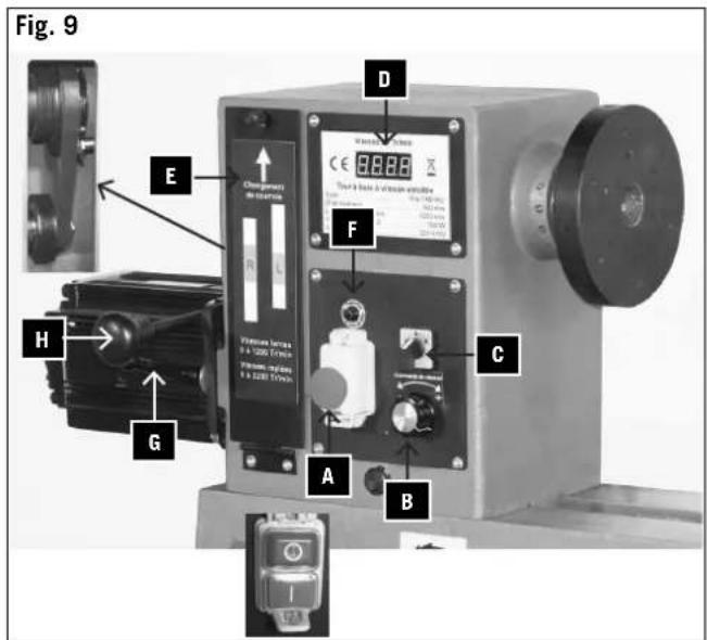
Adjustment of the speed Fig.9
The continuous setting of the rotations per minute (B) may only be done while the machine is running.
The speed is visible on the display (D) and may be adjusted in 2 levels.
1 Level from 0 - 1,200
2 Level from 0 - 3,200
The adjustment is performed by shifting the drive belt and is carried out as follows.
Attention! Unplug the mains plug.
1 Open the cover (E).
2 Open the belt clamping lever (G).
3 Lift the motor by means of the lever (H).
4 Set the belt to level 2.
5 Attention! The belt must be aligned accurately.
6 Clamp the belt and lock it with the clamp lever (G)
7 Rotate the spindle by hand slightly and check the belt run.
8 Close the cover and lock with the screw.
NOTE: Extremely high belt-tension causes rapid wear of the belt.
Close the casing and lock into place by turning the screw 1/4 of a revolution to the right. When the cover is closed, read the adjusted speed from the viewing-window. When working with highly unbalanced workpieces, select a speed at least one level lower.
Overload protection Fig.9 (F)
In the event of an overload, the machine switches the motor off.
Once the motor has cooled down, press the button (F). It is now possible to start work again.
Driver, Fig. 1.1, B
The driver is used exclusively for work between both centers.
Face plate, figure 1.1, A
The face plate is used with flat larger tools.
Changing the tensioning tools. Fig. 10
Unfasten the headless set screw on the shaft of the face-plate.
Rotate manually until the stopper bar snaps into place.
Remove the face-plate from the spindle by rotating it counter-clockwise.
Changing the carrier Fig. 11
The carrier is located in the cone of the spindle and is released by slightly knocking the stopper bar.
Attention!! When exchanging the tools, always clean the cone from dust and shavings.
Tailstock, figure 12
- Once the eccentric clamp has been loosened, the tailstock can be moved over the entire length of the bed and can be secured at any distance from the headstock.
- To insert a workpiece between the centers, loosen the binder, turn the sleeve approx. 20 mm outward and clamp.
- Slide the tailstock to the workpiece and place the tailstock center into the sunken point in the center of the workpiece.
- Screw out the tailstock sleeve until the tailstock center rests securely in the wood. Retighten the binder.
- Turn the workpiece to see if it rests securely between the two centers and can be rotated freely.
Tailstock center replacement, Fig. 12
- Loosen the binder (5).
- Turn tailstock spindle sleeve totally backwards until the tip can be removed.
Headstock, Fig. 13
The headstock is moveable and can be clamped into any position with the lever 1C.
By moving the headstock by 180^ , work pieces with a diameter of up to 500 mm can be worked with the extension console (accessory).
Tool holder, Fig. 14
- The tool holder both insures safe use of wood turning tools and at the same time serves as a support for the hand.
The height of the tool holder can be adjusted once the binder has been loosened. To turn further, pull in the direction indicated by the arrow.
- Place the tool holder at a distance of 1 – 3 mm from the workpiece. Check the adjustment in addition to rotating the workpiece by hand.
- Set the tool holder ca. 3 mm above the axis of the workpiece.
Check the adjustment once again by rotating the workpiece by hand.
- Once the eccentric clamp has been loosened, the holder console can be moved along the entire length of the bed and in the direction perpendicular to the workpiece. Furthermore, the holder console can be tilted over approx. 45^ to either side.
- To work with a plane surface, turn the tool holder 90^ and place up against the surface to be worked. Depending on the wood turning tool, place the tool holder up to 6 mm underneath the axis of the workpiece.
- If the headstock is swivelled, then the tool rest with the extension is to be used (Fig. 11).
- Therefore it is inserted from the left of the headstock so that larger discs can be processed.
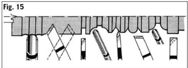
Use of wood turning tools, Fig. 15
Examples of how to use the tools when working with the most frequent forms. Once the machine has been plugged in, it is ready to be used. Observe the operating instructions in „Electrical connection“.
Operations
A perfect and sharp wood turner tool is a precondition for professional wood-turning.
Selection of materials
- Wood to be turned must be of good quality and without imperfections such as fissures against the grain, a marred surface, or knots. Faulty wood tends to split and becomes a risk for both the operator and the machine.
- Workpieces that have been glued together should only be processed by experienced craftsmen. Because the workpiece can explode as a result of developing centrifugal force, turning such wood demands careful gluing without weak points.
Note: Beginners should first master fundamental skills by working exclusively with solid material.
Preparation of the materials
- To turn long pieces of wood, the material must be cut into a square form beforehand.
- To turn a cross-arm, the material must be cut to size in its natural state as well. Saw out the rough form with a band saw. An octagonal form is recommended for the material so that vibrations are reduced.
Centering of the workpiece (Fig. 16)
Centering the prepared workpiece is an important operation to be performed before placing it into the machine. Centering consists of measuring the middle point of the workpiece and marking it with a center punch.
Make a depression of 1.5 to 2 mm in the middle point.
If the workpiece has not been centered exactly, strong vibrations will develop as a result of the imbalance. It is possible that the workpiece could be hurled outward as a result.
NOTE: Exact centering of the workpiece produces smooth concentricity.
While working with the turner
- Work with a rough workpiece should be conducted at low speeds.
- Only after the wood has been pre-turned (the pre-turning operation is complete once the basic form of the workpiece as well as an even concentricity have been achieved) can the speed be raised.
- The live center must be readjusted from time to time with the hand wheel. This operation only should be performed when the motor has been turned off.
The tailstock center should rest firmly in the wood. - Turn the workpiece by hand to check if it rests secured.
Marking of the workpiece, figure 17
Sometimes the workpiece has to be taken out before it has been completed. It is advantageous to mark the workpiece and the driver with a pencil first.
When placing the workpiece back in the machine, match the marks on the workpiece and the driver.
By means of the spindle locking bolt (E1), you can lock the spindle.
12 screenings with respectively 30^ are possible by marking out.
Specialized literature
Specialized shops offer appropriate specialized literature about wood turning. They can be a great help for beginners in their work as well as a source of ideas for experts.

Electrical connection
The installed electric motor is completely wired ready for operation.
The customer's connection to the power supply system, and any extension cables that may be used, must conform with local regulations.
Important remark:
The motor is automatically switched off in the event of an overload. The motor can be switched on again after a cooling down period that can vary.
Defective electrical connection cables
Electrical connection cables often suffer insulation damage.
Possible causes are:
- Pinch points when connection cables are run through window or door gaps.
- Kinks resulting from incorrect attachment or laying of the connection cable.
- Cuts resulting from running over the connecting cable.
- Insulation damage resulting from forcefully pulling out of the wall socket.
- Cracks through aging of insulation.
Such defective electrical connection cables must not be used as the insulation damage makes them extremely hazardous.
Check electrical connection cables regularly for damage. Make sure the cable is disconnected from the mains when checking.
Electrical connection cables must comply with the regulations applicable in your country.
Single-phase motor
- The mains voltage must coincide with the voltage specified on the motor's rating plate.
- Extension cables up to a length of 25 m must have a cross-section of 1.5 mm ^2 , and beyond 25 m at least 2.5 mm ^2 .
- The connection to the mains must be protected with a 16 A slow-acting fuse.
Only a qualified electrician is permitted to connect the machine and complete repairs on its electrical equipment. In the event of enquiries please specify the following data:
- Motor manufacturer
• Type of current of the motor - Data recorded on the machine's rating plate
- Data recorded on the switch's rating plate
If a motor has to be returned, it must always be dispatched with the complete driving unit and switch.
Maintenance
• Overhauls, maintenance work, cleaning, as well as the elimination of any malfunctions must only be undertaken after turning off the motor.
- All protective and safety equipment must be reinstalled immediately upon completion of any repair or maintenance work.
- Clean and lightly oil the spindle thread of the tool holder when changing tools.
- When possible, the tail stock sleeve should be removed by unscrewing it, cleaned and then sprayed with a dry lubricant. Grease the threaded spindle.
- Check the eccentric clamp of the tailstock as well as the tool holder and adjust if necessary. In addition, tighten the hex nut under the bracket.
- Check the drive belt and replace when necessary.
Accessories
Jaw chuck protection Fig. 18
When working with the jaw chuck (accessory), the jaw chuck protection must be used.
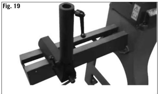
Extension console, Fig. 19
When working on a piece with a max. diameter of up to 500 mm, the extension console which is used must be attached on the frontal side. Thereby, the headstock is removed from the lathe bed, rotated by 180°, attached to the lathe bed and refastened. The standard tool support is employed here.
Article Art. No.
Screw chuck 7400 7200
Socket chuck ∅ 30 mm 7400 8600
Socket chuck ∅ 40 mm 7400 7300
Socket chuck ∅ 60 mm 7400 8700
Driver plate ∅ 80 mm 7400 8800
Three-jaw chuck ∅ 100 mm 7400 8900
Service information
Please note that the following parts of this product are subject to normal or natural wear and that the following parts are therefore also required for use as consumables.
Wear parts*: Carbon brushes, v-belt
* Not necessarily included in the scope of delivery!
Trouble shooting
| Problem Possible Cause Help | ||
| Motor doesn’t start | a) No electricityb) Defective switch, condenserc) Defective extension cord | a) Check fuseb) Have an electrician inspect unitc) Unplug cord, inspect and replace, if necessary |
| Drilled holes become larger than the drill bit | Headstock and tailstock are not parallel. Set up | headstock according to the tailstock tip. Insert carrier into the drilling spindle for this and position the tailstock with tip up to a distance of approx. 1°mm. |
| Work piece flatters while working | a) Working piece becomes loose while workingb) Work piece is not properly centeredc) Rotational speed is too high | a) Follow the instructions in the operating manualb) Follow the instructions in the operating manualc) Select a lower rotational speed |
| Tool rest or tailstock cannot be clamped | Setting the eccentric clamping Return the hexagonal nut at the bottom side about 12 rotation with the socket spanner | |
Manufacteur:
Scheppach
Contre-pointe, Fig. 12
Günzburger Straße 69
D-89335 Ichenhausen
Ärade kund,
Günzburger Straße 69
D-89335 Ichenhausen
Arvoisa asiakkaamme,
Günzburger Straße 69
D-89335 Ichenhausen
Vážený zákazníku,
Günzburger Straße 69
D-89335 Ichenhausen
Vážený zákazník,
Günzburger Straße 69
D-89335 Ichenhausen
Tisztelt ügyfelünk,
The object of the declaration described above fulfils the regulations of the directive 2011/65/EU of the European Parliament and Council from 8th June 2011, on the restriction of the use of certain hazardous substances in electrical and electronic equipment.
Apparent defects must be notified within 8 days from the receipt of the goods. Otherwise, the buyeris rights of claim due to such defects are invalidated. We guarantee for our machines in case of proper treatment for the time of the statutory warranty period from delivery in such a way that we replace any machine part free of charge which provably becomes unusable due to faulty material or defects of fabrication within such period of time. With respect to parts not
manufactured by us we only warrant insofar as we are entitled to warranty claims against the upstream suppliers. The costs for the installation of the new parts shall be borne by the buyer. The cancellation of sale or the reduction of purchase price as well as any other claims for damages shall be excluded.
Garantie FR

- Lata 7.0v
- DE
- FR
- Hersteller:
- Verehrter Kunde,
- Dear customer,
- Note
- We recommend
- General notes
- Noise parameters
- Acoustic power level in dB
- Controls and features (Fig. 1.1)
- General Safety Notes
- ⚠️ Proper use
- ⚠️ Remaining hazards
- Assembly (figure 2 - 8)
- Start-up
- Speed adjustment Fig. 7
- Guidelines for speed adjustment
- Adjustment of the speed Fig.9
- Attention! Unplug the mains plug.
- Overload protection Fig.9 (F)
- Driver, Fig. 1.1, B
- Face plate, figure 1.1, A
- Changing the tensioning tools. Fig. 10
- Changing the carrier Fig. 11
- Tailstock, figure 12
- Tailstock center replacement, Fig. 12
- Headstock, Fig. 13
- Tool holder, Fig. 14
- Use of wood turning tools, Fig. 15
- Operations
- A perfect and sharp wood turner tool is a precondition for professional wood-turning.
- Selection of materials
- Preparation of the materials
- Centering of the workpiece (Fig. 16)
- While working with the turner
- Marking of the workpiece, figure 17
- Specialized literature
- Electrical connection
- Important remark:
- Defective electrical connection cables
- Single-phase motor
- Maintenance
- Accessories
- Jaw chuck protection Fig. 18
- Extension console, Fig. 19
- Article Art. No.
- Service information
- Manufacteur:
- Scheppach
- Contre-pointe, Fig. 12
- Ärade kund,
- Arvoisa asiakkaamme,
- Vážený zákazníku,
- Vážený zákazník,
- Tisztelt ügyfelünk,
- Garantie FR
Brand : SCHEPPACH
Model : Lata 7.0v
Category : Wood lathe