
SBG 4910 - Saw Flex - Free user manual and instructions
Find the device manual for free SBG 4910 Flex in PDF.
| Brand | Flex |
| Model | SBG 4910 |
| Product type | Metal band saw |
| Dimensions (L x W x H) | 66 x 31 x 38 cm |
| Weight (with table) | 18 kg |
| Weight (without table) | 7.9 kg |
| Rated voltage | 230 V |
| Frequency | 50 Hz |
| Power input | 850 W |
| Power output | 445 W |
| Cutting speed | 60 / 80 m/min (2 levels) |
| Band length | 1335 mm |
| Band width | 13 mm |
| Band thickness | 0.65 mm |
| Teeth | 8/12 teeth per inch |
| Cutting angle | 0° to 45° (continuously adjustable) |
| Cutting capacity (at 0°) | Round up to 80 mm, square up to 80x100 mm |
| Sound pressure level | 82 dB(A) |
| Sound power level | 93 dB(A) |
| Vibrations (cutting steel tube) | 2.3 m/s² (uncertainty K=1.5 m/s²) |
| Protection class | II / □ |
| Compatible materials | All metals except hardened steel |
| Included accessories | Parallel stop, wrenches |
| Maintenance | Regular cleaning, disconnect before maintenance |
| Safety | Protective equipment mandatory, emergency stop |
| Spare parts | Available at www.flex-tools.com |
Frequently Asked Questions - SBG 4910 Flex
User questions about SBG 4910 Flex
0 question about this device. Answer the ones you know or ask your own.
Ask a new question about this device
Download the instructions for your Saw in PDF format for free! Find your manual SBG 4910 - Flex and take your electronic device back in hand. On this page are published all the documents necessary for the use of your device. SBG 4910 by Flex.
USER MANUAL SBG 4910 Flex
Manager Research & Development (R & D)
Klaus Peter Weinper Eckhard Ruhle
Head of Quality
Department (QD)
30.06.2015
Symbols used in this manual 14
Symbols on the power tool 14
For your safety 14
Noise and Vibration 16
Technical specifications 16
Overview 17
Instructions for use 18
Operating instructions 23
Maintenance and care 23
Disposal information 23
-Declaration of Conformity 24
Exemption from liability 24
Symbols used in this manual

WARNING!
Denotes impending danger.
Non-observation of this warning may result in death or extremely severe injuries.

CAUTION!
Denotes a possibly dangerous situation.
Non-observation of this warning may result insight injury or damage to property.

NOTE!
Denotes application tips and important information.
Symbols on the power tool

Before switching on the power tool, read the operating manual!
Disposal information for the oldmachine (see page 23)!
For your safety

WARNING!
Before using the metal band saw, please read and follow:
-these operating instructions,
-the "Information on handling power tools" in the enclosed booklet (leaflet no. 315.915),
-the currently valid site rules and theregulations for the prevention of accidents.
This metal band saw is state of the art and has been constructed in accordance withtheacknowledged safety regulations.
Nevertheless, when in use, the power tool may be a danger to life and limb of the user ora third party, or the power tool or other property may be damaged. The metal band saw may be operated only if it is
-used as intended,
-in perfect working order.
Faults which impair safety must be repaired immediately.
Intended use
This metal band saw is designed
-
for commercial use in industry and trade,
-
for dry, straight cutting of all metals, except stainless hardened steel, with the material clamped in position,
not designed for cutting wood, bones or similar materials,
- for use with saw bands and accessories which are indicated in this manual or recommended by the manufacturer.
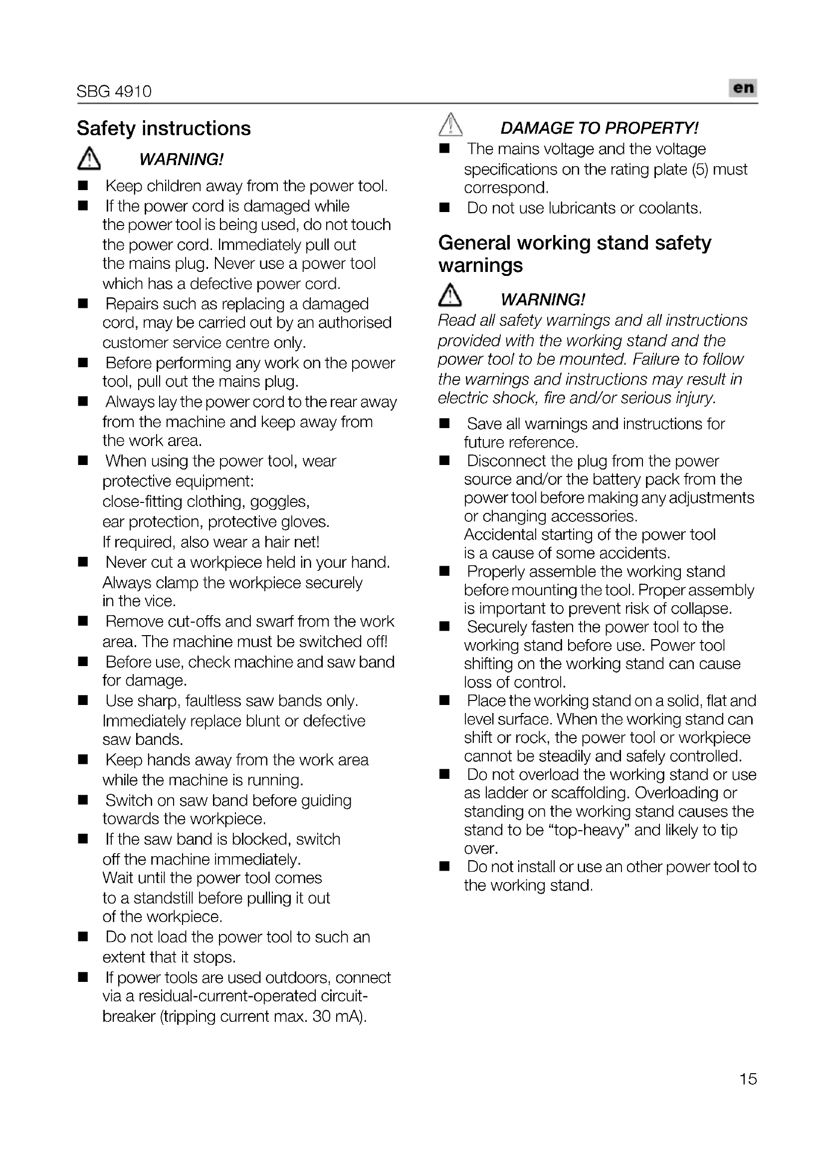
Safety instructions

WARNING!
Keep children away from the power tool.
If the power cord is damaged while the power tool is being used, do not touch the power cord. Immediately pull out the mains plug. Never use a power tool which has a defective power cord.
Repairs such as replacing a damaged cord, may be carried out by an authorised customer service centre only.
Before performing any work on the power tool, pull out the mains plug.
Always lay the power cord to the rear away from the machine and keep away from the work area.
When using the power tool, wear protective equipment: close-fitting clothing, goggles, ear protection, protective gloves. If required, also wear a hair net!
- Never cut a workpiece held in your hand. Always clamp the workpiece securely in the vice.
Remove cut-offs and swarf from the work area. The machine must be switched off!
Before use, check machine and saw band for damage.
Use sharp, faultless saw bands only. Immediately replace blunt or defective saw bands.
- Keep hands away from the work area while the machine is running.
- Switch on saw band before guiding towards the workpiece.
If the saw band is blocked, switch off the machine immediately. Wait until the power tool comes to a standstill before pulling it out of the workpiece.
- Do not load the power tool to such an extent that it stops.
If power tools are used outdoors, connect via a residual-current-operated circuit-breaker (stripping current max. 30mA ).

DAMAGE TO PROPERTY!
The mains voltage and the voltage specifications on the rating plate (5) must correspond.
- Do not use lubricants or coolants.
General working stand safety warnings

WARNING!
Read all safety warnings and all instructions provided with the working stand and the power tool to be mounted. Failure to follow the warnings and instructions may result in electric shock, fire and/or serious injury.
Save all warnings and instructions for future reference.
- Disconnect the plug from the power source and/or the battery pack from the power tool before making any adjustments or changing accessories.
Accidental starting of the power tool is a cause of some accidents.
- Properly assemble the working stand before mounting the tool. Proper assembly is important to prevent risk of collapse.
- Securely fasten the power tool to the working stand before use. Power tool shifting on the working stand can cause loss of control.
- Place the working stand on a solid, flat and level surface. When the working stand can shift or rock, the power tool or workpiece cannot be steadily and safely controlled.
- Do not overload the working stand or use as ladder or scaffolding. Overloading or standing on the working stand causes the stand to be "top-heavy" and likely to tip over.
- Do not install or use an other power tool to the working stand.
Noise and Vibration
The noise and vibration values have been determined in accordance with EN 60745.
The A evaluated noise level of the power tool is typically (at no load):
- Sound pressure level: 82
Sound power level: 93 dB(A);
Uncertainty:
Total vibration value when sawing steel tube:
Emission value: a h = 2.3m / s^2
Uncertainty: ^2 K

CAUTION!
The indicated measurements refer to new power tools. Daily use causes the noise and vibration values to change.

NOTE!
The vibration emission level given in this information sheet has been measured in accordance with a standardised test given in EN 60745 and may be used to compare one tool with another. It may be used for a preliminary assessment of exposure.
The declared vibration emission level represents the main applications of the tool. However if the tool is used for different applications, with different accessories or poorly maintained, the vibration emission may differ. This may significantly increase the exposure level over the total working period.
An estimation of the level of exposure to vibration should also take into account the times when the tool is switched off or when it is running but not actually doing the job. This may significantly reduce the exposure level over the total working period.
Identify additional safety measures to protect the operator from the effects of vibration such as: maintain the tool and the accessories, keep the hands warm, organisation of work patterns.

CAUTION!
Wear ear protection at a sound pressure above 85 dB(A).
Technical specifications
dB(A)
| Metal band saw SBG 4910 | |
| K Saw band Bi-metallic= | 3 |
| Band length mm | 1335 |
| Band width mm | 13 |
| Band thickness m/m= | 0.65 |
| Toothing Teeth/ inch | 8/12 |
| Cutting rate m/min 60/80 | |
| Cutting area Table | Page 23 |
| Nominal voltage V/Hz 230/50 | |
| Power input W | 850 |
| Power output W | 445 |
| Dimensions (L x W x H) cm | 66x31x38 |
| Weight Saw with machine table kg Saw without machine table (free-hand sawing) kg | 18 |
| 7.9 | |
| Protection class | II / ☑ |
Overview
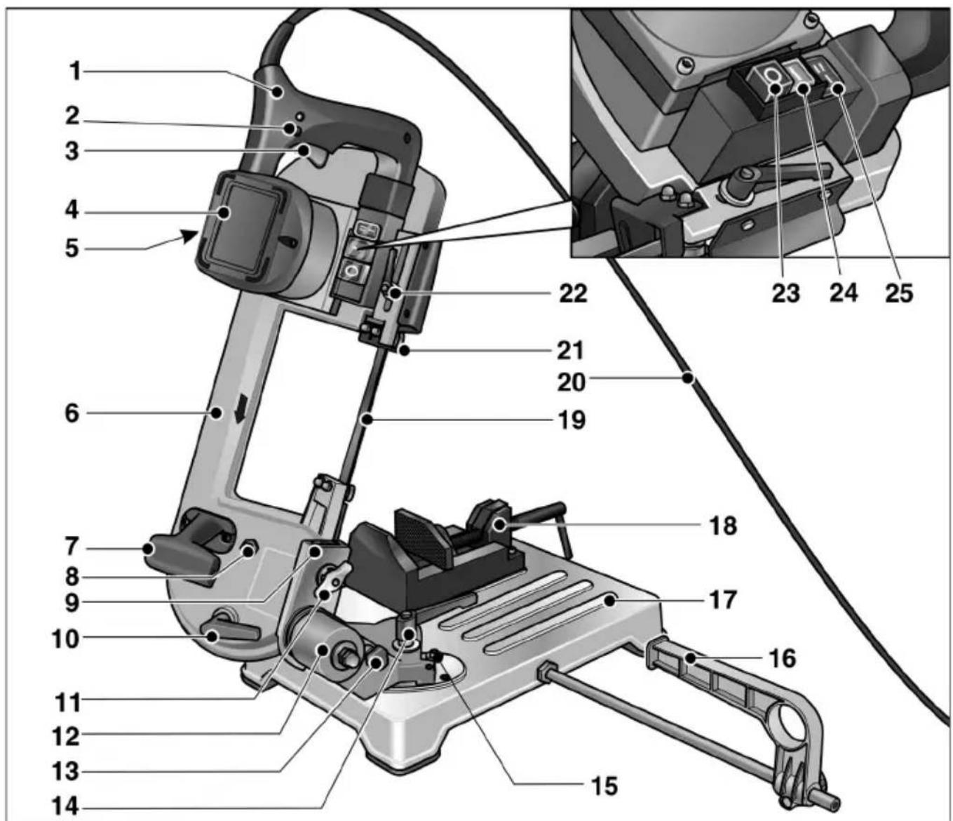
1 H a n d I e
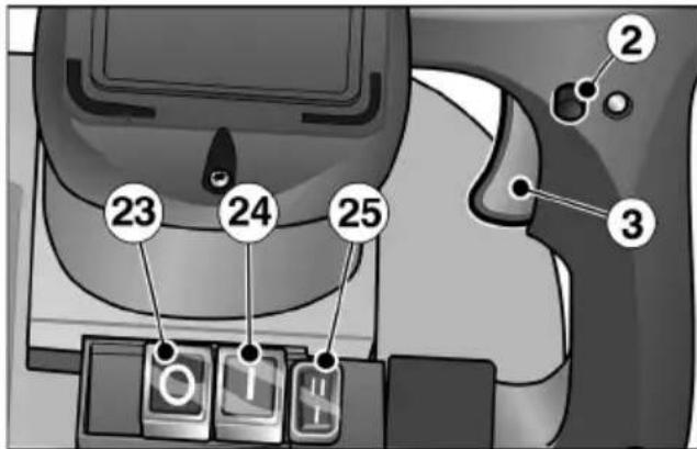
2 Locking button
3 S W i t c h
4 Motor
5 Rating plate
6 S a w f r a m
7 Carrying handle
8 Screw for adjusting the saw band
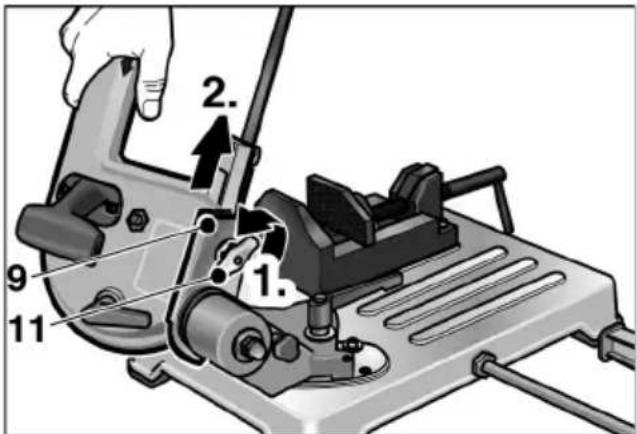
9 Dovetail guide
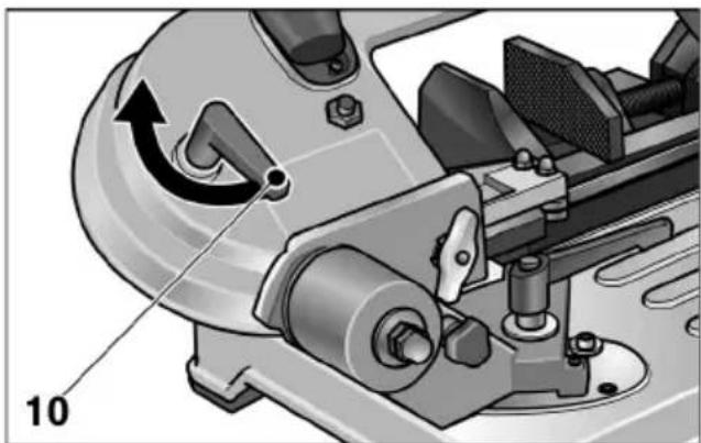
10 Tension lever (saw band tension)
11 Wing nut
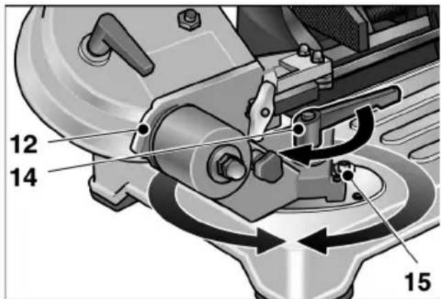
12 Swivel support
13 Locking pin for saw frame
14 Clamping lever (swivel support)
15 End stops for swivel support
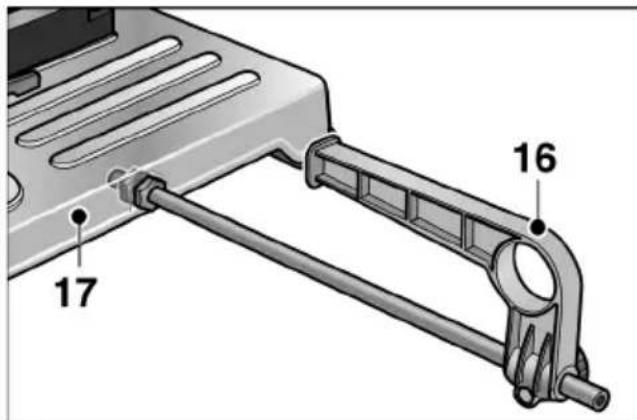
16 Parallel stop
17 Machine table
18 Machine vice
19 Saw band
20 Power cord
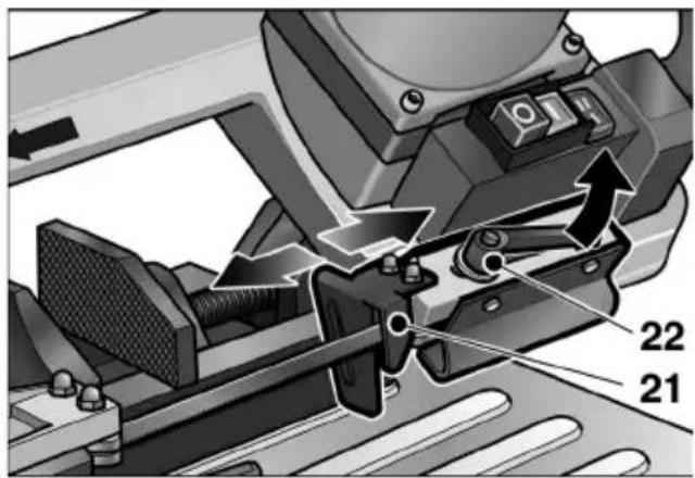
21 Saw band guide, adjustable
22 Clamping lever (saw band guide)
23 Main switch "Off/0"
24 Main switch "On/I"
25 Selector switch for cutting speed
Instructions for use

WARNING!
Before adjusting the power tool, always press the main switch Off/0 (23).
Before switching on the power tool
Unpack the metal band saw and check that no parts are missing or damaged.
Compare the mains voltage with the specifications on the rating plate (5).
Assembling the metal band saw:
Place dovetail guide (9) in the uppermost position.
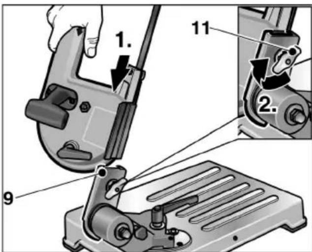
Insert saw into the dovetail guide.
Tighten wing nut (11) to secure the saw.
Fold saw down.
Transport and installation
- Lift the machine onto the machine table (17).
or
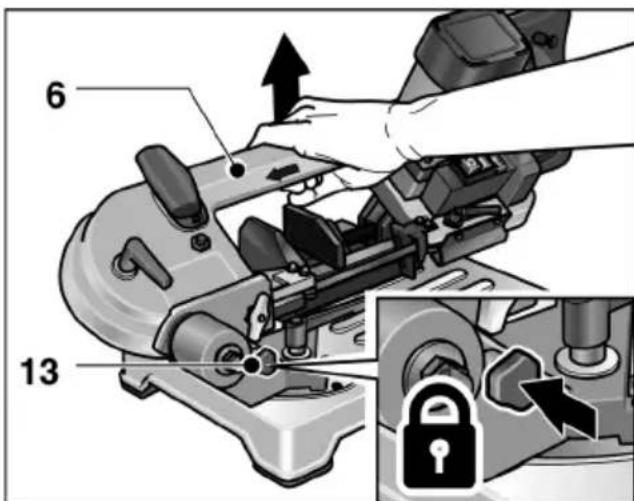
Insert locking pin (13) into the opening on the swivel support (12) and raise the power tool on the saw frame (6).

CAUTION!
When selecting the installation location, ensure that the installation surface is adequately stable and that there is sufficient light.

NOTE!
The ergonomically optimum working height is 90-95 cm.
Switch on and off
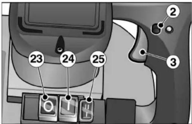
Press main switch On/1 (24).
Brief operation without engaged switch rocker:
Press and hold down the switch (3).
To switch off, release the switch (3).
Continuous operation with engaged switch rocker:
Press and hold down the switch (3).
To lock into position, hold down the locking button (2) and release the switch.
To switch off, briefly press and release the switch (3).
Switching off:
Press main switch Off/0 (23).

NOTE!
Following a power failure, the switched onpower tool does not restart.
Adjusting the cutting rate
Set the required cutting rate with the switch (25).
-1 = 60 m/min
- II = 80 m/min
Tensioning the saw band
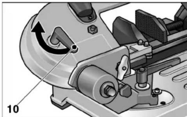
Swivel tension lever (10):
Anti-clockwise:
Tension saw band
- Clockwise:
Release saw band tension

CAUTION!
If the tension is too high, the saw band hasatendency to run out of the guides.
Adjusting the saw band guide

WARNING!
Before adjusting the power tool, always press the main switch Off/0 (23).

CAUTION!
Adjust the saw band guide according to the dimensions of the workpiece whichisto be cut. This provides:
-an increased protective effect,
-the saw band with protection from overloading,
-an improved cutting quality.
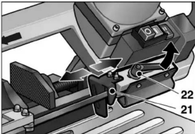
Loosen the clamping lever (22) and feed the saw band guide (21) as far as possible along the workpiece.
Tighten the clamping lever (22).
Changing the cutting angle

WARNING!
Before adjusting the power tool, always press the main switch Off/0 (23).
The cutting angle can be adjusted stepplessly from 0^ to 45^ (end stop).
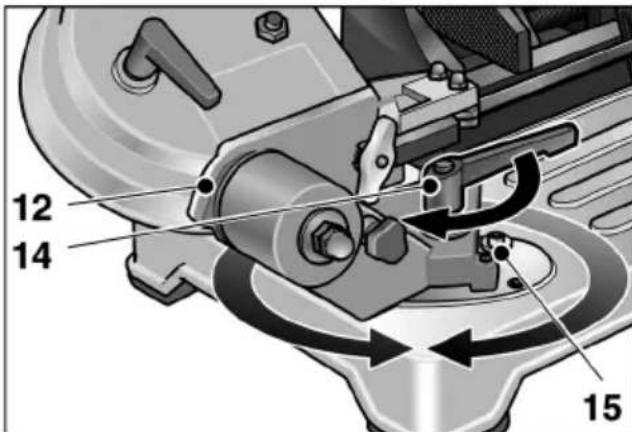
Loosen the clamping lever (14) and set the swivel support (12) to the required cutting angle.
Use the scaling on the machine table as an adjustment aid.
Retighten the clamping lever.
Changing the saw band

WARNING!
Before adjusting the power tool, always pressthe main switch Off/0 (23) and pulloutthe mains plug.

CAUTION!
Risk of injury! Wear protective gloves.
Press the main switch Off/0 (23) and pull out the mains plug.
Loosen the clamping lever (22) and push back the saw band guide (21) as far as the stop.
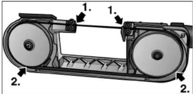
After loosening the 4 screws, remove the protective housing from the saw frame.
Release saw belt tension by swivelling the tension lever (10) clockwise.
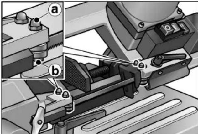
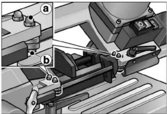
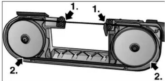
Slacken the hexagon-head nuts a (A/F 10) on both outer saw band guides.
Rotate screw b (A/F 10) slightly in an anticlockwise direction until the saw band is released.
First take the saw band off the guide rollers and then out of the guides.
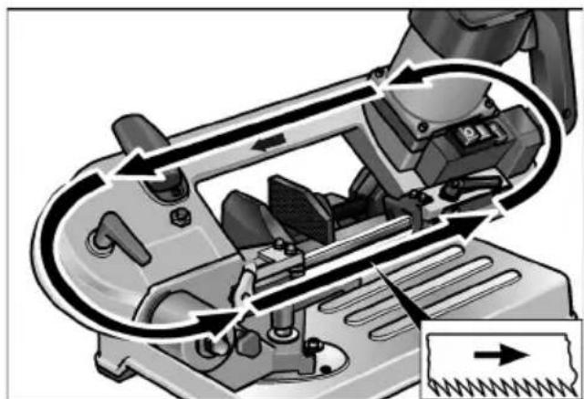
Insert the new saw band:
First into the guides, then onto the guide rollers.
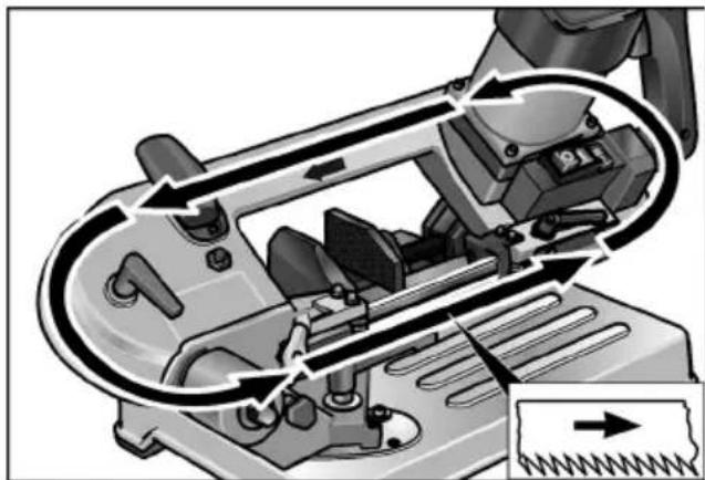
Observe the direction of cut!
Tension saw band (see page 19).
Align the saw band guide by rotating the screw (A/F 10) slightly in a b clockwise direction until the guide just touches the saw band.

NOTE!
The saw band guides must be adjusted until they lightly touch the saw band and rotate asthe saw band passes through them! They must not be blocked!
- Tighten the hexagon-head nuts a (A/F 10).
- Attach the protective housing.
Move the saw band guide (21) into the operating position and tighten the clamping lever (22).
Running in the saw band

NOTE!
To ensure an optimum cutting result, each new saw band must be run in.
To do this:
Clamp 40-50 mm round steel in the vice.
Make three cuts into solid material See section "Sawing with machine table". Start by applying very little pressure on the handle for the first cut, increase the pressure slightly for the subsequent cuts. For the last cut the cutting time should not be less than 4 minutes!
A correctly run-in saw band produces a higher cutting quality and has a longer service life.
Sawing

CAUTION!
Before use, always check the machine and saw band for damage.

NOTE!
Excessive feed will reduce the capacity of themachine, impair the cutting quality and reduce the service life of the saw band.
Sawing with machine table
Clamp the workpiece firmly in the vice (18).
Adjust the saw band guide (21) according to the workpiece dimensions.
Switch on the device.

CAUTION!
Risk of injury! Always keep your left hand on the outside of the cutting area.
Take hold of the handle (1) with your right hand and press the switch. Slowly feed the saw frame (6) along the material.
After making the first cut, increase the pressure. Apply uniform feed through the material.
After cutting the material, release the switch and move the handle to its original position.
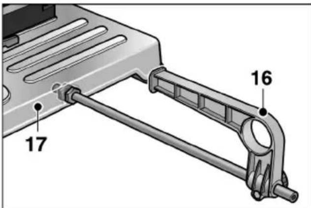
If required, attach parallel stop (16). When not in use, fix in the holder under the machine table (17).
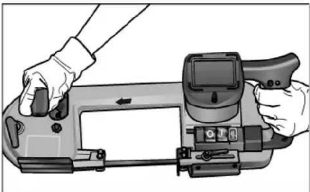
Free-hand sawing
The saw can be removed from the machinetable (17). This allows free-hand sawing as required (e.g. permanently installed workpieces).

CAUTION!
- Before use, always check the machine and saw band for damage.
- When sawing, always place the saw band guide (21) on the workpiece.
-Switch on saw band before guiding towards the workpiece. Never switch on the power tool with thesaw band on the workpiece!
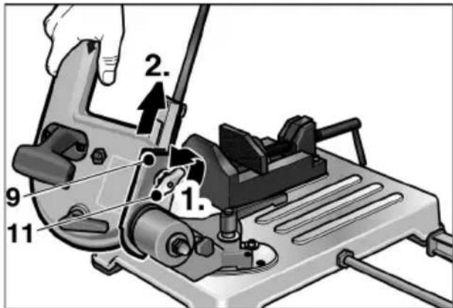
Loosen wing nut (11) and pull saw out of the dovetail guide (9).
Switch on the device.

When sawing, always hold the saw with both hands.
Place saw band guide (21) on the material.
Press the switch. Slowly feed the saw band (19) along the material.
After making the first cut, increase the pressure. Apply uniform feed through the material.
After cutting, release the switch.
After working, re-attach the saw to the machine table.
Operating instructions
Cutting rate
Cutting into solid material: Setting I (60 m/min)
Cutting into hollow material: Setting II (80 m/min)
Cutting area
| Workpiece profile | Cutting angle | Cutting area [mm] |
| ○ | 0°<80 | <80 |
| □ | ||
| □ | <80 x 100 | |
| ○ | 45°<60 | <68 |
| □ | ||
| □ | <55 x 68 | |
| ○ | Free-hand sawing | <80 |
| □ | <80 | |
| □ | <80 x 150 |
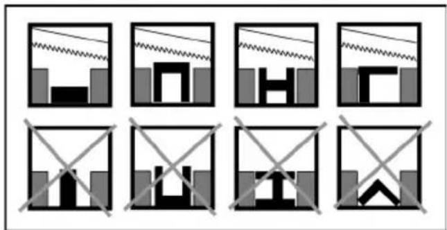
Clamping the material correctly in the vice
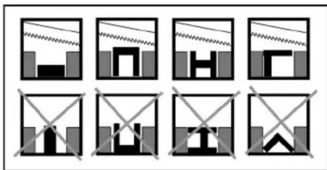

NOTE!
If profiles are made of a very thin material, insert another piece into the profile which matches the shape of the profile, thereby reducing the risk of distortion.
Maintenance and care

WARNING!
Before performing any work on the power tool, pull out the mains plug.
Cleaning

CAUTION!
RISK OF INJURY! Never use compressed air to blow swarm away.
Regularly clean the power tool.
Regularly remove cut-offs and swarm from the cutting area.
Prolonged non-use
Clean the power tool.
Relieve the tension on the saw band.
Store the machine in a dry, well ventilated room.
Repairs

NOTE!
Use only original parts supplied by the manufacturer for replacement purposes. If non-original parts are used, the guarantee obligations of the manufacturer will be deemed null and void.
Repairs such as replacing a damaged cord, may be carried out by an authorised customer service centre only.
Spare parts and accessories
Other accessories, in particular insertion tools, can be found in the manufacturer's catalogues.
Exploded drawings and spare-part lists can be found on our homepage:
www.flex-tools.com
Disposal information

WARNING!
Render redundant power tools unusable byremoving the power cord.
Redundant power tools are not worthless rubbish. They contain metals and plastics which can be recycled.
The packaging is used to protect the power tool while it is being shipped to the customer. All utilised packaging materials are environmentally friendly and recyclable.

NOTE!
-Pleases ask your dealer about disposal options for redundant power tools.
-Pleases ask your dealer or inquire at your municipal authority about disposal options for the packaging materials.
-Declaration of Conformity
We declare under our sole responsibility that the product described under "Technical specifications" conforms to the following standards or normative documents:
EN 60745 in accordance with the regu
lations of the directives
2004/108/EC (until 19.04.2016),
2014/30/EU (from 20.04.2016),
2006/42/EC, 2011/65/EC.
Responsible for technical documents:
Exemption from liability
The manufacturer and his representative are not liable for any damage and lost profit due to interruption in business caused by the product or by an unusable product.
The manufacturer and his representative are not liable for any damage which was caused by improper use of the power tool or by use of the power tool with products from other manufacturers.
Table des matieres
Symbolesutilisés 25
Manager Research & Head of Quality Development (R & D) Department (QD)
Manager Research & Development (R & D)
Klaus Peter Weinper Eckhard F
Head of Quality
Department (QD)
Manager Research & Development (R & D)
Klaus Peter Weinper Eckhard F
Head of Quality
Department (QD)
Klaus Peter Weinper Eckhard Ruhle
Head of Quality
Department (QD)
Manager Research & Development (R & D) 30.06.2015
Head of Quality Department (QD)
Manager Research & Development (R & D)
Klaus Peter Weinper Eckhard Ruhle
Head of Quality
Department (QD)
30.06.2015
Manager Research & Development (R & D)
Head of Quality Department (QD)
Manager Research & Development (R & D)
Klaus Peter Weinper Eckhard Ruhle
Head of Quality
Department (QD)
Manager Research & Head of Quality
Development (R & D) Department (QD)
Manager Research & Development (R & D)
Klaus Peter Weinper Eckhard Ruhle
Head of Quality
Department (QD)
Manager Research & Development (R & D)
Klaus Peter WeinperEckhard F
30.06.2015
Head of Quality
Department (QD)
I npnoHnMnte 3JIeKtpOnHCTpyMeHT Ha cToJe cTaHka (17)
UJN

BCTaBbTe yCTaHOBOHbI uTnΦT (13) B OTBepCTne IOBOPOTHO KPOHHTeHa (12) n npINOdHMITE aJeKtpoHHcTpymEHT 3a cKOby nJIbI (6).

BHIMAHHE!
Pn BbIope MeCTa yCTaHOBKn yJeJIHTe DOJIKHoe BHIMaHHe DoCTaTOOH CTAbNbHOCTn NOBepXHOCTn Ha MeCTe YCTaHOBKn n HAIuHIO DOCTaTOOHORO OCBeueHn.

YKA3AHVE!
ONTUMaJIbHaB B 3pROHOMUYeCKOM OTHOWeHH pa6oHaB bICota -90-95 cm.
BkJIIOUeHne N BbIKJIIOUeHne
HaKMnTe Ha rIaBHbIM BblKJIIOyAteJIb «BkJ./I» (24).
KpaTKOBpeMeHHbI peXIM pa6oTbI 6e3Фнкcaци:
HaXMMTe Ha BbIKIOuChaTeIb (3) n ydepxkBaIte ero B HaxaTOM NOIOXKeHN.
YTo6bI BbIKJIOHHTb 3JIeKTPoINHCTpyMeHT,OTnycTtTe BbIKJIOUaTeJIb (3).
IocToHHbI pexm pa6oTbI c qNKcaUnei:
HaXMMTe Ha BbIKIIOuChaTeJIb (3) N ydePKNBaIte eIRO B HaxKaTOM NOJIOKeHIN.
YTo6bl 3aΦnKcnpoBaTb, OTnyCTnte BbIKJIIOHATeJIb, yIepXnBaB B HaxkatoM NOJIOKeHN KHOKNy QnKcauN (2).
YTO6bI BbIKJIOHTb 3JIeKTPoHCTpyMeH,HaKMITE KOpOTKO Ha BbIKJIOUaTeJIb (3) n OTNyCTnTe.
BbIKJIIOueHHe:
HaXMMTE Ha rIaBbIi BblKIOuAteJIb «BbIKJ./0» (23).

YKA3AHVE!
Iocne nepepbBa B noJaue 3JeKtpo-3HepnBkJIOueHHbI 3JeKtpoINHcTpymEt He BO3O6HOBJaTe paBoTy.
Pereynipobka ckopocn pe3kn
YCTaHOBnTe Heo6xOdMyIO CKOpocTb pe3Kn C NOMoUsbIO NepeKJIouaTeJIA (25).
$$ \begin{array}{l} - 1 = 6 0 \mathrm {M} / \mathrm {M N H} \ - \mathrm {I I} = 8 0 \mathrm {M} / \mathrm {M N H} \ \end{array} $$
HaTaeKeHne JeHToUHOro NOJIOTHa
■ NobeprHnte 3axmHOn pbIar (10):
- npOTnB YacOBcTpeJKN:
IOBbICHTb HATXKeHne JeHToCHOro IIOJOTHa
- no ha c o Boi CtpeJIke:
OcnaBt b HataXeHne JeHToHoro nIoTHa

BHIMAHHE!
B cnyuae cniuKOM cnIbHOro haTAXeHnAJIeHTOuHOE NOJIOTHOBbIXoNT N3HaPpaBIAIOxN.
PereynilpOBka HnpaBIAIOseJLeHToCHOro NOLOTHa

NPEyNPEXKDEHVE!
Ipei npoBeHnem Bcex pa60T no HanaKe 3JIeKTPoHnHCTpyMeHTa Oba3aTeJIbHO BbIKJIOHTe erO C NOMOoiBIO rIaBHOrO BbIKJIOHTaTeJIA «BbIKJ./0» (23).

BHIMAHHE!
YCTAHOBNTE HAnpaBJIHIOJU JIeHTOCHORO
NOJOTHa B COOTBETCTBUN C pa3MepaMn
pacNJIbAEMORO N3JeJINr.
BlaorOapra 3TOMy:
-
NOBbIaETCA 3auNTHOe DeIcTBnE,
-
ObecneuBaeTc3aunTaJeHToHOro NOJOTHa OT N36bIToHOn Harpy3Kn,
- ynyuhaetcKaueCTBO pe3KN.
Ocna5bTe 3axmHOn pbIaR (22), n KaK MoXHo 6nXe npuBnHbTe HappaBnHOuyo JeHTOCHOro NOLOTHa (21) K O6pa6aTbIBaEMOMy IVdEJIIO.
3aTAHnTe 3axmHOn pbIar (22).
I3meHeHne yrJa pe3Kn

NPEyynPExKdEHVE!
Ipeed Haayanom BcexpapoT no HanaKe 3JIeKTPoHnHCTpyMeHTa HaxMITE Ha IaBbIi BbIKIOHaTeJIb «BbIK./0» (23). YroJ pe3Kn nepeKIOaETc 6ecctyHnHuTo oT 0^ do 45^ (KOHeuHbI pyHKT).
Ocna6bTe 3axmHoi pbHa (14) n yCTaHOBnTe NOBOPoTHbI KPOH- uTeiH (12) Ha Tpe6yembl yroJ pe3Kn.
B KaueCTBe BCNOMoTaTeJbHOrO cpeIcTBA IcNoJIb3yIe TpaIyIpOBky Ha CToJIe CTAHka.
3aTAHHTe CHOBA 3aXHMHOI pbUaI.
3aMeHa JeHToCHOro nOJIoTHa

NPEyPPEKDEHNE!
Ipeud Haayalom Bcex pa6oT no HaJaKe 3JIeKTPoHnCTpyMeHTa HaxMNTe Ha IaBHyI BbIKJIOHaTeJIb «BbIKJ./0» (23) I N3BJIeKITe BNJKy N3 pO3ETKn.

BHIMAHHE!
Onachoctb noyuHnra TpaBM!HaedeBaHTe 3aunTHbIe nepaTkn.
HaKMnTe Ha rIaBbI BbIKIOaTeJb «BbIK./0» (23) n n3BJeKnTe BNJKy n3 pO3eTKn.
Ocna6bTe 3axmHOn pbUar (22) n OTOdBnHbTe Ha3aI Do ynpa HAnpaBJIIOyIO JeHTOCHOro noIoTHa (21).
CHIMITE 3aunTHbIKoKyx COCKobI NJIbI,ocna6nB4BnHTa.
Ocna6bTe HaTJKeHne JHeHTOCHORo NOJOTHa NOBOPOTOM 3aXmHOrOp bHaRa (10) no YacOBoi CTpeJIke.
Ocna6bTe wectnrgpaHHbIe raIKn a (WnpHa 3eBa 10) o6oNX HApyXhIx HAnpabJIOxN JHeHToCHOro NOLOTHa.
I NobepHnte CJIerka npOTnB YacOBOn CTpeJIKN BnHT b (WnpHa 3eBa 10) TaK, TTO6bl O6HaXnTB JeHToOHoe NOLOTHO.
CHIMITEJeHToHoeNoIOTHO ChaJaC OTBOHbIXPOJIKOB,a3aTEMn3 HaPpaBJIIOx.
BctabBe HOBoE JeHToHoe NOJIOTHO:
Cnayala B HappaBJIIOUne, a 3aTeM Ha OTBOHbIe POJIKN.
O6paTITe BHMaHne Ha HApBaJIeHne pe3Kn!
HaTAHInTeJeHToUHOeNoJIoTHO (CM.CTp.215).
YcTaHOBnTe POBHO HApPaBJIHOuYO JeHToCHOro NIOJTHa, JIA 3TOrO NOBepHnTe BnHT b (WnpHa 3eBa 10) CJERKa No YacOBoN CTpeJIKe TaK, UTO6bl HaPpaBJIHOaI pRMo KacaJaAcb JeHToCHOro NIOJTHa.

YKA3AHVE!
HaipabJIOUneJeHToCHoroNoJOTHa 0JIJKbI 6bITb yCTaHOBJeHbTaKIM 06pa3OM,TO6bl OHn CJIeRka KacaJIncb JeHTOCHOro NOJOTHa N IOBopaYHBaJIncb npEr oXoe. OHN He JOnJxHbI 6bITb 3a6JOKpOBaHHbIMN!
3aBHTnte 8eCTnrgpaHHbIe raIKn a (WnpHa 3eBa 10).
3aФИКСИРУТe 3aIHTHbI KoxyX.
YcTaHOBnTe HaPpaBJIIOUyIO JeHToCHOrO NoIOTHa (21) B pa6ooyem NIOJKeHN I 3aTAHnTe 3aXkMHOI pbIar (22).
06kaTka JeHToCHOro noJIoTHa
i
YKA3AHVE!
JIH ONTUMaJIbHbIX pe3yJbTaTOB pe3KN KaKdoE HOBOE JeHToUHoe NIOJTOHO CNeIyET NOBepRaT npOeIype O6KaTKn.
ДЛЯЭТΟ:
3aKaTb B TnCKax KpyrIyIO CTaJIb 40-50 MM.
BbINOHNITb TpN npOnnla CnIOoHOro MaTePnAna CM. pa3deJ «Pe3ka co cToIOM cTaHka». HaChnTe nepBbI INpONIL C OueHb JERKIM HaXKaTHeM Ha pyKOaTKy, BO BpeM BAIOJIeHnA CJeDyUOuX INpONIOB HEMHO YcINIBaIte KaKdbI pa3 HaXKaTne. IocJIeHN INpONIN DOJIKeH dIInTBcH He MeHee 4 MNHyT!
IpaBnJIbHO BbINOJIHeHHa 06KaTka NObblaet KaYeCTBO pe3Kn yBeJIuHBAe CpOK cJyX6bl JeHTOCHOro noIoTHa.
Pe3ka
#
BHIMAHHE!
IpeJ KaKdbIM NcNoJb3OBAHnEM npOBepaIte 3JIeKTPoINHCTpyMeHT nJeHTOuHOe NOJTOHO Ha IpeJMet OTCyTCTBnI NOBpeJDeHnI.
i
YKA3AHVE!
CnIshKOM 6bICTpoe npoDbHXeHne CHXKaET MOuHOCtB 3JIeKTPOHnHCTpyMeHTa, yxuHaet KaueCTBO pe3KN u COKpaauaET cPOK cnJx6blJeHTOHO NOIoTHa.
Pe3ka co cTOJOM cTaHka
3aФИКСИРУТe HaIeXH O6pa-6aTbIbAeMOe I3dJIe B 3aXIMHbIX TnCKax (18).
YCTAHOBNTe HAnpaBnIyU JeHTOCHoroNoJToHa(21)BCOTBETCTBNC pa3MepamNobpa6aTbIbAemOr0N3DeJIINr.
BkIIOUHTe 3JIeKTPoHCTpyMeHT.
#
BHIMAHHE!
Onachoctb nolyeHn TpaBM!JeByIO pyKy
depxte Bcerda BHe 30HbI npOnila.
YdepknBa pyKoTky (1) npaBoi pyKo, HaxMITE Ha BbIKIOuHaTeJb. Cko6y nIbI (6) MeJeHHO np6JIIN3bTe K MaTePnAny.
I NocJIe IorpyKeHnI NIIbI B MaTePnaJI yCINbTe HaXaTne. IpoDBrIaNTEcB pa3MepeHHO CKBO3b MaTePnaJI.
I Nocne OKOHuaHnpe3Kn OTnyCTnTe BbIKJIOHaTeJIb n yCTaHOBnTe pyKoTky B INCXOJHOM IIOJOKeHN.
Pn Heo6xOIMOCtyn yCTaHOBNTe napaJIeJIbHbIynp (16).Bcnyae HEnCNoJIb3OBAHN3aФNKcpynte B KpeJIeHNIOCTOJOM CTaHka (17).
PyuHa pe3Ka
Пиla ChИMaeTcR co cToJa cTaHka (17). 3TO nO3BOLnR T np HEO6XoDnMoCTn (HaNP., HaIyxo BCTpoEHHbI e O6pa6aTbI- BaembIe N3dJIIN) BblIOJHrTb pyHyIO pe3Ky.
#
BHIMAHHE!
- IpeK KaKdbIM NcNoJb3ObaHnEM npOBepaIte 3JIeKTPoINHCTpyMeHT UJeHTOuHO pIoTHO Ha IpeJMetOTCYTCTBnI NOBpeKdEHN.
- HanpaBnIouaJJeHToUHO nOIoTHa (21) npi pe3Ke IOnJxHa Bcerda npuIeratb Obpa6aTbIbAemomy 3dJIIO.
JIeHTOuHoe NOJIoTHo Oba3aTeIbHO IOJxHo 6bITb BKIOUyeHHbIM npn erO NOrpyXeHN B O6pa6aTbIBaEMOE n3JeIe. Hn B KOem Cnyue He BKIOUaTb 3JIeKTPoHcTpyMeHT C pNIXaTbIM K MaTePnaJy JIeHTOuHbIM INoJToHOM!
Ocna6bTe KpbIbUaTyu raKy (11) nN3BnEKeTpe NnIy N3 HappaBIAIOuei TnPa JAcTOckHa XBOCTa (9).
BkJIOHTe 3JIeKTpOHnHCTpyMeHT.
BoBpe3knPiNy cIeIyEt IepXkaTb Bcerda oBeIMn pyKaMn.
HapablaioyIO JeHTOCHOro NIoTHa (21) nloTHO npnxMnte K MaTePnaJy.
HaXMMTe Ha BbIKJIIOuHaTeIb. JeHToUHoe NIoTHO (19) MeJJeHHO Norpy3HTe B MaTepnaI.
Iocne norgyKeHn NnIbIB MaTePnaJ yCnJIbTe HaxaTne. PpOdBnraTecb pa3MepeHHo CKBO3b MaTePnaJ.
IocJe OKOHuaHnpe3KN OTNyCTnTe BbIKJIIOuHaTeJb.
IIO 3aBepseHIO pa6oTbI NnIy cHOBa CMOHTnpuYTe Ha CToJe CTAHka.
Yka3aHnI NO 3KcNlyatauIN
CkopocTb pe3KN
Pe3Ka B cPiooHOM MaTePnaJe: CkOpocTb I (60 M/MnH) Pe3Ka B noJOM MaTePnaJe: CkOpocTb II (80 M/MnH)
3ona npoPnla
| Проблемы образаные мosaicismуrolles | Уголpeзки | Проблемы[MM] |
| ○ | 0°<80 | <80 |
| □ | <80 | |
| □ | <80 x 100 | |
| ○ | 45°<68 | <68 |
| □ | 60 | |
| □ | <55 x 68 | |
| ○ | Чучаярешка | <80 |
| □ | <80 | |
| □ | <80 x 150 |
Празвлбhoe HaTЯжehneВ 3 aЖИMHbIX TnCKaX

YKA3AHVE!
Ecn npophi nCdeHaHb H3 OyeHb TOHKOr MaTePnAJa, peKOMeHdyETcBCTaBHTB PnpoNtB N3DeJIne, COOTBeTCTByIOUeE NO CBOeNΦOpMe NIOOCTu, YTObI CHN3NTb BO3MOxHky ONaCHOCTb DeΦopMnPOBaHnN3DeJIInr.
TexHnueckoe o6cJyXnBaHne n yXoI

NPEyynPExKdEHNE!
Ipei npoBeHnem Bcex pa60t haI 3JIeKTPoINHCTpyMeHTOM OBa3aTeJbHO CJIeDyET N3BNe4b BUNKy I3 pO3eTKN.
UcTka

BHIMAHHE!
OnachocTb NOJyHeHn TpaBM! Hn B Koem Cnyae He CnyBaIte OnnJIKN CxKaTbIM BO3dYXOM.
PeyraHOBbIOJHnTe YnCTKy 3JeKtpoHnCTpyMeHTa.
O6pe3kn n ctpyKn cneDyET peryJrphO ydaJIaTb C 30HbI npOnnla.
Длтеловий пэрнон ecnoь3OBaHnA
BbINOHNHe YNCTKy 3JIeKTPoHnHCTpyMeHTa.
Ocna6bTe HaTKeHne JeHToHOro NOJIOTHa.
XpaHnTe 3JIeKTpOINHCTpyMeHT B cyxOM,XopoIIO pOBeTPnBaEMOM NOMEueHIn.
PemOHThbIe pa60TbI

YKA3AHHE!
JH3aMeHbNCIOJIb3yIe TOJIbKO OpHnHaJIbHbIe DeTaJIH N3ROTOBNTeJI. B Cnyae NCIOJIb3OBAHnKOMNOHEHTOB IpyrNX npON3BOIDNTeJIe rapaHTN H3ROTOBNTeJI TepReT DeIcTBNTeJIbHOCTb.
PemOH,HaNP.,3aMeHy NOBpeJdeHHOro nntaIOeRO npOBoJa, CJIeIyET NOpyuATb TOJIbKO cepBnCHOn MaCTepCKO, IMeIOse pa3peSeHne I3rTOBHTeJI Ha peMOHTero n3dJIIn.
3anachbIe Yactn I npHaJleKHOCTN
Cинфорmaцnei Oдругnx Ппнад-лжнocтAx,ВЧаСТHOCTN BCTaBbIX INHCTpyMeHTax,MOЖHO O3HaKOMNTbCBA KaTaNoraxИЗROTOВITeJI.
IokomnoHHTHOe H3o6paXeHne c npocTpaHCTBeHHbIM pa3deJeHnEm DeTaJIeN IpeuHN 3aNaChbIX YacTeBbI HaJDeTeHa Haewem caTe B INHTepHeTe:
www.flex-tools.com
Yka3aHnI NO yTNI3aCnN

NPEyNPEXKDEHVE!
OTcIyXuBWe CBOJ CpOK 3JIeKToPOHnCTpyMeHTbI CJIeIyET PnVBecTN B HEnpIroIHoe K IaJIbHeIWeMy IcNoJIb3OBAHnIO COCTOAHNHe, YdaJIINB UHyp NITaHnA.
OTcIyXnBWe CBOJ CpOK 3JIeKTpOHHCTpyMeHTbI - He npocTo 6ecNoJe3HbIMycop. OHN copejKaT MeaJIbI INIpaCTMaCCbl, KOTopbie MOrY T NcNOJb3OBaTbcR B KaueCTBe BTOpUHOro cbIpba.
YnaKOBka CnyKNT B KaueCTBe CpeIcTba 3aunTbI 3JIeKTPoHnCTpyMeHTa BO BpeMaero TpaHCnOpTnPOBKn K NOJb3OBATeJIIO. BCE nCNoJB3OBAHHbI eIy naKOBKn MaTePnAJIbI 3KOJIoRnueCKN YnCTbIe I npriOndhle dJI BTOpUHOrO NcNoJB3OBAHN.
i YKA3AHVE!
- HOpMaUIO O BO3MOXHOCTAX yTNJN3aUNO TcJyKUBuNX CBOI CpOK 3JIeKTPoHnCTpyMeHTOB BbIMoKeTe NOJyHTB CB0eM CneuaJIN3nPOBaHHOM MaRa3nHe!
- HOpMaUIO O BO3MOxHOCTaYTNJIN3aUNN NCNOJB3OBaHHbIX JIyNAKOBuMaTePnaJIOB BbIMoKeTeNoJyHTb BCBOEM CNeuaJIN3HPOBaHHOM MaRa3HHe IJI NKOMMyHaJIbHOM ynpabJIeHN!
COOTBETCTBNE HOPMaM (E
Mbl 3aBJIeM NOI CBOIO CO6CTBeHHyO OTBETCTBEHHOCTb, YTO N3dJIne, OINcaHHoe B pa3dJe «TexHnueckne DaHHbIe», COOTBeTCTByeT CJIeDyUoIIM HOpMaM INI HOpMaTHBbIM DOKUMeHTaM: EN 60745, corlaacno npeDnicaHnAM 2004/108/EG (do 19.04.2016 r.), 2014/30/EC (naHnA c 20.04.2016 r.), 2006/42/EC, 2011/65/EC.
OTBeTCTBHeHHa 3a TexHnueCKyIO
DOKymeHTaUHO KOMNaHnI:
FLEX-Elektrowerkzeuge GmbH, R & D
ahnhofstrasse 15, D-71711 Steinheim/Murr


Manager Research & Development (R & D)
Klaus Peter Weinper Eckhard F
Head of Quality
Department (QD)
30.06.2015


- Symbols used in this manual
- WARNING!
- CAUTION!
- NOTE!
- Symbols on the power tool
- For your safety
- Intended use
- Safety instructions
- DAMAGE TO PROPERTY!
- General working stand safety warnings
- Noise and Vibration
- Technical specifications
- Overview
- Instructions for use
- Before switching on the power tool
- Transport and installation
- Switch on and off
- Brief operation without engaged switch rocker:
- Continuous operation with engaged switch rocker:
- Switching off:
- Adjusting the cutting rate
- Tensioning the saw band
- Adjusting the saw band guide
- Changing the cutting angle
- Changing the saw band
- Running in the saw band
- Sawing
- Sawing with machine table
- Free-hand sawing
- Operating instructions
- Cutting rate
- Clamping the material correctly in the vice
- Maintenance and care
- Cleaning
- Prolonged non-use
- Repairs
- Spare parts and accessories
- Disposal information
- C -Declaration of Conformity
- Exemption from liability
- Table des matieres
- BHIMAHHE!
- YKA3AHVE!
- BkJIIOUeHne N BbIKJIIOUeHne
- KpaTKOBpeMeHHbI peXIM pa6oTbI 6e3Фнкcaци:
- IocToHHbI pexm pa6oTbI c qNKcaUnei:
- BbIKJIIOueHHe:
- Pereynipobka ckopocn pe3kn
- HaTaeKeHne JeHToUHOro NOJIOTHa
- PereynilpOBka HnpaBIAIOseJLeHToCHOro NOLOTHa
- NPEyNPEXKDEHVE!
- I3meHeHne yrJa pe3Kn
- NPEyynPExKdEHVE!
- 3aMeHa JeHToCHOro nOJIoTHa
- NPEyPPEKDEHNE!
- 06kaTka JeHToCHOro noJIoTHa
- i
- Pe3ka
- #
- Pe3ka co cTOJOM cTaHka
- PyuHa pe3Ka
- Yka3aHnI NO 3KcNlyatauIN
- CkopocTb pe3KN
- 3ona npoPnla
- Празвлбhoe HaTЯжehneВ 3 aЖИMHbIX TnCKaX
- TexHnueckoe o6cJyXnBaHne n yXoI
- NPEyynPExKdEHNE!
- UcTka
- Длтеловий пэрнон ecnoь3OBaHnA
- PemOHThbIe pa60TbI
- YKA3AHHE!
- 3anachbIe Yactn I npHaJleKHOCTN
- Yka3aHnI NO yTNI3aCnN
- i YKA3AHVE!
- COOTBETCTBNE HOPMaM (E
Brand : Flex
Model : SBG 4910
Category : Saw