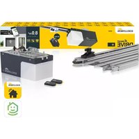
21240 - Smart Home Schellenberg - Free user manual and instructions
Find the device manual for free 21240 Schellenberg in PDF.
User questions about 21240 Schellenberg
0 question about this device. Answer the ones you know or ask your own.
Ask a new question about this device
Download the instructions for your Smart Home in PDF format for free! Find your manual 21240 - Schellenberg and take your electronic device back in hand. On this page are published all the documents necessary for the use of your device. 21240 by Schellenberg.
USER MANUAL 21240 Schellenberg
natural_image
Technical line drawing of a mechanical component with a long rod and cable, no text or symbols presentDE GB FR NL PL IT ES PT CZ SK HU HR SI RO BG
GR TR RU UA LT LV EE SE DK NO FI AL BA XS IS
Deutsch 4
English 10
Français 16
Nederlands 22
Polski 28
Italiano 34
Español 40
Português 46
Český 52
Slovenčina 58
Magyar 64
Hrvatski 70
Slovenski jezik 76
Roman 82
Български 88
Ελληνικά 94
Türk 100
Русский 106
Український 112
Lietuvos 118
Latvijas 124
Eesti 130
Svenska 136
Dansk 142
Norsk 148
Suomi 154
Shqiptar 160
Bosanski 166
Српски 172
Icelandic 178
INHALTSVERZEICHNIS
Safety and notices 11
Technical data 12
Cable connector 13
Accessory shutter suspension 13
Accessory wireless remote control 14
Key explanation 14
Required tools 184
Scope of delivery 184
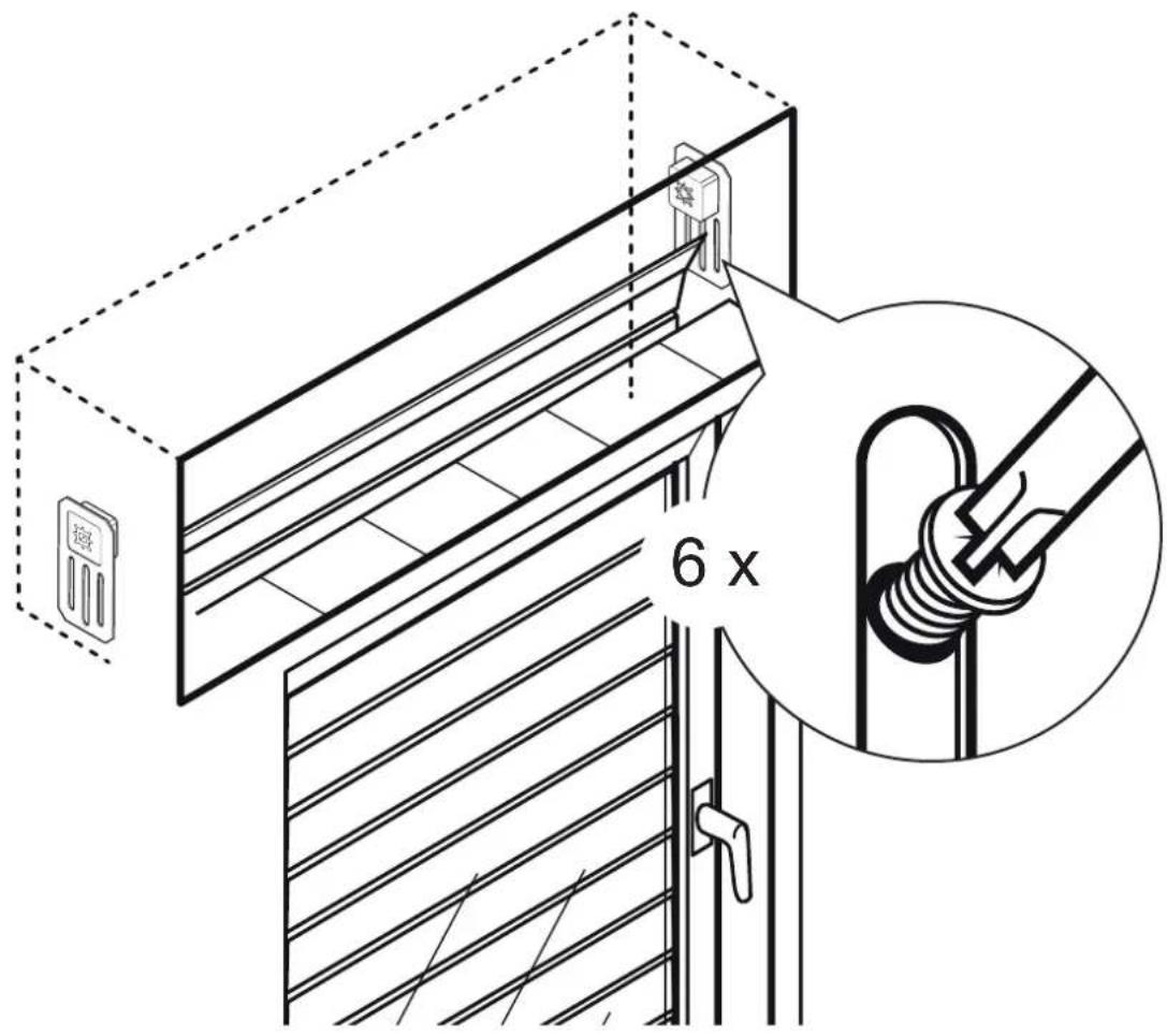
A Installation 185
B Tubular motor address assignment 197
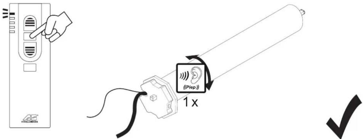
C Programming of tubular motors using a hand-held wireless remote control 200
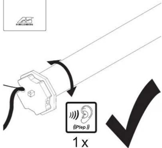
D Programming mode start 201
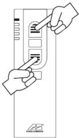
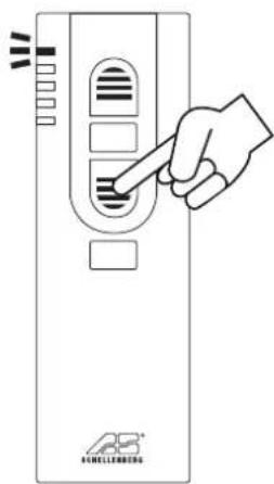
E Pairing the hand-held wireless remote control with the tubular motor 201
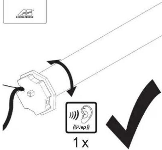
F Tubular motor rotation check 203
G Tubular motor direction change 204
H Setting the upper end position 205
I Setting the lower end position 206
J Concluding the programming mode 207
K Test movement 207
L Pairing further tubular motors 208
SAFETY AND NOTICES
Dear customers,

please completely read this instruction manual before the installation and commissioning. Observe all safety instructions before you begin executing any work. Keep the instruction manual stored at hand and advise each user about possible dangers that are related to this product. In case of a change in ownership pass on the instruction
manual to the new owner. In case of damages which are caused by misuse or improper installation the warranty and any warranty claim will be void.
SAFETY INSTRUCTIONS
There is danger to life from electric shock!

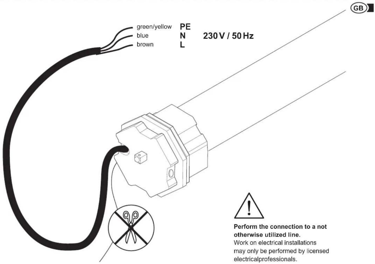
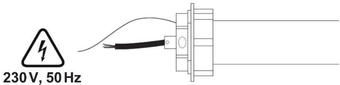
Before working on electrical equipment, the facility must be de-energized. This also applies for the maintenance and repair of the motorized awning system. Work on electrical installations may only be performed by licensed electrical professionals. The provisions of the local electric utility company as well as all applicable standards and regulations for electrical installations must be complied with.
- Before working on roller shutter systems, the shutters must be secured against a self-actuated falling down.
- Only use the tubular motor in dry rooms (protection class IP44).
- The tubular motors become very hot during normal operation. Caution, risk of injury!
- The connecting cable of the tubular motors may not be installed outdoors.
- The tubular motor and the packaging are not toys. Keep children away from them. There is a danger of injury and suffocation.
- During the adjustment process third parties must be kept away from the shutter system.
- The tubular motors may not be opened.
- The tubular motors are maintenance free and do not require any special care.
- The cover of the shutter box should be installed in such a way, that an access is possible at any time.
- Inspect the tubular motor prior to installation for damage and completeness of the accessories.
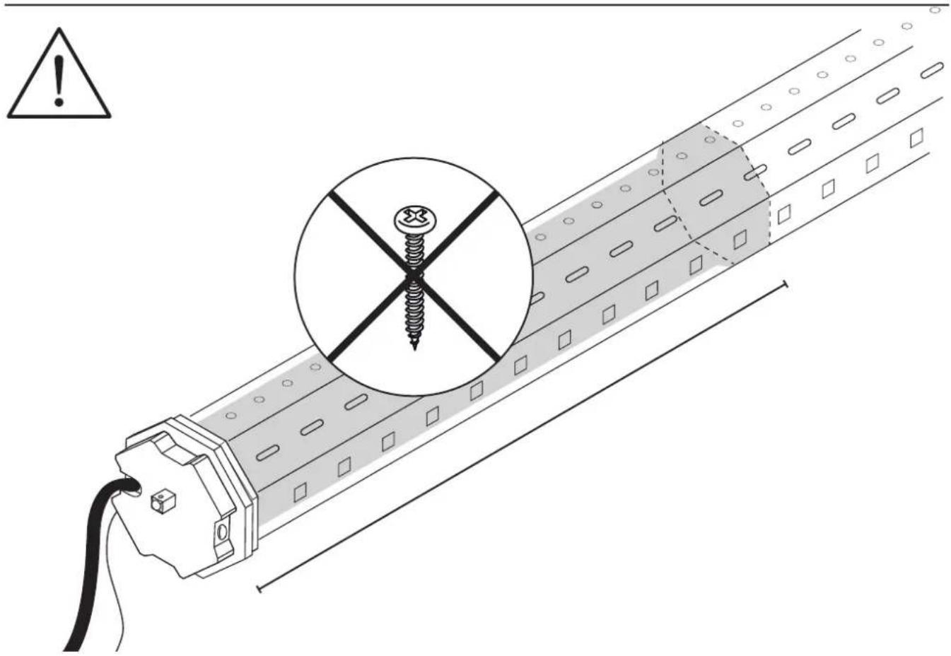
- The tensile load and the dimensioning of the tubular motor must be adapted to the shutter system. The permitted load of the tubular motor may not be exceeded.
- The tubular motors are designed for short-term operation with a duty cycle of 4 minutes. In case of overheating due to long operating times or a too high tensile load, the motor will stop. After a cooling period of at least 15 minutes, the tubular motor will be ready for operation again.
- Check the shutter system regularly for smooth running and for freezing in winter.
- If you have technical questions about your shutter system, please contact our customer service.
- During operation, small variations in the end-position can occur due to temperature differences during the winter and summer. If necessary, a further fine tuning of the final positions may be necessary.
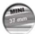
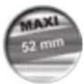
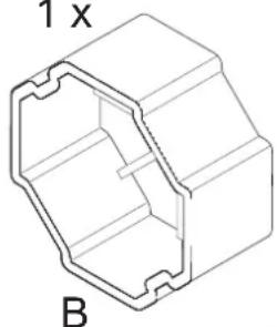
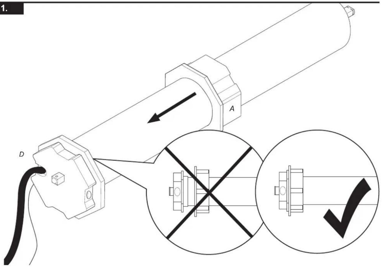
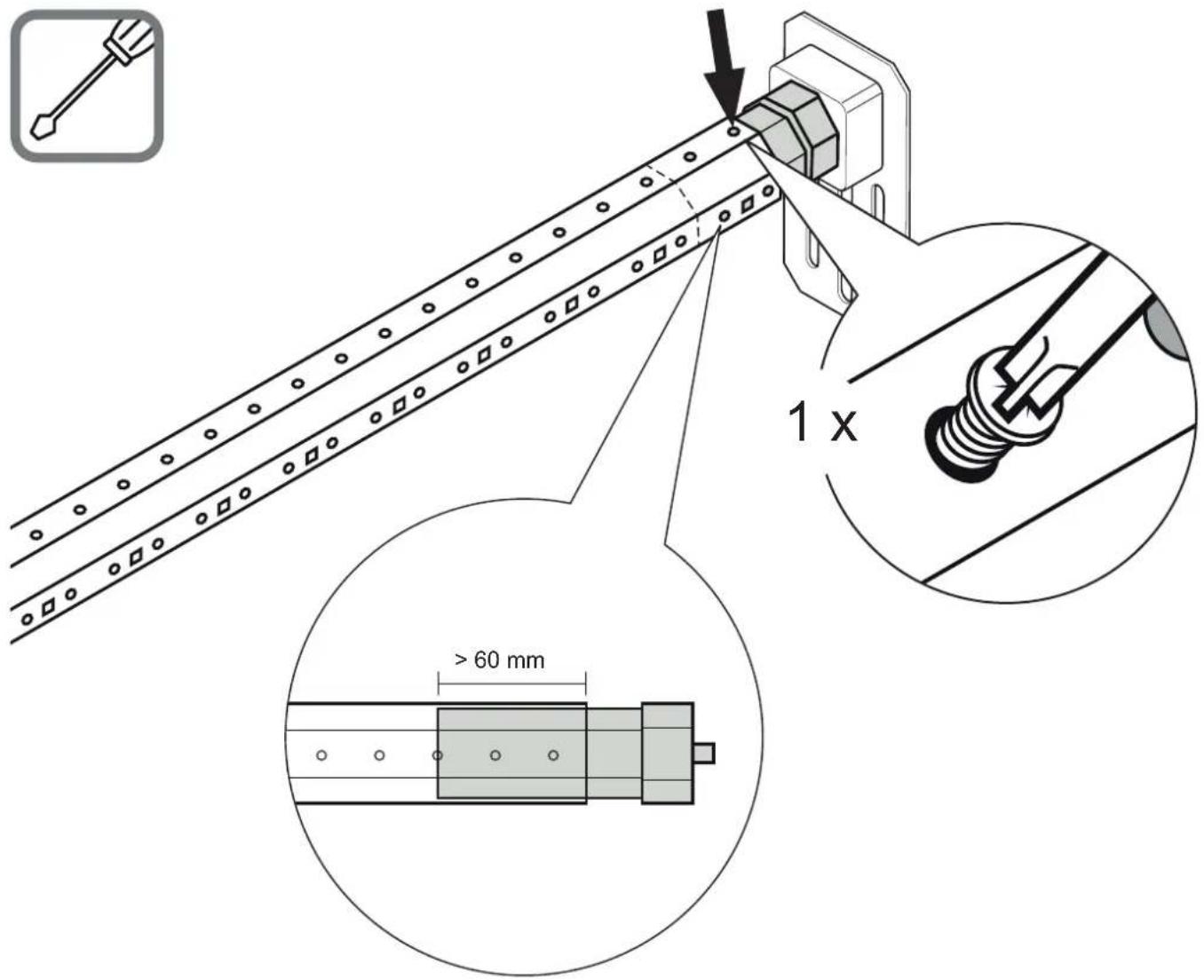
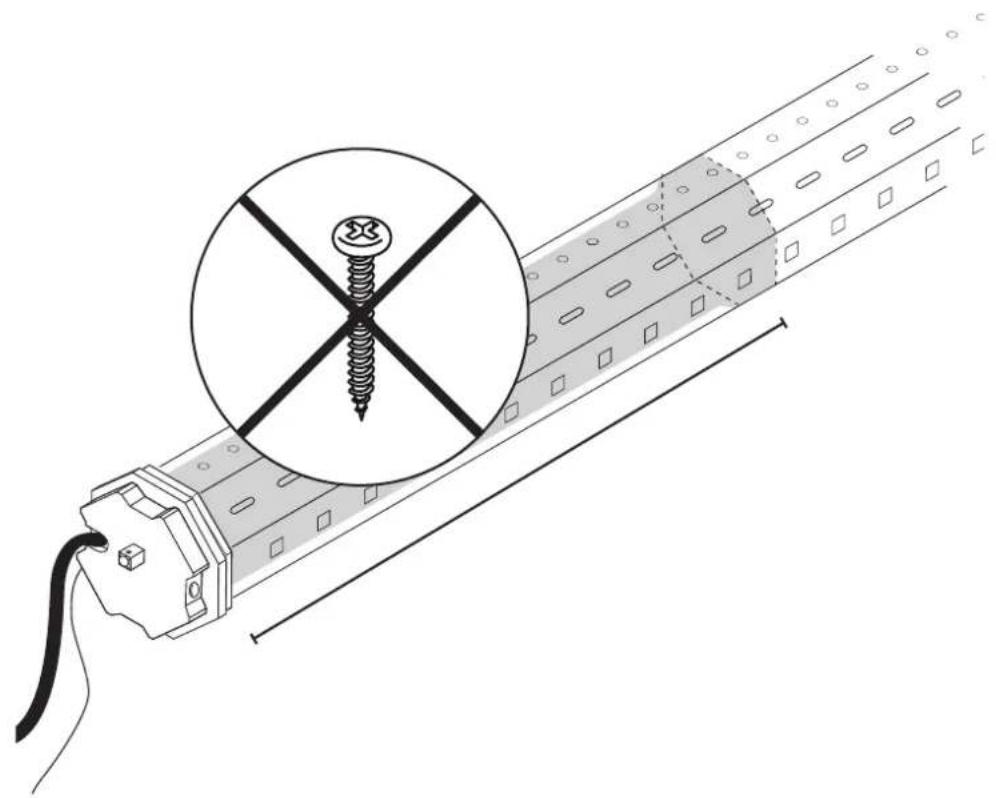
- Equalize length tolerances of the octagonal shaft with a suitable roller sleeve [item-no. 80100 (MINI), item-no. 80200 (MAXI)].
- The roller sleeve must be inserted at least 60 mm deep into the octagonal shaft (page 194). It may not touch the tube motor in the octagonal shaft or obstruct the motion.
INTENDED USE
- The tubular motors are designed exclusively for use in roller shutter systems.
- The tubular motors may only be used in properly assembled roller shutter systems.
- The roller shutter systems must be in a flawless condition.
- Defects of the roller shutter systems must be resolved before the installation of tubular motors, and damaged parts must be replaced.
- Using the tubular motor for purposes other than those mentioned above is considered contrary to its designated use.
- The Alfred Schellenberg GmbH shall not be liable for any consequential damage, property damage and personal injury due to improper use.
The tubular motor meets (item no. 20506/20510/20810/20820/20840/20507/20511/20811) the applicable requirements of the European and national guidelines. The conformity was evidenced and the relevant documents have been filed with the manufacturer.
Do not dispose of together with household waste! The tubular motors are recyclable and can be deposited at a recycling center or a collection station for electrical household garbage.
WARRANTY CONDITIONS
We guarantee that our products are free from material and manufacturing defects. Excluded from the warranty are damages that are caused by:
■ use-related, normal wear and tear
- improper installation, connection, operation or treatment
■ acts of God or other external influences
- improper maintenance and repairs by third parties
■ technical modifications by third parties
In case of a warranty case at our discretion we will repair the product, or exchange it for an equivalent SCHELLENBERG product. Replacement or repair of the unit will not extend the warranty period! A condition for a warranty claim processing is the presentation of the original sales receipt. When shipping the units please include a copy of the original sales receipt and a description of the defect.
We grant a warranty for the quality of our tubular motors from the date of purchase, for a period of: 5 years, item no. 20506/20510/20810/20820/20840/20507/20511/20811.
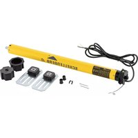
TECHNICAL DATA
| Item no. | 20506/20507 | 20510/20511 | 20810/20811 | 20820 | 20840 |
| Shutter system Mini Mini Maxi Maxi Maxi | |||||
| ∅ octagonal shaft | 40 mm | 40 mm | 60 mm | 60 mm | 60 mm |
| Torque | 6 Nm | 10 Nm | 10 Nm | 20 Nm | 40 Nm |
| max. duty cycle | 4 minutes | 4 minutes | 4 minutes | 4 minutes | 4 minutes |
| max. Flat plastic roller shutters | 4,0 m^2 | 6,0 m^2 | 4,2 m^2 | 8,5 m^2 | 15 m^2 |
| Tensile force | 15 kg | 25 kg | 20 kg | 34 kg | 60 kg |
| Rated power | 98 watts | 121 watts | 113 watts | 161 watts | 218 watts |
| End-position adjustment | Radio Radio Radio Radio | Radio | |||
| incl. wall bearing | 1 Comfort-Set | 1 Comfort-Set | 1 Comfort-Set | 1 Comfort-Set | 1 Comfort-Set |
| Warranty | 5 years | 5 years | 5 years | 5 years | 5 years |
| max. Installation length | 550 mm | 550 mm | 550 mm | 550 mm | 550 mm |
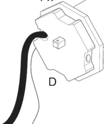
CABLE CONNECTION
ACCESSORIES: SHUTTER SUSPENSION
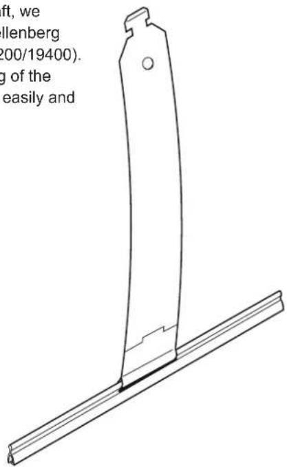
To mount the paneling to the shaft, we recommend the use of the Schellenberg shutter suspension (item no. 19200/19400). This allows for a secure mounting of the shutter panel into the shaft. Very easily and without screw connections.
19200
19400
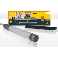
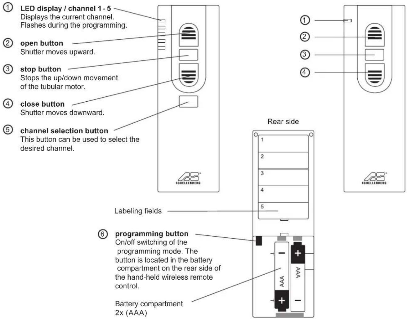
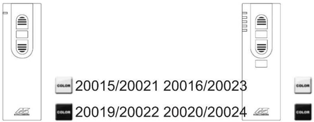
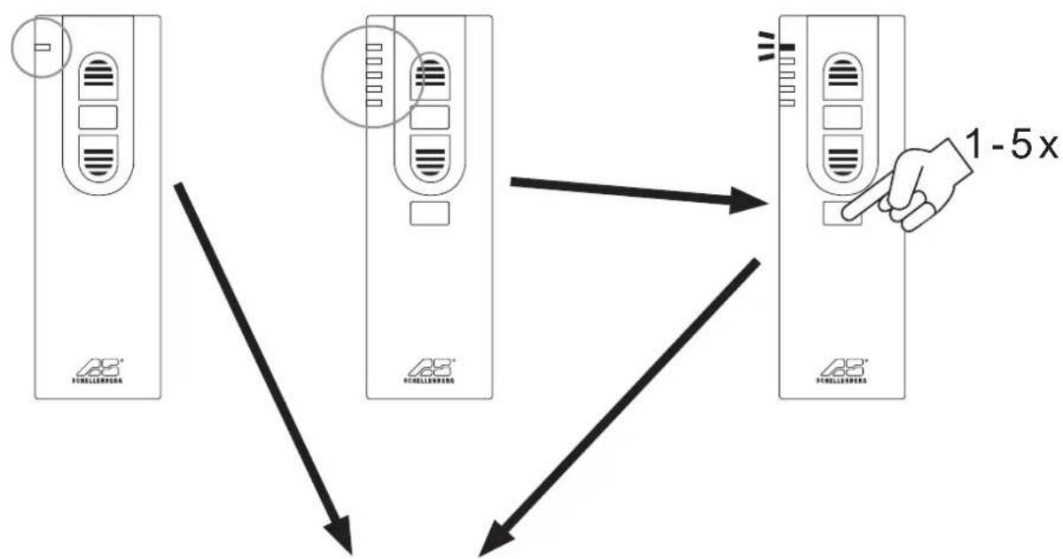
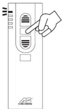
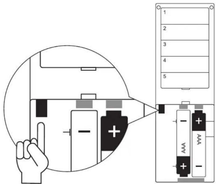
ACCESSORIES: HAND-HELD WIRELESS REMOTE CONTROL

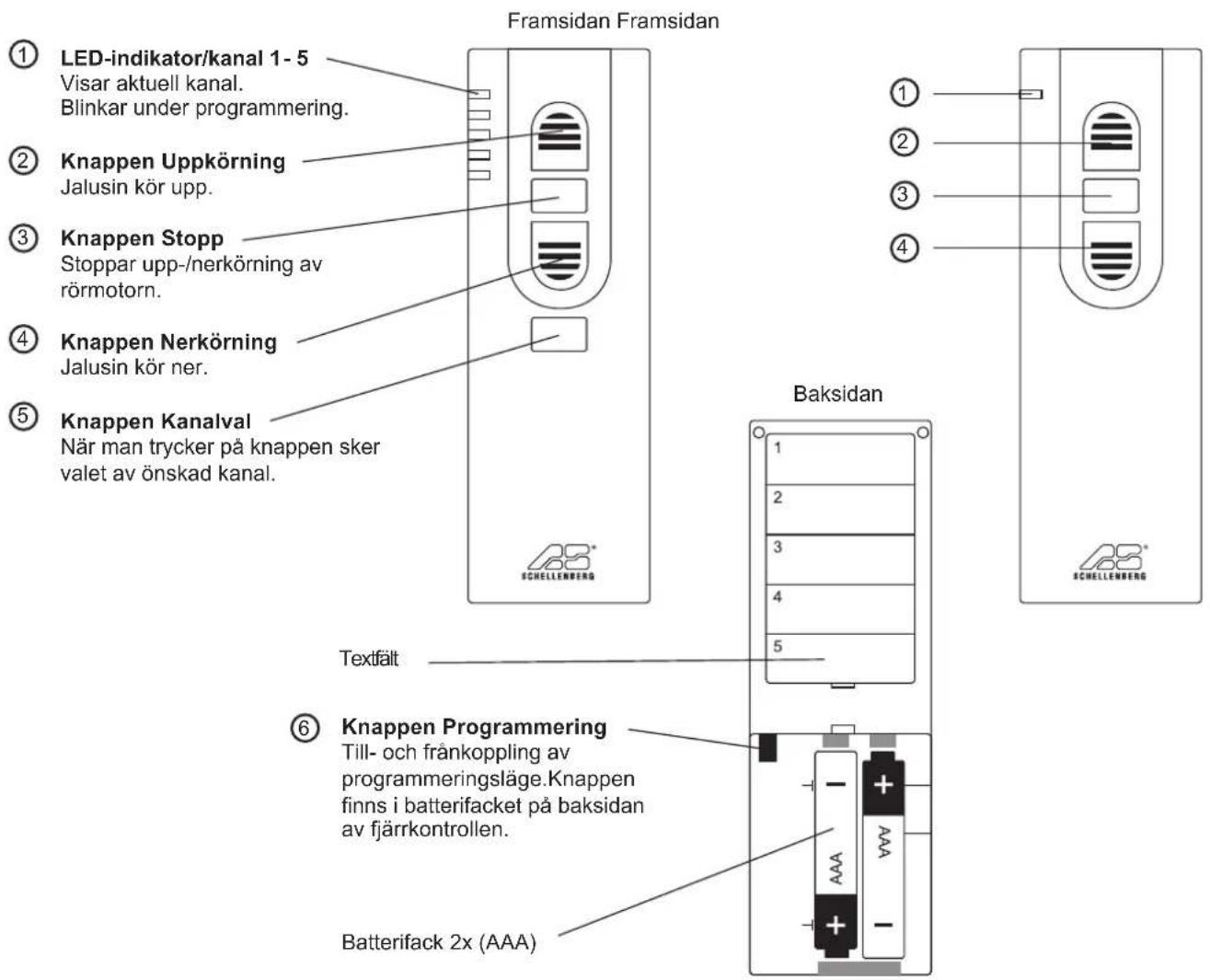
The programming of the tubular motor is performed with the hand-held wireless remote control (accessory). Suitable hand-held wireless remote controllers: 1-channel: 20015/20019/20021/20022 or 5-channel: 20016/20020/20023/20024.
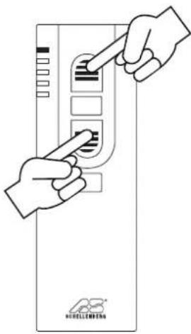
KEY EXPLANATION
5-channel 1-channel
Front side Front side
1-channel
flowchart
graph TD
    A["M1"] --> B["M2"]
    B --> C["M3"]
    C --> D["M4"]
    D --> E["M5"]
    E --> F["1K Device"]
    style A fill:#f9f,stroke:#333
    style B fill:#f9f,stroke:#333
    style C fill:#f9f,stroke:#333
    style D fill:#f9f,stroke:#333
    style E fill:#f9f,stroke:#333
    style F fill:#ccf,stroke:#333
    K1 -.-> A
    K1 -.-> B
    K1 -.-> C
    K1 -.-> D
    K1 -.-> E
    K1 -.-> F
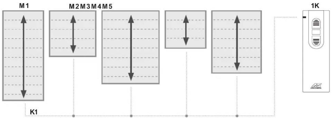
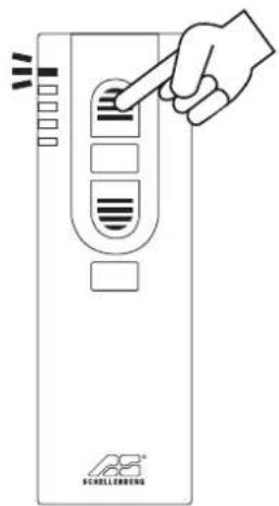
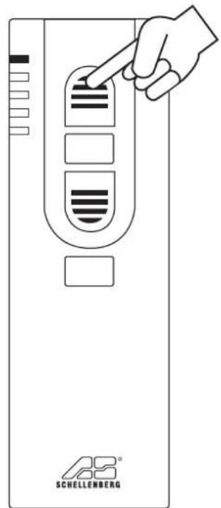
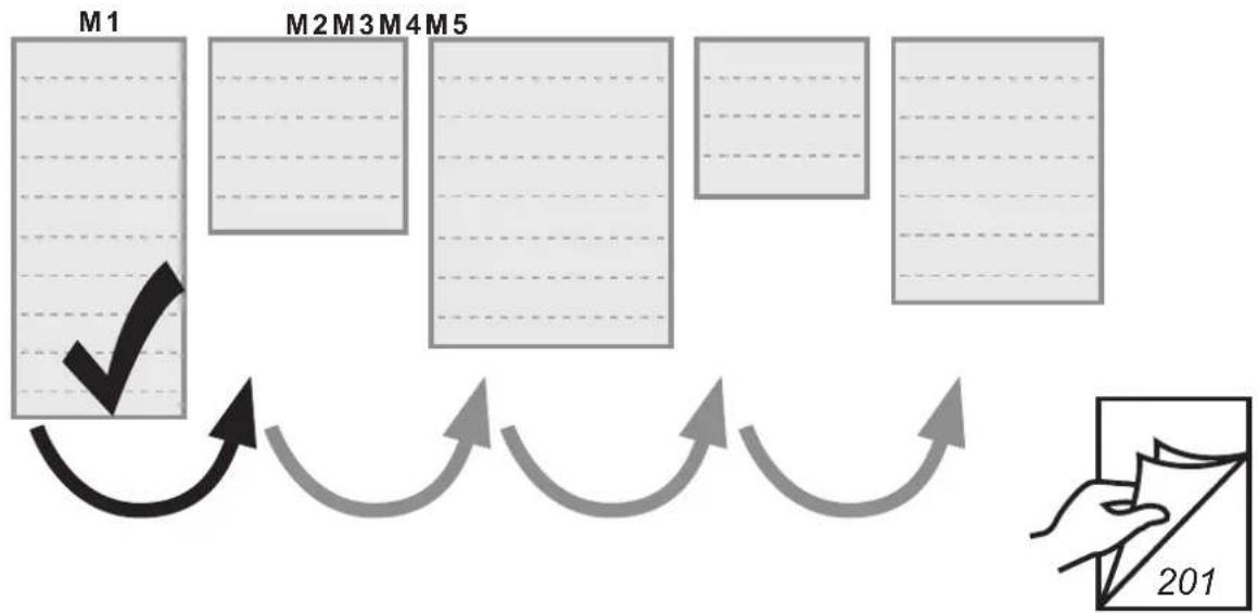
- Depending on the channel, up to five tubular motors can be controlled simultaneously
- by pressing the up-function button all tubular motors will perform an upward movement at the same time
- by pressing the down-function button all tubular motors will perform a downward movement at the same time
- die Endlagen bei den Rollläden können individuell eingestellt werden
M = roller shutter motor
K = channel
5-channel
flowchart
graph TD
    M1["Module M1"] --> K4["K4"]
    M2["Module M2"] --> K3["K3"]
    M3["Module M3"] --> K2["K2"]
    M4["Module M4"] --> K1["K1"]
    M5["Module M5"] --> K1
    K1 --> 5K["5K Device"]
    style M1 fill:#f9f,stroke:#333
    style M2 fill:#f9f,stroke:#333
    style M3 fill:#f9f,stroke:#333
    style M4 fill:#f9f,stroke:#333
    style M5 fill:#f9f,stroke:#333
    style 5K fill:#ccf,stroke:#333
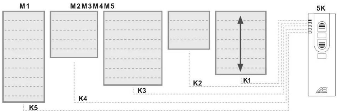
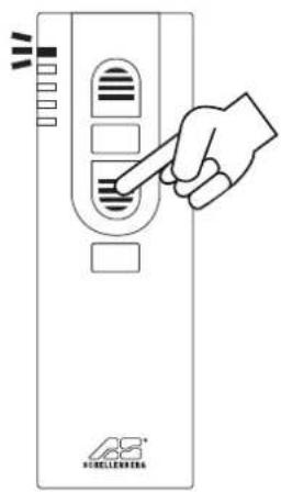
■ Depending on the channel, up to five tubular motors can be controlled simultaneously
- pressing the channel selection button allows a switching between the tubular motors
- by pressing the up-function button the respective tubular motor will perform an upward movement
- by pressing the down-function button the respective tubular motor will perform a downward movement
M = roller shutter motor
K = channel
TABLE DES MATIÈRES
Chers clients, chères clientes,

DÉCLARATION CE ET CONFORMITÉ
CONDITIONS DE GARANTIE
ODGOVARAJUĆA UPORABA
GARANTIJAS NOSACĪJUMI
INNEHÅLLSFÖRTECKNING
BESKRIVNING AV KNAPPARNA
5 kanal 1 kanal
SIGURNOST I INFORMACIJE
Poštovani kupče,

molimo Vas da prije montaže i puštanja u rad u potpunosti pročitate ove upute. Obratite pažnju na sve sigurnosne napomene, prije nego započnete s radom. Sačuvajte ove upute i svakog korisnika upozorite na eventualne opasnosti koje su povezane s ovim proizvodom. Upute u slučaju promjene vlasnika predajte novom vlasniku. Štete uzrokovane nepravilnim korištenjem ili nepravilnom instalacijom poništit će jamstvo i bilo kakve jamstvene zahtjeve.
SIGURNOSNE NAPOMENE
natural_image
Technical line drawing of a mechanical component with a vertical shaft and flange (no text or symbols)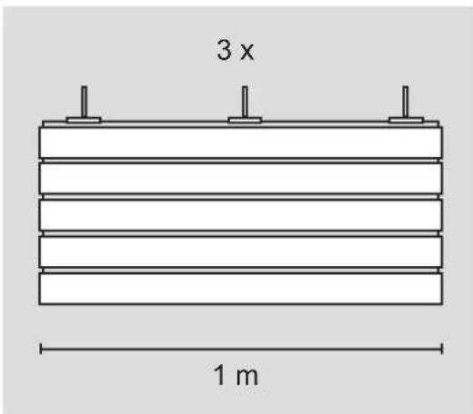
АРТИКЛ ПРИБОРА: РУЧНИ ОДАШИЛЬАЧ

natural_image
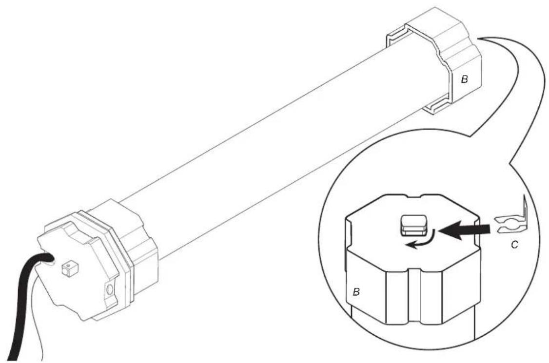
Technical line drawing of a hexagonal bolt head (no text or symbols)1 x
natural_image
Technical line drawing of a hexagonal mechanical part with labeled section 'B' and dimension marker '1 x' (no text or symbols beyond labels)1 x
natural_image
Diagram of a plug with a black cable and labeled point D (no text or symbols beyond label)1 x
1 x
natural_image
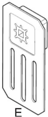
Line drawing of a device with a gear symbol and label 'E' (no text or symbols on the diagram itself)1 x
natural_image
Simple line drawing of a three-pin electronic component with a sun symbol on top (no text or labels)A
1.
2.
3.
natural_image
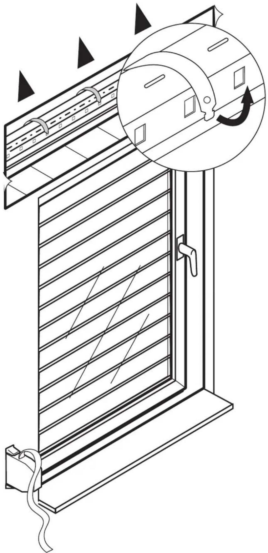
Technical line drawing of a door with horizontal slats and a circular inset showing the mechanism (no text or symbols)4.
natural_image
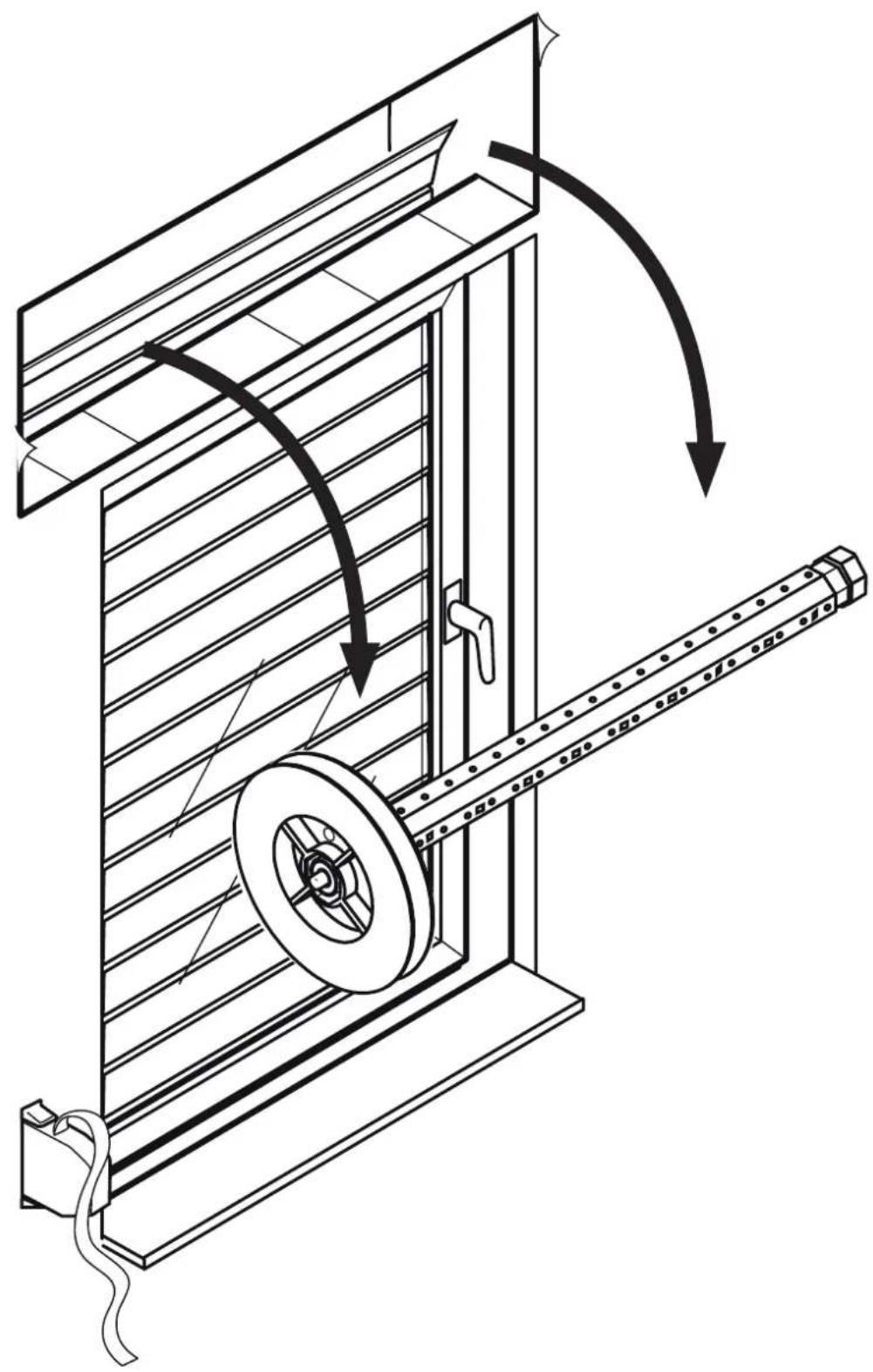
Technical line drawing of a mechanical device with a pulley and rotating shaft, showing motion arrows (no text or symbols)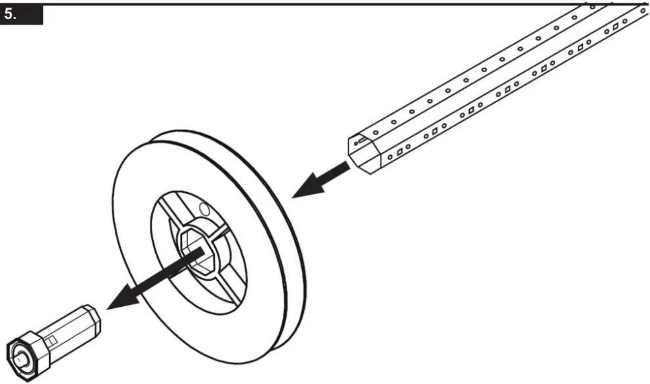
natural_image
Technical illustration of a mechanical assembly showing a pulley and shaft with directional arrows (no text or symbols)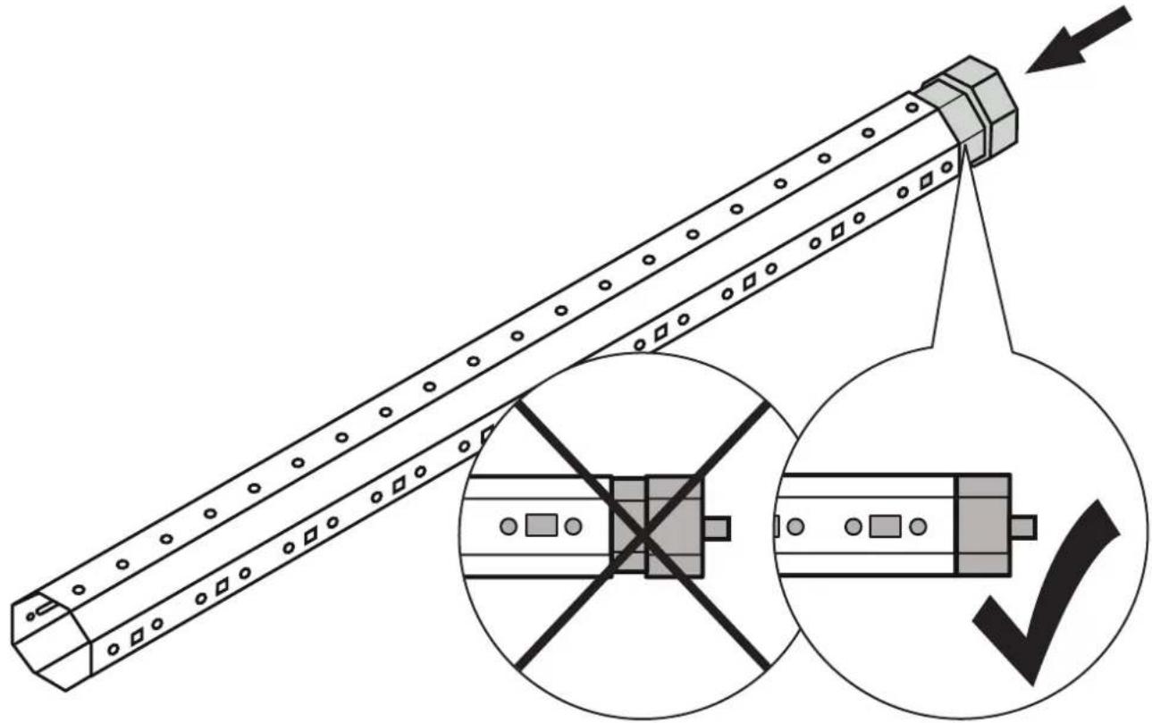
natural_image
Technical illustration of a mechanical component with cross-sectional view and checkmark symbol (no text or labels)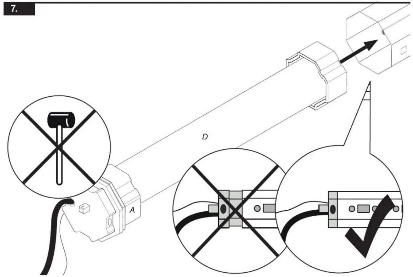

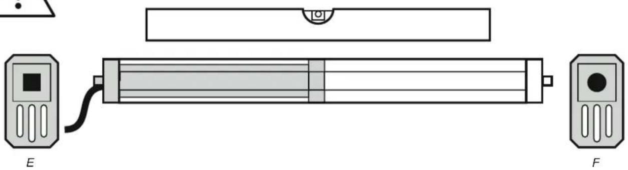
natural_image
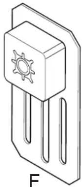
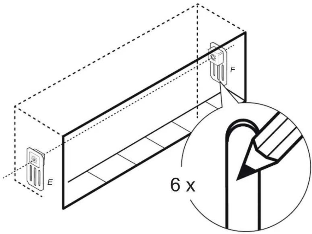
Diagram of a device with labeled components E and F, showing a rectangular component connected to a control panel (no text or symbols beyond labels)
natural_image
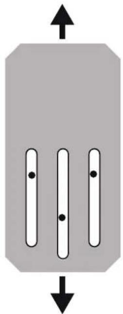
Pure diagram of three vertical bars with dots, no text or symbols present
natural_image
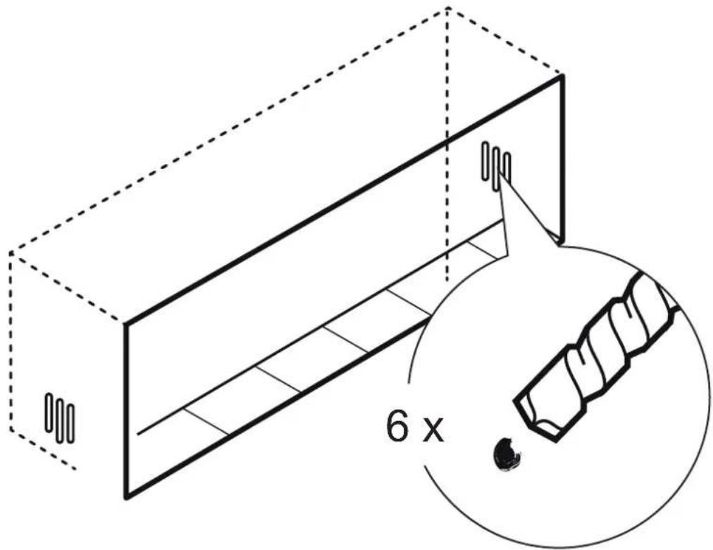
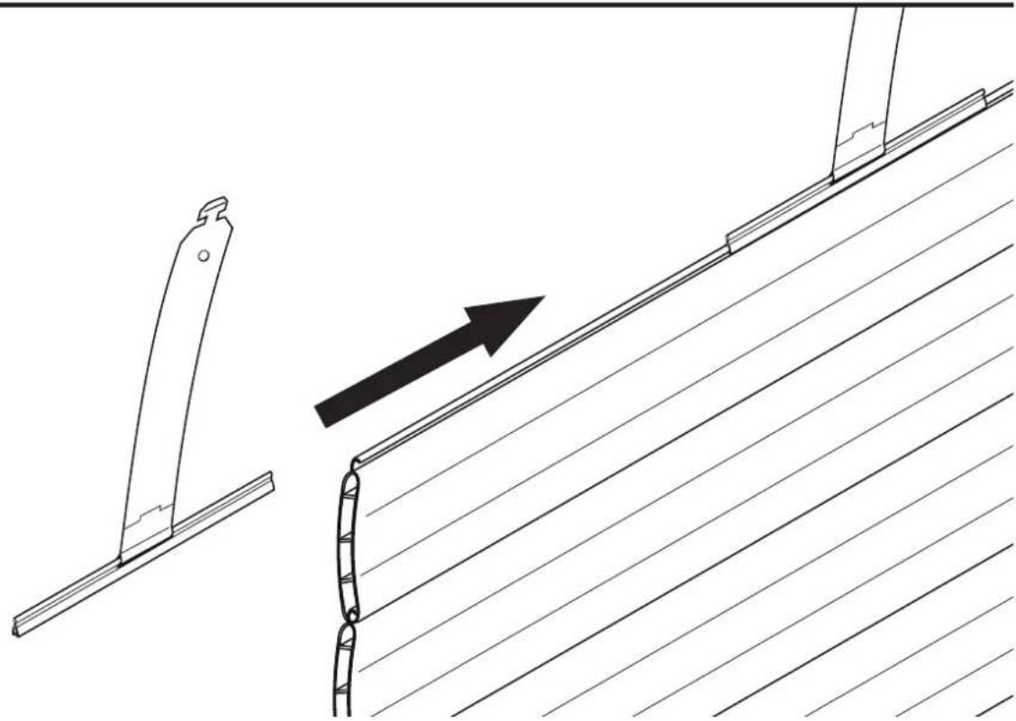
Technical line drawing showing a bracket assembly with an arrow indicating direction (no text or symbols)12.

14.


CP Perform the connection to a not otherwise utilized line.
Work on electrical installations may only be performed by licensed electrical professionals.
natural_image
Technical line drawing of a mechanical assembly with a magnified inset showing internal components (no text or symbols)
natural_image
Technical illustration of a screwdriver with a magnified inset showing the screw and shaft (no text or symbols)B
16.
flowchart
graph TD
    A["3D Machine"] --> B["1"]
    A --> C["2"]
    A --> D["3"]
    A --> E["4"]
    A --> F["5"]
17.
flowchart
graph TD
    A["Device Icon"] --> B["1x1x Frequency Label"]
    B --> C["1x1x1x Frequency Label"]
    C --> D["1x1x1x Frequency Label"]
    D --> E["1x1x1x Frequency Label"]
    E --> F["1x1x1x Frequency Label"]
1 × 2 × 3 × 4 × 5 ×

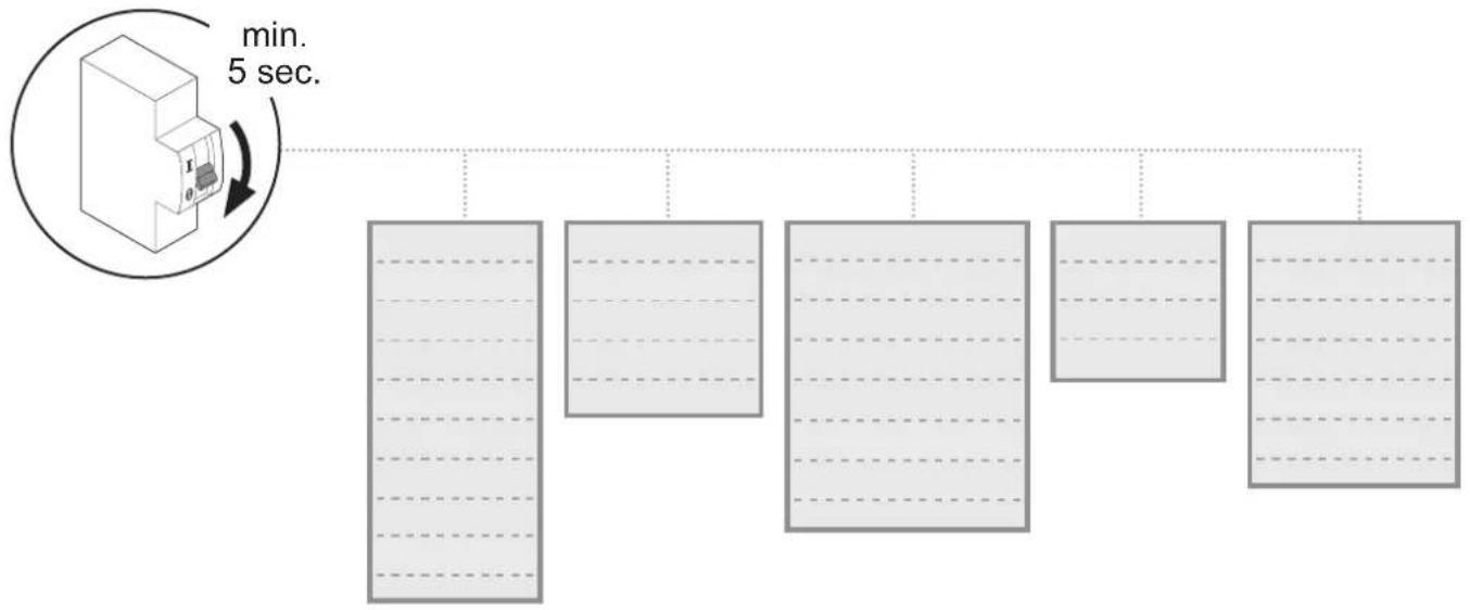
Hinweis:
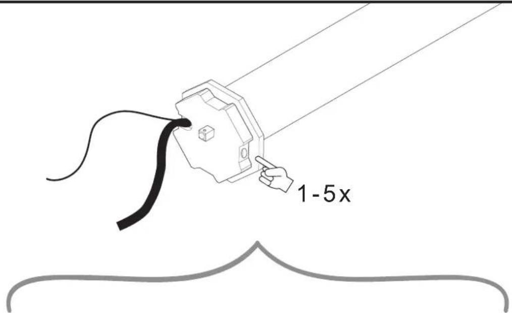
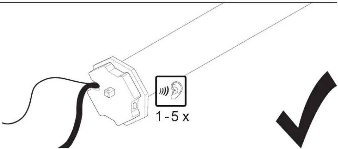
GB Note: We recommend to first assign the respective addresses to the tubular motors before proceeding with the next steps.
E
22.
flowchart
graph TD
    A["Device 1"] --> B["Device 2"]
    B --> C["Device 3"]
    C --> D["Speed Limit: 1-5x"]
    style A fill:#f9f,stroke:#333
    style B fill:#f9f,stroke:#333
    style C fill:#f9f,stroke:#333
    style D fill:#f9f,stroke:#333
23.
natural_image
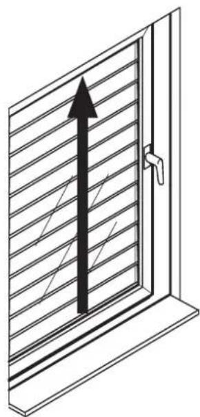
Diagram of a door with diagonal striped pattern and an upward arrow, no text or symbols present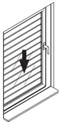
natural_image
Diagram of a window with diagonal striped pattern and a black downward arrow indicating compression or damage (no text or symbols)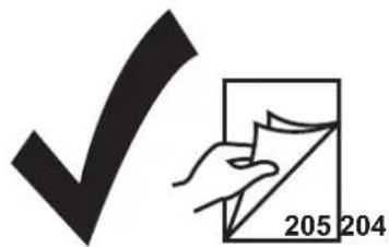

G
27.
28.
H
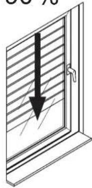
29.
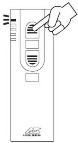
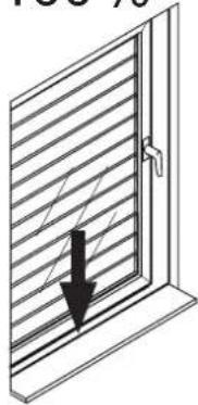
90%
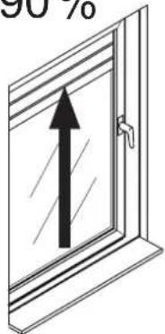
100%
natural_image
Simple line drawing of a door with an arrow pointing upward (no text or symbols)30.
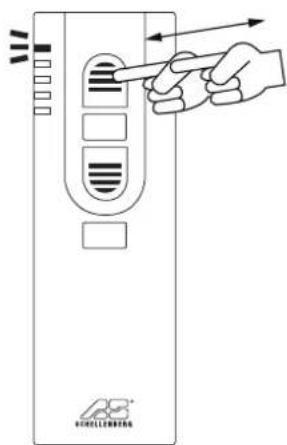
I
90%
natural_image
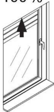
Diagram of a door with horizontal stripes and a black arrow pointing downward (no text or symbols)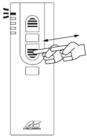
100%
natural_image
Diagram of a window with horizontal slats and a black arrow pointing to the left pan (no text or symbols)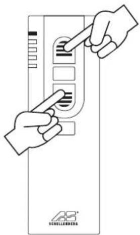
J
35.

natural_image
Black checkmark symbol on white background (no text or additional symbols)K
36.
natural_image
Diagram of a window with diagonal blinds and an upward arrow, no text or symbols present
natural_image
Black checkmark symbol on white background (no text or additional symbols)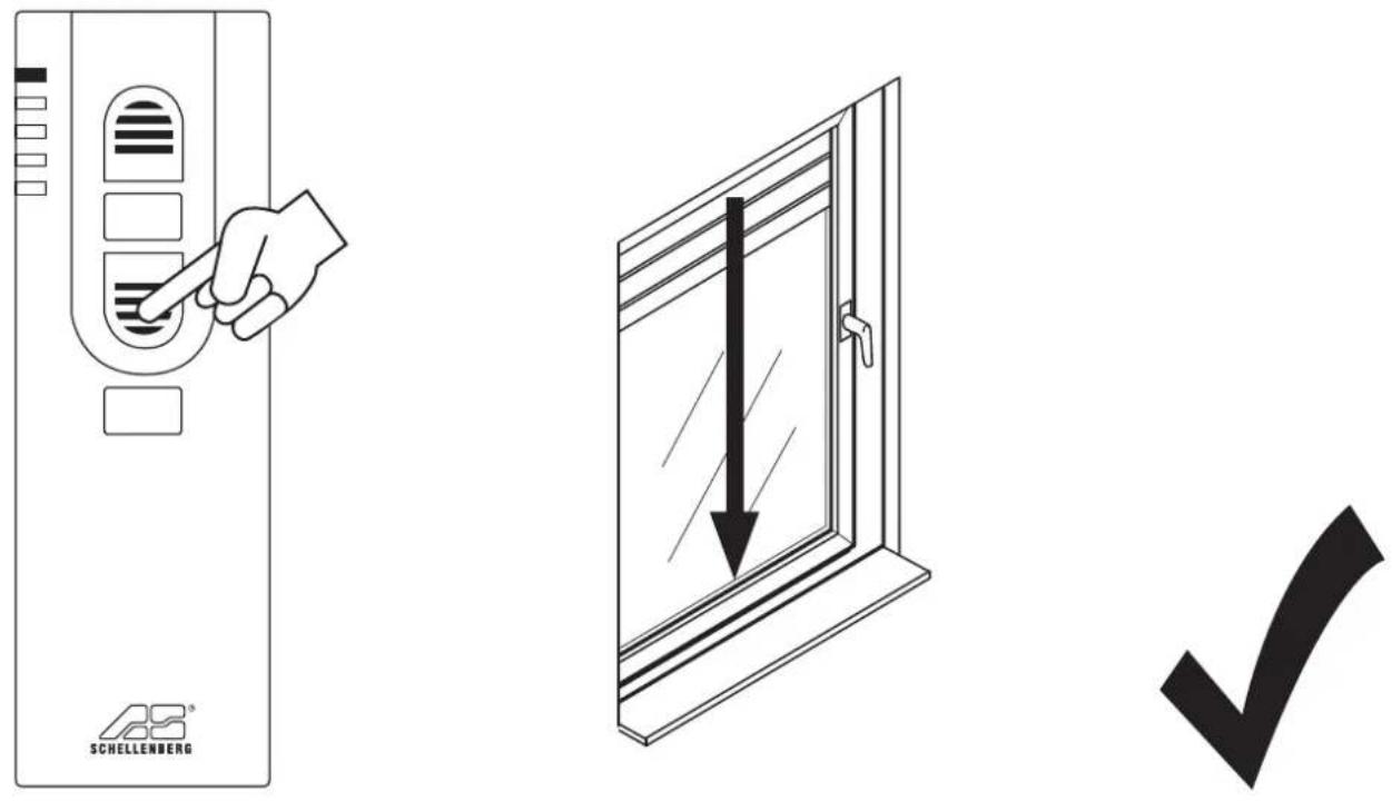
L
flowchart
graph TD
    M1["Module M1"] --> A["Arrow with checkmark"]
    M2["Module M2"] --> A
    M3["Module M3"] --> A
    M4["Module M4"] --> A
    M5["Module M5"] --> A
    A --> B["Arrow with arrow"]
    B --> C["Arrow with arrow"]
    C --> D["Arrow with arrow"]
    D --> E["Arrow with arrow"]
    E --> F["Arrow with arrow"]
    F --> G["Arrow with arrow"]
    G --> H["Arrow with arrow"]
    H --> I["Arrow with arrow"]
    I --> J["Arrow with arrow"]
    J --> K["Arrow with arrow"]
    K --> L["Arrow with arrow"]
    L --> M["Arrow with arrow"]