Duspol Digital - Multimeter BENNING - Free user manual and instructions
Find the device manual for free Duspol Digital BENNING in PDF.
User questions about Duspol Digital BENNING
0 question about this device. Answer the ones you know or ask your own.
Ask a new question about this device
Download the instructions for your Multimeter in PDF format for free! Find your manual Duspol Digital - BENNING and take your electronic device back in hand. On this page are published all the documents necessary for the use of your device. Duspol Digital by BENNING.
USER MANUAL Duspol Digital BENNING
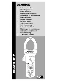
Before using the DUSPOL® digital voltage tester, proceed as follows: Please read the operating manual and absolutely observe the safety instructions!
Table of Contents
-
Safety instructions
-
Device description
-
Functional test before use to ensure the absence of voltage of an installation
-
Checking the absence of voltage of an installation
-
Load connection with vibration motor
-
External conductor test (phase indication)
-
Phase sequence test
-
Continuity test
-
Resistance measurement
-
Diode test
-
Cable break detector
-
Measuring point / display illumination
-
Battery replacement
-
Technical data
-
General maintenance
-
Environmental protection
1. Safety instructions:
- During the use, touch the tester at the insulated handles L1 ⑧ and L2 ⑨ only and do not touch the probe tips L1/- ② and L2/+ ③!
- Check the voltage tester for correct functioning immediately before and after using it in order to ensure the absence of voltage of an installation (see section 3)! Do not use the voltage tester, if one or more indications are not working or if it does not seem to be ready for operation! Please repeat the test with another voltage tester afterwards.
- With the battery being exhausted, the voltage tester is not fully functional! From a voltage of AC/DC ≥ 50 V on, voltage tests are also possible without batteries by means of the LED stop indicator 10. The LC display 6 is activated with a minimum voltage ≥ 150 V AC/DC.
- The voltage tester must be used only within the stated nominal voltage range and in electrical installations of up to 1,000 V AC / 1,200 V DC!
- The voltage tester must be used only in electric circuits of overvoltage category CAT III with max. 1,000 V or overvoltage category CAT IV with max. 600 V for phase-to-earth measurements.
- Do not operate the device with the battery compartment being open.
- The voltage tester is designed for being used by qualified electricians and under safe working conditions.
- The LED step indicator 10 is intended for indicating the voltage range. It is not intended for measuring purposes.
- Creating a voltage tester for more than 30 seconds voltage (maximum duty cycle = 30 s)!
- Do not dismantle the voltage tester!
- The voltage tester must be protected against contamination and damaging of the housing surface.
- To protect them against damaging, provide the probe tips with the enclosed probe tip protector ① after using the voltage tester!
- Please observe that the impedance (internal resistance) of the voltage tester influences the indication of interference voltages (capacitively or inductively induced)! Depending on the internal impedance of the voltage detector, there will be a different capability of indicating the
presence or absence of operating voltage in case of the presence of interference voltage.
Low-impedance voltage tester (impedance < 100 kΩ), interference voltage is suppressed or reduced:
A voltage tester of relatively low internal impedance, compared to the reference value of 100 kΩ, will not indicate all interference voltages having an original voltage value above the ELV level (50 V AC/ 120 V DC). When in contact with the parts to be tested, the voltage tester may discharge temporarily the interference voltage to a level below the ELV, but it will be back to the original value when the voltage tester is removed. When the indication "voltage present" does not appear, it is highly recommended to install earthing equipment before starting work.
High-impedance voltage tester (impedance > 100 kΩ): Interference voltage will not be suppressed or reduced:
A voltage tester of relatively high internal impedance, compared to the reference value of 100 kΩ, may not permit to clearly indicate the absence of operating voltage in case of presence of interference voltage. When the indication "voltage present" appears on a part that is expected to be disconnected from the installation, it is highly recommended to confirm by another means (e.g. use of an adequate voltage tester capable of distinguishing between operating voltages and interference voltages, visual inspection of the disconnecting point of the electric circuit, etc.) that there is no operating voltage on the part to be tested and to conclude that the voltage indicated by the voltage tester is an interference voltage.
Voltage testers capable of distinguishing between operating voltage and Interference voltage by means of load connection:
A voltage tester stating two values of internal impedance has passed a performance test of managing interference voltages and is (within technical limits) able to distinguish operating voltage from interference voltage and has a means to directly or indirectly indicate which type of voltage is present.
Electrical symbols on the device:
| Symbol Meaning | |
| Important documentation!The symbol indicates that the guide described in the manual, to avoid any risks | |
| Device or equipment for working under voltage | |
| Push-button | |
| Alternating voltage (AC) | |
| Direct voltage (DC) | |
| Direct and alternating voltage (DC/AC) | |
| Earth (voltage to ground) | |
| Phase sequence indication; the phase sequence can be indicated only at 50 or 60 Hz and in an earthod mains | |
| This symbol shows the orientation of the batteries for inserting them with correct polarity | |
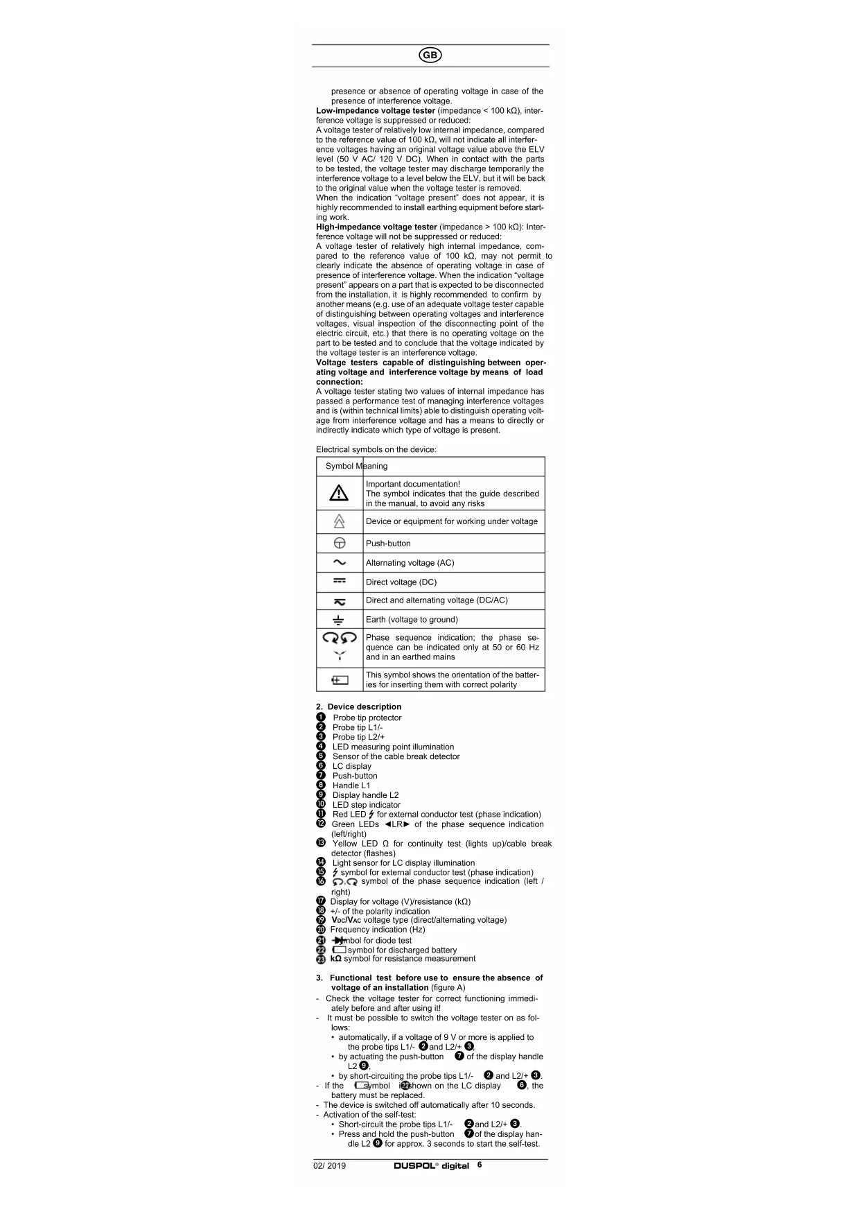
- Device description
1 Probe tip protector
② Probe tip L1/-
3 Probe tip L2/+
4 LED measuring point illumination
5 Sensor of the cable break detector
8 LC display
7 Push-button
B Handle L
9 Display handle L2
10 LED step indicator
11 Red LED for external conductor test (phase indication)
⑫ Green LEDs ◀LR▶ of the phase sequence indication (left/right)
13 Yellow LED Ω for continuity test (lights up)/cable break detector (flashes)
14 Light sensor for LC display illumination
15 symbol for external conductor test (phase indication)
16 0,0 symbol of the phase sequence indication (left / right)
17 Display for voltage (V)/resistance (kΩ)
18 +/- of the polarity indication
19 Voc/VAC voltage type (direct/alternating voltage)
20 Frequency indication (Hz)
21 Symbol for diode test
22 symbol for discharged battery
23 kΩ symbol for resistance measurement
- Functional test before use to ensure the absence of voltage of an installation (figure A)
- Check the voltage tester for correct functioning immediately before and after using it!
- It must be possible to switch the voltage tester on as follows:
• automatically, if a voltage of 9 V or more is applied to the probe tips L1/- ② and L2/+ ③,
- by actuating the push-button ⑦ of the display handle L2⑨;
- by short-circuiting the probe tips L1/- ② and L2/+ ③.
- If the symbol is shown on the LC display 6, the battery must be replaced.
- The device is switched off automatically after 10 seconds.
- Activation of the self-test:
- Short-circuit the probe tips L1/- ② and L2/+ ③. - Press and hold the push-button ⑦ of the display handle L2 ⑨ for approx. 3 seconds to start the self-test.
- The buzzer sounds and all segments of the LC display, all LEDs (running light) as well as the background and measuring point illumination must be functioning.
- Test the voltage tester with familiar voltage sources, e.g. with a 230 V socket.
- Do not use the voltage tester, if the voltage indication, the phase indication and the vibration motor are not working properly!
4. Checking the absence of voltage of an Installation (figuro B/C)
For checking the installation, please test the absence of voltage by checking the voltage indication, the phase indication (the phase indication only works in an earthed AC voltage mains) and the vibration motor (the vibration motor is activated by actuating both push-buttons). The installation is only free of voltage, if all three test circuits (voltage indication, phase indication and vibration motor) are signaling the absence of voltage.
- Apply the two probe tips L1/+ ② and L2/- ③ to the system parts to be tested.
- The voltage tester switches on automatically as soon as a voltage ≥ 9V is applied.
- The level of voltage applied is indicated by means of the LED step indicator ⑩ and the digital display ⑥. The 400 V LED of the LED step indicator ⑩ covers the voltage range from 400 V AC/DC to 1,000 V AC/1,200 V DC.
- Alternating voltages are indicated by means of the VAC symbol 17 on the LC display 6. Additionally, the frequency 20 of the AC voltage applied is displayed.
- Direct voltages are indicated by means of the VDC symbol 19 on the LC display 6. Additionally, the polarity indication 18 shows the polarity (+ or -) applied to the probe tip L2/+ 3.
- To differentiate between low-energy and high-energy voltages (e.g. capacitively induced interference voltages), an internal load in the voltage tester can be connected by actuating both push-buttons (see section 5).
Voltage test < 6 V (low-volt) (figure D)
In order to measure voltages lower than 6 V, short-circuit the probe tips L1/- and L2/+ and press the push-button of the display handle L2 three times until the "Lo U" symbol is shown on the LC display
In the low-volt range, voltages from 1.0 V to 11.9 V can be measured.
- After being activated, the low-volt range is active for approx. 10 seconds.
- By applying a voltage ≥ 12 V, the device automatically switches over to a higher voltage range.
Note:
In the low-volt range, the frequency indication 70 is deactivated.
Overload Indication
If the voltage applied to the probe tips L1/- ② and L2/+ ③ is higher than the admissible nominal voltage, the „OL“ symbol is shown on the LC display ⑥ and all LEDs of the stop indicator ⑩ are flashing. Overload is indicated from 1,050 V AC, 1,250 V DC on.
5. Load connection with vibration motor (figure B/C)
Both handles L1 8 and L2 9 are equipped with push-buttons 7. Here, voltage is applied to a vibration motor (motor with unbalanced mass) in the display handle L2 8. From approx. 200 V on, this motor is set in rotary motion. With the voltage increasing, the motor's speed and vibration increases as well. The duration of the test with a lower internal resistance (load test) depends on the level of voltage to be measured. In order to avoid an inadmissible warming of the device, it is provided with a thermal protection (controlled reduction). With this controlled reduction, the speed of the vibration motor is reduced and the internal resistance increases.
The load connection (with both push-buttons being actuated) can be used ...
- to suppress reactive voltages (inductive and capacitive voltages),
- to charge capacitors,
- to trip 10/30 mA RCD safety switches. The tripping of the RCD safety switch is done by testing the external conductor (phase indication) to PE (earth). (figure F)
6. External conductor test (phase indication) (figure E)
- Fully grasp the handles L1 8 and L2 9, in order to ensure a capacitive coupling to earth.
- Switch the voltage tester on by briefly actuating the push-button ⑦ of the display handle L2 ⑨ (remains switched on for approx. 10 seconds!). When the device is switched on, the display shows .0.0".
- Apply the probe tip L2/+ ③ to the system part to be tested. During the single-pole external conductor test (phase indication), make absolutely sure not to touch the probe tip L1/- ② and that it remains contactless.
- If the red LED 11 and the 7 symbol 15 light up on the LC display 8, the external conductor (phase) of an AC voltage is applied to this system part.
Note:
The single-pole external conductor test (phase indication) can be carried out in an earthed mains from 230 V, 50/60 Hz (phase to earth) on. Protective clothing and insulating conditions on site might impair the function.
Attention!
The absence of voltage can only be determined by means of a two-pole test.
7. Phase sequence test (figure G/H)
- Fully grasp both handles L1 8 and L2 9, in order to en-
sure a capacitive coupling to earth.
- Apply the probe lips L1/- ② and L2/+ ③ to two external conductors (phases) and check whether the external conductor voltage of e.g. 400 V is applied.
- A clockwise phase sequence (phase L1 before phase L2) is given, if the green LED ▶ of the phase sequence indication ⑫ and the ○ symbol of the phase sequence indication ⑯ light up on the LC display ⑪.
- A counter-clockwise phase sequence (phase L2 before phase L1) is given, if the green LED "◀" of the phase sequence indication 12 and the symbol of the phase sequence indication 16 light up on the LC display 6.
- The phase sequence test always requires a countercheck with the probe tips L1/- ② and L2/+ ③ being inverted during which the phase sequence must change.
Note:
The phase sequence test can be carried out in an earthed three-phase mains from 400 V - 900 V, 50/60 Hz (phase to phase) on. Protective clothing and insulating conditions on site might impair the function.
8. Continuity test (figure I)
- The continuity test must be carried out on system parts which are free of voltage. If necessary, capacitors have to be discharged.
- Apply the two probe tips L1/- ② and L2/+ ③ to the system parts to be tested.
- In case of continuity (R < 100 kΩ), an acoustic signal is emitted and the yellow LED Ω ⑬ for continuity lights up.
- If a voltage is applied to the test point, the voltage tester automatically switches over to the voltage test function and indicates this function.
9. Resistance measurement (figure J)
- The resistance measurement must be carried out on system parts which are free of voltage. If necessary, capacitors have to be discharged.
- Short-circuit the probe tips L1/- ② and L2/+ ③ and pross the push-button ⑦ of the display handle L2 ⑨ once until the kΩ symbol and "Ohm" are shown on the LC display ⑥. Display: "OL" stands for a measured value which is outside the measuring range.
- The resistance measurement function is active for approx. 10 seconds.
- Apply the probe tips L1/- ② and L2/+ ③ to the system parts to be tested in order to measure resistances from 0.1 kΩ to 300 kΩ.
Note:
If required, it is possible to carry out a null balance with the resistance measurement function being activated. For this purpose, short-circuit the probe tips L1/-2 and L2/+3 and press and hold the push-button 7 of the display handle L2 9 for approx. 2 seconds until „0.0“ kΩ is shown on the LC display.
10. Diode test (figures K/L)
- The diode test must be carried out on system parts which are free of voltage. If necessary, capacitors have to be discharged.
- Short-circuit the probe tips L1/- ② and L2/+ ③ and press the push-button ⑦ of the display handle L2 ⑨ twice until the diode symbol → an ⑪ diod* are shown on the LC display ⑥ Display: "OL" VDC
- The diode test is active for approx. 10 seconds.
- Apply the probe tip L1i- ② to the cathode and the probe tip L2/+ ③ to the anode of the diode to determine the conducting-state voltage between 0.3 V and 2 V. In case of a defective (broken down) diode, a voltage value of approx. 0.0 V will be displayed.
- In case of a diode tested in non-conducting direction, the LC display shows „OL“.
11. Cable break detector (figure M)
- The cable break detector is intended for the non-contact localization of cable breaks on exposed live lines.
- Switch the voltage tester on by briefly actuating the push-button 7 of the display handle L2 9 (remains switched on for approx. 10 seconds!). When the device is switched on, the display shows ,0.0".
- Fully grasp the display handle L2 ⑨ and pass the detector ⑤ over a live line (e.g. a cable reel or a chain of lights) from the feeding point (phase) in direction of the other end of the line.
- As long as the line is not interrupted, the yellow LED Ω for continuity is flashing.
- The point of the cable break has been localized as soon as the yellow LED Ω 13 goes out.
Note:
The cable break detector may grounded power from 230 V, 50/60 Hz (phase to earth) are used. Insulating protective clothing and site conditions can affect the function.
12. Measuring point/display illumination (figure N)
- The measuring point illumination ④ can be switched on with the probe tips being open by actuating the push-button ⑦ of the display handle L2 ⑨ (1 second).
- The off automatically after 10 seconds
- The background lighting of the LC display 6 is activated automatically by means of a light sensor 14.
13. Battery replacement (figure O)
- Do not apply voltage to the device when the battery compartment is open!
- Please replace the batteries as soon as the □ symbol 22 is shown on the LC display 6.
- The battery compartment is located on the back of the display handle L2/+ 9.
-
Unscrew the screw of the battery compartment cover and replace the used batteries by two new micro batteries (LR03/AAA).
-
Make sure that the new batteries are inserted with correct polarity!
- Place the battery compartment cover onto the display handle L2 ⑨ and tighten the screw.
14. Technical data
- regulation: DIN EN 61243-3: 2015, IEC 61243-3: 2014 - nominal voltage range: 1 V to 1,000 V AC TRUE RMS/1,200 V DC
- nominal frequency range f: 0 to 1000 Hz* ^ according DIN EN 61243-3/IEC 61243-3, f: 16 % to 500 Hz - voltage range: 6 V to 1,000 V AC TRUE RMS / 1,200 V DC
resolution 0.1 V (up to 198.9 V), 1 V (from 199 V on)
- voltage range < 6 V (low-volt): 1.0 V to 11.9 V AC / DC resolution 0.1 V
accuracy: ± 3 % of the measured value + 5 digits
- Impedance (internal resistance) of measuring circuit/ load circuit: 188 kΩ/5 kΩ
- current consumption of measuring circuit: I_s < 7.2 mA (1.200 V)
- current consumption of load circuit: I_s < 550 mA (1,000 V) - polarity indication: LCD symbol +/-
- external conductor test (phase indication): ≥ U, 230 V, 50 Hz/60 Hz
- phase sequence test: ≥ U, 400 V, 50 Hz/60 Hz
- continuity test: 0 to approx. 100 kΩ, LED + buzzer. testing current: max. 10 μA
- diode test: 0.3 V to 2.0 V, testing current: max. 10 μA - frequency range: 0 to 1.000 Hz
accuracy: ± 3 % of the measured value + 2 digit
- resistance range: 0.1 kΩ to 300 kΩ, testing current: max. 10 μA
accuracy: ± 10 % of the measured value + 5 digit
- cable break detector: ≥ U 230 V
- vibration motor, start: ≥ U 200 V
- overvoltage category: CAT IV 600 V, ± CAT III 1,000 V - protection category: IP 65 (DIN VDE 0470-1 IEC/ EN 60529) 6 - first index: protection against access to dangerous parts and protection against solid impurities, dustproof
5 - second index: protected against water jets. The device can also be used in the rain.
- max. allowable Duty cycle: 30 s (max. 30 seconds), 240 s off
- device switch-on by means of measuring voltage: ≥ 9 V, by actuating the push-button ⑦ of the display handle L2/+ ⑨ or by short-circuiting the probe tips L1/- ② and L2/+ ③
- battery: 2 x micro, LR03/AAA (1.5 V)
- weight: approx. 250 g
- length of connecting cable: approx. 1,000 mm
- operating temperature and storage temperature range: - 15 °C to + 55 °C (climatic category N)
- relative air humidity: 20 % to 96 % (climatic category N)
- times of controlled reduction (thermal protection):
voltage/time: 230 V/30 s, 400 V/9 s, 690 V/5 s, 1000 V/2 s - response time of the display: 1 s
15. General maintenance
Clean the exterior of the device with a clean dry cloth.
If there is contamination or deposits in the area of the battery or the battery housing, clean these areas as well by means of a dry cloth.
If the device is stored for a longer period of time, remove the batteries from the device!
16. Environmental protection

Please lead the batteries and also the device at the end of its useful life to the available return and collection systems.
Indication de surcharge
- Impedance (internal resistance) of measuring circuit/ load circuit: 188 kΩ/ 5 kΩ
- max. Cycle admissible: 30 s (max. 30 secondes), 240 s off
Norma: DIN EN 61243-3: 2015, IEC 61243-3: 2014
21 Symbol pro test diod
22 Symbol u vybité baterie
- Norma: DIN EN 61243-3: 2015, IEC 61243-3: 2014
- Standartas: DIN EN 61243-3: 2015, IEC 61243-3: 2014
- Nominalios jtampos diapazonas: 1 V iki AC 1.000 V TRUE RMS/DC 1.200 V
21 Symbol kontroli diod
- Przepisy: DIN EN 61243-3: 2015, IEC 61243-3: 2014
- Standard: SS-EN 61243-3: 2015, IEC 61243-3: 2014
- Propisi: DIN EN 61243-3: 2015, IEC 61243-3: 2014