CM P2 - Multimeter BENNING - Free user manual and instructions
Find the device manual for free CM P2 BENNING in PDF.

| Product Type | Digital Clamp Meter (Multimeter) |
| Brand | BENNING |
| Model | CM P2 |
| Dimensions (L × W × H) | 149 × 59 × 27.5 mm |
| Weight (with batteries) | 140 g |
| Power Supply | 2 x 1.5 V batteries (AAA / LR03) |
| Typical Battery Life | Approximately 30 hours (without backlight) |
| Display | LCD 4-digit, 4200 counts, backlight |
| Main Functions | AC/DC current up to 400 A, non-contact voltage (NCV), inrush current (INRUSH), low-pass filter (LPF), true RMS, HOLD function, zero adjustment, differential measurement |
| Safety | CAT III 600 V, double insulation (Class II), IP30 protection rating |
| Max Jaw Opening | 23 mm |
| AC Current Measurement Ranges | 40.00 A (res. 0.01 A) and 400.0 A (res. 0.1 A) |
| DC Current Measurement Ranges (CM P2) | 40.00 A (res. 0.01 A) and 400.0 A (res. 0.1 A) |
| AC Current Accuracy (50-60 Hz) | ± (2.0 % + 5 digits) |
| DC Current Accuracy | ± (2.0 % + 5 digits) |
| Operating Temperature | 0 °C to 40 °C, humidity < 80 % |
| Storage Temperature | -10 °C to +60 °C, humidity < 70 % |
| Maintenance and Cleaning | Clean with a dry cloth; do not use solvents. Replace batteries when battery symbol appears. |
| Spare Parts and Repairability | Batteries (AAA) commercially available; annual calibration recommended via Benning customer service. |
| General Information | Auto power off after 15 min (deactivatable), measurement rate 2 readings/s, temperature coefficient 0.1 × accuracy/°C. |
Frequently Asked Questions - CM P2 BENNING
User questions about CM P2 BENNING
0 question about this device. Answer the ones you know or ask your own.
Ask a new question about this device
Download the instructions for your Multimeter in PDF format for free! Find your manual CM P2 - BENNING and take your electronic device back in hand. On this page are published all the documents necessary for the use of your device. CM P2 by BENNING.
USER MANUAL CM P2 BENNING
Fig. 2: Current measurement
Fig.2: Mesure de courant
Fig. 3: Voltage indicator with buzzer
Fig. 4: Battery replacement
Fig. 4: Remplacement des piles
Fig. 4: Cambio de pila
- AC current measurement (BENNING CM P1)
- AC/ DC current measurement (BENNING CM P2)
Table of contents
- User notes
- Safety note
- Scope of delivery
- Unit description
- General information
- Ambient conditions
- Electrical specifications
- Measuring with the BENNING CM P1/ P2
- Maintenance
- Environmental note
1. User notes
These operating instructions are intended for
- qualified electricians and
- electrotechnically trained persons.
The BENNING CM P1/ P2 is intended for making measurements in dry environment. It must not be used in power circuits with a nominal voltage higher than CAT III 600 V (More details in Section 6. "Ambient conditions").
The following symbols are used in these operating instructions and on the BENNING CM P1/ P2:

Application around and removal from HAZARDOUS LIVE conductors is permitted.

This symbol indicates an electrical hazard.

This symbol indicates sources of danger when using the BENNING CM P1/ P2 (see documentation).

This symbol on the BENNING CM P1/ P2 indicates that the unit is protection insulated (safety class II).

This symbol appears in the display for a discharged battery

DC voltage or current

AC current or voltage

Earth (voltage to earth)
2. Safety note
The instrument is built and tested in accordance with
DIN VDE 0411 part 1/ EN 61010-1
DIN VDE 0411 part 2-032/ EN 61010-2-032
and has left the factory in perfectly safe technical condition.
To maintain this condition and to ensure safe operation of the unit, the user must observe the notes and warnings given in these instructions at all times. Improper handling and non-observance of the warnings might involve severe injuries or danger to life.

WARNING! Be extremely careful when working with bare conductors or main line carrier! Contact with live conductors will cause an electric shock!

Before starting the unit, always check it for signs of damage.
Should it appear that safe operation of the unit is no longer possible, it should be shut down immediately and secured to prevent that it is switched on accidentally.
It may be assumed that safe operation is no longer possible:
- if the device exhibit visible damages,
- if the unit no longer works,
- after long periods of storage under unfavourable conditions,
- after being subject to rough transportation, or
- if the device is exposed to moisture.
3. Scope of delivery
The following items make up the standard BENNING CM P1/ P2 package:
3.1 One digital current clamp meter
3.2 One compact protection case
3.3 Two 1.5 V micro-batteries (IEC LR03/ AAA)
3.4 One Operating Manual
Note on consumable parts:
- The BENNING CM P1/ P2 is supplied by two 1.5 V micro-batteries (IEC LR 03/ AAA)
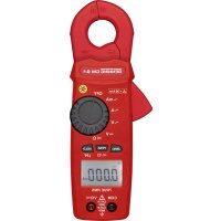
4. Unit description
See figure 1: Appliance front face
The display and operating elements shown in fig. 1 are as follows:
Measurement prongs, for inserting and gripping the single conductor containing current
NCV sensor, detector of the voltage indicator,
Prong guard, protects user from accidental contact with conductor
Opening lever, for opening and closing the current prongs
H/ INRUSH key (blue), storage of the displayed measured value (HOLD), inrush current measurements (A AC)
/ LPF key, enables the low-pass filter (LPF), null balance key (ZERO, A DC) for null balance or differential measurement (BENNING CM P2),
NCV key, voltage indicator for determining the AC voltage to earth,
A key, for measuring the AC current (BENNING CM P1) and the AC/ DC current (BENNING CM P2),
ON/OFF key, for switching the current clamp on/off, enables the digital display illumination,
Digital display, for displaying the measured value and range exceedance
Battery compartment cover, at the rear of the housing
5. General information
5.1 General information on digital current clamp meter
5.1.1 The digital display 10 is designed as a 4 digit liquid-crystal indicator with 10mm digit height and decimal point. The highest value displayed is 4200.
5.1.2 The polarity indication on the digital display ⑩ works automatically. Only a polarity contrary to the technical current direction is indicated with “-” (see arrow on the measuring clamp).
5.1.3 In case of a range exceedance (overflow), "0L." is displayed.
Attention: no display or warning by complete overload.
5.1.4 The BENNING CM P1/P2 is switched on or off by pressing the ON/OFF key 9 To switch it off, press and hold the key 9 for approx. 2 seconds. If the BENNING CM P1/ P2 is switched on, the display illumination can be enabled by pressing the key 9. It is switched off by pressing the key again or automatically after approx. 10 seconds.
5.1.5 The selection of the measuring range is automatic.
5.1.6 The H/INRUSH key (blue) has two functions:
Pressing the H/INRUSH key 5 stores the measuring result. The "HOLD" symbol simultaneously appears on the display 10. Press the key 5 again to switch the device back to measuring mode.
In measuring mode "A AC", press the H/INRUSH key 5 for approx. 2 seconds to enable the inrush current measurement. At the same time, the digital display 10 shows the "INRUSH" symbol. Here, the measuring process is initiated for 100 milliseconds after a current (>5~A) is applied. The averaged value of this time period is displayed. Press the key 5 for approx. 2 seconds again to switch the device back to normal measuring mode.
5.1.7 The LPF key has two functions:
Pressing the /LPF^6 enables the low-pass filter with a limiting frequency of approx. 160~Hz . At the same time, the digital display 10 shows the "LPF" symbol. Press the key 6 again to switch the device back to the normal mode.
In measuring mode "A DC" (BENNING CM P2), press the /LPF key 6 for approx. 2 seconds to carry out a null balance. It can also be used for differential measurement (null balance is possible for any value!). This is shown by means of the symbol on the digital display 10. Press the key 6 again to switch the device back to the normal mode.
5.1.8 NCV key 7:
Pressing the NCV key ⑦ enables the voltage indicator function (localization of AC voltages to earth). At the same time, the digital display ⑩ shows the “√ and “EF” symbols (see 8.3). Press the A~key ⑧ to switch the device back to the current measuring range.
5.1.9 Akey 3
Press the A3 to select the current measuring range. With the BENNING CM P2, you can toggle between the current types "DC" and "AC" by pressing the key again.
5.1.10 The measuring rate of the BENNING CM P1/ P2 amounts nominally to 2 measurements per second for the digital display.
5.1.11 The BENNING CM P1/ P2 switches off automatically after approx. 15 minutes (APO, Auto-Power-Off is activated, if the symbol is shown on the display 10). The automatic switch-off can be disabled by pressing the H/INRUSH key 5 and by switching on the BENNING CM P1/P2 via the ON/OFF key 5. The symbol disappears from the display 10.
5.1.12 The BENNING CM P1/ P2 is supplied by two 1.5 V batteries (IEC LR03/ AAA/ micro).
5.1.13 If the battery voltage drops below the specified operating voltage of the BENNING CM P1/ P2, then a battery symbol appears in the display 10.
5.1.14 The battery life depends on the measuring function used and is approx. 200 hours for the BENNING CM P1 and approx. 30 hours for the BENNING CM P2 without using the
background lighting.
5.1.15 Temperature coefficient of the measured value: 0.1 × (stated measuring accuracy)/ ^ C < 18^ C or >28^ C , related to the value for the reference temperature of 23^ C
5.1.16 Dimensions of unit (length x width x height) = 149 x 59 x 27,5 mm.
Weight of unit: 140g (incl. batteries)
5.1.17 Widest prong opening: 23mm
6. Ambient conditions
- The BENNING CM P1/ P2 is intended for making measurements in dry environment.
Maximum barometric elevation for making measurements: 2000m - Overvoltage category: IEC 60664/ IEC 61010 600 V category III
- Contamination class: 2 (EN 61010-1),
Protection class: IP 30 (DIN VDE 0470-1, IEC/ EN 60529)
IP 30 means: Protection against access to dangerous parts and protection against solid impurities of a diameter >2.5 mm , (3 - first index). No protection against water, (0 - second index).
- Operating temperature and relative humidity:
For operating temperatures from 0^ to 40^ : relative air humidity lower than 80% , non-condensing - Storage temperature: The BENNING CM P1/ P2 can be stored at temperatures between
- 10^ and +60^ , at a relative air humidity lower than 70% without batteries.
7. Electrical specifications
Note: The measuring precision is specified as the sum of
- a relative fraction of the measured value and
- a number of digits (counting steps of the least significant digit).
This specified measuring precision is valid for temperatures in the range from 23^ ± 5^ and relative humidity less than 80% .
7.1 AC current range
The measured value is obtained and displayed as real r.m.s. value (True RMS, AC coupling). Its calibration is adapted to sinusoidal curves. In case of deviations from this curve shape, the accuracy of the displayed value decreases.
Crest factor < 1.6 up to 100% of each final measuring range value
Crest factor < 3.2 up to 50 % of each final measuring range value
Low-pass filter deactivated:
| Measuring range Resolution | Measurement accuracy (50 Hz - 60 Hz) | Measurement accuracy (45 Hz - 400 Hz) | Overload protection | |
| 40.00 A | 0.01 A | ± (2.0 % of reading + 5 digits) | ± (3.8 % of reading + 8 digits) | 420 A eff. |
| 40.1 A - 400 A | 0.1 A | ± (2.0 % of reading + 5 digits) | ± (3.8 % of reading + 8 digits) | 420 A eff. |
Low-pass filter activated:
| Measuring range | Resolution | Measurement accuracy (50 Hz - 60 Hz) | Overload protection |
| 40.00 A | 0.01 A | ± (3.5 % of reading + 8 digits) | 420 A eff. |
| 40.1 A - 400 A | 0.1 A | ± (3.5 % of reading + 8 digits) | 420 A eff. |
Limiting frequency (-3 dB): 160 Hz
Inrush current:
Measuring range Resolution Measurement accuracy (50 Hz - 60 Hz) Overload protection
5.0 A - 400 A 0.1 A ± (3.5 % of reading + 8 digits) 420 A eff.
Integration time: 100 ms
Threshold value of the trigger current: 5 A
7.2 DC current range (BENNING CM P2)
Measuring range Resolution Measurement accuracy Overload protection
40.00 A 0.01 A ± (2.0 % of reading + 5 digits) 420 A eff.
40.1 A - 400 A 0.1 A ± (2.0 % of reading + 5 digits) 420 A eff.
8. Measuring with the BENNING CM P1/ P2
8.1 Preparing the measurement
Operate and store the BENNING CM P1/ P2 at the specified storage and operating temperatures only! Do not permanently expose the device to sunlight.
- Strong sources of interference in the vicinity of the BENNING CM P1/ P2 might involve unstable readings and measuring errors.
8.2 Current measurement

Do not exceed the maximum permitted voltage with respect to earth potential! Electrical danger!

For direct current (DC) measurements (BENNING CM P2), observe correct polarity! The arrow on the measuring clamp indicates the technical current direction. + -
After switching it on, the BENNING CM P1/P2 is automatically in function A. Otherwise, press the A~ key 8.
- For the BENNING CM P2, press the A~key ⑧ to select the desired function A~ or A~. In the A~function, press the null balance key /LPF ⑥ to switch the BENNING CM P2 to the initial mode.
- Operate opening lever 4, clamp 1 single wire live conductor centrally by means of the BENNING CM P1/ P2 current probe.
- Read off the digital display unit 10.
See figure 2: Current measurement
8.3 Voltage indicator (NCV)

The voltage indicator function is not intended for testing the absence of voltage. Even without an indication or acoustic signal, a dangerous contact voltage might be applied. Electrical danger!
The voltage indicator function is intended for non-contact detection of an alternating field. The detector 2 is located on the measuring clamp within the NCV marking. Switch the BENNING CM P1/P2 on and select the voltage indicator function by pressing the NCV key 7 . The digital display 10 shows the "V" and "EF" symbols. If a phase voltage is localized, an acoustic signal will be emitted and the intensity of the alternating field will be indicated on the digital display 10 by a maximum of 4 bars "- - - -". An indication is made in earthed AC current networks only!
Practical hint:
Interruptions (cable breaks) in cables lying around openly such as e.g. cable reels, fairy lights etc. can be traced from the feeding point (phase) to the point of interruption.
Functional range: ≥ 230V
See figure 3: Voltage indicator with buzzer
9. Maintenance

Before opening the BENNING CM P1/ P2, make sure that it is free of voltage! Electrical danger!
9.1 Securing the instrument
Under certain circumstances safe operation of the BENNING CM P1/ P2 is no longer ensured, for example in the case of:
Visible damage of the casing.
- Incorrect measurement results.
- Recognisable consequences of prolonged storage under improper conditions.
- Recognisable consequences of extraordinary transportation stress.
In such cases the BENNING CM P1/ P2 must be switched off immediately, disconnected from the measuring points and secured to prevent further utilisation.
9.2 Cleaning
Clean the casing externally with a clean dry cloth (exception: special cleaning wipers). Avoid using solvents and/ or scouring agents for cleaning the instrument. It is important to make sure that the battery compartment and battery contacts are not contaminated by leaking electrolyte. If electrolyte contamination or white deposits are present in the region of the batteries or battery casing, clean them too with a dry cloth.
9.3 Battery replacement

Before opening the BENNING CM P1/ P2, make sure that it is free of voltage! Electrical danger!
The BENNING CM P1/ P2 is supplied by means of two 1.5 V batteries of type AAA (IEC LR03).
Battery replacement is required, if the battery symbol appears on the display 10. When the BENNING CM P1/P2 is switched on, a battery test is performed.
Proceed as follows to replace the batteries:
- Switch the BENNING CM P1/P2 off.
- Lay the BENNING CM P1/ P2 face down and release the screws of the battery compartment cover.
- Lift the battery compartment lid (in the housing recess area) from the bottom section.
- Remove the discharged batteries from the battery compartment.
- Insert the new batteries into the battery compartment observing correct polarity.
- Place the battery compartment cover onto the bottom part and tighten the screw.
See figure 4: Battery replacement

Make your contribution to environmental protection! Do not dispose of discharged batteries in the household garbage. Instead, take them to a collecting point for discharged batteries and special waste material. Please inform yourself in your community.
9.4 Calibration
Benning guarantees compliance with the technical and accuracy specifications stated in the operating manual for the first 12 months after the delivery date. To maintain accuracy of the measuring results, the device must be recalibrated in regular intervals by our factory service. We recommend recalibrating the device once a year. For this purpose, send the device to the following address:
10. Environmental note

At the end of product life, dispose of the unserviceable device via appropriate collecting facilities provided in your community.