CM 7 - Multimeter BENNING - Free user manual and instructions
Find the device manual for free CM 7 BENNING in PDF.

User questions about CM 7 BENNING
0 question about this device. Answer the ones you know or ask your own.
Ask a new question about this device
Download the instructions for your Multimeter in PDF format for free! Find your manual CM 7 - BENNING and take your electronic device back in hand. On this page are published all the documents necessary for the use of your device. CM 7 by BENNING.
USER MANUAL CM 7 BENNING
Fig. 2: Direct voltage measurement
Fig. 2: Mesure de tension continue
Fig. 3: Alternating voltage measurement
Fig. 3: Mesure de tension alternative
Fig. 4: Direct/ alternating current measurement
Fig. 4: Mesure de courant continue/ alternative
Fig. 5: Resistance measurement
Fig. 6: Frequency measurement
natural_image
Technical line drawing of a handheld electronic device with internal components and mounting bracket (no text or symbols)Fig. 7: Battery replacement
Fig. 7: Remplacement de la pile
Digital current probe multimeter for
- Direct voltage measurements
- Alternating voltage measurements
- Direct current measurement
- Alternating current measurement
- Resistance measurements
- Continuity testing
- Frequency measurement
Table of contents
- User notes
- Safety note
- Scope of delivery
- Unit description
- General information
- Environment conditions:
- Electrical specifications
- Making measurements with the BENNING CM 7
- Maintenance
- Technical data of the measuring accessories
11.Environmentalnotice
1. User notes
These operating instructions are intended for
- skilled electricians and
- trained electronics personnel.
The BENNING CM 7 is intended for making measurements in dry environment. It must not be used in power circuits with a nominal voltage higher than 1000 V DC and 750 V AC (More details in Section 6. "Environmental conditions")
The following symbols are used in these operating instructions and on the BENNINGCM7:

Application around and removal from HAZARDOUS LIVE conductors is permitted.

Warning of electrical danger!
Indicates instructions which must be followed to avoid danger to persons.

Important, comply with the documentation!
The symbol indicates that the information provided in the operating instructions must be complied with in order to avoid risks.

This symbol on the BENNING CM 7 means that the BENNING CM 7 is totally insulated (protection class II).

This symbol appears in the display to indicate a discharged battery.

This symbol designates the „continuity test“ range.
The buzzer is used for the acoustic result output.

(DC) Direct voltage or current.

(AC) Alternating voltage or current.

Ground (Voltage against ground).
Note
After unmark the adhesive label „Warnung...“ (on battery compartment lid) the English text appears.
2. Safety note
The instrument is built and tested in accordance with
DIN VDE 0411 part 1/ EN 61010-1
and has left the factory in perfectly safe technical state.
To maintain this state and ensure safe operation of the appliance tester, the user must observe the notes and warnings given in these instructions at all times.

The unit may be used only in power circuits within the over-voltage category III with a conductor for 1000 V max. to earth, or within overvoltage category IV with a conductor for 600 V against ground.
Only use suitable measuring leads for this. With measurements within measurement category III or measurement category IV, the projecting conductive part of a contact tip of the measuring leads must not be longer than 4 mm.
Prior to carrying out measurements within measurement category III and measurement category IV, the push-on caps provided with the set and marked with CAT III and CAT IV must be pushed onto the contact tips. The purpose of this measure is user protection.
Remember that work on electrical components of all kinds is dangerous. Even low voltages of 30 V AC and 60 V DC may be dangerous to human life.

Before starting the appliance tester up, always check it as well as all cables and wires for signs of damage.
Should it appear that safe operation of the appliance tester is no longer possible, it should be shut down immediately and secured to prevent it being switched on accidentally.
It may be assumed that safe operation is no longer possible:
- if the instrument or the measuring cables show visible signs of damage, or
- if the appliance tester no longer functions, or
- after long periods of storage under unfavourable conditions, or
- after being subjected to rough transport.

In order to avoid danger,
- do not touch the bare prod tips of the measuring cables measuring probes,
- insert the measurement lines in the appropriately designated measuring sockets on the multimeter
3. Scope of delivery
The scope of delivery for the BENNING CM 7 comprises:
3.1 One BENNING CM 7,
3.2 One safety measuring cable, red (L = 1.4 m)
3.3 One safety measuring cable, black (L = 1.4 m)
3.4 One compact protective pouch,
3.5 One 9 V block battery
3.6 One operating instructions manual
Parts subject to wear:
- The BENNING CM 7 is fed by a 9 V block battery.
- The above-mentioned safety measuring cables (tested accessories) correspond to CAT III 1000 V and are approved for a current of 10 A.
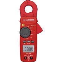
4. Description of appliance tester
See figure 1: Appliance front face
The display and operator control elements specified in Fig. 1 are designated as follows:
① Digital display, for the measurement value, bar graph display, overranging display,
② Polarity indication,
③ Battery status indication, appears when the battery is discharged,
④ Button (yellow), display lighting,
⑤ ZERO key, for zero balance or differential measuring
6 MIN/MAX button, storage of the highest and lowest measured values,
⑦ Button PEAK, peak value storage,
8 Rotary switch, for selecting the measurement function,
9 Jack (positive ^1 ), for V, Ω
⑩ COM jack, common socket for voltage, resistance measurement and continuity testing,
⑪ Opening lever, for opening and closing the current probe.
⑫ Bulge of current probe, protects against contact with conductor.
⑬ Measuring pliers, for clamping on the single wire current-carrying conductor.
14 HOLD button, storage of the indicated measured value,
1) This is what the automatic polarity indication for DC voltage refers to
5. General information
5.1 General details on the current probe multimeter
5.1.1 The digital display ① is a 3 34 -digit liquid crystal display with 14 mm high numerals, complete with decimal point. The largest numerical value which can be displayed is 4000.
5.1.2 The polarity indication ② is automatic. Only one polarity with respect to the socket marked “-” is indicated.
5.1.3 The overranging is indicated by "0L" or "-0L" and, in part, an acoustic warning.
Warning, no indication and prior warning in the event of an overload condition!
5.1.4 Button (yellow) ④ switches on the display illumination. Shutdown is effected by a renewed press of the button or automatically after 60 seconds.
5.1.5 ZERO key ⑤ (zero balance key)
Press the key to perform a zero balance for direct current (DC) measurements. This can be used as well for differential measuring in the resistance or frequency range. Indication by “REL” on the digital display. Press the key again to indicate the stored difference (Offset). The indication “REL” on the digital display is flashing. Press and hold the key (approx. 2 seconds) to switch back to the measuring mode.
5.1.6 Measured value storage "HOLD": Press the button "HOLD" 14 to store the measured result. At the same time, the display shows the symbol "HOLD". A renewed press of the button switches back into measuring mode.
5.1.7 The MIN/ MAX button function 6 inputs and stores automatically the highest and lowest measured value. The following values are indicated by button operation:
“MAX” indicates the stored maximum value, and “MIN” indicates the lowest value. The continuous detection of the MAX-/ MIN value can be stopped or started by pressing the button “HOLD” 14. Pressing the button “MIN/MAX” for an extended period of time (2 seconds) switches back into normal mode.
5.1.8 The button PEAK ⑦ (peak value storage) detects and stores the positive and negative peak/ crest value in the function V AC and A AC. At the start of the measurement, press the button PEAK ⑦ for approx. 3 seconds in order to increase measurement precision and to fine-adjust the BENNING CM 7. Pressing the button indicates the "PMAX" or "PMIN" values in the display. An extended operation (2 seconds) of the button PEAK ⑦ switches back into a standard mode.
5.1.9 The measuring rate of the BENNING CM 7 amounts nominally to 1.5 measurements per second for the digital display.
5.1.10 The BENNING CM 7 is switched on and off with the rotary switch ⑧. Shutdown position "OFF".
5.1.11 The BENNING CM 7 switches off automatically after approx. 30 minutes (APO, Auto-Power-Off). It switches back on again if a button or the rotary switch is operated. A buzzer tone signals automatic switchoff of the appliance. The automatic switchoff can be deactivated by pressing a button (except the button "HOLD") and simultaneously switching on the BENNING CM 7 from switch position "OFF".
5.1.12 Temperature coefficient of the measured value: 0.2 x (stated measuring precision)/°C < 18 °C or > 28 °C, related to the value for the reference temperature of 23 °C.
5.1.13 The BENNING CM 7s supplied by a fitted 9 V block battery (IEC 6 LR 61).
5.1.14 If the battery voltage drops below the specified operating voltage of the BENNING CM 7, then a battery symbol appears in the display.
5.1.15 The life span of a battery amounts to approx. 100 hours (alkali battery).
5.1.16 Appliance dimensions:
(L x W x H) = 275 x 105 x 51 mm Appliance weight: 534 g
5.1.17 The safety measuring cables supplied are expressly suited for the rated voltage and the rated current of the BENNING CM 7.
5.1.18 Largest opening of pliers: 53 mm
5.1.19 Largest cable diameter: 51 mm
6. Environment conditions:
- The BENNING CM 7 is intended for making measurements in dry environment.
- Maximum barometric elevation for making measurements: 2000 m,
- Overvoltage category/ Siting category: IEC 60664-1/ IEC 61010-1 → 600 V category IV, 1000 V category III
- Contamination class: 2,
- Protection Class: IP 30 (DIN VDE 0470-1 IEC/ EN 60529)
IP 30 means: Protection against access to dangerous parts and protection against solid impurities of a diameter > 2.5 mm, (3 - first index). No protection against water, (0 - second index).
- Operating temperature and relative humidity:
For operating temperature from 0 °C to 30 °C: relative humidity less than 80 % For operating temperatures from 31 °C to 40 °C: relative humidity less than 75 % For operating temperature from 41 °C to 50 °C: relative humidity less than 45 %
- Storage temperature: The BENNING CM 7 can be stored at any temperature in the range from -20 °C to +60 °C (relative humidity from 0 to 80 %). The battery should be taken out of the instrument for storage.
7. Electrical specifications
Note: The measuring precision is specified as the sum of
- a relative fraction of the measured value and
- a number of digits (counting steps of the least significant digit).
This specified measuring precision is valid for temperatures in the range from 18 °C to 28 °C and relative humidity less than 80 %.
7.1 Direct voltage ranges
The input resistance amounts to 1 MΩ
| Meas. range | Resolution | Meas. precision | Overload protection |
| 400 V | 0,1 V | ± (0.7 % of the measuring value + 2 digits) | 750 V_eff |
| 1000 V | 1 V | ± (0.7 % of the measuring value + 2 digits) | 750 V_eff |
7.2 Alternating voltage ranges
The input resistance amounts to 1 MΩ in parallel 100 pF.
| Measuring range | Resolution | Meas. precision *1*2 within the frequency range 50 Hz - 500 Hz | Overload protection |
| 400 V | 0,1 V | ± (1 % of the measuring value + 5 digits) | 750 V_eff |
| 750 V | 1 V | ± (1 % of the measuring value + 5 digits) | 750 V_eff |
*1 The measuring value is gained and indicated as effective value (True RMS, AC coupling). The measuring accuracy is specified for sinusoidal curves and applies to the final value of the measuring range as well as for non-sinusoidal curves up to 50 % of the final value of the measuring range.
In case of non-sinusoidal curves, the indicating value becomes inaccurate. Thus, an additional error occurs for the following crest factors:
crest factor from 1.4 to 2.0 additional error + 1 % crest factor from 2.0 to 2.5 additional error + 2.5 % crest factor from 2.5 to 3.0 additional error + 4 %
*2 additionally ± 4 digits for measuring values < 15 % of the final value of the measuring range
7.3 Direct current (DC) ranges
| Meas. range | Resolution | Measuring accuracy | Overload protection |
| 0 - 200 A | 0,1 A | ± (2,9 % of the measuring value + 3 A) | 1000 A_eff |
| 200 - 400 A | 0,1 A | ± (1,9 % of the measuring value + 2 A) | 1000 A_eff |
| 400 - 1000 A | 1 A | ± (2,9 % of the measuring value + 5 A) | 1000 A_eff |
The indicated accuracy is specified for conductors which are gripped by means of the measuring clamp 13 in the middle (see Fig. 4 Direct/ alternating current measurement). For conductors which are not gripped in the middle, an additional error of 1 % of the indicating value has to be considered.
Error according to remanence: 1 % (repeating measurement)
7.4 Alternating current ranges
| Measuring range | Resolution | Meas. precision *1*2 within the frequency range 50 Hz - 400 Hz | Overload protection |
| 0 - 200 A | 0,1 A | ± (2.9 % of the measuring value + 3 A) | 1000 A_eff |
200 - 400 A 0,1 A ± (1.9 % of the measuring value + 2 A) 1000 A
within the frequency
range 50 Hz - 200 Hz
400 - 1000 A 1 A ± (2.9 % of the measuring value + 5 A) 1000 A
eff
*1 The measuring value is gained and indicated as effective value (True RMS, AC coupling). The measuring accuracy is specified for sinusoidal curves and applies to the final value of the measuring range as well as for non-sinusoidal curves up to 50 % of the final value of the measuring range.
In case of non-sinusoidal curves, the indicating value becomes inaccurate.
Thus, an additional error occurs for the following crest factors:
crest factor from 1.4 to 2.0 additional error + 1 %
crest factor from 2.0 to 2.5 additional error + 2.5 %
crest factor from 2.5 to 3.0 additional error + 4 %
*2 additionally ± 4 digits for measuring values < 15 % of the final value of the measuring range
The stated precision is specified for conductors that are centrally clamped by the current probe 13 (see Fig. 4 Direct/ alternating current measurement). For conductors that are not centrally clamped, an additional error of 1 % of the display value needs to be taken into account.
7.5 Resistance measuring range and acoustic continuity testing
Overload protection: 600 V _eff
Meas. range Resolution Meas. precision Max. idling voltage
| 400 Ω | 0,1 Ω | ± (1 % of the measuring value + 3 digits) | 3 V |
The built-in buzzer sounds in the case of a resistance R less than 30 Ω.
7.6 Frequency ranges
Overload protection: 1000 A _eff
| Meas. range | Resolution | Meas. precision |
| 400 Hz | 1 Hz | ± (1 % of the measuring value + 2 digits) |
Minimum input frequency: 20 Hz
Minimum input sensitivity: 3 A _eff
7.7 PEAK HOLD
Measuring ranges: V AC, A AC
In the PEAK-HOLD function (storage of the peak value), an additional error has to be considered for the specified accuracy:
+ (± 3 % + 20 digits)
Measuring values > 750 Vpeak or 800 Apeak are not specified.
The PEAK-HOLD function automatically selects the measuring range with the lowest resolution.
7.8 MIN/MAX
In the MIN/MAX function (storage of the minimum/ maximum value), an additional error has to be considered for the specified accuracy:
+ (± 15 digits)
The MIN/MAX function automatically selects the measuring range with the lowest resolution.
8. Making measurements with the BENNING CM 7
8.1 Preparations for making measurements
Operate and store the BENNING CM 7 only at the specified storage and operating temperatures conditions. Avoid continuous insulation.
- Check rated voltage and rated current details specified on the safety measuring lines. The nominal voltage and current ratings of the safety measuring cables included in the scope of delivery correspond to the ratings of the BENNING CM 7.
- Check the insulation of the safety measuring cables. Discard the safety measuring cables immediately if the insulation is damaged.
- Check safety measuring lines for continuity. If the conductor in the safety measuring line is interrupted, the safety measuring line must be quarantined immediately.
- Before - at the rotary switch ⑧ a different function is selected, the safety measuring lines must be disconnected from the measuring point.
- Strong sources of interference in the vicinity of the BENNING CM 7 can lead to unstable readings and measuring errors.
8.2 Voltage measuring

Do not exceed the maximum permitted voltage with respect to earth potential! Electrical danger!
The highest voltage which may be applied to the jacks,
- COM socket 10
- jack for V, Ω ⑨
of the BENNING CM 7 against ground, amounts to 1000 V.
- Use the rotary switch ⑧ to select the required function (V AC) or (V DC) on the BENNING CM 7.
- The black safety measuring cable has to be contacted with the COM jack 10 on the BENNING CM 7.
- The red safety measuring cable has to be connected to the jack for V, Ω 9 on the BENNING CM 7.
- Bring the safety measuring lines into contact with the measuring points, read off measured value on the digital display ① on the BENNING CM 7.
See figure 2: Direct voltage measurement
See figure 3: Alternating voltage measurement
8.3 Direct/ alternating current measurement
8.3.1 Preparations for making measurements
Operate and store the BENNING CM 7 only at the specified storage and operating temperatures conditions. Avoid continuous insulation.
Strong sources of interference in the vicinity of the BENNING CM 7 can lead to unstable readings and measuring errors.

Do not apply any voltage to the output contacts of the BENNING CM 7! Any possibly connected safety measuring cables have to be removed.
8.3.2 Direct/ alternating current measurement
- Use the rotary switch ⑧ to select the required function (AAC) or (ADC) on the BENNING CM 7.
- Operate opening lever ⑪, clamp single wire live conductor centrally by means of the BENNING CM 7 current probe.
- Read off the digital display unit ①.
See figure 4: Direct/ alternating current measurement
8.4 Resistance measuring and acoustic continuity testing
- Use the rotary switch ⑧ to select the required function (Ω) on the BENNING CM 7.
- The black safety measuring cable has to be contacted with the COM jack 10 on the BENNING CM 7.
The red safety measuring cable has to be connected to the jack for V, Ω 9 on the BENNING CM 7. - Bring the safety measuring lines into contact with the measuring points, read off measured value on the digital display ① on the BENNING CM 7.
- If the conductor resistance between the COM jack ⑩ and the jack for V, Ω ⑨ 30 Ω, the fitted buzzer sounds on the BENNING CM 7.
See figure 5: Resistance measurements
8.5 Frequency measurement via current measuring pliers

Do not apply any voltage to the output contacts of the BENNING CM 7! Any possibly connected safety measuring cables have to be removed.
- Use the rotary switch ⑧ to select the required function (Hz) on the BENNING CM 7.
- Operate opening lever ⑪, clamp single wire live conductor centrally by means of the BENNING CM 7 current probe.
- Read off the digital display unit ①.
See figure 6: Frequency measurement via current measuring pliers
9. Maintenance

Before opening the BENNING CM 7, make quite sure that it is voltage free! Electrical danger!
Work on the opened BENNING CM 7 under voltage may be carried out only by skilled electricians with special precautions for the prevention of accidents.
Make the BENNING CM 7 voltage free as follows before opening the instrument;
- First remove the two safety measuring lines from the object to be measured.
- Then disconnect the two safety measuring cables from the BENNINGCM7.
- Turn the rotary switch ⑧ to the switch setting "OFF".
9.1 Securing the instrument
Under certain circumstances safe operation of the BENNING CM 7 is no longer ensured, for example in the case of:
- Visible damage of the casing.
- Incorrect measurement results.
- Recognisable consequences of prolonged storage under improper conditions.
- Recognisable consequences of extraordinary transportation stress.
In such cases the BENNING CM 7 must be switched off immediately, disconnected from the measuring points and secured to prevent further utilisation.
9.2 Cleaning
Clean the casing externally with a clean dry cloth (exception: special cleaning wipers). Avoid using solvents and/or scouring agents for cleaning the instrument. It is important to make sure that the battery compartment and battery contacts are not contaminated by leaking electrolyte.
If electrolyte contamination or white deposits are present in the region of the batteries or battery casing, clean them too with a dry cloth.
9.3 Battery change

Before opening the BENNING CM 7, make quite sure that it is voltage free! Electrical danger!
The BENNING CM 7 is fed by a 9 V block battery.
A battery change (see Figure 7) is required, if the battery symbol ③ appears in the display ①.
Proceed as follows to replace the batteries:
- Disconnect the safety measuring cables from the measuring circuit.
- Disconnect the safety measuring cables from the BENNING CM 7.
- Set the rotary switch ⑧ to the switch setting "OFF".
- Lay the BENNING CM 7 face down and release the screws of the battery compartment cover.
- Lift the battery compartment lid (in the housing recess area) from the bottom section.
- Lift the discharged battery from the battery compartment and disconnect the battery supply lines from the battery.
- The new battery has to be connected to the battery supply lines, and arrange these such that they are not crushed between the housing parts. Then place the battery into the battery compartment provided for this purpose.
- Place the battery compartment cover onto the bottom part and tighten the screw.
See figure 7: Battery replacement

Make your contribution to environmental protection! Do not dispose of discharged batteries in the household garbage. Instead, take them to a collecting point for discharged batteries and special waste material. Please inform yourself in your community.
9.4 Calibration
To maintain the specified precision of the measurement results, the instrument must be recalibrated at regular intervals by our factory service. We recommend a recalibration interval of one year. Send the appliance to the following address:
10. Technical data of the measuring accessories
- Standard: EN 61010-031,
- Maximum rated voltage to earth ( 12 ) and measuring category:
With push-on caps: 1000 V CAT III, 600 V CAT IV,
Without push-on caps: 1000 V CAT II,
- Maximum rated current: 10 A,
- Protective class II (回), continuous double or reinforced insulation,
- Contamination class: 2,
- Length: 1.4 m, AWG 18,
-Environmentalconditions:
Maximum barometric elevation for making measurements: 2000 m,
Temperatures: 0 °C to + 50 °C, humidity 50 % to 80 %
- Only use the test leads if in perfect and clean condition as well as according to this manual, since the protection provided could otherwise be impaired.
- Throw the test leads out if the insulation is damaged or if there is a break in the cable/ plug.
- Do not touch the bare contact tips of the test leads. Only grab the area appropriate for hands!
- Insert the angled terminals in the testing or measuring device.
11.Environmentalnotice

At the end of the product's useful life, please dispose of it at appropriate collection points provided in your country.
Campi misure: V CA, A CA