CM 91 - Multimeter BENNING - Free user manual and instructions
Find the device manual for free CM 91 BENNING in PDF.

| Product type | Digital leakage current clamp meter |
| Brand | BENNING |
| Model | CM 91 (CM 9-1) |
| Dimensions (L × W × H) | 210 × 76 × 33.5 mm |
| Weight (with batteries) | 296 g |
| Power supply | 2 batteries 1.5 V type R3 (AAA/LR03) |
| Battery life | Approximately 40 to 60 hours (without backlight or continuity test) |
| Display | LCD, 4 digits, 6000 counts, with decimal point and polarity indicator |
| Measurement rate | 2 measurements per second |
| Overvoltage category | CAT III 600 V / CAT IV 300 V |
| Maximum jaw opening | 23 mm |
| Measurement functions | AC/DC voltage, AC current (True RMS), resistance, continuity test, leakage current |
| DC voltage ranges | 60.00 V / 600.0 V (accuracy ±1.0% + 4 digits) |
| AC voltage ranges | 60.00 V / 600.0 V (accuracy ±1.2% + 5 digits) |
| AC current ranges | 6.000 mA / 60.00 mA / 600.0 mA / 6.000 A / 60.00 A |
| Resistance ranges | 600.0 Ω / 6.000 kΩ / 60.00 kΩ / 600.0 kΩ (accuracy ±1.0% + 4 digits) |
| Continuity test | Audible signal for resistance < 45 Ω |
| Low-pass filter (LPF) | 40 Hz to 70 Hz, activatable in current mode |
| Special functions | Peak value (PEAK), hold (HOLD), manual range selection, zero (ZERO), backlight |
| Auto power off | After 30 minutes (deactivatable) |
| Protection | Double insulation (class II), IP30 |
| Operating temperature | 0 °C to +40 °C, humidity < 80% |
| Included accessories | Red/black test leads, protective holster, batteries, instruction manual |
| Maintenance and cleaning | Clean with a dry cloth; do not use solvents |
| Repairability | Contains no user-serviceable parts; repair by qualified personnel |
Frequently Asked Questions - CM 91 BENNING
User questions about CM 91 BENNING
0 question about this device. Answer the ones you know or ask your own.
Ask a new question about this device
Download the instructions for your Multimeter in PDF format for free! Find your manual CM 91 - BENNING and take your electronic device back in hand. On this page are published all the documents necessary for the use of your device. CM 91 by BENNING.
USER MANUAL CM 91 BENNING
TRUE RMS leakage current clamp according to EN 61557-13 for
- measuring the leakage currents (differential current and protective conductor current) in electrical systems and devices
- AC/ DC voltage measurements
- AC current measurements
- resistance measurements
- continuity tests
Table of contents
- User instructions
- Safety instructions
- Scope of delivery
- Device description
- General information
- Ambient conditions
- Electrical specifications
- Measuring with the BENNING CM 9-1
- Maintenance
- Technical data of measuring accessories
-
Environmental note
-
User instructions
This operating manual is intended for
-
skilled electricians and
-
electrotechnically trained personnel.
The BENNING CM 9-1 is intended for making measurements in dry environment. It must not be used in power circuits with a nominal voltage higher than CAT IV 300V or CAT III 600V (More details in Section 6. "Ambient conditions").
The following symbols are used in this operating manual and on the BENNING CM 9-1:

Application around and removal from HAZARDOUS LIVE conductors is permitted.

Warning of electrical danger!
Indicates instructions which must be followed to avoid danger to persons.

Attention! Must comply with documentation!
This symbol indicates that the information provided in the operating manual must be complied with in order to avoid risks.
CAT III
Measuring category III is applicable to testing and measuring circuits connected to the distribution circuit of the low-voltage mains installation of a building.
Measuring category IV is applicable to testing and measuring circuits connected to the feed-in point of the low-voltage mains installation of a building.

Do not use the device in external low-frequency magnetic fields with more than 30A / m

This symbol on the BENNING CM 9-1 indicates that the BENNING CM 9-1 is equipped with protective insulation (protection class II).

Please observe the operating manual!

This symbol appears on the display to indicate a discharged battery.

This symbol designates the "continuity test" field. The buzzer tended for acoustic result output.

(DC) Direct voltage

(AC) Alternating voltage or current

Ground (voltage against ground)
2. Safety instructions
The instrument is built and tested in accordance with
DIN VDE 0411 Part 1/ EN 61010-1
DIN VDE 0411 Part 2-032/EN 61010-2-032
DIN VDE 0411 Part 2-033/EN 61010-2-033
DIN VDE 0411 Part 031/EN 61010-031
DIN VDE 0413 Part 13/EN 61557-13
and has left the factory in perfectly safe technical condition.
To preserve this condition and to ensure safe operation of the device, the user must observe the notes and warnings given in these instructions at all times. Improper handling and non-observance of the warnings might involve severe injuries or danger to life.

WARNING! Be extremely careful when working with bare conductors or main line carrier! Contact with live conductors will cause an electric shock!

The BENNING CM 9-1 must be used in electrical circuits of overvoltage category III with a conductor for a maximum of 600V to earth or of overvoltage category IV with a conductor for a maximum of 300V to earth only.
Only use suitable measuring leads for this. With measurements within measurement category III or measurement category IV, the projecting conductive part of a contact tip of the measuring leads must not be longer than 4mm
Prior to carrying out measurements within measurement category III and measurement category IV, the push-on caps provided with the set and marked with CAT III and CAT IV must be pushed onto the contact tips. The purpose of this measure is user protection.
Please observe that work on live parts and electrical components of all kinds is dangerous! Even low voltages of 30 V AC and 60 V DC may be dangerous to human life!

Before starting the current clamp multimeter, always check the device as well as all measuring leads for damages.
If it can be assumed that safe operation is no longer possible, switch the device off immediately and secure it against unintended operation.
Safe operation can be assumed to be no longer possible, if
- the device or the measuring leads exhibit visible damages,
- the device no longer works,
- the device has been stored under unfavourable conditions for a longer period of time,
- the device was exposed to extraordinary stress during transport, or
- if the device or the measuring leads are exposed to moisture.

Maintenance:
Do not open the multimeter, because it contains no components which can be repaired by the user. Repair and service must be carried out by qualified personnel only!

Cleaning:
Regularly wipe the housing by means of a dry cloth and cleaning agent. Do not use any polishing agents or solvents!
3. Scope of delivery
The scope of delivery of the BENNING CM 9-1 comprises:
3.1 One BENNING CM 9-1
3.2 One safety measuring lead, red (L = 1.4m)
3.3 One safety measuring lead, black (L = 1.4m)
3.4 One compact protective pouch
3.5 Two 1.5 V micro batteries (IEC LR03/ AAA)
3.6 One operating manual
Parts subject to wear:
- The BENNING CM 9-1 is supplied by means of two integrated 1.5V micro batteries (IEC LR 03/ AAA).
- The above mentioned safety measuring leads (tested spare part, part no.
044145) are approved in accordance with CAT III 1000 V/ CAT IV 600 V and for a current up 10A .
4. Device description
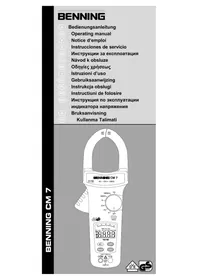
See figure 1: Appliance front face
The display and operating elements shown in figure 1 are designated as follows:
Measuring clamp, for clamping live conductors,
2 Prong guard, protects user from accidental contact with conductor
3 Key (yellow), display illumination
Opening lever, for opening and closing the current prongs
5 Rotary switch, for selecting the measurement function
ZERO/LPF key, for zero balance or differential measuring, enabling the low-pass filter (LPF)
PEAK key, peak value storage
HOLD/RANGE button, storage of the indicated measured value, switchover to manual measuring range selection (V and A).
Digital display, for displaying the measured value and range exceedance
COM jack, common jack for voltage and resistance measurements as well as for continuity testing, marked in black
V-Ω jack (positive), common jack for voltage and resistance measurements as well as for continuity testing, marked in red
Battery compartment cover, at the rear of the housing
5. General information
5.1 General information on digital current clamp multimeter
5.1.1 The digital display 9 is designed as a 4 digit liquid-crystal indicator with 12mm digit height with decimal point. The highest value displayed is 6000.
5.1.2 The polarity indication on the digital display ⑨ works automatically. Contrary to the measurement-wire definition, only one pole is indicated as “-”.
5.1.3 In case of a range exceedance (overflow), "0L." is displayed.
Attention: no display or warning by complete overload.
5.1.4 The rotary switch 5 is intended for selecting the measuring function. The selection of the measuring range is automatic.
5.1.5 The ZERO/LPF key has two functions:
- ZERO function:
For zero adjustment in current measurement. Can also be used for all ranges for differential measurement (zero setting possible for any value). Indicated by "ZERO" in the digital display 9.
- LPF function (low-pass filter):
Press the ZERO button for 2 seconds to enable a low-pass filter (40 Hz to 70 Hz) in the A and mA ranges. An active filter is visualized by the "LPF" symbol on the LC display The low-pass filter (LPF) suppresses high-frequency interfering signals generated by electrical devices/installations with frequency converters. The limiting frequency is approx. 180Hz
Note:
When the low-pass filter (LPF) is disabled, the frequency characteristics of the BENNING CM 9-1 meet the requirements of EN 61557-16 (VDE 0413-16) and can be used to measure protective conductor currents and differential currents of electrical devices.
5.1.6 The PEAK key has two functions:
- Press this key in the measuring modes V and A to measure and store the peak value. Briefly press the key again to return to the normal mode.
- In the measuring mode, press the PEAK key 7 to change from resistance measurement to the acoustic continuity test.
5.1.7 The HOLD/RANGE key has two functions:
The measuring result can be stored by pressing the HOLD key ⑧. The "HOLD" symbol simultaneously appears on the display ⑨. Press the key again to switch the device back to measuring mode. - Press and hold the key for 2 seconds to leave the automatic measuring range selection and to manually switch to the next higher measuring range (V and A). As soon as another measuring function is selected via the rotary switch , the automatic measuring range selection is active again.
5.1.8 The yellow illumination key ③ activates the illumination of the display ⑨. It is switched off by pressing the key again or automatically after approx. 30 seconds.
5.1.9 The measuring rate of the BENNING CM 9-1 amounts nominally to 2 measurements per second for the digital display.
5.1.10 The BENNING CM 9-1 is switched on and off with the rotary switch Shutdown position "OFF".
5.1.11 The BENNING CM 9-1 switches off automatically after approx. 30 minutes (APO, Auto-Power-Off is activated, if the symbol is shown on the display ). It switches on again, if the rotary switch is switched on again from switch position "OFF". Automatic switch-off can be deactivated by pressing the HOLD key and by simultaneously switching on the BENNING CM 9-1 from the switching position "OFF". The symbol disappears from the display .
5.1.12 The BENNING CM 9-1 is supplied by two 1.5 V batteries (IEC LR03/ AAA/ micro).
5.1.13 If the battery voltage drops below the specified operating voltage of the BENNING CM 9-1, then a battery symbol appears in the display 9.
5.1.14 The battery life depends on the measuring function used and is approximately 40 hours to 60 hours without using the acoustic continuity test and background lighting (alkaline battery).
5.1.15 Temperature coefficient of the measured value: 0.1 × (stated measuring accuracy)/ ^ C < 18^ C or >28^ C , related to the value for the reference temperature of 23^ C
5.1.16 Dimensions of unit (length x width x height) = 210 x 76 x 33,5 mm. Weight of unit: 296 g (incl. batteries)
5.1.17 The safety measuring leads and measurement tips supplied are especially suited to the rated voltage of the BENNING CM 9-1. The measuring tips can be protected by caps.
5.1.18 Widest prong opening: 23 mm
6. Ambient conditions
-
The BENNING CM 9-1 is intended for making measurements in dry environment.
-
Maximum barometric elevation for making measurements: 2000 m ,
-
Overvoltage category: IEC 60664/ IEC 61010 300 V category IV; 600 V category III
-
Operating class of current sensor: EN 61557-13, class 2, ≤ 30 A/m, @ In: 3.5 mA to 600 mA, fn: 40 Hz to 1 kHz
-
Contamination class: 2 (EN 61010-1),
Protection class: IP 30 (DIN VDE 0470-1, IEC/ EN 60529)
IP 30 means: Protection against access to dangerous parts and protection against solid impurities of a diameter >2.5mm (3 - first index). No protection against water, (0 - second index).
- Operating temperature and relative humidity:
For operating temperatures from 0^ to 40^ : relative air humidity lower than 80% , non-condensing.
- Storage temperature: The BENNING CM 9-1 can be stored at temperatures between - 10^ and +60^ , at a relative air humidity lower than 80% without batteries.
7. Electrical specifications
Note: The measuring precision is specified as the sum of
- a relative fraction of the measured value and
- a number of digits (counting steps of the least significant digit).
This specified measuring precision is valid for temperatures in the range from 23^ ± 5^ and relative humidity less than 80% . The stated accuracy is specified for 1% to 100% of the final measuring range value.
7.1 DC voltage ranges
The input resistance is ≥ 2M
| Measuring range | Resolution | Measurement accuracy | Overload protection |
| 60.00 V | 0.01 V | ± (1.0 % + 4 digits) | 600 V AC/DC |
| 60.0 V - 600.0 V | 0.1 V | ± (1.0 % + 4 digits) | 600 V AC/DC |
7.2 AC voltage range
The measured value is obtained and displayed as real r.m.s. value (True RMS, AC coupling). Its calibration is adapted to sinusoidal curves. In case of deviations from this curve shape, the accuracy of the displayed value decreases.
Crest factor < 2.0 up to 100% of each final measuring range value
Crest factor < 4.0 up to 50% of each final measuring range value
The input resistance is ≥ 2M
Measuring range Resolution Measurement accuracy Overload protection
60.00 V 0.01 V ± (1.2 % + 5 digits) 600 V AC/DC
60.0 V - 600.0 V 0.1 V ± (1.2 % + 5 digits) 600 V AC/DC
7.3 AC current range
The measured value is obtained and displayed as real r.m.s. value (True RMS, AC coupling). Its calibration is adapted to sinusoidal curves. In case of deviations from this curve shape, the accuracy of the displayed value decreases.
Crest factor < 2.0 up to 100% of each final measuring range value
Crest factor < 4.0 up to 50% of each final measuring range value
Overload protection: 60 A AC/DC
low-pass filter (40 Hz - 70 Hz) deactivated
Measuring range Resolution Measurement accuracy
| 15 Hz ~ 40 Hz 40 Hz ~ 70 Hz 70 Hz ~ 200 Hz | ||
| 6.000 mA*1 | 0.001 mA | ± (2.0 % + 10 digits) ± (1.0 % + 10 digits) ± (2.5 % + 10 digits) |
| 60.00 mA | 0.01 mA | |
| 600.0 mA | 0.1 mA | ± (2.0 % + 7 digits) ± (1.0 % + 7 digits) ± (2.5 % + 7 digits) |
| 6.000 A 0.001 A | ||
| 60.00 A | 0.01 A | |
^1 Lowest value displayed: 0.010 mA
Frequency characteristics according to EN 61557-16 (VDE 0413-16)
Limiting frequency fg (-3 dB): approx. 1 kHz
low-pass filter (40 Hz - 70 Hz) activated
Measuring range Resolution Measurement accuracy
| 40 Hz ~ 70 Hz | ||
| 6.000 mA*1 | 0.001 mA | ± (1.0 % + 10 digits) |
| 60.00 mA | 0.01 mA | ± (1.0 % + 7 digits) |
| 600.0 mA | 0.1 mA | |
| 6.000 A 0.001 A | ||
| 60.00 A | 0.01 A | |
^+1 Lowest value displayed: 0.010 mA
Limiting frequency fg (-3 dB): approx. 180 Hz
7.4 Resistance range
Open circuit-voltage: approx. 3 V, max. testing current 1 mA
| Measuring range | Resolution | Measurement accuracy | Overload protection |
| 600.0 Ω | 0.1 Ω | ± (1.0 % + 4 digits) | 600 V AC/DC |
| 6.000 kΩ | 1 Ω | ||
| 60.00 kΩ | 10 Ω | ||
| 600.0 kΩ | 100 Ω |
7.5 Continuity test
Open circuit-voltage: approx. 3V max. testing current 1 mA
The built-in buzzer sounds when resistance is less than 45
7.6 Variations and uncertainties
| Variation | ||
| E1 Position | 1 % of the measured value | |
| E2 Supply voltage | - | |
| E3 Temperature | 0.1 x (stated measuring accuracy)/ °C (<18 °C or >28 °C) | |
| E9 Distorted curve shape | - | |
| E10 DC components in the mains | - | |
| E11 External low-frequency magnetic field (15 Hz to 400 Hz acc. to IEC 61000-4-8) | ± 10 μA per 1 μT (magnetic field) | |
| E12 Load current when using the differential current method | ± 6 μA per 1 A load current additionally | |
| E13 Contact current caused by common-mode rejection | - | |
| E14 Frequency - | ||
| E15 Repeatability - | ||
| Intrinsic uncertainty (A) see measuring accuracy, sections 7.1 to 7.4 | ||
| Operating uncertainty (B) 10 A/ m 30 A/ m Measured value 3.5 mA < 15 % < 20 % Measured value >10 mA < 10 % < 12,5 % | ||
8. Measuring with the BENNING CM 9-1
8.1 Preparing the measurement
Operate and store the BENNING CM 9-1 at the specified storage and operating temperatures only! Do not permanently expose the device to sunlight.
- Check rated voltage and rated current details specified on the safety measuring leads. The nominal voltage and current ratings of the safety measuring leads included in the scope of delivery correspond to the ratings of the BENNING CM 9-1.
- Check the insulation of the safety measuring leads. If the insulation is damaged, the BENNING CM 9-1 must be scrapped immediately.
- Check the continuity of the safety measuring leads. If the leads are disconnected at any point, remove it immediately.
- Before at the rotary switch 5 a different function is selected, the safety measuring leads must be disconnected from the measuring point.
- Strong sources of interference in the vicinity of the BENNING CM 9-1 might involve unstable readings and measuring errors.
8.2 Voltage measurement

Do not exceed the maximum permitted voltage with respect to earth potential!
Please observe the overvoltage category of the electric circuit! Attach the protective caps (CAT III/IV) to the contact tips before making measurements in circuits of overvoltage category CAT III or IV.
Electrical danger!
The maximum voltage which may be applied to the sockets
COM socket, black 10
V-Ω socket (positive) for voltage and resistance measurements and continuity testing (marked red)
of the BENNING CM 9-1 against ground, amounts to 300V CAT IV/600 V CAT III.
- Use the rotary switch ⑤ to select the required function V= or V~ on the BENNING CM 9-1.
- The black safety measuring lead has to be contacted with the COM jack on the BENNING CM 9-1.
- Connect the red safety measuring lead to the V-Ω jack h , marked in red.
- Bring the safety measuring leads into contact with the measuring points, read off measured value on the digital display on the BENNING CM 9-1.
Note:
- In small voltage measuring ranges, the zero-volt indication does not appear (due to interference) when the safety measuring leads are open. Make sure that the BENNING CM 9-1 is fully functional by short-circuiting the measuring tips.
See figure 2: DC voltage measurement
See figure 3: AC voltage measurement
8.3 Current measurement

Do not apply any voltage to the input jacks 10 and 1 of the BENNING CM 9-1! Any possibly connected safety measuring leads have to be removed.
- Use the rotary switch ⑤ to select the required function mA~ or A~ on the BENNING CM 9-1.
- If necessary, press the ZERO key 6 for 2 seconds to enable the low-pass filter (LPF).
- Press the "ZERO" button ⑥ to set the BENNING CM 9-1 to the starting point.
- Operate opening lever 4, clamp 1 single wire live conductor centrally by means of the BENNING CM 9-1 current probe.
- Read off the digital display unit 9.
8.3.1 Leakage current measurement at the ground conductor
See figure 4: Leakage current measurement at the ground conductor
8.3.2 Differential current measurement at single-phase systems
See figure 5: Differential current measurement at single-phase systems
8.3.3 Leakage current measurement via ground conductor (charge eliminator) for three-phase supply
See figure 6: Leakage current measurement via ground conductor (charge eliminator) for three-phase supply
8.3.4 Differential current measurement, load supplied in three-phase, without N-type conductor
See figure 7: Differential current measurement, load supplied in three phase, without N-type conductor
8.3.5 Differential current measurement, load supplied in three-phase, with N-type conductor
See figure 8: Differential current measurement, load supplied in three phase, with N-type conductor
8.3.6 Alternating current measurement
See figure 9: Alternating current measurement
8.4 Resistance measurement
- Select the function by means of the rotary switch ⑤ of the BENNING CM 9-1.
- The black safety measuring lead has to be contacted with the COM jack on the BENNING CM 9-1.
- Connect the red safety measuring lead to the V-Ω jack 1, marked in red.
- Bring the safety measuring leads into contact with the measuring points, read off measured value on the digital display ⑨ on the BENNING CM 9-1.
Note:
- To obtain a correct measurement, ensure that no voltage is applied to the measuring point.
See figure 10: Resistance measurement
8.5 Continuity testing with buzzer
- Use the rotary switch ⑤ to select the required function Ω on the BENNING CM 9-1 and press the „PEAK“ key.
- The black safety measuring lead has to be contacted with the COM jack on the BENNING CM 9-1.
- Connect the red safety measuring lead to the V-Ω jack 10, marked in red.
- Apply the safety measuring leads to the measuring points. If the resistance between the measuring points falls below approx. 45 , the integrated buzzer of the BENNING CM 9-1 sounds.
See figure 11: Continuity testing with buzzer
9. Maintenance

Before opening the BENNING CM 9-1, make sure that it is free of voltage! Electrical danger!
Work on the opened BENNING CM 9-1 under voltage may be carried out only by skilled electricians with special precautions for the prevention of accidents.
Make sure that the BENNING CM 9-1 is free of voltage as described below
before opening the instrument:
- First, remove the BENNING CM 9-1 and the two safety measuring leads from the measuring object.
- Then disconnect the two safety measuring leads from the BENNING CM 9-1.
- Turn the rotary switch ⑤ to the switch setting "OFF".
The BENNING CM 9-1 is not equipped with a fuse.
9.1 Securing the instrument
Under certain circumstances safe operation of the BENNING CM 9-1 is no longer ensured, for example in the case of:
Visible damage of the casing
- Incorrect measurement results.
- Recognisable consequences of prolonged storage under improper conditions.
- Recognisable consequences of extraordinary transportation stress. In such cases the BENNING CM 9-1 must be switched off immediately, disconnected from the measuring points and secured to prevent further utilisation.
9.2 Cleaning
Clean the casing externally with a clean dry cloth (exception: special cleaning wipers). Avoid using solvents and/ or scouring agents for cleaning the instrument. It is important to make sure that the battery compartment and battery contacts are not contaminated by leaking electrolyte. If electrolyte contamination or white deposits are present in the region of the batteries or battery casing, clean them too with a dry cloth.
9.3 Battery replacement

Before opening the BENNING CM 9-1, make sure that it is free of voltage! Electrical danger!
The BENNING CM 9-1 is supplied by means of two 1.5V batteries of type AAA (IEC LR03). Battery replacement is required, if the battery symbol + appears on the display 9 . Proceed as follows to replace the batteries:
- Disconnect the safety measuring leads from the measuring circuit.
- Disconnect the safety measuring leads from the BENNING CM 9-1.
- Set the rotary switch ⑤ to the switch setting "OFF".
- Lay the BENNING CM 9-1 face down and release the screws of the battery compartment cover.
- Lift the battery compartment lid (in the housing recess area) from the bottom section.
- Replace the exhausted batteries by two new ones of type AAA (LR03). Make sure that the new batteries are inserted with correct polarity!
- Place the battery compartment cover onto the bottom part and tighten the screw.
See figure 12: Battery replacement

Make your contribution to environmental protection! Do not dispose of discharged batteries in the household garbage. Instead, take them to a collecting point for discharged batteries and special waste material. Please inform yourself in your community.
9.4 Calibration
Benning guarantees compliance with the technical and accuracy specifications stated in the operating manual for the first 12 months after the delivery date. To maintain the specified accuracy of the measurement results, the instrument must be recalibrated at regular intervals by our factory service. We recommend a recalibration interval of one year. Send the unit to the following address:
10. Technical data of the measuring accessories
- Standard: EN 61010-031,
Maximum rated voltage to earth (12) and measuring category:
With push-on caps: 1000 V CAT III, 600 V CAT IV Without push-on caps: 1000 V CAT II,
Maximum rated current: 10 A,
- Protective class II (回), continuous double or reinforced insulation,
- Contamination class: 2,
Length: 1.4m AWG 18 - Environmental conditions:
Maximum barometric elevation for making measurements: 2000m
Temperatures: 0^ to +50^ , humidity 50% to 80%
- Only use the test leads if in perfect and clean condition as well as according to this manual, since the protection provided could otherwise be impaired.
- Throw the test leads out if the insulation is damaged or if there is a break in the cable/ plug.
- Do not touch the bare contact tips of the test leads. Only grab the area appropriate for hands!
- Insert the angled terminals in the testing or measuring device.
11. Environmental note

At the end of the product's useful life, please dispose of the device at collection.
(DC) Tension continue.