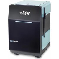
WXR 3030 - Welding machine Weller - Free user manual and instructions
Find the device manual for free WXR 3030 Weller in PDF.

User questions about WXR 3030 Weller
0 question about this device. Answer the ones you know or ask your own.
Ask a new question about this device
Download the instructions for your Welding machine in PDF format for free! Find your manual WXR 3030 - Weller and take your electronic device back in hand. On this page are published all the documents necessary for the use of your device. WXR 3030 by Weller.
USER MANUAL WXR 3030 Weller
GB Translation of the original instructions
natural_image
Circular icon with a lowercase 'i' in the center, commonly used to denote information (no additional text or symbols)
text_image
Weller www.weller-tools.comwww.weller-tools.com
text_image
Weller®MANUALFAQ

VIDEO


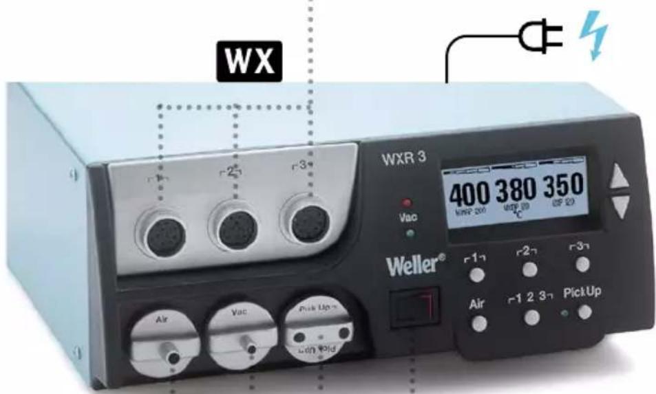
WXR 3

natural_image
Simple line drawing of an open box with a dotted arrow pointing upward (no text or symbols)
text_image
Weller® PROJ 1 10. Translational amplifier 11. Translational amplifier 12. Translational amplifier 13. Translational amplifier 14. Translational amplifier 15. Translational amplifier 16. Translational amplifier 17. Translational amplifier 18. Translational amplifier 19. Translational amplifier 20. Translational amplifier 21. Translational amplifier 22. Translational amplifier 23. Translational amplifier 24. Translational amplifier 25. Translational amplifier 26. Translational amplifier 27. Translational amplifier 28. Translational amplifier 29. Translational amplifier 30. Translational amplifier 31. Translational amplifier 32. Translational amplifier 33. Translational amplifier 34. Translational amplifier 35. Translational amplifier 36. Translational amplifier 37. Translational amplifier 38. Translational amplifier 39. Translational amplifier 40. Translational amplifier 41. Translational amplifier 42. Translational amplifier 43. Translational amplifier 44. Translational amplifier 45. Translational amplifier 46. Translational amplifier 47. Translational amplifier 48. Translational amplifier 49. Translational amplifier 50. Translational amplifier
natural_image
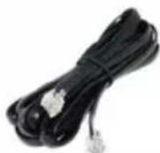
Coiled black cable with two connectors and a separate 3-pin connector (no text or symbols visible)
text_image
WEX 3 400 380 350 Weller® Air 2 3x PickUp
PC
T005 87 647 11
WFE/WHP
T005 87 647 12
WX
T005 87 647 10
WX Hub
T005 87 647 26
WX Foot switch
T005 87 647 46
WXSB 200
WHP 1000
WHP 3000, 600 W
WHP 3000, 1200 W
WXHP 120, 120 W
natural_image
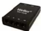
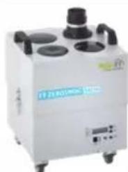
White industrial vacuum cleaner with four circular venters and black fittings (no visible text or symbols)Zero Smog 6V / WFE 4S
Zero Smog 20T / WFE 20D
Zero Smog 4V
WFV 60A
T005 87 627 46
Air

WXHAP 200
text_image
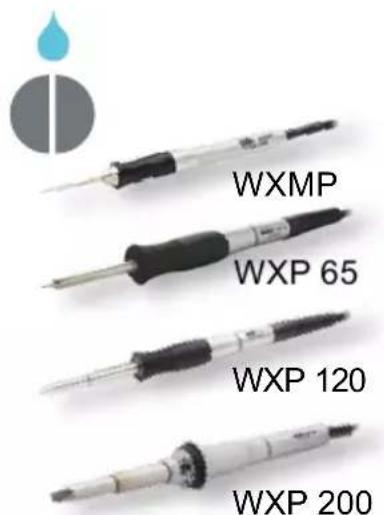
WXMP WXP 65 WXP 120 WXP 200Vac


text_image
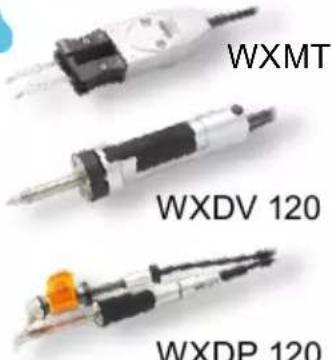
WXMT WXDV 120 WXDP 120Air
text_image
WX WXR 3 400 380 350 WNR 200 WBP 20 OP 20 Vac Weller® Air Vac Pick Up with volg Air PickUp
ON / OFF I/O
Pick Up
text_image
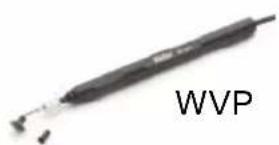
WVP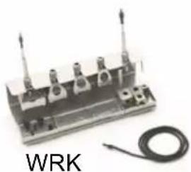
natural_image
Electrical component with three vertical posts and a coiled wire, labeled 'WRK' (no other text or symbols visible)Quick Reference WXR 3

flowchart
graph TD
    A["1"] --> B["1"]
    C["2"] --> D["2"]
    E["3"] --> F["3"]
    G["Air"] --> H["+/-"]
    I["Pick Up"] --> J["1 2 3"]
    K["Pick Up ON/OFF"] --> L["1/2/3"]
    M["OFF/ON"] --> N["+/-"]
    style A fill:#ccc,stroke:#333
    style C fill:#ccc,stroke:#333
    style E fill:#ccc,stroke:#333
    style G fill:#ccc,stroke:#333
    style I fill:#ccc,stroke:#333
    style K fill:#ccc,stroke:#333
    style M fill:#ccc,stroke:#333
    style K fill:#ccc,stroke:#333
DE Menüaufruf
GB Open Menu
ES Acceso al Menú
FR Appel du menu
IT Richiama il menu
flowchart
graph TD
    A["5s 5s"] --> B["△ + ▽"]
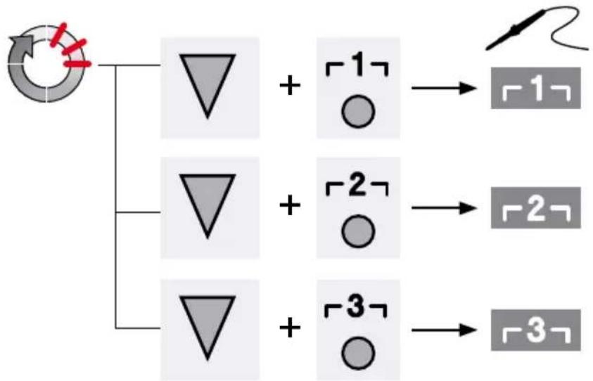
flowchart
graph TD
    A["Start"] --> B["△ + □ ○"]
    A --> C["△ + □ ○"]
    A --> D["△ + □ ○"]
    B --> E["→ □"]
    C --> F["→ □"]
    D --> G["→ □"]
USB COM 1
COM 2
text_image
8 - OK - 380 380 380 WXHAP 200 WXDP 120 WXP 120 on |+| °C DL |+| on WFE 1 5 7 COM 1 COM 2 Off Auto-Off Standby 5 1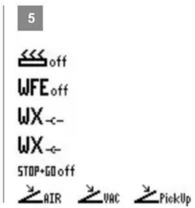
text_image
5off
WFE off WX _c- WX _c- STOP+GO off AIR VAC PickUpDE Schnittstelle COM 1 / COM 2
GB Interface COM 1 / COM 2
ES Interfaz COM 1 / COM 2
FR Interface COM 1 / COM 2
IT Interfaccia COM 1 / COM 2
PT Interface COM 1 / COM 2
NL Interface COM 1 / COM 2
SV Gränssnitt COM 1 / COM 2
DK Interface COM 1 / COM 2
FI Liittymä COM 1 / COM 2
GR Θύρα διεπαφής COM 1/COM 2
TR Arabirim COM 1 / COM 2
CZ Rozhraní COM 1 / COM 2
PL Interfejs COM 1 / COM 2
HU Interfész COM 1 / COM 2
SK Rozhranie COM 1 / COM 2
SL Vmesnik COM 1 / COM 2
EE Liides COM 1 / COM 2
LV Saskarne COM 1 / COM 2
LT Sasaja COM 1 / COM 2
BG Интерфейс COM 1 / COM 2
RO Interfață COM 1 / COM 2
HR Sučeljé COM 1 / COM 2
RU Интерфейс COM 1 / COM 2
6 WFV 60A
DE Zustandsanzeige
GB Status indication
ES Indicación del estado
FR Indication d'état
IT Indicatore di stato
PT Indicação de status
NL Statusweergave
SV Statusvisning
DK Statusindikator
FI Tilanneilmaisin
GR Ενδειξη προόδου
TR Durum göstergesidir
CZ Zobrazení stavu
PL Wyświetlacz stanu
HU Állapot kijelző
SK Zobrazenie stavu
SL Prikaz stanja
EE Olekuekraan
LV Stāvokla displejs
LT Büklès indikatorius
BG Индикация на състоянието
RO Afişaju de stare
HR Prikaž stanja
RU Индикация состояния
7 DE DATA LOGGER (DL) aktiv
GB DATA LOGGER (DL) active
ES DATA LOGGER (DL) activo
FR DATA LOGGER (DL) actif
IT DATA LOGGER (DL) attivo
PT REGISTO DE DADOS (DL)
activo
NL DATA LOGGER (DL) actief
SV DATA LOGGER (DL) aktiv
DK DATA LOGGER (DL) aktiv
FI DATA LOGGER (DL) aktivoitu
GR DATA LOGGER (DL) ενεργό
TR VERİ GÜNLÜKLEYİCİ (DL) aktif
CZ DATA LOGGER (DL) aktivní
PL DATA LOGGER (DL) aktywny
HU DATA LOGGER (DL - adatnap-
lózás) aktív
SK DATA'LOGGER (DL) aktivny
SL DATA LOGGER (DL) je aktiviran
EE DATA LOGGER (DL) on aktiivne
LV DATU REGISTRETAS (DR)
ir ieslegts
LT Aktyvintas duomenų registravimo jtaisas DATA LOGGER (DL)
BG DATA LOGGER (DL) активна
.RO DATA LOGGER (DL) activ
HR DATA LOGGER (DL) aktiviran
RU РЕГИСТРАТОР ДАННЫХ (РД) активирован
8 2 CH 1, 2, 3
DE Indikator Schaltausgang
GB Switching output indicator
ES Indicador salida de conexión
FR Indicateur sortie de commutation
IT Indicatore uscita di commu-
tazione
PT Indicador da saída de comutação
NL Indicator schakeluitgang
SV Indikator kopplingsutgång
DK Indikator koblingsudgang
FI Kytkentälähdön ilmaisin
GR Δείκτης επαφής εξόδου
TR Devre çıkışı göstergesi
CZ Indikátor spínacího výstupu
PL Wskaźnik wyjścia przełączającego
HU Kapcsolókimenet indikátor
SK Indikátor spínacieho výstupu
SL Indikator izhoda
EE Lülitusväljundi indikaator
LV Slēguma izejas indikators
LT Indikatoriaus jungimo išvadas
BG Включване индикатор изход
RO Indicator ieşire de comutare
HR Indikator prekidača za izlaz
RU Индикатор коммутируемого выхода
DE Inbetriebnahme
GB Starting up the device
natural_image
Illustration of a beige electronic device with control knobs and a digital display (no visible text or symbols)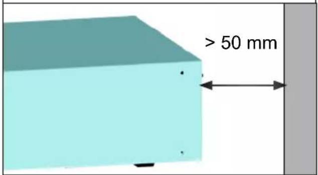
text_image
> 50 mm2

max. 3x
natural_image
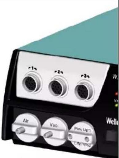
Close-up of a portable electronic device with three labeled ports (Air, Vac, Pie Up) and a teal cover, no readable text or symbols beyond labels.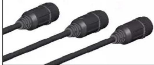
natural_image
Three black plastic connectors with threaded ends, shown in 3D rendering (no text or symbols visible)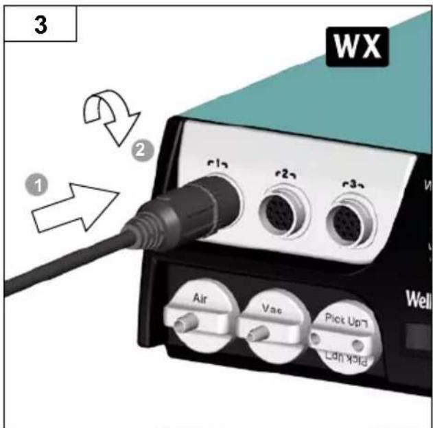
text_image
3 WX 1 2 r12 r22 r32 Air Vac Pick Up7 Lan Yold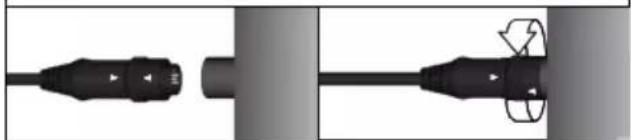
natural_image
Pure electrical connector diagram without any text, numbers, or symbols4

natural_image
Illustration of a motor with a green checkmark indicating inspection or certification (no text or symbols present)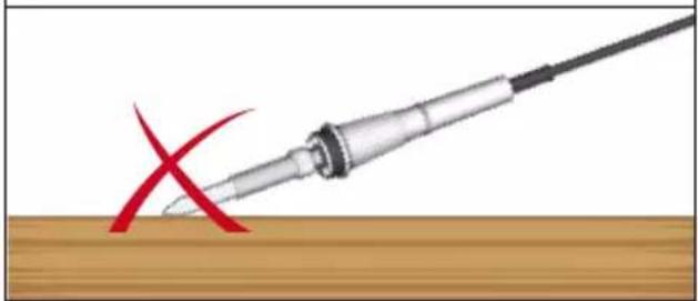
natural_image
Illustration of a soldering iron with a red X mark on a wooden surface (no text or symbols)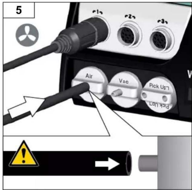
text_image
5 Air Vao Pick Up Lon koid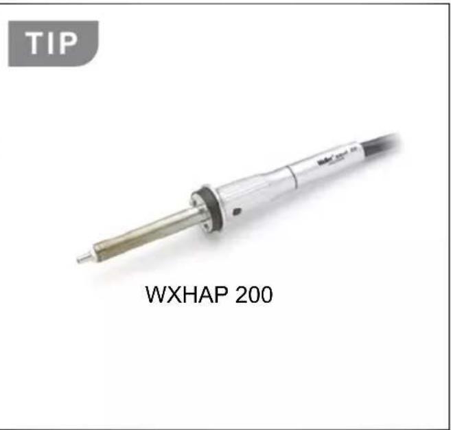
text_image
TIP WXHAP 200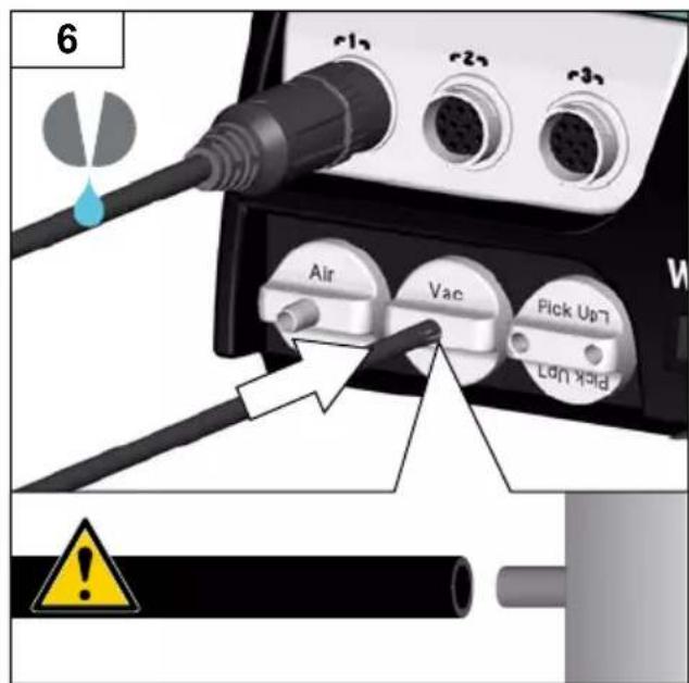
text_image
6 Air Vac Pick Up7 Lock Hold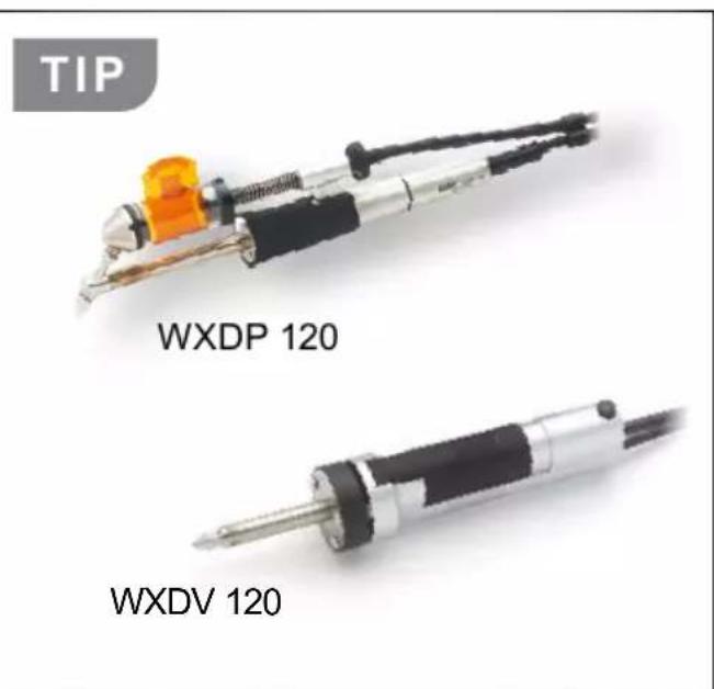
text_image
TIP WXDP 120 WXDV 120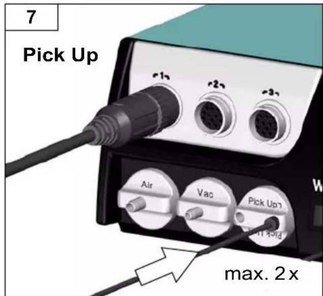
text_image
7 Pick Up r12 r22 r32 Air Vac Pick Up max. 2 x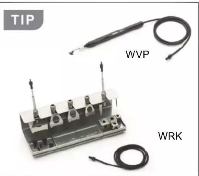
text_image
TIP WVP WRK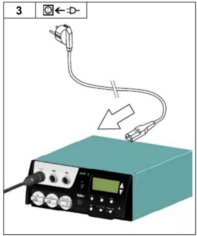
text_image
3 ←→-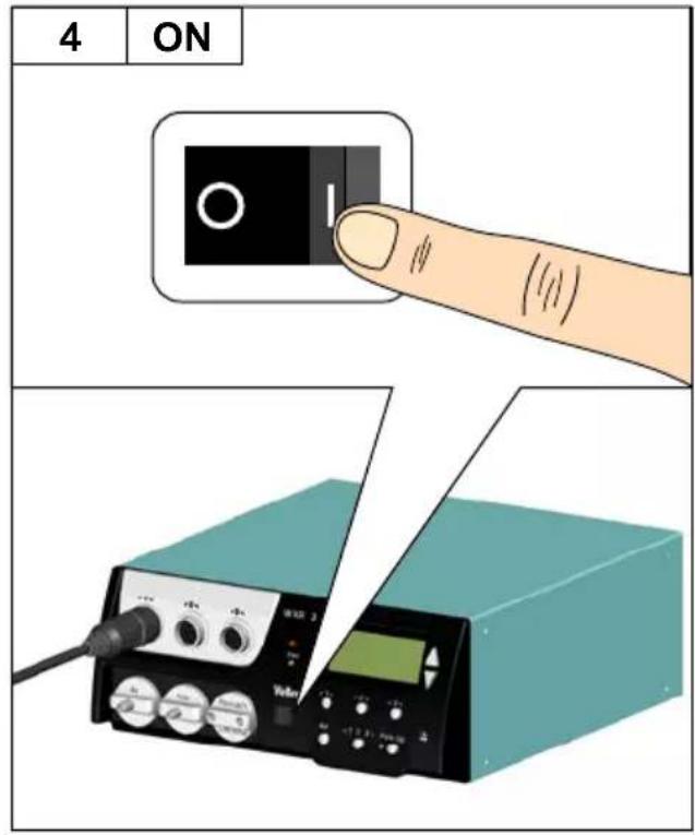
text_image
4 ON Vaser 2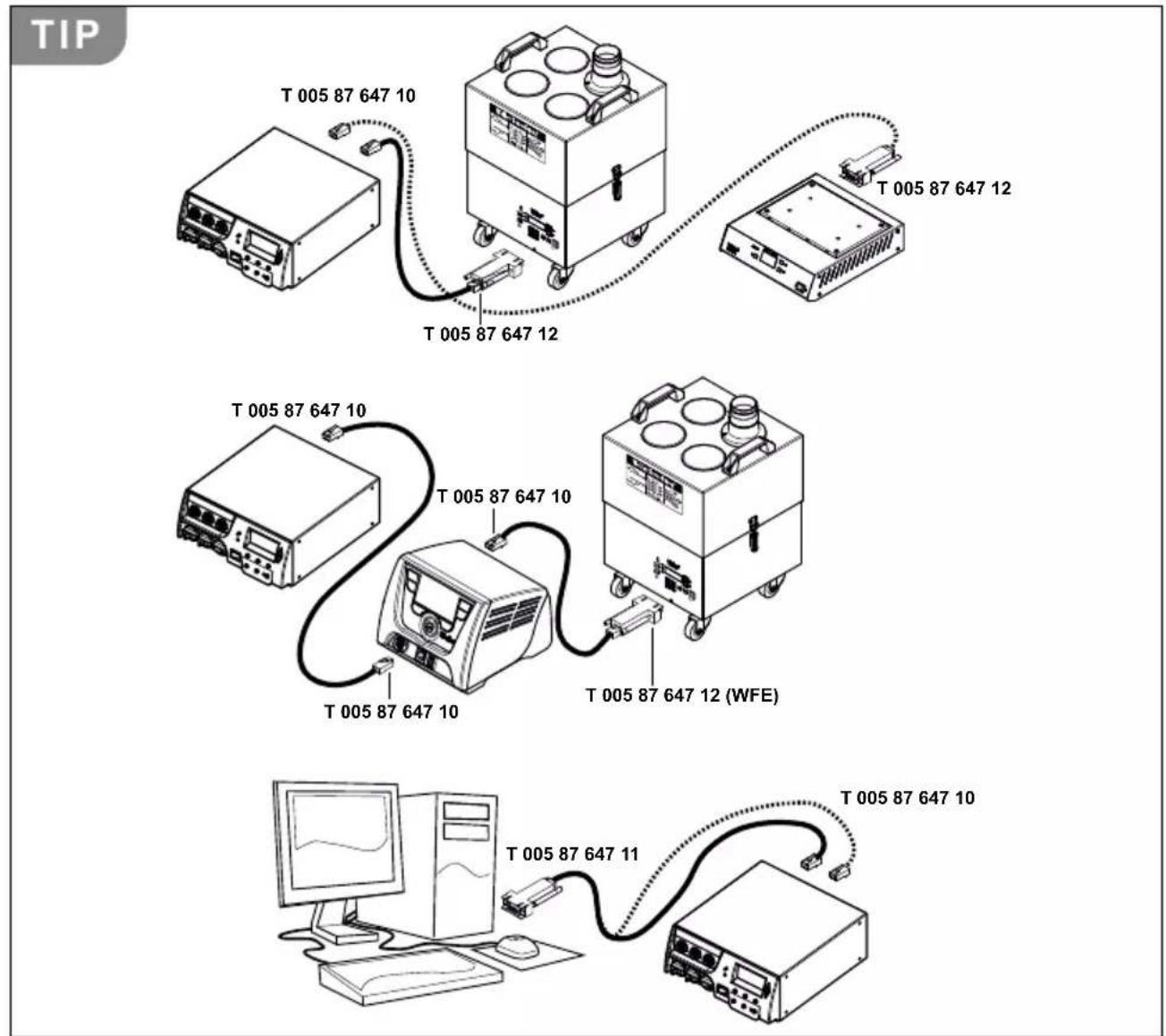
text_image
TIP T 005 87 647 10 T 005 87 647 12 T 005 87 647 12 T 005 87 647 10 T 005 87 647 10 T 005 87 647 10 T 005 87 647 12 (WFE) T 005 87 647 10 T 005 87 647 11 T 005 87 647 10DE Filterwechsel
GB Filter change
ES Cambio de filtr
text_image
2 +1 +2 +3 WXR 3 Vac Weller® Made in Germany r-1q Air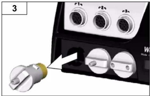
natural_image
Close-up of a device's electrical connector with three connected ports and a separate terminal block (no visible text or symbols)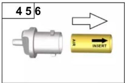
text_image
4 5 6 AIR INSERT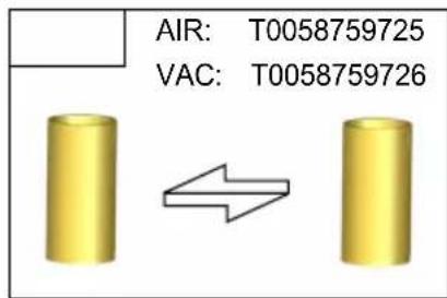
text_image
AIR: T0058759725 VAC: T0058759726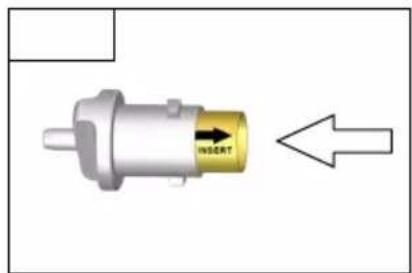
text_image
INSERT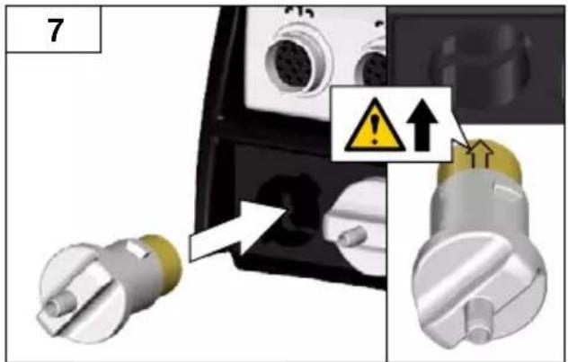
text_image
7 Warning ↑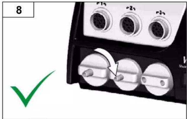
text_image
8 r1 r2 r3 v MadeDE Kanal auswählen
GB Select channel
text_image
Safety warning diagram showing a flame symbol on a cube with red X mark indicating explosion or damageDE Pick Up - Vakuum
GB PickUp vacuum
ES Pick Up - Vacío
FR Pick Up - vide
IT Vuoto Pick-up
PT Vácuo PickUp
NL Pick Up - vacuum
SV PickUp-vakuum
DK Pick Up - vakuum
FI Pick Up - tyhjiö
GR Pick Up - Kevó
TR Kaldırma vakumu
CZ Pick-up vakuum
text_image
TIP WVP WRK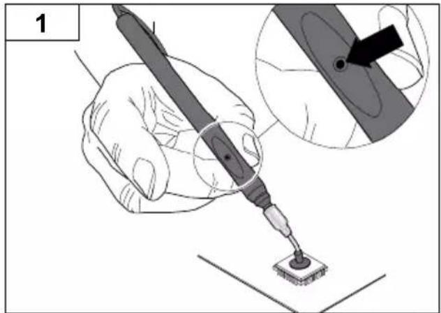
text_image
1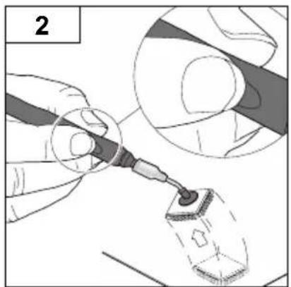
natural_image
Illustration of a gloved hand using a tool to apply material, showing a magnified view (no text or symbols)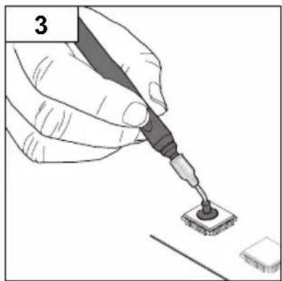
natural_image
Illustration of a hand using a power tool to apply soldering onto a surface (no text or symbols visible)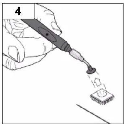
natural_image
Illustration of a hand using a power tool to apply a small component onto a surface (no text or symbols visible)GB Switching the channel on/ off
GB Nominal temperature
text_image
1 -1-/2-3- WXR 3 Vsc WXHAP 200°380°C 380 Exit 380 350 Weller Air Pick Up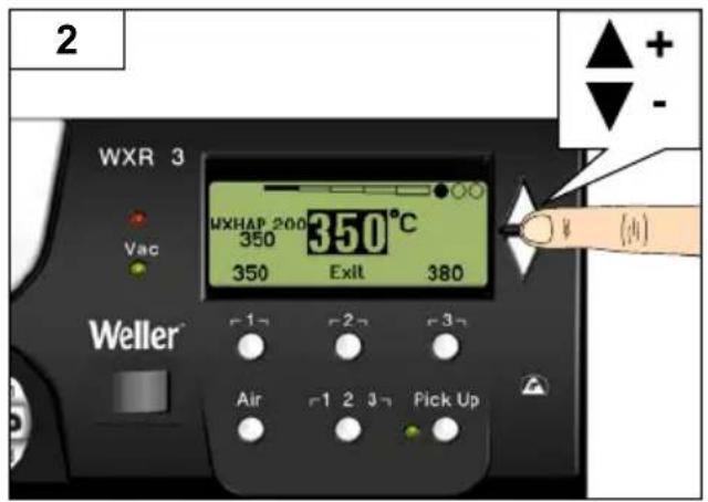
text_image
2 WXR 3 VAC WXHAP 200 350°C 350 Exit 380 Weller Air 1 2 3 Pick Up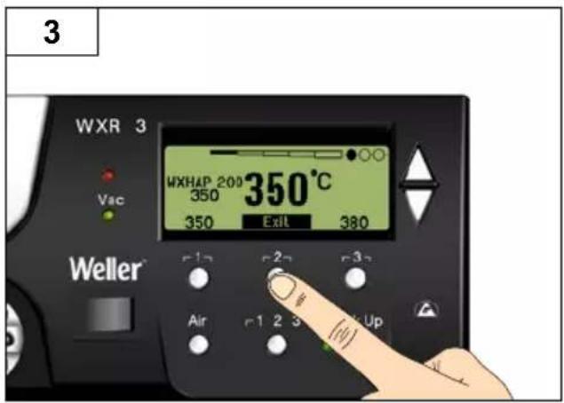
text_image
3 WXR 3 Vac WXHAP 200 350°C 350 350 Exit 380 Weller r1 r2 r3 Air r1 2 3 Up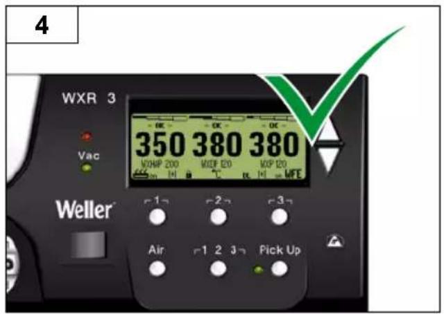
text_image
4 WXR 3 Vac 350 380 380 WORHP 200 WDEP E20 WDP E20 WFE Weller Air 1 2 3 Pick UpGB Select fixed temperature
GB Set and save fixe temperature
text_image
2 WXR 3 VAC WXHAP 200 350 380 Exit 350°C 400 Weller Air 1 2 3 Pick Up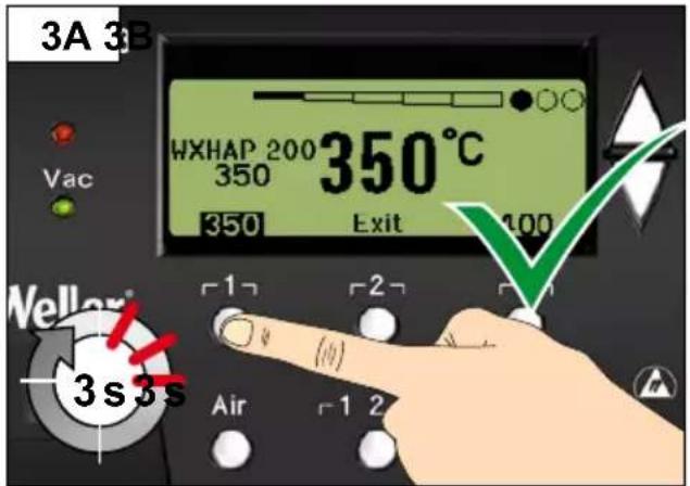
text_image
3A 3B HXHAP 200 350°C 350 350 Exit 100 Vac Weller® 3s3s Air 1 2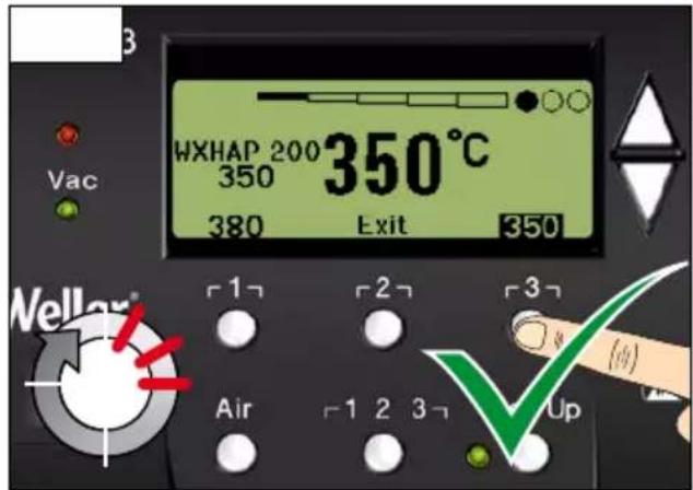
text_image
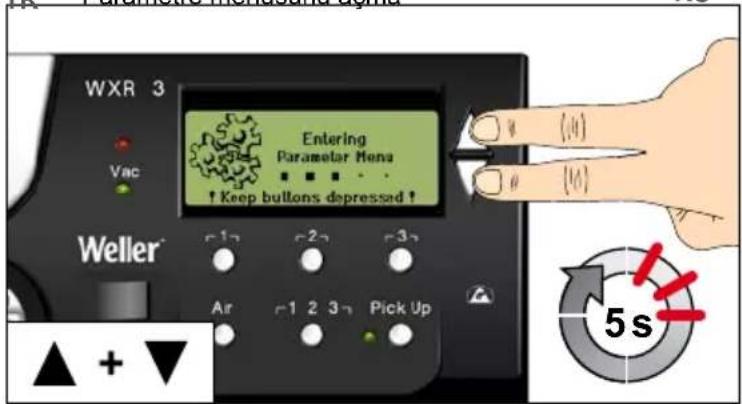
HXHAP 200 350°C 350 380 Exit 350 Weller® Air 1 2 3 4 Up| DE | Aufruf Parametermenü | CZ | Spuštění Nabídky položek Parametry |
| GB | Open Parameter menu | PL | Wywołanie menu parametrów |
| ES | Acceso al Menú de parámetros | HU | Paramétermenü előhívása |
| FR | Appel du menu Paramètres | SK | Vyvolanie menu parametrov |
| IT | Richiama il menu Parametri | SL | Priklic menija parametrov |
| PT | Activação do menu de parâmetros | EE | Parameetrimenüü avamine |
| NL | Oproep parametermenu | LV | Parametru izvēlnes izsaukšana |
| SV | Öppna parametermenyn | LT | Parametrų meniu iškvieta |
| DK | Hentning af parametermenu | BG | Разпределение на бутоните |
| FI | Parametrivalikon haku näyttöön | RO | Alocarea tastelor |
| GR | Klήση μενού των παραμέτρων | HR | Dodjela tipki |
| IR | Parametre menüsünü acma | RU | Вызов меню параметров |
text_image
WXR 3 Vac Entering Parametar Menu ↑ Keep buttons depressed ↑ Weller r12 r22 r32 Air r1 2 3 n Pick Up ▲ + ▼ (4) (4) 5s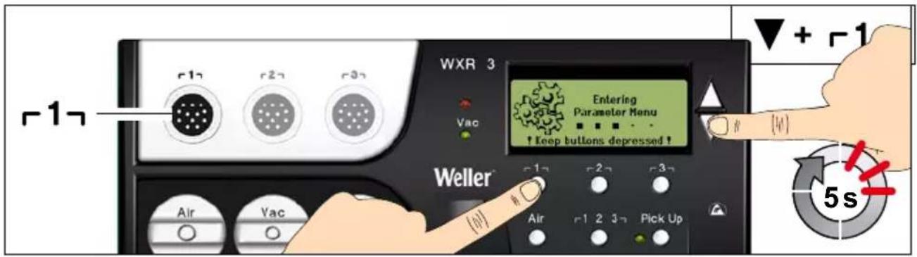
text_image
WXR 3 Entering Parameter Menu ↑ keep buttons depressed ! Weller Air Vac Air 2 3 Pick Up + -1 5s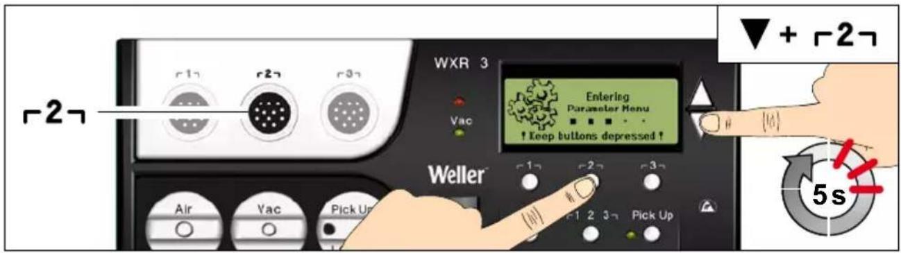
text_image
WXR 3 Entering Parameter Menu ↑ Keep buttons depressed ↑ Weller Air Vac Pick Up 1 2 3 4 Pick Up ▼ + -2- 5s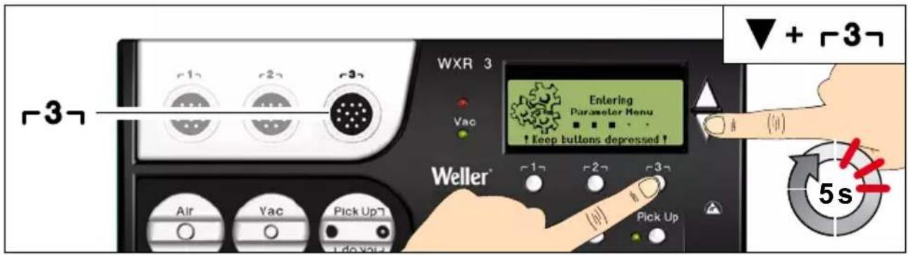
text_image
WXR 3 Entering Parameter Menu ! Keep buttons depressed ! Weller* Air Vac Pick Up Pick Up -3- + -3- 5stext_image
WXR 3 Solution Parameters Language ENG Unit °C Password *** Exit Weller Air -1 2 3 Pick UpDE Parametermenü verlassen
GB Exit parameter menu
Max. Heißluftdauer WXHAP

Menüaufruf ▶ Tool-Parameter
Thank you for the confidence you have shown in buying this device.
The device has been manufactured in accordance with the most rigorous quality standards which ensure that it operates perfectly.

Read these instructions and the accompanying safety information carefully before starting up the device starting work with the device.
Keep these instructions in a place that is accessible to all users.
These instructions contain important information which will help you to start up, operate and service the device safely and correctly as well as to eliminate simple faults and malfunctions yourselves.
The device has been manufactured in accordance with state-of-the-art technology and acknowledged regulations concerning safety.
There is nevertheless the risk of personal injury and damage to property if you fail to observe the safety information set out in the accompanying booklet and the warnings given in these instructions.
Safety information
For safety reasons, children and youths under the age of 16, as well as persons who are not familiar with these operating instructions, may not use the device. Children should be supervised in order to ensure that they do not play with the tool.
This device is not intended for use by persons (including children) with limited physical, sensory or mental aptitude, or by persons who lack knowledge or experience in handling the device.

Warning! Electrical shock
Connecting the control unit incorrectly poses a risk of injury due to electric shock and can damage the device.
Carefully read the attached safety information, the safety information accompanying these operating instructions as well as the operating instructions for your control unit before putting the control unit into operation and observe the safety precautions specifie therein.
■ Only connect WELLER WX tools.
- Never use the USB port as a power supply for third-party devices.
If the device is faulty, active electrical conductors may be bare or the PE conductor may not be functional.
■ Repairs must always be referred to a Weller-trained specialist.
If the electrical tool's power supply cord is damaged, this must be replaced with a specially prefabricated power supply cord available through the customer service organisation.

Warning! Risk of burns
Risk of burns from the soldering tool while the control unit is operating. Tools may still be hot long after they have been switched off.
■ Always place the soldering tool in the safety rest while not in use.
- Only connect the vacuum and hot air at the designated points.
- Do not direct hot air soldering tools at people or inflammable objects.

Warning! Fire and explosion hazard! Hot tools represent a fire hazard
■ Always place the soldering tool in the safety rest while not in use.
Do not direct hot air soldering tools at people or inflammable objects.
- Keep explosive and flammable objects well away from the device.
Do not cover the device.
Specified Conditions Of Use
Supply unit for WELLER WX soldering tools. Use the repair station only for the purpose indicated in the operating instructions of soldering and desoldering under the conditions specific herein.

Flammable gases and liquids may not be extracted.
The device may only be used with correctly fitte and suitable filte cartridges.
Replace filte cartridges when full.
Only use the device indoors. Protect against moisture and direct sunlight.
Intended use of the soldering station/ desoldering station also includes the requirement that you
■ adhere to these instructions,
■ observe all other accompanying documents,
■ comply with national accident prevention guidelines applicable at the place of use.
The manufacturer will not be liable for unauthorised modification to the device.
User groups
Due to differing degrees of risk and potential hazards, several work steps may only be performed by trained experts.
| Work step User groups | |
| Default soldering parameters Specialist personnel with technical training | |
| Replacing electrical replacement parts Electricians | |
| Default maintenance intervals | Safety expert |
| OperationFilter change | Non-specialists |
| OperationFilter changeReplacing electrical replacement parts | Technical trainees under the guidance and supervision of a trained expert |
Starting up the device
Caution!
Please adhere to the operating instructions of the connected devices.
Put the tool into operation as described in the chapter „Placing into operation“.

Check to see if the mains voltage matches the ratings on the nameplate.
Make sure the machine is switched off before plugging in.
After switching on the device, the microprocessor carries out a self-test and reads out the values of the parameters stored in the tool.
The set-point temperature and fixe temperatures are stored in the tool. The actual temperature value increases to the set-point temperature (= soldering tool is heated up).
Soldering and desoldering
Carry out soldering work as directed in the operating instructions of your connected soldering tool.
Handling the soldering tips
Coat the selective and tinnable soldering tip with solder when heating it up for the first time. This removes oxide coatings which have formed during storage and impurities from the soldering tip.
■ Make sure that the soldering tip is well coated with solder during breaks between soldering work and prior to storage of the device.
- Do not use aggressive fluxin agents.
■ Always make sure that the soldering tips are fitte properly.
- Select as low a working temperature as possible.
- Select the largest possible soldering tip shape for the application.
Rule of thumb: the soldering tip should be roughly as large as the soldering pad.
- Coat the soldering tip well with solder to ensure
that there is efficient heat transfer between the soldering tip and the soldering area.
Prior to extended breaks between soldering work, switch off the soldering system or use the Weller function to reduce the temperature when the soldering equipment is not in use.
- Coat the tip with solder prior to storage if you do not intend to use the soldering iron for an extended period of time.
- Apply solder directly to the soldering area, not to the soldering tip.
- Change the soldering tips using the designated tool.
- Do not apply mechanical force to the soldering tip.
Notice
The control units have been adapted to hold a medium-sized soldering tip. Discrepancies may occur if the tip is changed or a different shaped tip is used.
Overload cut-out
To avoid overloading the station, power output is automatically reduced in the event of an overload.
Equipotential bonding
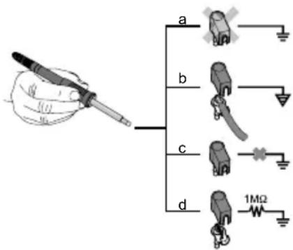
text_image
a b c d 1MΩFour variants are possible by connecting the 3.5 mm jack socket differently:
| a Hard-grounded supplied | without plug. |
| b Equipotential bonding | with plug, equaliser at centre contact. |
| c Floating with plug | |
| d Soft-grounded with plug | and soldered resistor. Ground-ed through selected resistor. |
Carrying out a firmware update
Notice
The station must not be switched off while the firmware update is running.
Switch off station 1.
- Insert the memory stick into the USB port.
Switch on station 3.
The firmwar update is performed automatically. If you have a more already installed more recent firmwar on your station, this will not be changed.
Care and maintenance

Warning!
Before doing any work on the machine, pull the plug out of the socket.

Warning!
Use original replacement parts only.

Warning! Risk of burns
■ Only replace solder tips when cold
- Replace and clean suction nozzles only when hot and using the suitable tool
■ Only replace hot air nozzles using the suitable tool
■ Only clean or replace solder collection tubes when cold
Clean the operator panel, if dirty, using a suitable cleaning cloth.
Filter change
Check the filte regularly for contamination, and replace it if necessary.
Warning!
Failure to use a filte will cause irreparable damage to the vacuum pump.
- Check before starting soldering whether a main filte is inserted.
Contaminated filters must be treated as special waste.
Dispose of replaced equipment parts, filters or old devices in accordance with the rules and regulations applicable in your country.
Wear suitable protective gear.
Standby Temp.

Menu access ▶ Tool parameters
The soldering tools have a usage detection device (sensor) in the handle which automatically initiates cooling to Standby temperature when the soldering tool is not in use.
Z
Standby time (temperature deactivation)

Menu access ▶ Tool parameters
When the soldering tool is not in use, the temperature is reduced to Standby temperature on expiration of the set Standby time. The display reads „Standby“.
Press control key to exit Standby mode. The sensor integrated tool detects the change in state and deactivates Standby mode as soon as the tool is moved.
| Option Description | |
| OFF | standby time is deactivated (factory setting) |
| 1-999 min | standby time, individually adjustable |
| --- The tool | is not supported |
AUTO OFF time (automatic switch-off time)

Menu access ▶ Tool parameters
When the soldering tool is not in use, the soldering tool heater is switched off when the AUTO OFF time expires.
Temperature deactivation is performed independently of the set standby function. The actual temperature is indicated and serves as a residual heat display. The display reads „AUTO OFF“.
| Option Description | |
| OFF AUTO | OFF function is deactivated (factory setting) |
| 1-999 min | AUTO-OFF time, can be set individually. |
Sensitivity

Menu access ▶ Tool parameters
Option Description
| low | Non-sensitive – Reacts to heavy (long) movement |
| normal standard (factory setting) | |
| high Sensitive - Reacts to light (short) movement | |
| --- The tool is not supported | |
Max. hot air duration WXHAP

Menu access ▶ Tool parameters
The on-time of the hot air flow of the WXHAP can be limited in increments of 1 to between 0 and 300 sec. The factory default is 0 s („OFF“), i.e. air flow only as long as the button on the hot air tool or the optional footswitch is pressed.
| Option Description | |
| OFF | No duration define (factory setting) |
| 1-300 s | Individually adjustable |
Offset (Temperature-Offset)

Menu access ▶ Tool parameters
The actual soldering-tip temperature can be adapted by entering a temperature offset around ±40^ ( ±72^ ).
Perform. Mode
Menu access ▶ Tool parameters
The function determines the heating characteristics of the soldering tool to achieve the set tool temperature.
| Option Description | |
| standard | adapted (medium) heating (factory setting) |
| min. slow heating | |
| max. rapid heating | |
Button lock WXHAP
Menu access ▶ Tool parameters
This function can be used to adjust the factory button presets of the WXAHP tool.
| Option Description | |
| OFF - | |
| ON | The WXHAP is switched on the first time the button is pressed and switched off the next time the button is pressed. |
Process window
Menu access ▶ Tool parameters
The temperature range set in the process window determines the signal response of the floatin switching output.
Notice
On tools with an LED ring light (e.g. WXDP 120), the process window defines the illumination characteristics of the LED ring light.
If the LED is continuously illuminated, this means that the preselected temperature has been reached or that the temperature is within the predetermined process window.
A flashing LED indicates that the system is heated or that the temperature is outside the process window.
Language
Menu access ▶ Station parameters
| CHN | 中文 |
| DEN Dansk | |
| ENG English | |
| ESP Español | |
| FIN | Suomi |
Temperature version °C/°F (temperature units)
Menu access ▶ Station parameters
Option Description
| °C | Celsius |
| °F | Fahrenheit |
Password (lock function)

Menu access ▶ Station parameters
After switching the lock function on, only the fixe temperature keys can be operated on the soldering station. All other settings are disabled until the repair station is unlocked again.
Notice
If you want only one temperature value to be selectable, the control keys fixed temperature keys) must be set to the same temperature value.
Locking the soldering station
Set the desired three-digit locking code (between 001 and 999) using the UP / DOWN buttons. Confir the code with the Enter key.
The lock is active (the display shows a lock symbol).
Unlocking the soldering station
- Call up the parameter menu. If the lock function is active, the password menu item opens automatically. Three stars ( ^*** ) are shown on the display.
- Set the three-digit locking code using the UP / DOWN buttons.
- Confir the code with the Enter key.
Forgotten code?
Please contact our Customer Service: technical-service@weller-tools.com
Single-channel display

Menu access ▶ Station parameters
To obtain more straightforward readings, the display mode from can switched from 3-channel display to 1-channel display.
If single-channel display is selected, the device does not reset automatically to 3-channel display after setting the temperature of a tool channel.
The display mode can be reset using 2 .
Option Description
| OFF | Automatic reset to 3-channel display (factory setting) |
| ON | No automatic reset to 3-channel display |
Vacuum pre-feed

Menu access ▶ Station parameters
In order to prevent the pump from starting prematurely or to ensure a define soldering-joint preheating time, it is possible to set an ON delay.
Option Description
| 0 sec OFF | vacuum pre-feed function is OFF (factory setting) |
| 1-10 sec | ON: vacuum pre-feed time, individually |
Vacuum run-on

Menu access ▶ Station parameters
To prevent the desoldering iron from becoming clogged, it is possible to set a vacuum run-on time.
Option Description
| 0 sec OFF | vacuum run-on function is OFF (factory setting) |
| 1-10 sec | ON: vacuum run-on time, individually adjustable |
Pressure gauge threshold

Menu access ▶ Station parameters
This function can be used to defin the maintenance interval of the desoldering tool. This is done by setting the value in mbar at which the electric pressure gauge issues a warning signal when the intake system is contaminated (LED of the vacuum pump switches from green to red). The set value is dependent on the suction nozzles used.
Adjustable -400 mbar to -800 mbar
factory setting -600 mbar
-
The system (tips and filter must be free.
-
Select the menu item „Pressure gauge threshold“ in the menu.
-
Set the "Pressure gauge threshold" pressure value with the UP or DOWN button. The status LED switches back and forth between red and green. Use the UP button to increase vacuum by 50 to 80 mbar, then pinch the vacuum tube and check whether the LED switches from green to red.
-
Adopting the set change.
Interface COM 1 / 2

Menu access ▶ Station parameters
Option Description
| RS232 | Serial communication with PC or other compatible Weller devices (factory setting). |
| Air | The COM 1 port is configure as a foot switch input for activating the air flo . |
| Vac | The COM 1 port is configure as a foot switch input for activating the vacuum. |
| PickUp | The COM 1 port is configure as a foot switch input for activating the PickUp vacuum. |
| Stop&Go The C | COM 1 port is used to drive an optional optotransmitter so that a KHE-P control unit can be activated via an optical fibreThe output is activated when a tool is used. In addition, the floatin switched output is closed. The output is off in the Standby, Auto Off or Off positions, or if no tool is inserted. |
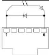
Floating switching output 1

Menu access ▶ Station parameters
Floating switching output 1 is located at the COM 1 port.
Option Description
| OFF | (factory setting) |
| ZeroSmog | The floatin switching output is closed when a tool is in use. Selected Zero Smog extraction systems can be connected using an optional adaptor (WX HUB). The rear RS 232 port remains functional.Switching output is open in the Standby, Auto Off or Off positions, or if no tool is inserted. |
text_image
1 6REAR RJ-Socket
max. 50 V / 20 mA
Notice
If the COM 1 port is also configured for „Stop&Go“ use, the „Filter full" message is evaluated by the WX HUB and, where applicable, a message appears on the display.
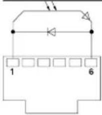
Floating switching output 2

Menu access ▶ Station parameters
Floating switching output 2 is located at the COM 2 port.
Option Description
| OFF | (factory setting) |
| CH 1 Tool channel 1 controls the switching output | |
| CH 1+2 Tool channel 1 + 2 controls the switching output | |
| CH 1+2+3 Tool channel 1 + 2 + 3 controls the switching output | |
text_image
1 6REAR RJ-Socket
max. 50 V / 20 mA
Notice
If the robot is at working temperature, the display will show - ok -.
Technical Data
| Repair station WXR 3 | |
| Dimensions L x W x H 273 x | 235 x 102 mm(10,75 x 9,25 x 4,02 inch) |
| Weight ca. 6,7 kg | |
| Mains supply voltage | 230 V, 50 Hz T0053500699120 V, 60 Hz WXR 3100 V 50/60 Hz T0053500199 |
| Power consumption 420 W (600 W) | |
| Safety class I, antistatic housing | III, Soldering tool |
| Fuse | Overcurrent release 230 V; 2,0 A120 V; 4,0 A |
| Temperature range Celsius: | 100 - 450°C (550°C)Fahrenheit: 200 - 850°F (999°F)Controllable temperature range is tool-dependent |
| Temperature accuracy | ± 9 °C (± 17 °F) Tool dependent (WXHAP 200 ±30 °C / ±80 °F) |
| Temperature stability | ± 2 °C (± 4 °F) |
| Equipotential bonding | Via 3.5 mm pawl socket on back of unit |
| Display | 240 x 88 dots / Backlighting |
| USB port | The control unit comes with a USB port for installing firmwar updates, configuratio and monitoring. |
| Pump (Intermittent mode (30/30) s) | Max. vacuum 0,7 barMax. delivery rate 18 l/minMax. hot air 15 l/min |
| Additional vacuum pump Max. | vacuum0,5 barMax. delivery rate 1,7 l/min |
Error messages and error clearance
| Message/symptom Possible cause | Remedial measures | |
| Display: „- - - | Tool has not been detectedTool defective | Check connection of tool to deviceCheck connected tool |
| No display function (display OFF) | No mains supply voltage | Turn on mains power switchCheck mains supply voltageCheck device fuse |
| No vacuum at desoldering tool | Vacuum not connectedDesoldering nozzle cloggedPump faulty | Connect vacuum hose to vacuum connectionService desoldering nozzle using cleaning tool |
| Insufficient vacuum at desoldering tool | Filter cartridge on desoldering tool fullMain filte full | Change filte cartridge on desoldering tool fullChange the main filte element on the soldering station |
| Hot air tool has no air | Air hose not connectedMain filte full | Connect or check air hoseChange main filte cartridge on soldering station |
Symbols
| Caution! | |
| Read the operating instructions! | |
| Before performing work of any kind on the unit, always disconnect the power plug from the socket. | |
| ESD-compatible design and ESD-compatible workstation | |
| Equipotential bonding | |
| Fuse | |
| Safety transformer | |
| CE mark of conformity | |
| British Conformity Mark |


Warranty
Claims by the buyer for physical defects are time-barred after a period of one year from delivery to the buyer. This does not apply to claims by the buyer for indemnification in accordance with §§ 478, 479 BGB (German Federal Law Gazette).
We shall only be liable for claims arising from a warranty furnished by us if the quality or durability warranty has been furnished by use in writing and using the term „Warranty“.
The warranty shall be void if damage is due to improper use and if the device has been tampered with by unauthorised persons.
Subject to technical alterations and amendments.
For more information please visit www.weller-tools.com.
Coupure de surcharge
Enote temperature °C/°F
Priklic menija ▶ Parametri postaje
Opcija Opis
| °C | Celzij |
| °F | Fahrenheit |
EN EC declaration of conformity
We hereby declare that the products described herein comply with the following guidelines:
We hereby declare that the products described herein comply with the following guidelines:
2004/108/EG, 2011/65/EU (RoHS), 2006/42/EG

Besigheim, 2023-08-30
Philippe Buidin
Managing director
Authorised to compile technical documentation.
Authorised to compile technical documentation.
Apex Tool Group UK Ltd
Registered in England,
Company Number 14127816
Registered Office:
C/O TMF Group 13th Floor,
One Angel Court, London,
EC2R 7HJ, United Kingdom
Weller Tools GmbH
Product Registration
text_image
Weller INDUSTRIAL SOLDERING TOLERATION PRECISION TOOLS SOLDERING SERVICE SUPPLY COMMER CONTACT REQUEST LOCAL Registration: Title* Print name* LATE NAME* Complete name* Phone Number* Country Region* Street address* Print code* City* Email* Registration Details: Product type* Performance or Credit Serial Name* Applications? Hardware name* Distributions* Product Type Weller CE UK CA Apex Tool Group UK Ltd Reg in England, Company No. 14127816 20 Farrington Street, 8th Floor London, EC4A 4AB, United Kingdom Weller Tools GmbH Carl-Benz-Str. 2 D-74354 Besigheim Made in Hungary Designed & Engineered in Germany Serial Numberwww.weller-tools.com/registration

GERMANY
Weller Tools GmbH
Carl-Benz-Straße 2
74354 Besigheim
Apex Tool Group B. V.
Apex Tool Group UK Ltd
Registered in England,
Company Number 14127816
Registered Office:
C/O TMF Group 13th Floor,
One Angel Court, London,
EC2R 7HJ, United Kingdom
USA
Apex Tool Group, LLC.
Weller Professional Tools Division
1000 Lufkin Road
Apex, NC 27539
+866-498-0484