BELLE RPC 30 - Vibratory plate Lescha - Free user manual and instructions
Find the device manual for free BELLE RPC 30 Lescha in PDF.
| Product type | Reversible vibrating plate |
| Brand | Lescha (Belle Group) |
| Model | BELLE RPC 30 |
| Plate width | 400 mm (model 30/40) or 500 mm (model 30/50) |
| Dimensions (L × W × H) | 657 × 400/500 × 1265 mm |
| Weight | From 154 to 200 kg depending on engine |
| Centrifugal force | 30 kN |
| Vibration frequency | 90 Hz |
| Max. travel speed | Greater than 23 m/min |
| Sound level | 108 dB(A) |
| Available engines | Petrol: Honda GX160 (5.5 hp), Robin EX17 (6 hp); Diesel: Hatz 1B20-6 (4.2 hp), Lombardini 15LD225 (4 hp) |
| Fuel | Unleaded petrol or diesel (depending on engine) |
| Petrol tank capacity | 3.6 L (petrol engines) |
| Diesel tank capacity | 2.5 L (Lombardini); see manual for Hatz |
| Engine oil | SAE 10W30; quantity: 0.6 L (Honda), 1.1 L (Robin), 0.9 L (Hatz), 0.8 L (Lombardini) |
| Gearbox oil | SAE 75W-90, 0.6 L |
| Hydraulic oil | Shell Tellus 32 or Fuchs Renolin MR520, 0.2 L |
| Clutch | Centrifugal |
| Steering control | Handle with forward/reverse reversal |
| Safety | Automatic engine stop if handle released; belt protection cover; lifting ring |
| Maintenance | Engine oil change every 50 h, air filter checked every 8 h, belt tension after 4 h of break-in then every 50 h |
| Spare parts | Available from the Belle Group network; use genuine parts to maintain warranty |
| Warranty | 1 year (12 months) for the original purchaser |
Frequently Asked Questions - BELLE RPC 30 Lescha
User questions about BELLE RPC 30 Lescha
0 question about this device. Answer the ones you know or ask your own.
Ask a new question about this device
Download the instructions for your Vibratory plate in PDF format for free! Find your manual BELLE RPC 30 - Lescha and take your electronic device back in hand. On this page are published all the documents necessary for the use of your device. BELLE RPC 30 by Lescha.
USER MANUAL BELLE RPC 30 Lescha
natural_image
Abstract white bird-like shape on gradient background (no text or symbols)ALTRAD
GB Operators Manual 6
US Operators Manual 14
F Manuel De L'Opérateur 22
E Manual del Operador 30
P Manual de Operação 38
NL Handleiding 46
DK Betjeningsvejledning 54
D Bedienungshandbuch 62
I Manuale Dell'Operatore 70
S Bruksanvisning 78
NO Betjene Håndbok 86
SF Käyttöohje 94
PL Instrukcja Obsługi 102
RUS Руководство для оператора 110
EST Kasutusjuhend 118
LV Lietotāja rokasgrāmata 126
LT Naudojimo Instrukcija 134
BG Оператор Ръчен 142
cz Na'vod K Obzluze 150
RO Manual de Utilizare 158
HUN Kezelők Kézi 166
HR Uputstvo za rukovatelja 174

text_image
Belle GROUP
text_image
RPC 30
natural_image
Technical line drawing of a mechanical device with no visible text or symbols182
- Spare Parts Book
- Pièces détachées
- Libro Despiece
- Lista de Peças
- Onderdelen Boekje
- Reservedele Skrift
- Ersatzteilhandbuch
- Manuale dei ricambi
- Bruksanvisning
- Bruksanvisning
- Varaosaluettelo
- Lista Części Zamiennych
- Запасные части Книга
- Varuosade nimekiri
- Rezerves daju saraksts
- Atsarginiu daliu sarašas
- Част Списък
- Část Barevný pruh
- Lista Pieselor de Schimb
- Részek Oldalra döl
- Rezervni djelovi Knjiga
EC DECLARATION OF CONFORMITY / DECLARATION CE DE CONFORMITE / DECLARACIÓN DE CONFORMIDAD CE / DECLARAÇÃO CE DE CONFORMIDADE / EG-VERKLARING VAN OVEREENSTEMMING / EF OVERENSSTEMMELSESERKLAERING

We, Belle Group Sheen UK, Sheen, Nr. Buxton, Derbyshire, SK17 0EU, GB, hereby certify that if the product described within this certificate is bought from an authorised Belle Group dealer within the EEC, it conforms to the following EEC directives: 98/37/EC (This directive is a consolidation of the original machinery directive 89/392/EEC), Electromagnetic Compatibility Directive 89/336/EEC (as amended by 92/31/EEC & 93/68 EEC). The low voltage directive 73/23/EEC, BS EN ISO 12100-1:2003 Safety of machinery and associated harmonised standards, where applicable. Noise emissions conform to directive 2000/14/EC Annex VI, for machines under article 12 the notified body is AV Technology Limited, AVTECH house, Birdhall Lane, Cheadle Heath, Stockport, Cheshire, SK3 0XU, GB. Noise Technical Files are held at the Belle Group Head Office address which is stated above.

Semnat de: Director General - in numele BELLE GROUP (SHEEN), UK
This manual has been written to help you operate and service the 'RPC' safely. This manual is intended for dealers and operators of the 'RPC'.
Foreword
The ‘Machine Description’ section helps you to familiarise yourself with the machine’s layout and controls.
The 'Environment' section gives instructions on how to handle the recycling of discarded apparatus in an environmentally friendly way.
The ‘General Safety’ and ‘Health and Safety’ sections explain how to use the machine to ensure your safety and the safety of the general public.
The 'Start and Stop Procedure' helps you with starting and stopping the machine.
The ‘Trouble Shooting Guide’ helps you if you have a problem with your machine.
The 'Service & Maintenance' section is to help you with the general maintenance and servicing of your machine.
The 'Warranty' Section details the nature of the warranty cover and the claims procedure.
The ‘Declaration of conformity’ section shows the standards that the machine has been built to.
Directives with regard to the notations.
Text in this manual to which special attention must be paid are shown in the following way:

CAUTION
The product can be at risk. The machine or yourself can be damaged or injured if procedures are not carried out in the correct way.

WARNING
The life of the operator can be at risk.

WARNING

WARNING
Before you operate or carry out any maintenance on this machine YOU MUST READ and STUDY this manual.
KNOW how to safely use the unit's controls and what you must do for safe maintenance. (NB Be sure that you know how to switch the machine off before you switch on, in case you get into diffi culty.)
ALWAYS wear or use the proper safety items required for your personal protection. If you have ANY QUESTIONS about the safe use or maintenance of this unit, ASK YOUR SUPERVISOR OR CONTACT: BELLE GROUP (UK): +44 (0) 1298 84606

Contents
How To Use This Manual 6
Warning 6
Machine Description....7
Technical Data....7
Environment 7
General Safety 8
Health and Safety 8
Pre-Start Checks 8
Reasons For Compaction....9
Start and Stop Procedure....9 - 10
Operating Instructions....10
Trouble Shooting Guide 11
Service & Maintenance 11 - 13
Warranty 13
Declaration of conformity....2

text_image
1 2 3 4 5 6 7 8 A B C- Throttle lever.
- Recoil Starter Handle.
- Fuel Tank.
- Lifting Point.
- Handle Release Catch.
- Forward / Reverse Control Handle.
- Main Handle.
- Belt Guard.
Technical Data

| Model | 30/40 | |
| A - Plate Width mm | 400 | |
| B - Height mm | 1265 | |
| C - Length mm | 657 | 657 |
| Engine - Honda Petrol (Hp) | GX160 (5.5) | |
| Engine - Robin Petrol (Hp) | EX17 (6) | |
| Engine - Hatz Diesel (Hp) | 1B20-6 (4.2) | |
| Engine - Lombardini Diesel (Hp) | 15LD225 (4) | |
| Weight - Honda Petrol Kg | 158 | 186 |
| Weight - Robin Petrol Kg | 154 | 186 |
| Weight - Hatz Diesel Kg | 175 | 200 |
| Weight - Lombardini Diesel Kg | 171 | 200 |
| Centrifugal Force kN | 30 | 30 |
| Frequency Hz | 90 | 90 |
| Engine RPM - Honda | 3400 | 3400 |
| Engine RPM - Robin | 3600 | 3600 |
| Engine RPM - Hatz | 3000 | 3000 |
| Engine RPM - Lombardini | 3000 | 3000 |
| Maximum Travel Speed m/min | >23 | >23 |
| Sound Power (dB(A)) | 108 | 108 |
1265
* Minimum level to En500 Part 4
Environment


Safe Disposal.
Instructions for the protection of the environment. The machine contains valuable materials. Take the discarded apparatus and accessories to the relevant recycling facilities.
| Component | Material |
| Handle | Steel |
| Front cover HDPE | |
| Main frame Steel | |
| Baseplate | Steel |
| Hand Grips Polyurethane Foam | |
| Engine Aluminium | |
| Flexible Mounts Steel and Rubber | |
| Various Parts Steel and Aluminium |
For your own personal protection and for the safety of those around you, please read and ensure you fully understand the following safety information. It is the responsibility of the operator to ensure that he/she fully understands how to operate this equipment safely. If you are unsure about the safe and correct use of the 'RPC', consult your supervisor or Belle Group.

CAUTION
Improper maintenance can be hazardous. Read and Understand this section before you perform any maintenance, service or repairs.
- This equipment is heavy and must not be lifted single-handedly, either GET HELP or use suitable lifting equipment.
- Cordon off the work area and keep members of the public and unauthorised personnel at a safe distance.
• Personal Protective Equipment (PPE) must be worn by the operator whenever this equipment is being used (see Health & Safety).
• Make sure you know how to safely switch this machine OFF before you switch it ON in case you get into difficulty.
• Always switch OFF the engine before transporting, moving it around the site or servicing it. - During use the engine becomes very hot, allow the engine to cool before touching it. Never leave the engine running and unattended.
- Never remove or tamper with any guards fitted, they are there for your protection. Always check guards for condition and security, if any are damaged or missing, DO NOT USE THE COMPACTOR until the guard has been replaced or repaired.
- Do not operate the Compactor when you are ill, feeling tired, or when under the influence of alcohol or drugs.

CAUTION
Fuel is fl ammable. It may cause injury and property damage. Shut down the engine, extinguish all open fl ames and do not smoke while fi lling the fuel tank. Always wipe up any spilled fuel.
Fuel Safety.
- Before refuelling, switch off the engine and allow it to cool.
- When refuelling, DO NOT smoke or allow naked flames in the area.
- Spilt fuel must be made safe immediately, using sand. If fuel is spilt on your clothes, change them.
- Store fuel in an approved, purpose made container away from heat and ignition sources.

Health & Safety
Vibration
Some vibration from the compaction operation is transmitted through the handle to the operator's hands. The Belle Group RPC range has been specifically designed to reduce hand/arm vibration levels. Refer to specifications & technical data for vibration levels and usage times (recommended maximum daily exposure time). DO NOT exceed the maximum usage times.
PPE (Personal Protective Equipment)
Suitable PPE must be worn when using this equipment i.e. Safety Goggles, Gloves, Ear Defenders, Dust Mask and Steel Toe capped footwear. Wear clothing suitable for the work you are doing. Tie back long hair and remove any jewellery which may catch in the equipment's moving parts. Always protect skin from contact with concrete.
Dust
The compacting process will occasionally produce dust, which may be hazardous to your health. Always wear a mask that is suited to the type of dust being produced.
Fuel
Do not ingest fuel or inhale fuel vapours and avoid contact with your skin. Wash fuel splashes immediately. If you get fuel in your eyes, irrigate with copious amounts of water and seek medical attention as soon as possible.
Exhaust Fumes
Do not operate the compactor indoors or in a confined space, make sure the work area is adequately ventilated.

WARNING
The exhaust fumes produced by this equipment are highly toxic and can kill!

Pre-Start Checks
Pre start-up inspection
The following Pre-start-up inspection must be performed before the start of each work session or after every four hours of use, whichever is first. Please refer to the service section for detailed guidance. If any fault is discovered, the compactor must not be used until the fault is rectified.
- Thoroughly inspect the compactor for signs of damage. Check components are present and secure. Pay special attention to the belt guard.
- Check the engine oil and hydraulic oil level and top up as necessary.
- Check the engine fuel level and top up as necessary.
- Check for fuel, oil and hydraulic leaks.
Reasons For Compaction
Soil, which has been disturbed or new infill, subbase and blacktop, will have small voids or air pockets which, if not compacted, will lead to one or more problems occurring.
- As traffic crosses the surface of an uncompacted area, the material is compressed. This leads to subsidence of the top surface as the material fills the voids.
- A similar situation occurs with static loads on uncompacted ground. The load (e.g. a building) will sink.
- Materials with voids are more susceptible to water seepage, leading to erosion. Water ingress may also cause the soil to expand during freezing temperatures and contract during dry spells. Expansion and contraction is a major cause of damage to building foundations and normally leads to the structure requiring underpinning.
Compaction increases the density of the material and therefore increases its load bearing capacity. Reduces air voids and therefore reduces the risk of subsidence, expansion and contraction, due to ingress of water.
Start And Stop Procedure

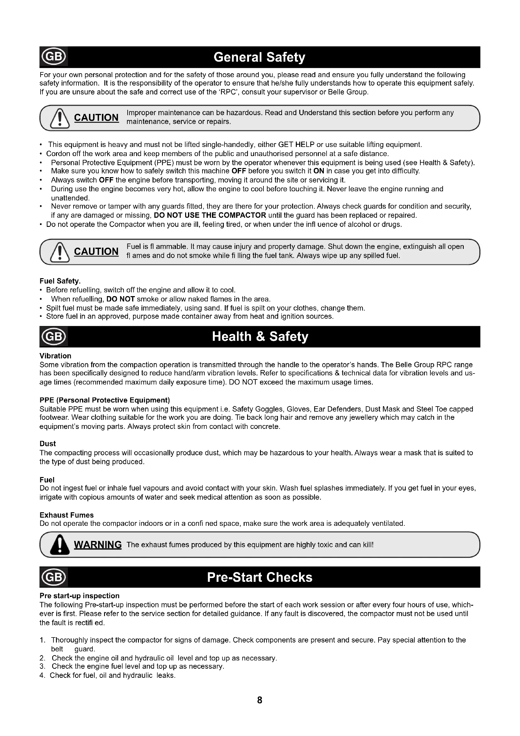
Honda Petrol Engine
- Open the fuel tap by moving the fuel ON / OFF lever fully to the right.
- If starting the engine from cold, set the choke ON by moving the choke lever fully to the left. If restarting a warm engine, the choke is usually not required, however, if the engine has cooled to a degree, partial choke may be required.
- Turn the engine ON / OFF switch clockwise to the 'I' position.
- Set the throttle to the idle position by moving the throttle lever fully to the right. Do not start the engine on full throttle, as the compactor will vibrate as soon as the engine starts.
- Taking a firm hold of the control handle with one hand, grasp the recoil starter handle with the other. Pull the recoil starter until engine resistance is felt, then let starter return.
- Taking care not to pull the starter's rope fully out, pull the starter handle briskly.
- Repeat until the engine fi res.
- Once the engine fires gradually set the choke lever to the OFF position by moving it to the right.
- If the engine fails to fire after several attempts, follow the troubleshooting guide.
- To stop the engine, set the throttle to idle and turn the engine ON / OFF switch anticlockwise to the '0' position.
- Turn the fuel off.
text_image
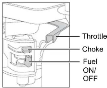
Throttle Choke Fuel ON/ OFFHatz Diesel Engine
- Turn ON the fuel by moving the fuel ON/OFF lever fully to the right.
- Set the engine speed control to start.
- Taking a firm hold of the control handle with one hand, grasp the recoil starter handle with the other. Pull the handle until engine resistance is felt, then let the starter return.
- Taking care not to pull the starter's rope fully out, pull the starter handle briskly with both hands.
- Repeat this procedure until the engine fi res.
- If the engine fails to start after several attempts, Follow the troubleshooting guide.
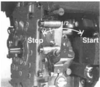
- To stop the engine, set the throttle control to idle, then press and hold the red stop button until the engine stops.

text_image
Stop 1/2 StartRobin EX 17 Petrol Engine
- Open the fuel cock.
- Turn the STOP SWITCH to the position 'I' (ON)
- Set the speed control lever 1/3 of the way towards the high speed position.
- Close the choke lever.
- If the engine is cold or the ambient temperature is low, close the choke lever fully.
- If the engine is warm or the ambient temperature is high, open the choke lever half way, or keep it fully open.
- Pull the starter handle slowly until resistance is felt. This is the 'compression' point. return the handle to its original position and pull swiftly. Do not pull out the ropeall the way. After starting the engine, allow the starter handle to return to its original position while still holding the handle.
- After starting the engine, gradually open the choke by turning the choke lever and finally keep it fully opened. Do not fully open the choke lever immediately when the engine is cold or the ambient temperature is low, because the engine may stop.
- To stop the engine, Set the speed control lever at the low speed position and allow the engine to run at low speed for 1 to 2 minutes before stopping.
- Turn the STOP SWITCH counter-clockwise to the position '0' (OFF)
- Close the fuel cock.
- Pull the starter handle slowly and return the handle to its original position when resistance is felt. This operation is necessary to prevent outside moist air from intruding into the combustion chamber.
Lombardini 15LD225 Diesel Engine
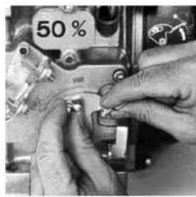
- Ensure the throttle control is at 50% of maximum speed (Halfway between MIN and MAX)
- Take a firm hold of the recoil starter handle and pull the rope softly until it is extended to it's full limit. Let the rope recoil completely. Start the engine by pulling strongly on the rope.
- Repeat this procedure until the engine fi res.
- If the engine fails to start after several attempts, consult the engine manual supplied with the machine.
- Leave the engine running at idle speed for 5 minutes.
CAUTION: During first 50 hours of use, do not exceed 70% of maximum rated power.
- To stop the engine, set the throttle control to the STOP position until the engine stops.

natural_image
Close-up of hands adjusting a mechanical component with a 50% mark (no visible text or symbols)
natural_image
Close-up of a hand using a tool to adjust or install a mechanical component (no visible text or symbols)
natural_image
Close-up of a hand using a tool to adjust or install a mechanical component (no visible text or symbols)
Operating Instructions
• Take the compactor to where it is required.
Where it is necessary to use lifting equipment to position the compactor, make sure the lifting equipment has a WLL (Working Load Limit) suitable for the compactors weight (see Technical Data section or the machine serial plate). Attach suitable chains or slings ONLY to the lifting point on the top of the compactor.
- Having carried out the checks listed in the 'Pre start' section, you may start the engine.
The Belle Group 'RPC' range of compactors are fitted with a centrifugal clutch, this allows the engine to run at idle without driving the gearbox.
As the engine speed is increased the clutch will engage and will drive the gearbox. For correct operation, the engine speed should be set to maximum.
- Set the throttle to maximum and use the control handle for direction and to steer or turn the compactor.
The control handle has been designed so that when it is being used in reverse and the operator lets go for any reason, the handle automatically moves into forward mode. This is a significant safety feature of the machine.
During normal operation you should not have to push the compactor but allow it to travel at its own pace.
The speed of travel will be determined by the condition of the surface being compacted.
Caution must be used when operating the compactor in reverse. Ensure that there are no obstructions or trip hazards when operating in reverse.
If the surface to be compacted is on a slope, great care must be taken when controlling the compactor's direction of travel. If necessary, use a suitable rope attached to the compactor at a low point on the chassis, to allow a helper to take part of the compactor's weight. Work up and down a slope not across.
• Work the compactor over the surface in an organised pattern until the required compaction has been achieved.
Where there are a number of different layers to be compacted on top of each other, compact each layer individually.
• To stop the compactor vibrating, set the throttle to idle. To stop the engine refer to the relevant start / stop procedure.
Trouble Shooting Guide
| Problem | Cause | Remedy |
| Engine will not start. No fuel. | Open fuel tap. | |
| Fill fuel tank. | ||
| Engine switched off. Switch | engine on. | |
| Spark plug fouled. Clean and reset plug gap. | ||
| Engine cold. Close choke. | ||
| Engine fl coded. Honda, open choke, fully open throttle, pull recoil starts until engin | ||
| Hatz, move speed control to stop, pull recoil starter 5 times then repeat start procedure. | ||
| Engine still will not start. Major Fault. Contact Agent or Belle Group. | ||
| Unit will not move. | Engine speed too slow. | Set engine speed control to fast. |
| Drive belt tension loose. | Adjust belt tension | |
| Air fi liter blocked. | Clean or renew air fi liter. | |
| Worn or Damaged Clutch. | Repair or Replace as necessary. | |
| Drive failure. | Contact Agent or Belle Group. | |
| Gearbox failure. | Contact Agent or Belle Group. | |
| Forward speed too slow. | Too much oil in hydraulic head. | Reduce oil level. |
| Wrong adjustment of control system | Contact Agent or Belle Group. | |
| Reverse speed too slow. | Not enough oil in hydraulic head. | Fill and bleed system. |
| Air in control system. | Bleed control system. | |
| Wrong adjustment of control system | Contact Agent or Belle Group. | |
| Loss of Hydraulic Oil. | Connectors leaking. | Reseal connectors. |
| Defective hydraulic hose. | Replace hose. | |
| Piston seal in gearbox defective. | Contact Agent or Belle Group. | |
| Machine operates erratically. | Shock mounts damaged. | Replace all four mounts. |
Service & Maintenance
The Belle Group 'RPC' range of Reversible Plate Compactors are designed to give many years of trouble free operation. It is, however, important that the simple regular maintenance listed in this section is carried out. It is recommended that an approved Belle Group dealer carries out all major maintenance and repairs. Always use genuine Belle Group replacement parts, the use of spurious parts may void your warranty.
Before any maintenance is carried out on the machine, switch off the engine. If working on a diesel engine, make sure that the stop switch is in the stop position.
Always set the compactor on level ground to ensure any fluid levels will be correctly read. Only use recommended oils (see chart on following page).
Running In Period
When the compactor is first used from new, the engine oil must be changed after the initial running in period (see engine manufacturer's manual for full detail). The belt tension should be checked after 4 hours use.
Drive Belt
Remove the belt guard then check the belt tension by placing light finger pressure on the top of the belt, as near central between the engine drive and gearbox pulley. The belt should deflect by approx. 10 to 15mm. If the belt tension requires adjustment, loosen the setscrew on the Belt Tensioning device and slide to the right. Once set, retighten the setscrew and check belt tension a second time. Finally, replace the belt guard ensuring it is correctly and securely fitted.
| Routine Maintenance Every 8 First month / 150 250 500 | hours | 50Hours | ||||
| Engine Oil Check Level | √ | |||||
| Change | √ | √ | ||||
| Air Filter | Check Condition/Clean | √ | ||||
| Replace when necessary / Every 12 months | ||||||
| Gearbox Oil | Change | √ | ||||
| Drive Belt | Tension | √ | √ | |||
Oil / Fuel Type & Quantity - Spark Plug Type
| Oil type | Quantity (Litre) | Fuel Type | Capacity (Litre) | Spark Plug Type | Electrode Gap (mm) | |
| Honda GX160 | S.A.E. 10W 30 | 0.6 | Unleaded | 3.6 | BM6ES or BPR6ES | 0.6 - 0.7 |
| Robin EX17 | S.A.E. 10W 30 | 1.1 | Unleaded | 3.6 | NGK BR-6HS | |
| Hatz 1B20-6 | S.A.E. 10W 30 | 0.9 | Diesel (BS2869) | Refer to Manual | N/A | N/A |
| Lombardini 15LD225 | S.A.E. 10W 30 | 0.8 | Diesel (BS2869) | 2.5 | N/A | N/A |
Oil Type & Quantity
| Component | Oil type | Honda | Robin | Hatz | Lombardini |
| Gearbox | S.A.E. 75W-90 | 0.6 Litres | 0.6 Litres | 0.6 Litres | 0.6 Litres |
| Hydraulic Control | Shell Tellus 32 | 0.2 Litres | 0.2 Litres | 0.2 Litres | 0.2 Litres |
| Fuchs Renolin MR520 | 0.2 Litres | 0.2 Litres | 0.2 Litres | 0.2 Litres |

CAUTION
WHILST RUNNING THIS MACHINE DURING THIS PROCEDURE, IT IS ADVISABLE TO PUT THE MACHINE ONTO A RUBBER MAT OR EQUIVALENT TO ABSORB SOME OF THE VIBRATION.
Bleeding the Hydraulic System
- Ensure the machine is in a stationary position, and situated on level ground.
- Remove the filler cap, and fill the control pump head with oil. Stop once you have reached the maximum level indicator, which is within the head.
- Slowly pump the control handle from the 'Forward Motion' position, to the 'Reverse Motion' position, until the oil level drops.
- Re-fill the control pump head up to the maximum level. Continue to pump the handle until resistance is felt, and the handle locks in the 'Reverse Motion' position.
- Again, re-fill the control pump head up to the maximum level.
- Re-fit the Filler Bung, and test the machine.
Service & Maintenance
Assembly of the Control Pump
- Carefully clean the housing with compressed air on the inside. Check for scratches on sliding bores for O Rings and there are no sharp edges.
- Press the Bushing in to Housing.
- Lubricate the Lip Seal with Hydraulic Oil and slip it on the Rack (open side away from the rack).
- Lubricate the Rack with Hydraulic Oil and slide it into the Housing until the Lip Seal is in the groove, making sure the teeth are in the right position. When the Lip Seal is in the Groove this represents forward motion.

CAUTION In reverse motion the Control Handles run parallel with the Housing in the direction of the operator.
- After lubricating the Pinion (without O Rings), insert it into the Housing and Rack. Check the movement of the Rack from Forward to Reverse. (See CAUTION).
6 Take the Pinion out and fi t the two O Rings, making sure they are not damaged. - Lubricate the Pinion and O Rings with hydraulic oil and carefully insert in to the Housing. Make sure the Rack is in the right position and this is easiest when in reverse motion.
- Fit the Shim and Retaining Ring. It may be necessary to push the Pinion from the opposite side to get them assembled.
- Place the Housing on the filler side and fit the O Rings to the bottom face. LOCTITE seal 518 is recommended.
- Assemble the Hydraulic Connector and Dowty Washer using LOCTITE 243.
- Assemble the Bracket and fi x with 4 screws and washers using LOCTITE 243.
- Loosely fit the Plug Screw and Washer DO NOT TIGHTEN.
Warranty

Your new Belle Group 'RPC' plate compactor is warranted to the original purchaser for a period of one-year (12 months) from the original date of purchase. The Belle Group warranty is against defects in design, materials and workmanship.
The following are not covered under the Belle Group warranty:
- Damage caused by abuse, misuse, dropping or other similar damage caused by or as a result of failure to follow assembly, operation or user maintenance instructions.
- Alterations, additions or repairs carried out by persons other than Belle Group or their recognised agents.
- Transportation or shipment costs to and from Belle Group or their recognised agents, for repair or assessment against a warranty claim, on any machine.
- Materials and/or labour costs to renew, repair or replace components due to fair wear and tear.
The following components are not covered by warranty.
- Drivebelt/s
- Engine Air Filter
- Engine Spark Plug
Belle Group and/or their recognised agents, directors, employees or insurers will not be held liable for consequential or other damages, losses or expenses in connection with or by reason of or the inability to use the machine for any purpose.
Warranty Claims
All warranty claims should firstly be directed to Belle Group or Belle Group Inc., either by telephone, by Fax, by E-mail, or in writing.
For Warranty claims:
Belle Group Warranty Department,
Sheen, Nr. Buxton
Derbyshire
SK17 0EU
England
Tel: +44 (0)1298 84606
Fax: +44 (0)1298 84722
Email : warranty@belle-group.co.uk
This manual has been written to help you operate and service the 'RPC' safely. This manual is intended for dealers and operators of the 'RPC'.
Foreword
The 'Machine Description' section helps you to familiarise yourself with the machine's layout and controls.
The 'Environment' section gives instructions on how to handle the recycling of discarded apparatus in an environmentally friendly way.
The ‘General Safety’ and ‘Health and Safety’ sections explain how to use the machine to ensure your safety and the safety of the general public.
The 'Start and Stop Procedure' helps you with starting and stopping the machine.
The 'Trouble Shooting Guide' helps you if you have a problem with your machine.
The 'Service & Maintenance' section is to help you with the general maintenance and servicing of your machine.
The 'Warranty' Section details the nature of the warranty cover and the claims procedure.
The ‘Declaration of conformity’ section shows the standards that the machine has been built to.
Directives with regard to the notations.
Text in this manual to which special attention must be paid are shown in the following way:

CAUTION
The product can be at risk. The machine or yourself can be damaged or injured if procedures are not carried out in the correct way.

WARNING
The life of the operator can be at risk.

WARNING

WARNING
Before you operate or carry out any maintenance on this machine YOU MUST READ and STUDY this manual.
KNOW how to safely use the unit's controls and what you must do for safe maintenance. (NB Be sure that you know how to switch the machine off before you switch on, in case you get into diffi culty.)
ALWAYS wear or use the proper safety items required for your personal protection. If you have ANY QUESTIONS about the safe use or maintenance of this unit, ASK YOUR SUPERVISOR OR CONTACT: BELLE GROUP (UK): +44 (0) 1298 84606

Contents
How To Use This Manual....14
Warning 14
Machine Description....15
Technical Data....15
Environment 15
General Safety 16
Health and Safety....16
Pre-Start Checks....16
Reasons For Compaction....17
Start and Stop Procedure....17 - 18
Operating Instructions 18
Trouble Shooting Guide 19
Service & Maintenance 19 - 21
Warranty 21

text_image
1 2 3 4 5 6 7 8 A B C- Throttle lever.
- Recoil Starter Handle.
- Fuel Tank.
- Lifting Point.
- Handle Release Catch.
- Forward / Reverse Control Handle.
- Main Handle.
- Belt Guard.
Technical Data

| Model | 30/40 | |
| A - Plate Width in | 15.7 | |
| B - Height in | 49.8 | |
| C - Length in | 25.9 | 25.9 |
| Engine - Honda Petrol (Hp) | GX160 (5.5) | |
| Engine - Robin Petrol (Hp) | EX17 (6) | |
| Engine - Hatz Diesel (Hp) | 1B20-6 (4.2) | |
| Engine - Lombardini Diesel (Hp) | 15LD225 (4) | |
| Weight - Honda Petrol lbs | 339.5 | 410 |
| Weight - Robin Petrol lbs 339.5 | 410 | |
| Weight - Hatz Diesel lbs | 385.8 | 441 |
| Weight - Lombardini Diesel lbs | 376.9 | 440.9 |
| Centrifugal Force kN | 30 | 30 |
| Frequency Hz | 90 | 90 |
| Engine RPM - Honda | 3400 | 3400 |
| Engine RPM - Robin | 3600 | 3600 |
| Engine RPM - Hatz | 3000 | 3000 |
| Engine RPM - Lombardini | 3000 | 3000 |
| Maximum Travel Speed ft/min | >75.5 | >75.5 |
| Sound Power (dB(A)) | 108 | 108 |
49.8
* Minimum level to En500 Part 4
Environment


Safe Disposal.
Instructions for the protection of the environment. The machine contains valuable materials. Take the discarded apparatus and accessories to the relevant recycling facilities.
| Component | Material |
| Handle | Steel |
| Front cover HDPE | |
| Main frame Steel | |
| Baseplate | Steel |
| Hand Grips Polyurethane Foam | |
| Engine Aluminium | |
| Flexible Mounts Steel and Rubber | |
| Various Parts Steel and Aluminium |
For your own personal protection and for the safety of those around you, please read and ensure you fully understand the following safety information. It is the responsibility of the operator to ensure that he/she fully understands how to operate this equipment safely. If you are unsure about the safe and correct use of the 'RPC', consult your supervisor or Belle Group.

CAUTION
Improper maintenance can be hazardous. Read and Understand this section before you perform any maintenance, service or repairs.
- This equipment is heavy and must not be lifted single-handedly, either GET HELP or use suitable lifting equipment.
- Cordon off the work area and keep members of the public and unauthorised personnel at a safe distance.
• Personal Protective Equipment (PPE) must be worn by the operator whenever this equipment is being used (see Health & Safety).
• Make sure you know how to safely switch this machine OFF before you switch it ON in case you get into difficulty.
• Always switch OFF the engine before transporting, moving it around the site or servicing it. - During use the engine becomes very hot, allow the engine to cool before touching it. Never leave the engine running and unattended.
- Never remove or tamper with any guards fitted, they are there for your protection. Always check guards for condition and security, if any are damaged or missing, DO NOT USE THE COMPACTOR until the guard has been replaced or repaired.
- Do not operate the Compactor when you are ill, feeling tired, or when under the influence of alcohol or drugs.

CAUTION
Fuel is fl ammable. It may cause injury and property damage. Shut down the engine, extinguish all open fl ames and do not smoke while fi lling the fuel tank. Always wipe up any spilled fuel.
Fuel Safety.
- Before refuelling, switch off the engine and allow it to cool.
- When refuelling, DO NOT smoke or allow naked flames in the area.
- Spilt fuel must be made safe immediately, using sand. If fuel is spilt on your clothes, change them.
- Store fuel in an approved, purpose made container away from heat and ignition sources.

Health & Safety
Vibration
Some vibration from the compaction operation is transmitted through the handle to the operator's hands. The Belle Group RPC range has been specifically designed to reduce hand/arm vibration levels. Refer to specifications & technical data for vibration levels and usage times (recommended maximum daily exposure time). DO NOT exceed the maximum usage times.
PPE (Personal Protective Equipment)
Suitable PPE must be worn when using this equipment i.e. Safety Goggles, Gloves, Ear Defenders, Dust Mask and Steel Toe capped footwear. Wear clothing suitable for the work you are doing. Tie back long hair and remove any jewellery which may catch in the equipment's moving parts. Always protect skin from contact with concrete.
Dust
The compacting process will occasionally produce dust, which may be hazardous to your health. Always wear a mask that is suited to the type of dust being produced.
Fuel
Do not ingest fuel or inhale fuel vapours and avoid contact with your skin. Wash fuel splashes immediately. If you get fuel in your eyes, irrigate with copious amounts of water and seek medical attention as soon as possible.
Exhaust Fumes
Do not operate the compactor indoors or in a confined space, make sure the work area is adequately ventilated.

WARNING
The exhaust fumes produced by this equipment are highly toxic and can kill!

Health & Safety
Pre start-up inspection
The following Pre-start-up inspection must be performed before the start of each work session or after every four hours of use, whichever is first. Please refer to the service section for detailed guidance. If any fault is discovered, the compactor must not be used until the fault is rectified.
- Thoroughly inspect the compactor for signs of damage. Check components are present and secure. Pay special attention to the belt guard.
- Check the engine oil and hydraulic oil level and top up as necessary.
- Check the engine fuel level and top up as necessary.
- Check for fuel, oil and hydraulic leaks.
Reasons For Compaction
Soil, which has been disturbed or new infill, subbase and blacktop, will have small voids or air pockets which, if not compacted, will lead to one or more problems occurring.
- As traffic crosses the surface of an uncompacted area, the material is compressed. This leads to subsidence of the top surface as the material fills the voids.
- A similar situation occurs with static loads on uncompacted ground. The load (e.g. a building) will sink.
- Materials with voids are more susceptible to water seepage, leading to erosion. Water ingress may also cause the soil to expand during freezing temperatures and contract during dry spells. Expansion and contraction is a major cause of damage to building foundations and normally leads to the structure requiring underpinning.
Compaction increases the density of the material and therefore increases its load bearing capacity. Reduces air voids and therefore reduces the risk of subsidence, expansion and contraction, due to ingress of water.
Start And Stop Procedure

Honda GX160 Gasoline Engine
- Open the fuel tap by moving the fuel ON / OFF lever fully to the right.
- If starting the engine from cold, set the choke ON by moving the choke lever fully to the left. If restarting a warm engine, the choke is usually not required, however, if the engine has cooled to a degree, partial choke may be required.
- Turn the engine ON / OFF switch clockwise to the 'I' position.
- Set the throttle to the idle position by moving the throttle lever fully to the right. Do not start the engine on full throttle, as the compactor will vibrate as soon as the engine starts.
-
Taking a firm hold of the control handle with one hand, grasp the recoil starter handle with the other. Pull the recoil starter until engine resistance is felt, then let starter return.
-
Taking care not to pull the starter's rope fully out, pull the starter handle briskly.
-
Repeat until the engine fi res.
-
Once the engine fires gradually set the choke lever to the OFF position by moving it to the right.
-
If the engine fails to fire after several attempts, follow the troubleshooting guide.
-
To stop the engine, set the throttle to idle and turn the engine ON / OFF switch anticlockwise to the '0' position.
-
Turn the fuel off.

text_image
Throttle Choke Fuel ON/ OFFHatz Diesel Engine
- Turn ON the fuel by moving the fuel ON/OFF lever fully to the right.
- Set the engine speed control to start.
- Taking a fi rm hold of the control handle with one hand, grasp the recoil starter handle with the other. Pull the handle until engine resistance is felt, then let the starter return.
- Taking care not to pull the starter's rope fully out, pull the starter handle briskly with both hands.
- Repeat this procedure until the engine fi res.
- If the engine fails to start after several attempts, Follow the troubleshooting guide.
- To stop the engine, set the throttle control to idle, then press and hold the red stop button until the engine stops.
text_image
Stop 1/2 StartRobin EX 17 Gasoline Engine
- Open the fuel cock.
- Turn the STOP SWITCH to the position 'I' (ON)
- Set the speed control lever 1/3 of the way towards the high speed position.
- Close the choke lever.
- If the engine is cold or the ambient temperature is low, close the choke lever fully.
- If the engine is warm or the ambient temperature is high, open the choke lever half way, or keep it fully open.
- Pull the starter handle slowly until resistance is felt. This is the 'compression' point. return the handle to its original position and pull swiftly. Do not pull out the ropeall the way. After starting the engine, allow the starter handle to return to its original position while still holding the handle.
- After starting the engine, gradually open the choke by turning the choke lever and finally keep it fully opened. Do not fully open the choke lever immediately when the engine is cold or the ambient temperature is low, because the engine may stop.
- To stop the engine, Set the speed control lever at the low speed position and allow the engine to run at low speed for 1 to 2 minutes before stopping.
- Turn the STOP SWITCH counter-clockwise to the position '0' (OFF)
- Close the fuel cock.
- Pull the starter handle slowly and return the handle to its original position when resistance is felt. This operation is necessary to prevent outside moist air from intruding into the combustion chamber.
Lombardini 15LD225 Diesel Engine
- Ensure the throttle control is at 50% of maximum speed (Halfway between MIN and MAX)
- Take a firm hold of the recoil starter handle and pull the rope softly until it is extended to it's full limit. Let the rope recoil completely. Start the engine by pulling strongly on the rope.
- Repeat this procedure until the engine fi res.
- If the engine fails to start after several attempts, consult the engine manual supplied with the machine.
- Leave the engine running at idle speed for 5 minutes.
CAUTION: During first 50 hours of use, do not exceed 70% of maximum rated power.
- To stop the engine, set the throttle control to the STOP position until the engine stops.

natural_image
Close-up of hands adjusting a mechanical component with a 50% label (no readable text or symbols beyond the label)
natural_image
Close-up of a hand using a tool to adjust or install a mechanical component (no visible text or symbols)
natural_image
Close-up of a hand using a power tool to adjust or install a component (no visible text or symbols)
Operating Instructions
• Take the compactor to where it is required.
Where it is necessary to use lifting equipment to position the compactor, make sure the lifting equipment has a WLL (Working Load Limit) suitable for the compactors weight (see Technical Data section or the machine serial plate). Attach suitable chains or slings ONLY to the lifting point on the top of the compactor.
- Having carried out the checks listed in the 'Pre start' section, you may start the engine.
The Belle Group 'RPC' range of compactors are fitted with a centrifugal clutch, this allows the engine to run at idle without driving the gearbox.
As the engine speed is increased the clutch will engage and will drive the gearbox. For correct operation, the engine speed should be set to maximum.
- Set the throttle to maximum and use the control handle for direction and to steer or turn the compactor.
The control handle has been designed so that when it is being used in reverse and the operator lets go for any reason, the handle automatically moves into forward mode. This is a significant safety feature of the machine.
During normal operation you should not have to push the compactor but allow it to travel at its own pace.
The speed of travel will be determined by the condition of the surface being compacted.
Caution must be used when operating the compactor in reverse. Ensure that there are no obstructions or trip hazards when operating in reverse.
If the surface to be compacted is on a slope, great care must be taken when controlling the compactor's direction of travel. If necessary, use a suitable rope attached to the compactor at a low point on the chassis, to allow a helper to take part of the compactor's weight. Work up and down a slope not across.
• Work the compactor over the surface in an organised pattern until the required compaction has been achieved.
Where there are a number of different layers to be compacted on top of each other, compact each layer individually.
• To stop the compactor vibrating, set the throttle to idle. To stop the engine refer to the relevant start / stop procedure.
Trouble Shooting Guide
| Problem | Cause | Remedy |
| Engine will not start. No fuel. | Open fuel tap. | |
| Fill fuel tank. | ||
| Engine switched off. Switch | engine on. | |
| Spark plug fouled. Clean and reset plug gap. | ||
| Engine cold. Close choke. | ||
| Engine fl coded. Honda, open choke, fully open throttle, pull recoil starts until engin | ||
| Hatz, move speed control to stop, pull recoil starter 5 times then repeat start procedure. | ||
| Engine still will not start. Major Fault. Contact Agent or Belle Group. | ||
| Unit will not move. | Engine speed too slow. | Set engine speed control to fast. |
| Drive belt tension loose. | Adjust belt tension | |
| Air fi liter blocked. | Clean or renew air fi liter. | |
| Worn or Damaged Clutch. | Repair or Replace as necessary. | |
| Drive failure. | Contact Agent or Belle Group. | |
| Gearbox failure. | Contact Agent or Belle Group. | |
| Forward speed too slow. | Too much oil in hydraulic head. | Reduce oil level. |
| Wrong adjustment of control system | Contact Agent or Belle Group. | |
| Reverse speed too slow. | Not enough oil in hydraulic head. | Fill and bleed system. |
| Air in control system. | Bleed control system. | |
| Wrong adjustment of control system | Contact Agent or Belle Group. | |
| Loss of Hydraulic Oil. | Connectors leaking. | Reseal connectors. |
| Defective hydraulic hose. | Replace hose. | |
| Piston seal in gearbox defective. | Contact Agent or Belle Group. | |
| Machine operates erratically. | Shock mounts damaged. | Replace all four mounts. |
Service & Maintenance

The Belle Group 'RPC' range of Reversible Plate Compactors are designed to give many years of trouble free operation. It is, however, important that the simple regular maintenance listed in this section is carried out. It is recommended that an approved Belle Group dealer carries out all major maintenance and repairs. Always use genuine Belle Group replacement parts, the use of spurious parts may void your warranty.
Before any maintenance is carried out on the machine, switch off the engine. If working on a diesel engine, make sure that the stop switch is in the stop position.
Always set the compactor on level ground to ensure any fluid levels will be correctly read. Only use recommended oils (see chart on following page).
Running In Period
When the compactor is first used from new, the engine oil must be changed after the initial running in period (see engine manufacturer's manual for full detail). The belt tension should be checked after 4 hours use.
Drive Belt
Remove the belt guard then check the belt tension by placing light finger pressure on the top of the belt, as near central between the engine drive and gearbox pulley. The belt should deflect by approx. 10 to 15mm. If the belt tension requires adjustment, loosen the setscrew on the Belt Tensioning device and slide to the right. Once set, retighten the setscrew and check belt tension a second time. Finally, replace the belt guard ensuring it is correctly and securely fitted.
| Routine Maintenance Every 8 First month / 150 250 500 | hours | 50Hours | ||||
| Engine Oil Check Level | √ | |||||
| Change | √ | √ | ||||
| Air Filter | Check Condition/Clean | √ | ||||
| Replace when necessary / Every 12 months | ||||||
| Gearbox Oil | Change | √ | ||||
| Drive Belt | Tension | √ | √ | |||
Oil / Fuel Type & Quantity - Spark Plug Type
| Oil type | Quantity (Pints) | Fuel Type | Capacity (Pints) | Spark Plug Type | Electrode Gap (in) | |
| Honda GX160 | S.A.E. 10W 30 | 1.3 | Unleaded | 7.6 | BM6ES or BPR6ES | 0.02 - 0.03 |
| Robin EX17 | S.A.E. 10W 30 | 2.3 | Unleaded | 7.6 | NGK BR-6HS | |
| Hatz 1B20-6 | S.A.E. 10W 30 | 1.9 | Diesel (BS2869) | Refer to Manual | N/A | N/A |
| Lombardini 15LD225 | S.A.E. 10W 30 | 1.7 | Diesel (BS2869) | 5.3 | N/A | N/A |
Oil Type & Quantity
| Component | Oil type | Honda | Robin | Hatz | Lombardini |
| Gearbox | S.A.E. 75W-90 | 1.3 Pints | 1.3 Pints | 1.3 Pints | 1.3 Pints |
| Hydraulic Control | Shell Tellus 32 | 0.4 Pints | 0.4 Pints | 0.4 Pints | 0.4 Pints |
| Fuchs Renolin MR520 | 0.4 Pints | 0.4 Pints | 0.4 Pints | 0.4 Pints |

CAUTION
WHILST RUNNING THIS MACHINE DURING THIS PROCEDURE, IT IS ADVISABLE TO PUT THE MACHINE ONTO A RUBBER MAT OR EQUIVALENT TO ABSORB SOME OF THE VIBRATION.
Bleeding the Hydraulic System
- Ensure the machine is in a stationary position, and situated on level ground.
- Remove the filler cap, and fill the control pump head with oil. Stop once you have reached the maximum level indicator, which is within the head.
- Slowly pump the control handle from the 'Forward Motion' position, to the 'Reverse Motion' position, until the oil level drops.
- Re-fill the control pump head up to the maximum level. Continue to pump the handle until resistance is felt, and the handle locks in the 'Reverse Motion' position.
- Again, re-fill the control pump head up to the maximum level.
- Re-fit the Filler Bung, and test the machine.
Service & Maintenance
Assembly of the Control Pump
- Carefully clean the housing with compressed air on the inside. Check for scratches on sliding bores for O Rings and there are no sharp edges.
- Press the Bushing in to Housing.
- Lubricate the Lip Seal with Hydraulic Oil and slip it on the Rack (open side away from the rack).
- Lubricate the Rack with Hydraulic Oil and slide it into the Housing until the Lip Seal is in the groove, making sure the teeth are in the right position. When the Lip Seal is in the Groove this represents forward motion.

CAUTION
In reverse motion the Control Handles run parallel with the Housing in the direction of the operator.
- After lubricating the Pinion (without O Rings), insert it into the Housing and Rack. Check the movement of the Rack from Forward to Reverse. (See CAUTION).
6 Take the Pinion out and fit the two O Rings, making sure they are not damaged. - Lubricate the Pinion and O Rings with hydraulic oil and carefully insert in to the Housing. Make sure the Rack is in the right position and this is easiest when in reverse motion.
- Fit the Shim and Retaining Ring. It may be necessary to push the Pinion from the opposite side to get them assembled.
- Place the Housing on the filler side and fit the O Rings to the bottom face. LOCTITE seal 518 is recommended.
- Assemble the Hydraulic Connector and Dowty Washer using LOCTITE 243.
- Assemble the Bracket and fix with 4 screws and washers using LOCTITE 243.
- Loosely fit the Plug Screw and Washer DO NOT TIGHTEN.
Warranty

Your new Belle Group 'RPC' plate compactor is warranted to the original purchaser for a period of one-year (12 months) from the original date of purchase. The Belle Group warranty is against defects in design, materials and workmanship.
The following are not covered under the Belle Group warranty:
- Damage caused by abuse, misuse, dropping or other similar damage caused by or as a result of failure to follow assembly, operation or user maintenance instructions.
- Alterations, additions or repairs carried out by persons other than Belle Group or their recognised agents.
- Transportation or shipment costs to and from Belle Group or their recognised agents, for repair or assessment against a warranty claim, on any machine.
- Materials and/or labour costs to renew, repair or replace components due to fair wear and tear.
The following components are not covered by warranty.
- Drivebelt/s
- Engine Air Filter
- Engine Spark Plug
Belle Group and/or their recognised agents, directors, employees or insurers will not be held liable for consequential or other damages, losses or expenses in connection with or by reason of or the inability to use the machine for any purpose.
Warranty Claims
All warranty claims should firstly be directed to Belle Group or Belle Group Inc., either by telephone, by Fax, by E-mail, or in writing.
For Warranty claims:
Belle Group Inc.
3959 Electric Road, Roanoke
VA, 24018
USA
Tel: +1 540.345.5090
Fax: +1 540.345.5091
E-mail: Bellegroupinc@aol.com
natural_image
Close-up of hands adjusting a mechanical component with a 50% label (no readable text or symbols beyond the label)
natural_image
Close-up of a hand using a tool to adjust or install a mechanical component (no visible text or symbols)
natural_image
Close-up of a hand operating a mechanical switch or tool (no visible text or symbols)
Utilisation
Belle Group Warranty Department,
Sheen, Nr. Buxton
Derbyshire
SK17 0EU
Angleterre
Tel: +44 (0)1298 84606
Fax: +44 (0)1298 84722
Email : warranty@belle-group.co.uk

Uso de este manual
natural_image
Close-up of hands adjusting a mechanical component with a 50% label (no readable text or symbols beyond the label)
natural_image
Close-up of a hand using a tool to adjust or install a mechanical component (no visible text or symbols)
natural_image
Close-up of a hand using a tool to adjust or install a mechanical component (no visible text or symbols)E
Belle Group Warranty Department,
Sheen, Nr. Buxton
Derbyshire
SK17 0EU
England
Tel: +44 (0)1298 84606
Fax: +44 (0)1298 84722
Email : warranty@belle-group.co.uk
natural_image
Technical line drawing of a mechanical component with no visible text or symbolsEstrangulador
Crontrolo da Mistura Alavanca Ligado/ Desligado de Combustivel
Motor Hatz Gasóleo
natural_image
Close-up of a hand using a tool to adjust or install a mechanical component (no visible text or symbols)
natural_image
Close-up of a hand using a power tool to adjust or install a mechanical component (no visible text or symbols)P
Belle Group Warranty Department,
Sheen, Nr. Buxton
Derbyshire
SK17 0EU
England
Tel: +44 (0)1298 84606
Fax: +44 (0)1298 84722
Email : warranty@belle-group.co.uk
Robin EX17 Benzine motor.
natural_image
Close-up of hands adjusting a mechanical component with a 50% label (no readable text or symbols beyond the number)
natural_image
Close-up of a hand adjusting a mechanical component with no visible text or symbols
natural_image
Close-up of a hand using a tool to adjust or install a mechanical component (no visible text or symbols)Belle Group Warranty Department,
Sheen, Nr. Buxton
Derbyshire
SK17 0EU
England
Tel: +44 (0)1298 84606
Fax: +44 (0)1298 84722
Email : warranty@belle-group.co.uk
natural_image
Close-up of hands adjusting a mechanical component with a 50% label (no readable text or symbols beyond the label)
natural_image
Close-up of a hand using a tool to adjust or install a mechanical component (no visible text or symbols)
natural_image
Close-up of a hand operating a mechanical switch or tool (no visible text or symbols)
Belle Group Warranty Department,
Sheen, Nr. Buxton
Derbyshire
SK17 0EU
England
Tel: +44 (0)1298 84606
Fax: +44 (0)1298 84722
Email : warranty@belle-group.co.uk
Robin EX13 & EX17 Ottomotor
natural_image
Close-up of hands adjusting a mechanical component with a 50% label (no readable text or symbols beyond the label)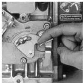
natural_image
Close-up of a hand using a wrench to adjust a mechanical component (no visible text or symbols)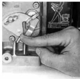
natural_image
Close-up of a hand using a tool to adjust or install a mechanical component (no visible text or symbols)
Bedienung Des Rüttlers
Belle Group Warranty Department,
Sheen, Nr. Buxton
Derbyshire
SK17 0EU
England
Tel: +44 (0)1298 84606
Fax: +44 (0)1298 84722
Email : warranty@belle-group.co.uk

natural_image
Close-up of hands adjusting a mechanical component with a 50% label (no readable text or symbols beyond the label)
natural_image
Close-up of a hand using a wrench to adjust a mechanical component (no visible text or symbols)
natural_image
Close-up of a hand using a tool to adjust or install a mechanical component (no visible text or symbols)
Belle Group Warranty Department,
Sheen, Nr. Buxton
Derbyshire
SK17 0EU
England
Email : warranty@belle-group.co.uk

natural_image
Close-up of hands adjusting a mechanical component with a 50% mark and scale (no readable text or symbols)
natural_image
Close-up of a hand using a tool to adjust or install a mechanical component (no visible text or symbols)
natural_image
Close-up of a hand using a tool to adjust or install a mechanical component (no visible text or symbols)S
Driftinstruktioner
Belle Group Warranty Department,
Sheen, Nr. Buxton
Derbyshire
SK17 0EU
England
Tel: +44 (0)1298 84606
Fax: +44 (0)1298 84722
Email : warranty@belle-group.co.uk
* Minimum level to En500 Part 4
Miljø


Trygt avfall
natural_image
Close-up of hands adjusting a mechanical component with a 50% label (no readable text or symbols beyond the label)
natural_image
Close-up of a hand using a tool to adjust or install a mechanical component (no visible text or symbols)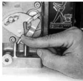
natural_image
Close-up of a hand operating a mechanical device with no visible text or symbols
Bruksanvisning
Belle Group Warranty Department,
Sheen, Nr. Buxton
Derbyshire
SK17 0EU
England
Tel: +44 (0)1298 84606
Fax: +44 (0)1298 84722
Email : warranty@belle-group.co.uk3
natural_image
Close-up of hands adjusting a mechanical component with a 50% label (no readable text or symbols beyond the label)
natural_image
Close-up of a hand using a tool to adjust or install a mechanical component (no visible text or symbols)
natural_image
Close-up of a hand using a tool to adjust or install a mechanical component (no visible text or symbols)
Toimintaohjeet
Belle Group Warranty Department,
Sheen, Nr. Buxton
Derbyshire
SK17 0EU
England
Tel: +44 (0)1298 84606
Fax: +44 (0)1298 84722
Email : warranty@belle-group.co.uk
Procedura Start i Stop

- Ensure the throttle control is at 50% of maximum speed (Halfway between MIN and MAX)
- Take a firm hold of the recoil starter handle and pull the rope softly until it is extended to it's full limit. Let the rope recoil completely. Start the engine by pulling strongly on the rope.
- Repeat this procedure until the engine fi res.
- If the engine fails to start after several attempts, consult the engine manual supplied with the mach
- Leave the engine running at idle speed for 5 minutes.
CAUTION: During first 50 hours of use, do not exceed 70% of maximum rated power.
- To stop the engine, set the throttle control to the STOP position until the engine stops.

natural_image
Close-up of hands adjusting a mechanical component with a 50% label (no readable text or symbols beyond the label)
natural_image
Close-up of a hand using a tool to adjust or install a mechanical component (no visible text or symbols)
natural_image
Close-up of a hand using a tool to adjust or install a small electronic component (no visible text or symbols)
Praca Ubijarki
Belle Group Warranty Department,
Sheen, Nr. Buxton
Derbyshire
SK17 0EU
England
Tel: +44 (0)1298 84606
Fax: +44 (0)1298 84722
Email : warranty@belle-group.co.uk3
text_image
Technical diagram of a mechanical device with numbered components labeled 1, 2, 3, and 4.
text_image
7 6 5 A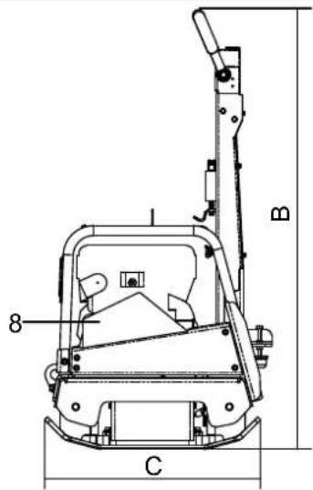
text_image
B 8 CBelle Group Warranty Department,
Sheen, Nr. Buxton
Derbyshire
SK17 0EU
Англия
natural_image
Close-up of hands adjusting a mechanical component with a 50% label (no readable text or symbols beyond the label)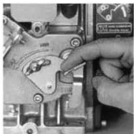
natural_image
Close-up of a hand using a tool to adjust or install a mechanical component (no visible text or symbols)
natural_image
Close-up of a hand operating a mechanical switch or tool (no visible text or symbols)
Töötamisjuhised
Belle Group Warranty Department,
Sheen, Nr. Buxton
Derbyshire
SK17 0EU
England
Tel: +44 (0)1298 84606
Fax: +44 (0)1298 84722
Email : warranty@belle-group.co.uk
natural_image
Close-up of hands adjusting a mechanical component with a 50% label (no readable text or symbols beyond the label)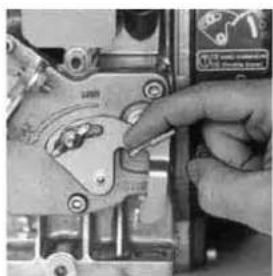
natural_image
Close-up of a hand using a tool to adjust or install a mechanical component (no visible text or symbols)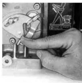
natural_image
Close-up of a hand adjusting a mechanical component with no visible text or symbolsLV
Belle Group Warranty Department,
Sheen, Nr. Buxton
Derbyshire
SK17 0EU
England
Tel: +44 (0)1298 84606
Fax: +44 (0)1298 84722
Email : warranty@belle-group.co.uk
natural_image
Close-up of hands adjusting a mechanical component with a 50% label (no readable text or symbols beyond the label)
natural_image
Close-up of a hand using a tool to adjust or install a mechanical component (no visible text or symbols)
natural_image
Close-up of a hand using a tool to adjust or install a mechanical component (no visible text or symbols)LT
Email : warranty@belle-group.co.uk
text_image
Technical diagram of a mechanical device with numbered parts labeled 1 to 4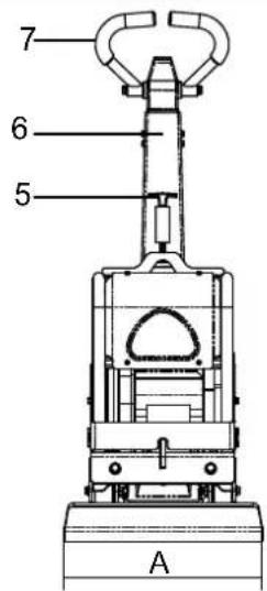
text_image
7 6 5 A
text_image
B 8 Cnatural_image
Technical line drawing of a mechanical component with no visible text or symbolsnatural_image
Close-up of hands adjusting a mechanical component with a 50% label (no readable text or symbols beyond the number)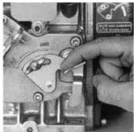
natural_image
Close-up of hands using a manual tool to adjust or install a mechanical component (no visible text or symbols)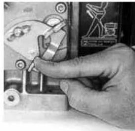
natural_image
Close-up of a hand operating a mechanical switch or tool (no visible text or symbols)BG
Експлоатация
• Местене
Belle Group Warranty Department,
Sheen, Nr. Buxton
Derbyshire
SK17 0EU
England
Tel: +44 (0)1298 84606
Fax: +44 (0)1298 84722
Email : warranty@belle-group.co.uk
- Ensure the throttle control is at 50% of maximum speed (Halfway between MIN and MAX)
- Take a firm hold of the recoil starter handle and pull the rope softly until it is extended to it's full limit. Let the rope recoil completely. Start the engine by pulling strongly on the rope.
- Repeat this procedure until the engine fi res.
- If the engine fails to start after several attempts, consult the engine manual supplied with the machine.
- Leave the engine running at idle speed for 5 minutes.
CAUTION: During first 50 hours of use, do not exceed 70% of maximum rated power.
- To stop the engine, set the throttle control to the STOP position until the engine stops.
natural_image
Close-up of hands adjusting a mechanical component with a 50% label (no readable text or symbols beyond the label)
natural_image
Close-up of a hand using a wrench to adjust a mechanical component (no visible text or symbols)
natural_image
Close-up of a hand adjusting a mechanical component with a tool (no visible text or symbols)
Obsluha zařízení
Belle Group Warranty Department,
Sheen, Nr. Buxton
Derbyshire
SK17 0EU
England
Tel: +44 (0)1298 84606
Fax: +44 (0)1298 84722
Email : warranty@belle-group.co.uk
natural_image
Close-up of hands adjusting a mechanical component with a 50% label (no readable text or symbols beyond the label)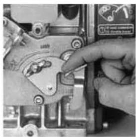
natural_image
Close-up of a hand adjusting a mechanical component with a tool (no visible text or symbols)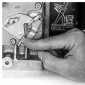
natural_image
Close-up of a hand using a tool to adjust or install a mechanical component (no visible text or symbols)
- Ensure the machine is in a stationary position, and situated on level ground.
- Remove the filler cap, and fill the control pump head with oil. Stop once you have reached the maximum level indicator, which is within the head.
- Slowly pump the control handle from the 'Forward Motion' position, to the 'Reverse Motion' position, until the oil level drops.
- Re-fill the control pump head upto the maximum level. Continue to pump the handle until resistance is felt, and the handle locks in the 'Reverse Motion' position.
- Again, re-fi II the control pump head upto the maximum level.
- Re-fi t the Filler Bung, and test the machine.
Belle Group Warranty Department,
Sheen, Nr. Buxton
Derbyshire
SK17 0EU
England
Tel: +44 (0)1298 84606
Fax: +44 (0)1298 84722
Email : warranty@belle-group.co.uk
* Minimum level to En500 Part 4
Környezet


natural_image
Close-up of hands adjusting a mechanical component with a 50% mark (no visible text or symbols)
natural_image
Close-up of a hand using a tool to adjust or install a mechanical component (no visible text or symbols)
natural_image
Close-up of a hand using a tool to adjust or install a mechanical component (no visible text or symbols)Belle Group Warranty Department,
Sheen, Nr. Buxton
Derbyshire
SK17 0EU
England
Email : warranty@belle-group.co.uk
natural_image
Close-up of a hand using a tool to adjust or install a mechanical component (no visible text or symbols)
natural_image
Close-up of a hand using a power tool on an electrical switch (no visible text or symbols)
Upute za rad
- Postavljanje vibro ploče na mjesto rada.
Kada je neophodno koritisti opremu za podizanje vibro ploče, provjerie da li oprema za podizanje ima nosivost odgovarjuću težini vibro ploče (vidi odjeljak Tehnički podaci ili pločicu sa serijskim podacima stroja). Prikvačite odgovarajući lanac ili uže ISKLJUČIVO na točku za podizanje na vrhu vibro ploče.
- Kada ste izvršili pregled opisan u odjeljku „provjere prije startanja“, možete startati motor.
U asortiman RPC vibro ploča tvrtke Belle Group ugrađeno je centrifugalno kvačilo, što omogućuje da radi u praznom hodu bez pokretanja mehanizma radilice. Kako se brzina motora povećava kvačilo će se uključiti i motor će pokrenuti mehanizam radilice. Za ispravan rad, brzina rada motora treba biti podešena na maksimum.
Belle Group Warranty Department,
Sheen, Nr. Buxton
Derbyshire
SK17 0EU
England
Tel: +44 (0)1298 84606
Fax: +44 (0)1298 84722
Email : warranty@belle-group.co.uk
www.Belle247.com
Belle Group Replacement Parts
are now available for purchase online...
24 Hours a Day, 7 Days a Week!

text_image
Belle Customer SERVICE Catalog - Box - Pocket Serial - Open system instructions here Categories: Vehicle records orders; Specific types: Options; Feedback key memory: Admin Quick Links: New Machines Click here to purchase a new headache. Spare Parts Click here to purchase spare parts. Place Order Click here to place an order. View Media Click here to save media Customer Belle GROUP Welcome: Welcome mark server : You left logged-in 37.24 on 62.87.2007. Favorite Record Feedback for Technical Support Feeling : (27.04.2007) Price List Update The price is the UK Trading : (24.04.2007) Marks Text Message This is a fact of the New : (25.12.2007) Text Message & Message ** Now Buy Safe Store Customer Information Services Belle Group Belle Group Belle Group Belle Group Belle Group Belle Group Belle Group Belle Group Belle Group Belle Group Belle Group Belle Group Belle Group Belle Group Belle Group Belle Group Belle Group Belle Group Belle Group Belle Group Belle Group Belle Group Belle Group Belle Group Belle Group Belle GROUPE Belle GROUPE Belle GROUPE Belle GROUPE Belle GROUPE Belle GROUPE Belle GROUPE Belle GROUPE Belle GROUPE Belle GROUPE Belle GROUPE Belle GROUPE Belle GROUPE Belle GROUPE Belle GROUPE Browse Moving Generatrix Before Preparation
text_image
Belle GROUPwww.BelleGroup.com
COMPACTING...
MIXING...

CONCRETING...
No.1 for Light Construction Equipment

CUTTING...

BREAKING...

MOVING
NEW PRODUCT...
Belle Clean
Concrete Dissolver
- No Phosphoric Acid
- Non Corrosive
-
Non Hazardous to Equipment
-
No Hydrochloric Acid
- Non Fuming
- 100% Biodegradable
The Acid Alternative
Use On : Mixers . Trowels . Screeds . Saws .
Pumps. Cement Trucks. Patios.
Wooden Decks. Vehicles & much more

text_image
BELLE-CLEAN CONCRETE GELLOVER
natural_image
Exterior view of a cylindrical scientific instrument mounted on a tripod stand (no visible text or symbols)
text_image
Bello BLO POME LEAVES BLO BLO BLO
text_image
Belle GROUPBelle Group Head Office
Sheen, Nr. Buxton
Derbyshire
SK17 0EU
Tel: (+44) 01298 84606
Fax: (+44) 01298 84722
Belle Group Parts Centre
Sheen, Nr. Buxton
Derbyshire
SK17 0EU
Tel: (+44) 01298 84606
Fax: (+44) 01298 84722
www.BelleGroup.com

COMPACTING...

MIXING...

CONCRETING...
No.1 for Light Construction Equipment

CUTTING...
BREAKING...

MOVING
text_image
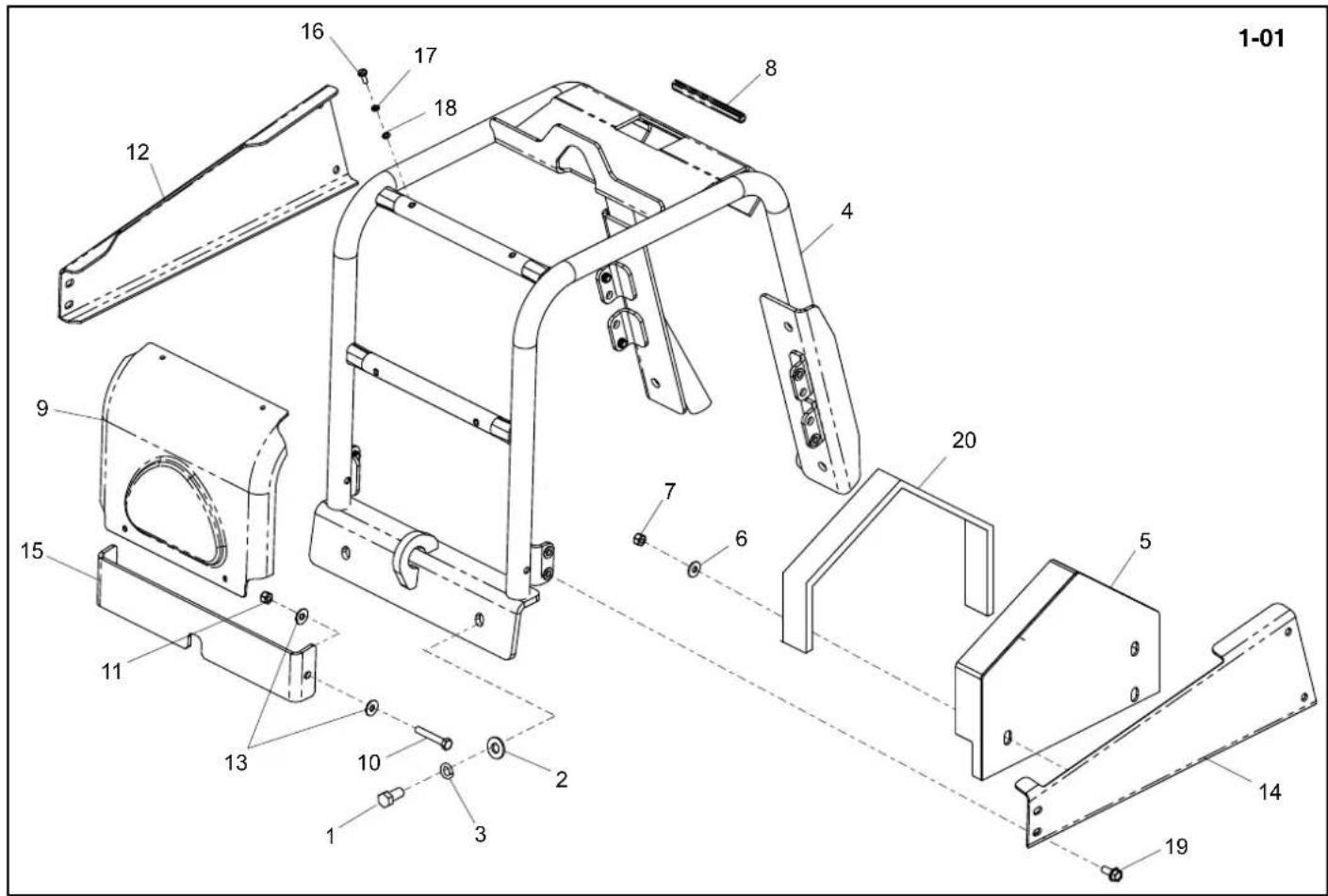
1-01 8 16 17 18 4 20 9 7 6 5 15 11 13 10 2 3 1 14 19Frame Assembly, Ensemble Châssis, Conjunto de Estructura, Conjunto da Estrutura →1030036
1-01
| 1 | 7/12004 | Screw | Vis | Tornillo | Parafuso | M12 X 25 | 4 |
| 2 | 4/1201 | Washer | Rondelle | Arandela | Anilha | M12 | 6 |
| 3 | 4/1202 | Washer | Rondelle | Arandela | Anilha | M12 | 6 |
| 4 | 161.0.213 | Frame | Châssis | Estructura | Estrutura | 1 | |
| 5 | 161.0.191 | Belt Guard | Capot de courroie | Protector de la correa | Guarda da Cinta | 1 | |
| 6 | 4/8007 | Washer | Rondelle | Arandela | Anilha | M8 | 3 |
| 7 | 8/8008 | Nut | Ecrou | Tuerca | Porca | M8 | 3 |
| 8 | 21.0.338 | Edging Strip | Gaine Protection | Banda Protectora | Fita de rebordo | x | |
| 9 | 161.0.216 | Cover - Orange | Couvercle - Orange | Cubierta - Naranja | Tampa - Laranja | 1 | |
| 9 | 161.0.367 | Cover - Green | Couvercle - Grun | Cubierta - Verde | Tampa - Verde | 1 | |
| 9 | 161.0.368 | Cover - Yellow | Couvercle - Jaune | Cubierta - Amarillo | Tampa - Amarelo | 1 | |
| 9 | 161.0.369 | Cover - Blue | Couvercle - Bleu | Cubierta - Azúl | Tampa - Azul | 1 | |
| 10 | 9/8014 | Bolt | Boulon | Perno | Perno | M8 x 50 | 2 |
| 11 | 8/8008 | Nut | Ecrou | Tuerca | Porca | M8 | 2 |
| 12 | 161.0.347 | Cover - Orange | Couvercle - Orange | Cubierta - Naranja | Tampa - Laranja | 1 | |
| 12 | 161.0.361 | Cover - Green | Couvercle - Grun | Cubierta - Verde | Tampa - Verde | 1 | |
| 12 | 161.0.362 | Cover - Yellow | Couvercle - Jaune | Cubierta - Amarillo | Tampa - Amarelo | 1 | |
| 12 | 161.0.363 | Cover - Blue | Couvercle - Bleu | Cubierta - Azúl | Tampa - Azul | 1 | |
| 13 | 4/8007 | Washer | Rondelle | Arandela | Anilha | M8 | 4 |
| 14 | 161.0.348 | Cover - Orange | Couvercle - Orange | Cubierta - Naranja | Tampa - Laranja | 1 | |
| 14 | 161.0.364 | Cover - Green | Couvercle - Grun | Cubierta - Verde | Tampa - Verde | 1 | |
| 14 | 161.0.365 | Cover - Yellow | Couvercle - Jaune | Cubierta - Amarillo | Tampa - Amarelo | 1 | |
| 14 | 161.0.366 | Cover - Blue | Couvercle - Bleu | Cubierta - Azúl | Tampa - Azul | 1 | |
| 15 | 161.0.349 | Cover - Orange | Couvercle - Orange | Cubierta - Naranja | Tampa - Laranja | 1 | |
| 15 | 161.0.370 | Cover - Green | Couvercle - Grun | Cubierta - Verde | Tampa - Verde | 1 | |
| 15 | 161.0.371 | Cover - Yellow | Couvercle - Jaune | Cubierta - Amarillo | Tampa - Amarelo | 1 | |
| 15 | 161.0.372 | Cover - Blue | Couvercle - Bleu | Cubierta - Azúl | Tampa - Azul | 1 | |
| 16 | 07.0.403 | Screw | Vis | Tornillo | Parafuso | M5 x 16 | 4 |
| 17 | 4/5002 | Washer | Rondelle | Arandela | Anilha | M5 | 4 |
| 18 | 05.3.017 | Washer | Rondelle | Arandela | Anilha | M5 | 4 |
| 19 | 7/8037 | Screw | Vis | Tornillo | Parafuso | M8 X 20 | 8 |
| 20 | 21.0.337 | Edging Strip | Gaine Protection | Banda Protectora | Fita de rebordo | x |

text_image
1-01 8 16 17 18 4 20 9 7 6 5 15 11 13 10 2 3 1 14 19| Frame, Rahmen kpl., Hovedstel Og Dæksel, Gruppo Telaio→1030036 | 1-01 |
| 1 | 7/12004 | Schroef | Schraube | Skrue | Vite | M12 X 25 | 4 |
| 2 | 4/1201 | Afdichtring | Scheibe | Spændeskive | Rondella | M12 | 6 |
| 3 | 4/1202 | Afdichtring | Scheibe | Spændeskive | Rondella | M12 | 6 |
| 4 | 161.0.213 | Frame | Rahmen | Hovedstel | Telaio | 1 | |
| 5 | 161.0.191 | Riembeschermkap | Treibriemen-Schutzabdeckung | Rembeskyttelse | Protezione della cinghia | 1 | |
| 6 | 4/8007 | Afdichtring | Scheibe | Spændeskive | Rondella | M8 | 3 |
| 7 | 8/8008 | Moer | Mutter | Motrik | Dado | M8 | 3 |
| 8 | 21.0.338 | Kantstrip | Kantenschutz | Käntband | Guaina Protettiv | x | |
| 9 | 161.0.216 | Deksel - Oranje | Abdeckung - Orange | Dæk - Orange | Coperchio - Arancione | 1 | |
| 9 | 161.0.367 | Deksel - Groen | Abdeckung - Grün | Dæk - Gron | Coperchio - Verde | 1 | |
| 9 | 161.0.368 | Deksel - Geel | Abdeckung - Blau | Dæk - Gul | Coperchio - Giallo | 1 | |
| 9 | 161.0.369 | Deksel - Blauw | Abdeckung - Gelb | Dæk - Blå | Coperchio - Blu | 1 | |
| 10 | 9/8014 | Schroef | Schraube | Skrue | Vite | M8 x 50 | 2 |
| 11 | 8/8008 | Moer | Mutter | Motrik | Dado | M8 | 2 |
| 12 | 161.0.347 | Deksel - Oranje | Abdeckung - Orange | Dæk - Orange | Coperchio - Arancione | 1 | |
| 12 | 161.0.361 | Deksel - Groen | Abdeckung - Grün | Dæk - Gron | Coperchio - Verde | 1 | |
| 12 | 161.0.362 | Deksel - Geel | Abdeckung - Blau | Dæk - Gul | Coperchio - Giallo | 1 | |
| 12 | 161.0.363 | Deksel - Blauw | Abdeckung - Gelb | Dæk - Blå | Coperchio - Blu | 1 | |
| 13 | 4/8007 | Afdichtring | Scheibe | Spændeskive | Rondella | M8 | 4 |
| 14 | 161.0.348 | Deksel - Oranje | Abdeckung - Orange | Dæk - Orange | Coperchio - Arancione | 1 | |
| 14 | 161.0.364 | Deksel - Groen | Abdeckung - Grün | Dæk - Gron | Coperchio - Verde | 1 | |
| 14 | 161.0.365 | Deksel - Geel | Abdeckung - Blau | Dæk - Gul | Coperchio - Giallo | 1 | |
| 14 | 161.0.366 | Deksel - Blauw | Abdeckung - Gelb | Dæk - Blå | Coperchio - Blu | 1 | |
| 15 | 161.0.349 | Deksel - Oranje | Abdeckung - Orange | Dæk - Orange | Coperchio - Arancione | 1 | |
| 15 | 161.0.370 | Deksel - Groen | Abdeckung - Grün | Dæk - Gron | Coperchio - Verde | 1 | |
| 15 | 161.0.371 | Deksel - Geel | Abdeckung - Blau | Dæk - Gul | Coperchio - Giallo | 1 | |
| 15 | 161.0.372 | Deksel - Blauw | Abdeckung - Gelb | Dæk - Blå | Coperchio - Blu | 1 | |
| 16 | 07.0.403 | Schroef | Schraube | Skrue | Vite | M5 x 16 | 4 |
| 17 | 4/5002 | Afdichtring | Scheibe | Spændeskive | Rondella | M5 | 4 |
| 18 | 05.3.017 | Afdichtring | Scheibe | Spændeskive | Rondella | M5 | 4 |
| 19 | 7/8037 | Schroef | Schraube | Skrue | Vite | M8 X 20 | 8 |
| 20 | 21.0.337 | Kantstrip | Kantenschutz | Käntband | Gaina Protettiv | x |
text_image
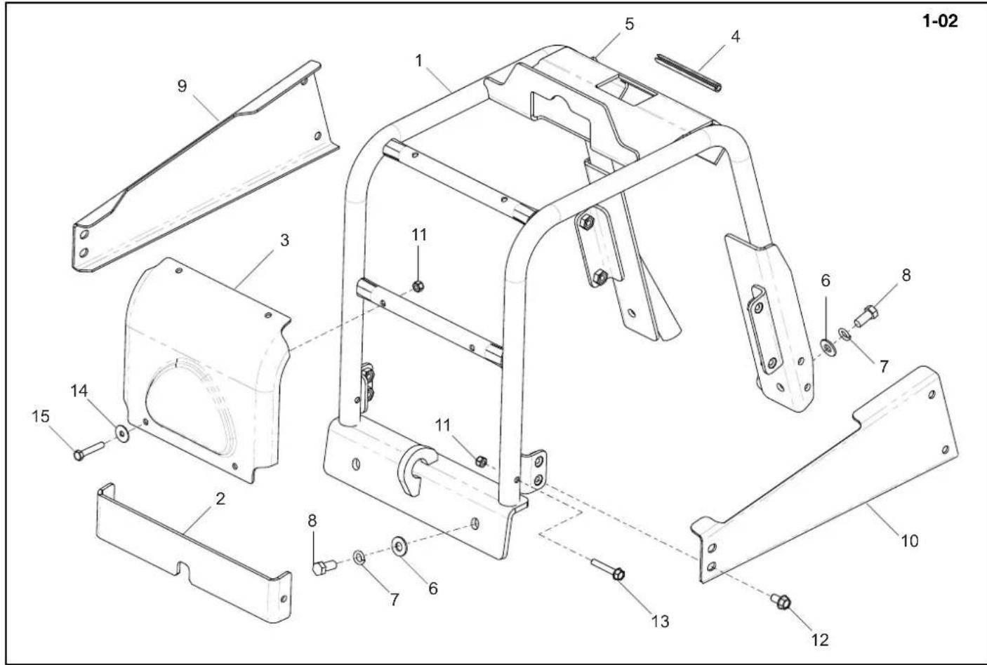
1-02 5 4 1 9 3 11 6 8 7 11 10 2 8 7 6 13 12 15 14Frame Assembly, Ensemble Châssis, Conjunto de Estructura, Conjunto da Estrutura
1-02
030037
| 1 | 161/08700....Frame....Chássis....Estructura....Estrutura....M12 X 25....1 |
| 2 | 161/99682S....Cover - Orange....Couvercle - Orange....Cubierta - Naranja....Tampa - Laranja....1 |
| 2 | 161/99682G....Cover - Green....Couvercle - Grun....Cubierta - Verde....Tampa - Verde....1 |
| 2 | 161/99682Y....Cover - Yellow....Couvercle - Jaune....Cubierta - Amarillo....Tampa - Amarelo....1 |
| 2 | 161/99682B....Cover - Blue....Couvercle - Bleu....Cubierta - Azúl....Tampa - Azul....1 |
| 2 | 161/99682R....Cover - Red....Couvercle - Rouge....Cubierta - Roja....Tampa - Vermelho....1 |
| 2 | 161/99682W....Cover - White....Couvercle - Blanc....Cubierta - Blanco....Tampa - Branco....1 |
| 3 | 161/99683S....Front Cover - Orange....Couvercle Avant - Orange....Cubierta Delantera - Naranja....Tampa Frontal - Laranja....1 |
| 3 | 161/99683G....Front Cover - Green....Couvercle Avant - Grun....Cubierta Delantera - Verde....Tampa Frontal - Verde....1 |
| 3 | 161/99683Y....Front Cover - Yellow....Couvercle Avant - Jaune....Cubierta Delantera - Amarillo....Tampa Frontal - Amarelo....1 |
| 3 | 161/99683B....Front Cover - Blue....Couvercle Avant - Bleu....Cubierta Delantera - Azúl....Tampa Frontal - Azul....1 |
| 3 | 161/99683R....Front Cover - Red....Couvercle Avant - Rouge....Cubierta Delantera - Roja....Tampa Frontal - Vermelho....1 |
| 3 | 161/99683W....Front Cover - White....Couvercle Avant - Blanc....Cubierta Delantera - Blanco....Tampa Frontal - Branco....1 |
| 4 | 161.0.332....Edging Strip....Gaine Protection....Banda Protectora....Fita de rebordo....1 |
| 6 | 4/1201....Washer....Rondelle....Arandela....Anilha....M12....2 |
| 7 | 4/1202....Washer....Rondelle....Arandela....Anilha....M12....2 |
| 8 | 7/12004....Screw....Vis....Tornillo....Parafuso....M12 x 25....2 |
| 9 | 161/99674S....Right Cover - Orange....Couvercle Droite - Orange....Cubierta Derecha - Naranja....Tampa Lado Direito - Laranja....1 |
| 9 | 161/99674G....Right Cover - Green....Couvercle Droite - Grun....Cubierta Derecha - Verde....Tampa Lado Direito - Verde....1 |
| 9 | 161/99674Y....Right Cover - Yellow....Couvercle Droite - Jaune....Cubierta Derecha - Amarillo....Tampa Lado Direito - Amarelo....1 |
| 9 | 161/99674B....Right Cover - Blue....Couvercle Droite - Bleu....Cubierta Derecha - Azúl....Tampa Lado Direito - Azul....1 |
| 9 | 161/99674R....Right Cover - Red....Couvercle Droite - Rouge....Cubierta Derecha - Roja....Tampa Lado Direito - Vermelho....1 |
| 9 | 161/99674W....Right Cover - White....Couvercle Droite - Blanc....Cubierta Derecha - Blanco....Tampa Lado Direito - Branco....1 |
| 10 | 161/99673S....Left Cover - Orange....Couvercle Gauche - Orange....Cubierta Iqzuierda - Naranja....Tampa Lado Esquerdo - Laranja....1 |
| 10 | 161/99673G....Left Cover - Green....Couvercle Gauche - Grun....Cubierta Iqzuierda - Verde....Tampa Lado Esquerdo - Verde....1 |
| 10 | 161/99673Y....Left Cover - Yellow....Couvercle Gauche - Jaune....Cubierta Iqzuierda - Amarillo....Tampa Lado Esquerdo - Amarelo....1 |
| 10 | 161/99673B....Left Cover - Blue....Couvercle Gauche - Bleu....Cubierta Iqzuierda - Azúl....Tampa Lado Esquerdo - Azul....1 |
| 10 | 161/99673R....Left Cover - Red....Couvercle Gauche - Rouge....Cubierta Iqzuierda - Roja....Tampa Lado Esquerdo - Vermelho....1 |
| 10 | 161/99673W....Left Cover - White....Couvercle Gauche - Blanc....Cubierta Iqzuierda - Blanco....Tampa Lado Esquerdo - Branco....1 |
| 11 | 8/8008....Nut....Ecrou....Tuerca....Porca....M8....6 |
| 12 | 7/10039....Screw....Vis....Tornillo....Parafuso....M10 x 30....8 |
| 13 | 7/8037....Screw....Vis....Tornillo....Parafuso....M8 X 20....2 |
| 14 | 4/8008....Washer....Rondelle....Arandela....Anilha....5/16" x 1".4 |
| 15 | 9/8017....Bolt....Boulon....Perno....Perno....M8 x 45....4 |

text_image
1-02 5 4 1 9 3 11 6 8 7 14 15 2 8 7 6 13 10 12| Frame, Rahmen kpl., Hovedstel Og Dæksel, Gruppo Telaio | 1-02 |
| I→ 030037 |
| 1 | 161/08700......Frame......Rahmen......Hovedstel......Telaio......M12 X 25......1 |
| 2 | 161/99682S......Deksel - Oranje......Abdeckung - Orange......Dæk - Orange......Coperchio - Arancione......1 |
| 2 | 161/99682G......Deksel - Groen......Abdeckung - Grün......Dæk - Gron......Coperchio - Verde......1 |
| 2 | 161/99682Y......Deksel - Geel......Abdeckung - Blau......Dæk - Gul......Coperchio - Giallo......1 |
| 2 | 161/99682B......Deksel - Blauw......Abdeckung - Gelb......Dæk - Blå......Coperchio - Blu......1 |
| 2 | 161/99682R......Deksel - Rood......Abdeckung - Rot......Dæk - Rod......Coperchio - Rosso......1 |
| 2 | 161/99682W......Deksel - Wit......Abdeckung - Weiß......Dæk - Hvid......Coperchio - Bianco......1 |
| 3 | 161/99683S......Voordeksel - Oranje......Frontabdeckung - Orange......Forreste kappe - Orange......Copertura anteriore - Arancione......1 |
| 3 | 161/99683G......Voordeksel - Groen......Frontabdeckung - Grün......Forreste kappe - Gron......Copertura anteriore - Verde......1 |
| 3 | 161/99683Y......Voordeksel - Geel......Frontabdeckung - Gelb......Forreste kappe - Gul......Copertura anteriore - Giallo......1 |
| 3 | 161/99683B......Voordeksel - Blauw......Frontabdeckung - Blau......Forreste kappe - Blå......Copertura anteriore - Blu......1 |
| 3 | 161/99683R......Voordeksel - Rood......Frontabdeckung - Rot......Forreste kappe - Rod......Copertura anteriore - Rosso......1 |
| 3 | 161/99683W......Voordeksel - Wit......Frontabdeckung - Weiß......Forreste kappe - Hvid......Copertura anteriore - Bianco......1 |
| 4 | 161.0.332......Kantstrip......Kantenschutz......Käntband......Guaina Protettiv......1 |
| 6 | 4/1201......Afdichtring......Scheibe......Spændeskive......Rondella......M12......2 |
| 7 | 4/1202......Afdichtring......Scheibe......Spændeskive......Rondella......M12......2 |
| 8 | 7/12004......Schroef......Schraube......Skrue......Vite......M12 x 25......2 |
| 9 | 161/99674S......Rechts Deksel - Oranje......Rechts Abdecken - Orange......Højre Dæk - Orange......Coperchio Lato Destro - Arancione......1 |
| 9 | 161/99674G......Rechts Deksel - Groen......Rechts Abdecken - Grün......Højre Dæk - Gron......Coperchio Lato Destro - Verde......1 |
| 9 | 161/99674Y......Rechts Deksel - Geel......Rechts Abdecken - Gelb......Højre Dæk - Gul......Coperchio Lato Destro - Giallo......1 |
| 9 | 161/99674B......Rechts Deksel - Blauw......Rechts Abdecken - Blau......Højre Dæk - Blå......Coperchio Lato Destro - Blu......1 |
| 9 | 161/99674R......Rechts Deksel - Rood......Rechts Abdecken - Rot......Højre Dæk - Rod......Coperchio Lato Destro - Rosso......1 |
| 9 | 161/99674W......Rechts Deksel - Wit......Rechts Abdecken - Weiß......Højre Dæk - Hvid......Coperchio Lato Destro - Bianco......1 |
| 10 | 161/99673S......Linker Deksel - Oranje......Links Abdecken - Orange......Venstre Dæk - Orange......Coperchio Lato sinistro - Arancione......1 |
| 10 | 161/99673G......Linker Deksel - Groen......Links Abdecken - Grün......Venstre Dæk - Gron......Coperchio Lato sinistro - Verde......1 |
| 10 | 161/99673Y......Linker Deksel - Geel......Links Abdecken - Gelb......Venstre Dæk - Gul......Coperchio Lato sinistro - Giallo......1 |
| 10 | 161/99673B......Linker Deksel - Blauw......Links Abdecken - Blau......Venstre Dæk - Blå......Coperchio Lato sinistro - Blu......1 |
| 10 | 161/99673R......Linker Deksel - Rood......Links Abdecken - Rot......Venstre Dæk - Rod......Coperchio Lato sinistro - Rosso......1 |
| 10 | 161/99673W......Linker Deksel -Wit......Links Abdecken - Weiß......Venstre Dæk - Hvid......Coperchio Lato sinistro - Bianco......1 |
| 11 | 8/8008......Moer......Mutter......Møtrik......Dado......M8......6 |
| 12 | 7/10039......Schroef......Schraube......Skrue......Vite......M10 x 30......8 |
| 13 | 7/8037......Schroef......Schraube......Skrue......Vite......M8 X 20......2 |
| 14 | 4/8008......Afdichtring......Scheibe......Spændeskive......Rondella......5/16" x 1"......4 |
| 15 | 9/8017......Bouten......Bolzen......Skruebolte......Bullone......M8 x 45......4 |
2-01
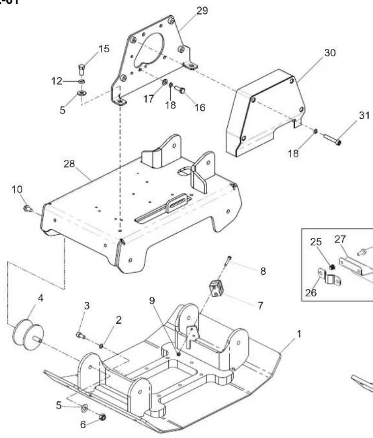
text_image
Technical diagram of a mechanical assembly with numbered components and exploded views
text_image
17A 12 15 11 14 17 18 16 13 161001030036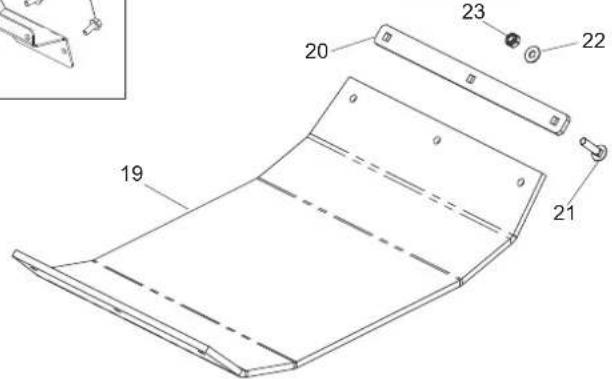
text_image
Technical diagram of a flexible electronic device with labeled parts and an inset view showing a component detail.Baseplate Assembly, Plaque d'embase, Cto. Placa base, Conj. da Placa de Base
2-01
| 1 | 161/00100 | Baseplate | Plaque d'embase | Placa de base | Placa de Base | 400mm | 1 |
| 2 | 161/00200 | Baseplate | Plaque d'embase | Placa de base | Placa de Base | 500mm | 1 |
| 2 | 4/1008 | Washer | Rondelle | Arandela | Anilha | M10 | 1 |
| 3 | 7/10022 | Screw | Vis | Tornillo | Parafuso | M10 X 20 | 1 |
| 4 | 21/0138 | Anti-Vibration Mount | Tampon antivibratoire | Montura antivibratoria | Bloco Anti-vibração | 4 | |
| 5 | 4/1201 | Washer | Rondelle | Arandela | Anilha | M12 | 6 |
| 6 | 8/12006 | Nut | Ecrou | Tuerca | Porca | M12 | 4 |
| 7 | 3/7039 | Clamp Bracket | Équerre de blocage | Escuadra de amarre | Grampo de Fixação. | 1/4" | 1 |
| 8 | 02.0.020 | Screw | Vis | Tornillo | Parafuso | M6 X 50 | 2 |
| 9 | 8/6007 | Nut | Ecrou | Tuerca | Porca | M6 | 2 |
| 10 | 02.5.019 | Screw | Vis | Tornillo | Parafuso | M12 x 20 | 4 |
| 11 | 4/1201 | Washer | Rondelle | Arandela | Anilha | M12 | 6 |
| 12 | 4/1202 | Washer | Rondelle | Arandela | Anilha | M12 | 8 |
| 13 | 161.0.181 | Bedplate | Plaque d'assise | Placa de base | Placa de Apoio | 1 | |
| 14 | 161.0.187 | Belt Guard | Capot de courroie | Protector de la correa | Guarda da Cinta | 1 | |
| 15 | 7/12004 | Screw | Vis | Tornillo | Parafuso | M12 X 20 | 4 |
| 16 | 7/10010 | Screw | Vis | Tornillo | Parafuso | Hatz | 7 |
| 16 | 02.3.020 | Screw | Vis | Tornillo | Parafuso | Honda | 6 |
| 16 | 7/10040 | Screw | Vis | Tornillo | Parafuso | Lombardini | 4 |
| 17 | 4/1005 | Washer | Rondelle | Arandela | Anilha | Hatz | 7 |
| 17 | 4/8006 | Washer | Rondelle | Arandela | Anilha | Honda | 6 |
| 17A | 4/8006 | Washer | Rondelle | Arandela | Anilha | Honda | 3 |
| 18 | 4/1003 | Washer | Rondelle | Arandela | Anilha | Hatz & Lombardini | 11 |
| 18 | 4/8003 | Washer | Rondelle | Arandela | Anilha | Honda | 6 |
| 19A | 161/99601 | Paving Pad | Tampon de Pavage | Tampón de Pavimentación | Bloco de Pavimentação | 400 | 1 |
| 19B | 161/99602 | Paving Pad | Tampon de Pavage | Tampón de Pavimentación | Bloco de Pavimentação | 500 | 1 |
| 20A | 161/99605 | Clamp | Serrage | Mordaza | Grampo | 400 | 2 |
| 20B | 161/99606 | Clamp | Serrage | Mordaza | Grampo | 500 | 2 |
| 21 | 9/10020 | Bolt | Boulon | Perno | Perno | M10 x 45 | 6 |
| 22 | 4/1004 | Washer | Rondelle | Arandela | Anilha | M10 | 6 |
| 23 | 8/10006 | Nut | Ecrou | Tuerca | Porca | M10 | 6 |
| 24 | 7/8037 | Screw | Vis | Tornillo | Parafuso | M8 X 20 | 4 |
| 25 | 01.5.036 | Nut | Ecrou | Tuerca | Porca | M8 | 2 |
| 26 | 161/99575 | Clip | Collier | Presilla | Grampo | 1 | |
| 27 | 161/99576 | Clamp Bracket | Équerre de blocage | Escuadra de amarre | Grampo de Fixação | 1 | |
| 28 | 161/10300 | Bedplate | Plaque d'assise | Placa de base | Placa de Apoio | 1 | |
| 29 | 161/09600 | Backplate | Plaque arrière | Placa trasera | Placa de Apoio | 1 | |
| 30 | 161/09700 | Belt Guard | Capot de courroie | Protector de la correa | Guarda da Cinta | 1 | |
| 31 | 7/10040 | Screw | Vis | Tornillo | Parafuso | M10 X 55 | 4 |
2-01

text_image
Technical diagram of a mechanical assembly with numbered components and exploded views
text_image
17A 12 11 15 14 17 18 16 13 161001030036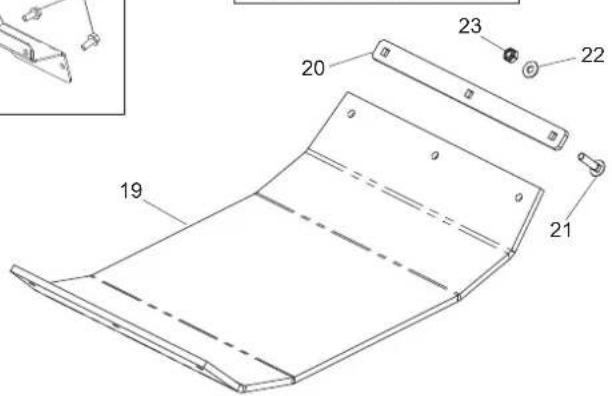
text_image
Technical diagram of a flexible electronic device with labeled components and partsVloerplaat, Rüttelplatten-Zsb., Bundplade, Gruppo piastra di base
2-01
| 1 | 161/00100 | Vloerplaat | Rüttelplatten | Bundplade | Piastra di base | 400mm | 1 |
| 1 | 161/00200 | Vloerplaat | Rüttelplatten | Bundplade | Piastra di base | 500mm | 1 |
| 2 | 4/1008 | Afdichtring | Scheibe | Spændeskive | Rondella | M10 | 1 |
| 3 | 7/10022 | Schroef | Schraube | Skrue | Vite | M10 X 20 | 1 |
| 4 | 21/0138 | Anti-trilbevestiging | Schwingungsdämpfer | Antivibrationsophæng | Supporto antivibrazioni | 4 | |
| 5 | 4/1201 | Afdichtring | Scheibe | Spændeskive | Rondella | M12 | 6 |
| 6 | 8/12006 | Moer | Mutter | Motrik | Dado | M12 | 4 |
| 7 | 3/7039 | Klembeugel | Halteklemme | Fikseringsbeslag | Staffa di serraggio | 1/4" | 1 |
| 8 | 02.0.020 | Schroef | Schraube | Skrue | Vite | M6 X 50 | 2 |
| 9 | 8/6007 | Moer | Mutter | Motrik | Dado | M6 | 2 |
| 10 | 02.5.019 | Schroef | Schraube | Skrue | Vite | M12 x 20 | 4 |
| 11 | 4/1201 | Afdichtring | Scheibe | Spændeskive | Rondella | M12 | 6 |
| 12 | 4/1202 | Afdichtring | Scheibe | Spændeskive | Rondella | M12 | 8 |
| 13 | 161.0.181 | Grondplaat | Sohlplatte | Fundamentplade | Piastra di base | 1 | |
| 14 | 161.0.187 | Riembeschermkap | Treibriemen-Schutzabdeckung | Rembeskyttelse | Protezione della cinghia | 1 | |
| 15 | 7/12004 | Schroef | Schraube | Skrue | Vite | M12 X 20 | 4 |
| 16 | 7/10010 | Schroef | Schraube | Skrue | Vite | Hatz | 7 |
| 16 | 02.3.020 | Schroef | Schraube | Skrue | Vite | Honda | 6 |
| 16 | 7/10040 | Schroef | Schraube | Skrue | Vite | Lombardini | 4 |
| 17 | 4/1005 | Afdichtring | Scheibe | Spændeskive | Rondella | Hatz | 7 |
| 17 | 4/8006 | Afdichtring | Scheibe | Spændeskive | Rondella | Honda | 6 |
| 17A | 4/8006 | Afdichtring | Scheibe | Spændeskive | Rondella | Honda | 3 |
| 18 | 4/1003 | Afdichtring | Scheibe | Spændeskive | Rondella | Hatz & Lombardini | 11 |
| 18 | 4/8003 | Afdichtring | Scheibe | Spændeskive | Rondella | Honda | 6 |
| 19A | 161/99601 | Kunststof onderplaat | Blockpflaster | Belægningsklods | Pavimentazione a Blocchi | 400 | 1 |
| 19B | 161/99602 | Kunststof onderplaat | Blockpflaster | Belægningsklods | Pavimentazione a Blocchi | 500 | 1 |
| 20A | 161/99605 | Klem | Schelle | Klemme | Morsetto | 400 | 2 |
| 20B | 161/99606 | Klem | Schelle | Klemme | Morsetto | 500 | 2 |
| 21 | 9/10020 | Bout | Bolzen | Skruebolt | Bullone | M10 x 45 | 6 |
| 22 | 4/1004 | Afdichtring | Scheibe | Spændeskive | Rondella | M10 | 6 |
| 23 | 8/10006 | Moer | Mutter | Motrik | Dado | M10 | 6 |
| 24 | 7/8037 | Schroef | Schraube | Skrue | Vite | M8 X 20 | 4 |
| 25 | 01.5.036 | Moer | Mutter | Motrik | Dado | M8 | 2 |
| 26 | 161/99575 | Klem | Clip | Klemme | Fermaglio | 1 | |
| 27 | 161/99576 | Klembeugel | Halteklemme | Fikseringsbeslag | Staffa di serraggio | 1 | |
| 28 | 161/10300 | Grondplaat | Sohlplatte | Fundamentplade | Piastra di base | 1 | |
| 29 | 161/09600 | Achterplaat | Rückwand | Bagplade | Piastra di rinforzo | 1 | |
| 30 | 161/09700 | Riembeschermkap | Treibriemen-Schutzabdeckung | Rembeskyttelse | Protezione della cinghia | 1 | |
| 31 | 7/10040 | Schroef | Schraube | Skrue | Vite | M10 X 55 | 4 |

text_image
3-01 1 25 26 27 35 3 29 32 x 2 7 15 16 17 18 35 34 19 4 5 33 35 3 31 20/30 21 24 2 12 13 14 11 23 6 22Handle Assembly, Ensemble poignée, Conjunto de manillar, Conjunto do Punho
3-01
| 1 | 4-01 | Pump | Ressort | Muelle | Mola | 1 |
| 2 | 161.0.248 | Handle | Guidon | Manillar | Punho | 1 |
| 3 | 7/8012 | Screw | Vis | Tornillo | Parafuso | M8 x 25 |
| 4 | 161/27300 | Washer | Rondelle | Arandela | Anilha | →093553 |
| 4 | 4/8006 | Washer | Rondelle | Arandela | Anilha | →093554 |
| 5 | Item 33 | Nut | Ecrou | Tuerca | Porca | M8 |
| 6 | 21.0.187 | Anti-Vibration Mount | Tampon antivibratoire | Montura antivibratoria | Bloco Anti-vibração | 2 |
| 7 | 161.0.247 | Cover | Couvercle | Cubierta | Tampa | 1 |
| 8 | 02.0.014 | Screw | Vis | Tornillo | Parafuso | M6 x 20 |
| 9 | 4/6001 | Washer | Rondelle | Arandela | Anilha | M6 |
| 10 | 4/6005 | Washer | Rondelle | Arandela | Anilha | M6 |
| 11 | 21.0.333 | Rubber Stop | Butée en caoutchouc | Tope de caucho | Batente de Borracha | 1 |
| 12 | 02.0.089 | Screw | Vis | Tornillo | Parafuso | M10 x 100 |
| 13 | 4/1005 | Washer | Rondelle | Arandela | Anilha | M10 |
| 14 | 8/10003 | Nut | Ecrou | Tuerca | Porca | M10 |
| 15 | 19.0.843 | Handle | Guidon | Manillar | Punho | 1 |
| 16 | 161/27300 | Threaded Rod | Tube fileté | Tubo roscado | Tubo roscado | →093553 |
| 16 | 161/99806 | Threaded Rod | Tube fileté | Tubo roscado | Tubo roscado | →093554 |
| 17 | 161.0.240 | Latch | Verrou | Cerrojo | Trinco | 1 |
| 18 | 19.0.095 | Spring | Ressort | Resorte | Mola | 1 |
| 19 | 161/27300 | Latch | Verrou | Cerrojo | Trinco | →093553 |
| 19 | 161.0.238 | Latch | Verrou | Cerrojo | Trinco | →093554 |
| 20 | 7/8008 | Screw | Vis | Tornillo | Parafuso | M8 x 16 |
| 21 | 4/8003 | Washer | Rondelle | Arandela | Anilha | M8 |
| 22 | 8/16005 | Nut | Ecrou | Tuerca | Porca | M16 |
| 23 | 161/99534 | Bolt | Boulon | Perno | Perno | M16 |
| 24 | 4/8004 | Washer | Rondelle | Arandela | Anilha | M8 x 25 x 2 |
| 25 | 161/99658 | Handle - Grey | Guidon - Gris | Manillar - Gris | Punho - Cinzento | 2 |
| 25A | Item 32 | Handle - Orange | Guidon - Orange | Manillar - Naraja | Punho - Laranja | 2 |
| 25B | Item 32 | Handle - AP Green | Guidon - Grun | Manillar - Verde | Punho - Verde | 2 |
| 25C | Item 32 | Handle - Yellow | Guidon - Jaune | Manillar - Azul | Punho - Azul | 2 |
| 25D | Item 32 | Handle - Blue | Guidon - Bleu | Manillar - Amarillo | Punho - Amarelo | 2 |
| 26 | 9/10007 | Bolt | Boulon | Perno | Perno | M10 x 50 |
| 27 | 4/1005 | Washer | Rondelle | Arandela | Anilha | M10 |
| 28 | 4/1003 | Washer | Rondelle | Arandela | Anilha | M10 |
| 29 | 30/0079 | Hose | Durit | Flexible | Tubagem | 1 |
| 30 | 02.0.086 | Screw | Vis | Tornillo | Parafuso | M8 x 12 |
| 31 | 3/7012 | Clip | Collier | Presilla | Grampo | 1 |
| 32 | 161/07700 | Handle Kit | Kit de Guidon | Kit Manillar | Kit do Punho | 1 |
| 33 | 161/27300 | Screw | Vis | Tornillo | Parafuso | →093553 |
| 33 | 7/8032 | Screw | Vis | Tornillo | Parafuso | →093554 |
| 34 | 161/99805 | Spacer | Entretoise | Espaciador | Espaçador | 2 |
| 35 | 4/8006 | Washer | Rondelle | Arandela | Anilha | M8 |

text_image
3-01 1 25 26 27 35 3 29 32 x 2 7 15 16 17 18 35 34 19 4 5 33 35 3 31 20/30 21 24 2 12 13 14 11 23 6 22Hendel, Griff-Zsb., Hovedstel Og Dæksel, Gruppo impugnatura
3-01
| 1 | 4-01 | Pomp | Pumpe | Kontrolpumpeenhed | Bomba | 1 |
| 2 | 161.0.248 | Hendel | Griff | Händtag | Impugnatura | 1 |
| 3 | 7/8012 | Schroef | Schraube | Skrue | Vite | M8 x 25 |
| 4 | 161/27300 | Afdichtring | Scheibe | Spændeskive | Rondella | →093553 |
| 4 | 4/8006 | Afdichtring | Scheibe | Spændeskive | Rondella | →093554 |
| 5 | Item 33 | Moer | Mutter | Motrik | Dado | M8 |
| 6 | 21.0.187 | Anti-trilbevestiging | Schwingungsdämpfer | Antivibrationsophaeng | Supporto antivibrazioni | 2 |
| 7 | 161.0.247 | Deksel | Abdeckung | Dæk | Coperchio | 1 |
| 8 | 02.0.014 | Schroef | Schraube | Skrue | Vite | M6 x 20 |
| 9 | 4/6001 | Afdichtring | Scheibe | Spændeskive | Rondella | M6 |
| 10 | 4/6005 | Afdichtring | Scheibe | Spændeskive | Rondella | M6 |
| 11 | 21.0.333 | Aanslagrubber | Gummianschlag | Gummistop | Arresto in gomma | 1 |
| 12 | 02.0.089 | Schroef | Schraube | Skrue | Vite | M10 x 100 |
| 13 | 4/1005 | Afdichtring | Scheibe | Spændeskive | Rondella | M10 |
| 14 | 8/10003 | Moer | Mutter | Motrik | Dado | M10 |
| 15 | 19.0.843 | Hendel | Griff | Händtag | Impugnatura | 1 |
| 16 | 161/27300 | Draadbuis | Gewinderohr | Gevindskåret rør | Tubo filettato | →093553 |
| 16 | 161/99806 | Draadbuis | Gewinderohr | Gevindskåret rør | Tubo filettato | →093554 |
| 17 | 161.0.240 | Grendel | Riegel | Sicherheits | Saliscendi | 1 |
| 18 | 19.0.095 | Veer | Feder | Fjeder | Molla | 1 |
| 16 | 161/27300 | Grendel | Riegel | Sicherheits | Saliscendi | →093553 |
| 19 | 161.0.238 | Grendel | Riegel | Sicherheits | Saliscendi | →093554 |
| 20 | 7/8008 | Schroef | Schraube | Skrue | Vite | M8 x 16 |
| 21 | 4/8003 | Afdichtring | Scheibe | Spændeskive | Rondella | M8 |
| 22 | 8/16005 | Moer | Mutter | Motrik | Dado | M16 |
| 23 | 161/99534 | Schroef | Schraube | Skrue | Vite | M16 |
| 24 | 4/8004 | Afdichtring | Scheibe | Spændeskive | Rondella | M8 x 25 x 2 |
| 25 | 161/99658 | Hendel - Grijs | Griff - Grau | Manillar - Grå | Punho - Grigio | 2 |
| 25A | Item 32 | Hendel - Oranje | Griff - Orange | Händtag - Orange | Impugnatura - Arancione | 2 |
| 25B | Item 32 | Hendel - Groen | Griff - Grün | Händtag - Grøn | Impugnatura - Verde | 2 |
| 25C | Item 32 | Hendel - Geel | Griff - Gelb | Händtag - Gul | Impugnatura - Giallo | 2 |
| 25D | Item 32 | Hendel - Blauw | Griff - Blau | Händtag - Blå | Impugnatura - Blu | 2 |
| 26 | 9/10007 | Schroef | Schraube | Skrue | Vite | M10 x 50 |
| 27 | 4/1005 | Afdichtring | Scheibe | Spændeskive | Rondella | M10 |
| 28 | 4/1003 | Afdichtring | Scheibe | Spændeskive | Rondella | M10 |
| 29 | 30/0079 | Slang | Schlauchstück | Slange | Flessibile | 1 |
| 30 | 02.0.086 | Schroef | Schraube | Skrue | Vite | M8 x 12 |
| 31 | 3/7012 | Klem | Clip | Klemme | Fermaglio | 1 |
| 32 | 161/07700 | Hendelset | Griffsatz | Händtagskit | Kit Impugnatura | 1 |
| 33 | 161/27300 | Screw | Vis | Tornillo | Parafuso | →093553 |
| 33 | 7/8032 | Screw | Vis | Tornillo | Parafuso | →093554 |
| 34 | 161/99805 | Spacer | Entretoise | Espaciador | Espaçador | 2 |
| 35 | 4/8006 | Washer | Rondelle | Arandela | Anilha | M8 |

text_image
Exploded view diagram of a mechanical assembly with numbered parts for identification
text_image
5 6 8 3 9 1 2 10 14 12 4 13 14 15 7 16 17 18 22 20 21 19 →16108001297.4-01
Pump Assembly, Pompa, Bomba, Conj. Bomba
4-01
| 1 | 03.0.033 | Screw | Vis | Tornillo | Parafuso | M5 X 8 | 2 |
| 2 | 161.0.149 | Handle Head | Tête de poignée | Cabeza del asa | Punho do Manípulo | 1 | |
| 3 | 161.0.150 | Pinion Rack | Crémaillère de pignon | Barra de piñones | Cremalheira de Pinhão | 1 | |
| 4 | 161.0.151 | Pinion Shaft | Axe de pignon | Eje de piñón | Veio do Pinhão | 1 | |
| 5 | 03.0.031 | Plug | Bougie | Tapón | Bujão | M36 x 1.5 | 1 |
| 6 | 161.0.158 | Gasket | Joint | Junta | Gaxeta | 1 | |
| 7 | 161.0.152 | Plate | Plaque | Plato | Placa | 1 | |
| 8 | 161.0.157 | Bush | Douille | Buje | Bucha | 1 | |
| 9 | 15.0.320 | Seal | Joint d'étanchéité | Obturador | Vedação | M30 x 20 x 9 | 1 |
| 10 | 15.0.321 | O-Ring | Joint torique | Junta tórica | Anel Vedante | M30 x 2 | 1 |
| 11 | 15.0.322 | O-Ring | Joint torique | Junta tórica | Anel Vedante | M4 x 2 | 1 |
| 12 | 15.0.323 | O-Ring | Joint torique | Junta tórica | Anel Vedante | M36.5 x 2.65 | 1 |
| 13 | 15.0.324 | O-Ring | Joint torique | Junta tórica | Anel Vedante | M20 x 2.65 | 2 |
| 14 | 05.3.077 | Washer | Rondelle | Arandela | Anilha | 2 | |
| 15 | 05.3.068 | Circlip | Circlip | Resorte circular | Grampo circular | 1 | |
| 16 | 14.0.107 | Adaptor | Adapteur | Adaptador | Adaptador | 1/4"X1/4" | 1 |
| 17 | 15.0.325 | Bonded Seal | Joint collé | Obturador aglomerado | Vedação Unida | 1/4" | 1 |
| 18 | 161/07000 | Bracket | Patte de montage | Escuadra | Suporte | 1 | |
| 19 | 07.0.028 | Screw | Vis | Tornillo | Parafuso | M8 x 30 | 4 |
| 20 | 4/8006 | Washer | Rondelle | Arandela | Anilha | M8 | 4 |
| 21 | 4/8003 | Washer | Rondelle | Arandela | Anilha | M8 | 4 |
| 22 | 8/6011 | Nut | Ecrou | Tuerca | Porca | M6 | 2 |
| 23 | 50/000066 | Bush | Douille | Buje | Bucha | 1 | |
| 24 | 161/99643 | Pinion Rack | Crémaillère de pignon | Barra de piñones | Cremalheira de Pinhão | 1 | |
| 25 | 161/99637 | Handle Head | Tête de poignée | Cabeza del asa | Punho do Manípulo | 1 | |
| 26 | 5/0065 | O-Ring | Joint torique | Junta tórica | Anel Vedante | 1 | |
| 27 | 161/99641 | Piston Guide | Guide de piston | Guía de pistón | Pino do Pistão | 1 |
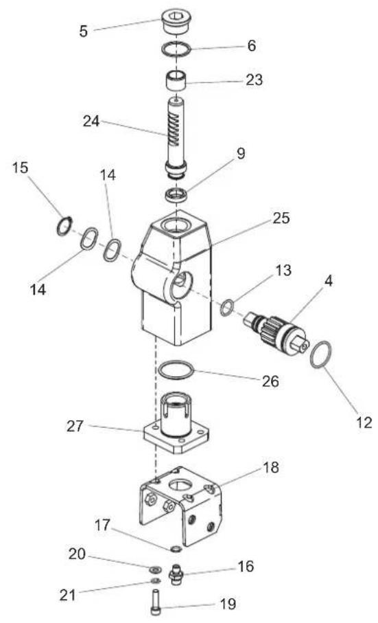
text_image
Exploded view diagram of a mechanical assembly with numbered parts for identification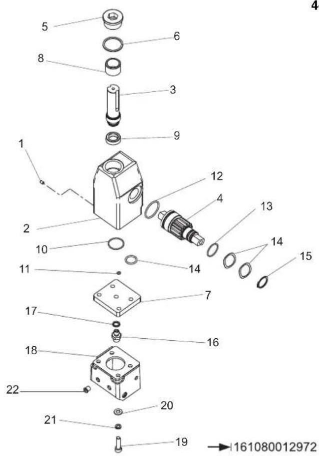
text_image
5 6 8 3 9 1 2 10 11 12 4 13 14 15 7 16 17 18 22 20 21 19 →161080012972Pomp, Compleet, Pumpe, Kontrolpumpeenhed, Pompa
4-01
| 1 | 03.0.033 | Schroef | Schraube | Skrue | Vite | M5 X 8 | 2 |
| 2 | 161.0.149 | Hendelkop | Griffkopf | Håndtagshoved | Impugnatura maniglia | 1 | |
| 3 | 161.0.150 | Rondsel en heugel | Zahnstange | Tandstang | Cremagliera pignone | 1 | |
| 4 | 161.0.151 | Pinion Shaft | Axe de pignon | Eje de piñón | Veio do Pinhão | 1 | |
| 5 | 03.0.031 | Plug | Verschlussschraube | Prop | Candela | M36 x 1.5 | 1 |
| 6 | 161.0.158 | Tætningsring | Flachdichtung | Pakking | Guarnizione | 1 | |
| 7 | 161.0.152 | Plaat | Platte | Plade | Piastra | 1 | |
| 8 | 161.0.157 | Bus | Busche | Bøsning | Boccola | 1 | |
| 9 | 15.0.320 | Afdichtring | Dichtung | Tætning | Tenuta | M30 x 20 x 9 | 1 |
| 10 | 15.0.321 | O-Ring | O-Ring | O-Ring | O-Ring | M30 x 2 | 1 |
| 11 | 15.0.322 | O-Ring | O-Ring | O-Ring | O-Ring | M4 x 2 | 1 |
| 12 | 15.0.323 | O-Ring | O-Ring | O-Ring | O-Ring | M36.5 x 2.65 | 1 |
| 13 | 15.0.324 | O-Ring | O-Ring | O-Ring | O-Ring | M20 x 2.65 | 2 |
| 14 | 05.3.077 | Afdichtring | Scheibe | Spændeskive | Rondella | 2 | |
| 15 | 05.3.068 | Borgveer | Sprengring | Låsering | Anello Elastico | 1 | |
| 16 | 14.0.107 | Adaptor | Adaptor | Adaptor | Adattatore | 1/4"X1/4" | 1 |
| 17 | 15.0.325 | Inlijmafichting | Klebedichtung | Klæbepakning | Tenuta Incollata | 1/4" | 1 |
| 18 | 161/07000 | Steuin | Halterung | Beslag | Staffe | 1 | |
| 19 | 07.0.028 | Schroef | Schraube | Skrue | Vite | M8 x 30 | 4 |
| 20 | 4/8006 | Afdichtring | Scheibe | Spændeskive | Rondella | M8 | 4 |
| 21 | 4/8003 | Afdichtring | Scheibe | Spændeskive | Rondella | M8 | 4 |
| 22 | 8/6011 | Moer | Mutter | Motrik | Dado | M6 | 2 |
| 23 | 50/000066 | Bus | Busche | Bøsning | Boccola | 1 | |
| 24 | 161/99643 | Rondsel en heugel | Zahnstange | Tandstang | Cremagliera pignone | 1 | |
| 25 | 161-99637 | Hendelkop | Griffkopf | Håndtagshoved | Impugnatura maniglia | 1 | |
| 27 | 5/0065 | O-Ring | O-Ring | O-Ring | O-Ring | 1 | |
| 28 | 161/99641 | Zuigergeleider | Kolbenzapfen | Stempelstyr | Guida del pistone | 1 |

text_image
5-01 1026418 13 9 19 12 10 2 11 20 1 10 11 14 15 2 17 16 18 21 22 28 3 8 7 25 23 24 26 27 5 4 6Gearbox Assembly, Ensemble boîte de vitesses, Conjunto de caja de engranajes, Conjunto da Caixa de Engrenagens
5-01
| 1 | 161/99514....Gearbox Casing....Carter de boîte de vitesses....Envoltura de la transmisión...Estojo da caixa de engrenagens....1 |
| 2 | 12.1.160....Bearing....Roulement....Cojinete....Rolamanto....4 |
| 3 | 161/99507....Shaft....Axe....Eje....Veio....1 |
| 4 | 161/99700....Weight 30....Poids 30....Peso 30....Peso 30....1 |
| 4 | 161/99699....Weight 30....Poids 30....Peso 30....Peso 30....1 |
| 5 | 05.3.067....Washer....Rondelle....Arandela....Anilha....M10....4 |
| 6 | 7/1004....Screw....Vis....Tornillo....Parafuso....M10 x 35....2 |
| 7 | 161/99510....Gear....Pignon....Engranaje....Engrenagen....1 |
| 8 | 161/99512....Key....Clavette....Chaveta....Chave....M10 x 8 x 18....1 |
| 9 | 14.0.108....Plug....Bougie....Tapón....Bujão....1/4"....1 |
| 10 | 161/99504....End Cover....Carter d'extrémité....Tapa de fondo....Tampa de extremidade....2 |
| 11 | 4/6005....Washer....Rondelle....Arandela....Anilha....M6....16 |
| 12 | 7/6040....Screw....Vis....Tornillo....Parafuso....M6 x 20....4 |
| 13 | 15.0.102....Washer....Rondelle....Arandela....Anilha....1/4"....2 |
| 14 | 01.5.036....Nut....Ecrou....Tuerca....Porca....M8....4 |
| 15 | ◇Item 29....Belt Guard....Capot de courroie....Protector de la correa....Guarda da Cinta....1 |
| 16 | ◇Item 29....Cover....Couvercle....Cubierta....Tampa....1 |
| 17 | 7/6041....Screw....Vis....Tornillo....Parafuso....M6 x 25....4 |
| 18 | 7/8037....Screw....Vis....Tornillo....Parafuso....M8 x 20....4 |
| 19 | 10-330-12130....Screw....Vis....Tornillo....Parafuso....M12 x 130....6 |
| 20 | 7/12023....Screw....Vis....Tornillo....Parafuso....M12 x 30....2 |
| 21 | 161/99678....End Cover....Carter d'extrémité....Tapa de fondo....Tampa de extremidade....1 |
| 22 | 161/10100....Guard....Capot....Protector....Guarda....1 |
| 23 | 21.0.029....Edging Strip....Gaine Protection....Banda Protectora....Fita de rebordo....x |
| 24 | 161/99676....Belt Guard....Capot de courroie....Protector de la correa....Guarda da Cinta....1 |
| 25 | 4/8004....Washer....Rondelle....Arandela....Anilha....M8....3 |
| 26 | 4/8003....Washer....Rondelle....Arandela....Anilha....M8....3 |
| 27 | 7/8011....Screw....Vis....Tornillo....Parafuso....M8 x 20....3 |
| 28 | 7/6025....Screw....Vis....Tornillo....Parafuso....M6 x 20....4 |
| 29 | 161/10600....Belt Guard Kit....Ensemble Capot de courroie....Cto. Protector de la correa....Conj. Guarda da Cinta....1 |

text_image
5-01 1026418 13 9 19 12 10 2 11 20 1 10 11 14 15 2 17 16 18 21 22 28 23 25 26 24 27 3 8 7 4 5 6text_image
6-01 1 10 9 30 8 11 31 12 13 16 15 14 23 34 21 33 32 25 28 27 26 3rd July 2008 25 24 29 27 17 20 19 18 Engine Hose Assembly 4 7 5 6 2 3text_image
6-01 1 10 9 30 8 11 31 12 13 16 15 14 23 34 21 33 32 25 28 27 26 3rd July 2008 25 24 29 27 17 20 19 18 Engine Hose Assembly 4 7 5 6 2 3Motor en Aandrijfset, Motor und antriebsbausatz, Motor og gearkit, Motore e Kit trasmissione
6-01
(Hatz & Lombardini)
| 1 | 29.0.462 | Motor | Motor | Motor | Motore | Hatz 1B20 | 1 |
| 1 | 20/0090 | Motor | Motor | Motor | Motore | Lombardini 15LD225 | 1 |
| 2 | 14.0.919 | Slang | Schlauchstück | Slange | Flessibile | 1 | |
| 3 | 14.0.628 | Adaptor | Adaptor | Adaptor | Adattatore | M22 X 1/4" | 1 |
| 4 | 14.0.108 | Plug | Verschlussschraube | Prop | Candela | 1/4" | 1 |
| 5 | 21.0.336 | Klem | Clip | Klemme | Fermaglio | 1 | |
| 6 | 05.1.002 | Afdichtring | Scheibe | Spændeskive | Rondella | M4 | 1 |
| 7 | 7/4002 | Schroef | Schraube | Skrue | Vite | M4 x 12 | 1 |
| 8 | 7/5010 | Schroef | Schraube | Skrue | Vite | M5 x 20 | 2 |
| 9 | 4/5002 | Afdichtring | Scheibe | Spændeskive | Rondella | M5 | 2 |
| 10 | 8/5003 | Moer | Mutter | Motrik | Dado | M5 | 2 |
| 11 | 161/09200 | Gashendel | Drosselklappenhebel | Gashåndtag | Cavo dell'acceleratore | 1 | |
| 12 | 7/8037 | Schroef | Schraube | Skrue | Vite | Hatz | 4 |
| 12 | 7/10024 | Schroef | Schraube | Skrue | Vite | Lombardni | 4 |
| 13 | 10.7.186 | Kuppling | Koppeling | Kobling | Frizione | 1 | |
| 14 | 7/8012 | Schroef | Schraube | Skrue | Vite | M8 x 25 | 1 |
| 15 | 4/8003 | Afdichtring | Scheibe | Spændeskive | Rondella | M8 | 1 |
| 16 | 05.3.062 | Afdichtring | Scheibe | Spændeskive | Rondella | 1 | |
| 17 | 161.0.122 | Poelie | Riemenscheibe | Remskive | Puleggia | 1 | |
| 18 | 161/99513 | Schroef | Schraube | Skrue | Vite | M10 X 20 | 1 |
| 19 | 161/99535 | Spie | Keil | Kile | Chiave | M10 X 8 X 22 | 1 |
| 20 | 4/1009 | Afdichtring | Scheibe | Spændeskive | Rondella | M10 X 40 X 3 | 1 |
| 21 | 53/0016 | Lager | Lager | Leje | Cuscinetto | 1 | |
| 22 | 161/26100 | Pen | Zapfen | Stift | Perno | 1 | |
| 23 | 3/9003 | Borgveer | Sprengring | Låsering | Anello Elastico | 1 | |
| 24 | 161/26100 | Lager | Lager | Leje | Cuscinetto | 1 | |
| 25 | MS22 | Borgveer | Sprengring | Låsering | Anello Elastico | 1 | |
| 26 | 21/0281 | Riem | Riemen | Remmen | Cinghia | 1 | |
| 27 | 7/10003 | Schroef | Schraube | Skrue | Vite | M10x30 | 1 |
| 28 | 4/1003 | Afdichtring | Scheibe | Spændeskive | Rondella | M10 | 1 |
| 29 | 4/1005 | Afdichtring | Scheibe | Spændeskive | Rondella | M10 | 1 |
| 30 | 19.0.962 | Gashendel | Drosselklappenhebel | Gashåndtag | Cavo dell'acceleratore | 1 | |
| 31 | 161/09201 | Gaskabel | Drosselklappenkabel | Gashändtagskabel | Leva dell'acceleratore | 1 | |
| 32 | 4/1013 | Afdichtring | Scheibe | Spændeskive | Rondella | M10 | 1 |
| 33 | 161/99750 | Pen | Zapfen | Stift | Perno | 1 | |
| 34 | 161/99747 | Poelie | Riemenscheibe | Remskive | Puleggia | 1 |
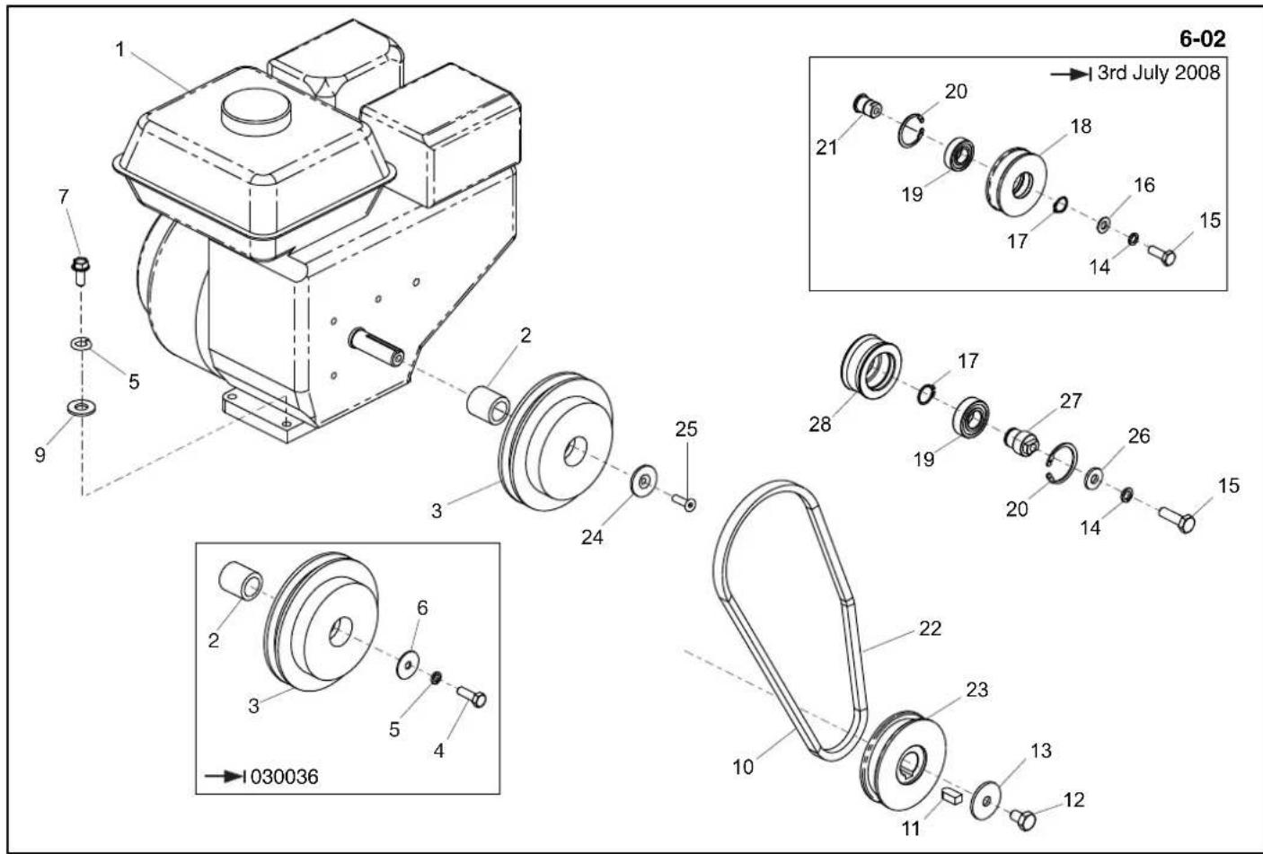
text_image
6-02 →3rd July 2008 1 7 5 9 2 3 24 25 28 17 19 27 26 15 14 14 13 12 11 10 23 22 20 19 21 18 17 16 15 6 3 2 1030036text_image
Technical diagram of a mechanical assembly with numbered components for identificationTransporter Attachments, Fixation de transporteur,
text_image
Technical diagram of a mechanical assembly with numbered components for identificationTransporthulpstuk, Transportvorrichtungs-Halterungen, Transportørudstyr, Trasportatore
7-01
| 1 | 161/99600 | As | Achse | Aksel | Assale | 1 |
| 2 | 161/02800 | Rotoren (Links) | Achse (Links) | Dreje (Venstre) | Perno (Lato Sinistro) | 1 |
| 3 | 161/02900 | Rotoren (Rechts) | Achse (Rechts) | Dreje (Højre) | Perno (Lato Destro) | 1 |
| 4 | 4/1004 | Afdichtring | Scheibe | Spændeskive | Rondella | M10 |
| 5 | 4/1003 | Afdichtring | Scheibe | Spændeskive | Rondella | M10 |
| 6 | 7/10005 | Schroef | Schraube | Skrue | Vite | M10 x 25 |
| 7 | 60/0441 | Wiel | Rad | Hjul | Ruota | 2 |
| 8 | 3/0045 | Pen | Zapfen | Stift | Perno | 6 x 35 |

text_image
1 2 3 2 Belle GROUP RPC 30/50 108 dB RPC 30/50 1 CE I o 8-01Decals, Autocollant, Rótulo, Decalque 8-01
1 161.0.293 ....Decal Warning....Autocollant Avertissement ....Rótulo Aviso....Decalque Aviso....1
2 800/99976 ....Decal 30/40 ....Autocollant 30/40 ....Rótulo 30/40 ....Decalque 30/40 ....1
2 161.0.434 ....Decal 30/50 ....Autocollant 30/50 ....Rótulo 30/50 ....Decalque 30/50 ....1
3 01154.....Decal Noise.....Autocollant Bruits.....Rótulo Ruidos.....Decalque Ruído.....108dBA.....1

text_image
1 2 3 2 LWA 108 dB RPC 30/50 1 2 1 8-01 Belle GROUP RPC 30/50 CE ILabel, Abziehbild, Skilt, Decalcomania
8-01
1 161.0.293 .... Label Waarschuwing .... Abziehbild Warnung .... Skilt Adavarsel .... Decalcomania Avvertenza .... 1
2 800/99976....Label 30/40....Abziehbild 30/40....Skilt 30/40....Decalcomania 30/40....1
2 161.0.434 .... Label 30/50 .... Abziehbild 30/50 .... Skilt 30/50 .... Decalcomania 30/50 .... 1
3 01154 .... Label Guluid .... Geräuschpegelschild .... Skilt Støj .... Decalcomania sulla rumorosità .... 1
No.1 for Light Construction Equipment
Belle Group Head Office
Sheen, Nr. Buxton
Derbyshire.
SK17 OEU
GB.
Tel: +44 (0)1298 84606
Fax: +44 (0)1298 84722
email: sales@belle-group.co.uk
Belle France SARL
1 rue de l'Equerre
ZI de Béthunes
BP 20541
95005 Cergy Pontoise Cedex
FRANCE
Tel: +33 (0) 1 34 21 45 83
Tel: +33 (0) 1 34 21 45 84
Fax: +33 (0) 1 30 37 31 28
Belle Equipos SL
Calle Doctor Calero Cial 19,
Local 22, 28220 Majadahonda
Madrid, Spain
Tel: +34 (0) 91 636 2043
Fax: +34 (0) 91 634 1535
Husumer Straße 45 a,
D-33729,
Bielefield
Deutschland
Tel : +49(0) 5217 707505
Fax: +49 (0) 5217 707506
Sales: 0800 1808069
Spares: 0800 1816673
Belle Poland sp. z.o.o.
96-200 Rawa Mazowiecka
Belle Group Portugal
Belle Group Netherlands
Tel: 0800 249861
Belle Group Belguim
Tel: 0800 80295
Belle Group Austria
Tel: 0800 291544
Belle Group Russia
64 Nevsky pr.
St, Petersburg
Russia
Tel: +7(812)314-81-34
Moscow : +7(495)589-64-32
Belle Group South East Asia
21, Jalan Ara AD 7/3B,
Pandar Sri Damansara
S2200 Kuala Lumpur, Malaysia
Tel: +60 (0) 3 62721678
+60 (0) 3 6272 9308
Fax: +60 (0) 3 6272 9528
Belle Group (GB), Shanghai Office
Room 213, Zhonghuang Building,
1007 Zhongshan Nan Er Road,
Xuhui, Shanghai 200030 China
Tel: 00 - 86 - 21 - 5461 5228
Mobile: 00 - 86 - 133 8172 2653
Fax: 00 - 86 - 21 - 5461 5369
email: morgan.liu@bellegroup.com.cn
Belle Group Inc
3959 Electric Rd
Roanoake
Suite 360
VA 24018. USA.
Tel: +1.540.345.5090
Fax: +1.540.345.5091
Toll free 866 540 5090
e-mail: sales@bellegroup.net

text_image
Belle GROUP Parts CENTREBelle Group World Parts Centre
Sheen, Nr. Buxton
Derbyshire.
SK17 OEU
GB.
Tel: +44 (0)1298 84606
Fax: +44 (0)1298 84722
email: parts@belle-group.co.uk
www.Altrad.com
www.BelleGroup.com

COMPACTING...
MIXING...

CONCRETING...
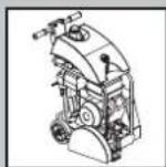
CUTTING...

BREAKING...
MOVING