BELLE PCX 20A - Vibratory plate Lescha - Free user manual and instructions
Find the device manual for free BELLE PCX 20A Lescha in PDF.
| Product type | Vibrating plate |
| Brand | Lescha |
| Model | BELLE PCX 20A |
| Dimensions (L x W x H) in operation | 940 x 500 x 880 mm |
| Dimensions (L x W x H) in storage | 110 x 500 x 625 mm |
| Weight (with watering kit and wheels) | 75 kg |
| Engine | Honda GX120, 4.0 hp / 3.0 kW at 3600 rpm |
| Fuel type | Unleaded gasoline |
| Fuel tank capacity | 2.5 L |
| Engine oil | SAE 30 (0.6 L) |
| Vibrator oil | Turbine oil 32 (0.22 L) |
| Spark plug | BM6ES or BPR6ES (gap 0.7-0.8 mm) |
| Vibration force | 11 kN |
| Frequency | 101 Hz |
| Maximum working speed | 16.3 m/min |
| Compaction force | 420 kg/m² |
| Sound level | 107 dB(A) |
| Maximum daily usage time | 16 min |
| Direction of travel | Unidirectional |
| Transmission | V-belt and centrifugal clutch |
| Base plate | Steel |
| Integrated watering kit | Yes (water tank) |
| Transport wheels | Included |
| Warranty | 12 months |
Frequently Asked Questions - BELLE PCX 20A Lescha
User questions about BELLE PCX 20A Lescha
0 question about this device. Answer the ones you know or ask your own.
Ask a new question about this device
Download the instructions for your Vibratory plate in PDF format for free! Find your manual BELLE PCX 20A - Lescha and take your electronic device back in hand. On this page are published all the documents necessary for the use of your device. BELLE PCX 20A by Lescha.
USER MANUAL BELLE PCX 20A Lescha
natural_image
Abstract white bird-like shape on gradient gray background (no text or symbols)ALTRAD
GB Operators Manual 6
US Operators Manual 14
F Manuel De L'Opérateur 22
E Manual del Operador 30
P Manual de Operação 38
NL Handleiding 46
DK Betjeningsvejledning 54
D Bedienungshandbuch 62
I Manuale Dell'Operatore 70
S Bruksanvisning 78
NO Betjene Håndbok 86
SF Käyttöohje 94
PL Instrukcja Obsługi 102
RUS Руководство для оператора 110
EST Kasutusjuhend 118
LV Lietotāja rokasgrāmata 126
LT Naudojimo Instrukcija 134
BG Оператор Ръчен 142
CZ Na'vod K Obzluze 150
RO Manual de Utilizare 158
HUN Kezelők Kézi 166
HR Uputstvo za rukovatelja 174

text_image
Belle GROUPPCX 20A

natural_image
Technical line drawing of a mechanical pump or motor assembly (no text or symbols)182
- Spare Parts Book
- Pièces détachées
- Libro Despiece
- Lista de Peças
- Onderdelen Boekje
- Reservedele Skrift
- Ersatzteilhandbuch
- Manuale dei ricambi
- Bruksanvisning
- Bruksanvisning
- Varaosaluettelo
- Lista Części Zamiennych
- Запасные части Книга
- Varuosade nimekiri
- Rezerves dalu saraksts
- Atsarginiu daliu sarašas
- Част Списък
- Část Barevný pruh
- Lista Pieselor de Schimb
- Részek Oldalra döl
- Rezervni djelovi Knjiga
EC DECLARATION OF CONFORMITY / DECLARATION CE DE CONFORMITE / DECLARACIÓN DE CONFORMIDAD CE / DECLARAÇÃO CE DE CONFORMIDADE / EG-VERKLARING VAN OVEREENSTEMMING / EF OVERENSSTEMMELSESERKLÆRING

We, Belle Group Sheen UK, Sheen, Nr. Buxton, Derbyshire, SK17 0EU, GB, hereby certify that if the product described within this certificate is bought from an authorised Belle Group dealer within the EEC, it conforms to the following EEC directives: 2006/42/CE (This directive replaces directive 98/37/EC), Electromagnetic Compatibility Directive 2004/108/CE (as amended by 89/336/EEC, 92/31/EEC & 93/68 EEC). The Waste Electrical and Electronic Equipment (WEEE) 2002/96/CE, the low voltage directive 2006/95/CE, BS EN ISO 12100-1:2003 Safety of machinery and associated harmonised standards, where applicable. Noise emissions conform to directive 2000/14/EC Annex VI, for machines under article 12 the notified body is AV Technology Limited, AVTECH house, Birdhall Lane, Cheadle Heath, Stockport, Cheshire, SK3 0XU, GB. Noise Technical Files are held at the Belle Group Head Office address which is stated above.

natural_image
Empty rectangular frame with dashed border (no text or symbols)Signed by:
Signature:
Medido por:
Assinado por:
Getekend door:
Uunderskrevetaf:

text_image
O.NahRay Neilson
Managing Director - On behalf of BELLE GROUP (SHEEN) UK.
Date of Declaration....
SONORA MISURATA / (GARANTITA)
MÄTT / ......(GARANTERAD)
GEWICHT ....
PESO......
VIKT......
PRODUKTTYP......
TUOTETYYPPI......
TYP PRODUKTO......
MODELL
MALLI
MODEL......
SERIE NR.
VALMISTUSNRO......
Nr SERII ....
PRODUKSJONSDATO......
VALMISTUSPÄIVÄ......
DATAPRODUKCJI
ÄLYDKRAFTNIVÅ MÅLT /
ÄNENVOIMAKKUUDEN TASO MITATTU /
POZIOM MOCY DŻWIĘKU ZMIERZONY / ......(GWARANTOWANY)
(GARANTERT)
WAGA......
Unterzeichnet vo:
Firmato da:
Undertecknat:
Signatur:
Allekirjoitus:
Podpisat:

text_image
O.NahRay Neilson
natural_image
Empty white rectangle with dashed border (no text or symbols)Подпись:
Alla kirjutanud:
Paraksts:
Pasiraše:
Подпис:
Υπογραφή:

text_image
O. NathRay Neilson
Director General - in numele BELLE GROUP (SHEEN), UK
This manual has been written to help you operate and service the 'PCX 20A' Plate compactor safely. This manual is intended for dealers and operators of the 'PCX 20A' Plate compactor.
Foreword
The 'Machine Description' section helps you to familiarise yourself with the machine's layout and controls.
The 'Environment' section gives instructions on how to handle the recycling of discarded apparatus in an environmentally friendly way.
The ‘General Safety’ and ‘Health and Safety’ sections explain how to use the machine to ensure your safety and the safety of the general public.
The 'Operating Instructions' section helps you with the setting up and use of the machine.
The 'Trouble Shooting' guide helps you if you have a problem with your machine.
The 'Service & Maintenance' section is to help you with the general maintenance and servicing of your machine.
The 'Warranty' Section details the nature of the warranty cover and the claims procedure.
Directives with regard to the notations.
Text in this manual to which special attention must be paid are shown in the following way:

CAUTION
The product can be at risk. The machine or yourself can be damaged or injured if procedures are not carried out in the correct way.

WARNING
The life of the operator can be at risk.

WARNING

WARNING
Before you operate or carry out any maintenance on this machine YOU MUST READ and STUDY this manual.
KNOW how to safely use the unit's controls and what you must do for safe maintenance. (NB Be sure that you know how to switch the machine off before you switch on, in case you get into diffi culty.)
ALWAYS wear or use the proper safety items required for your personal protection. If you have ANY QUESTIONS about the safe use or maintenance of this unit, ASK YOUR SUPERVISOR OR CONTACT: BELLE GROUP (UK): +44 (0) 1298 84606

Contents
How to use this manual....6
Warning 6
Machine Description....7
Technical Data....7
Decals....8
Environment 9
Reasons For compaction 9
Safety Instructions....9
Health and Safety....10
Pre-Start Checks 10
Operating Instructions....10 - 11
Trouble Shooting Guide .... 11
Service & Maintenance 12
Fitting Instructions....13
Warranty 13
Declaration of Conformity....2
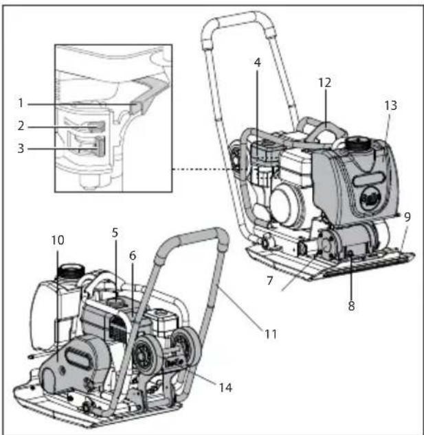
Machine Description

text_image
Technical diagram of a mechanical device with numbered parts, including a close-up inset view of the internal structure.- Throttle Lever,
- Choke Lever,
- Fuel ON/OFF Lever,
- Air Filter Housing,
- Fuel Tank,
- Exhaust,
- Vibrator Unit,
- Vibrator Oil Check Plug,
- Attach Point For Water Spray Bar,
- Belt Guard,
- Control Handle,
- Lifting Frame,
- Water Tank,
- Transporter Attachment
Technical Data

| Model PCX 20A | |
| A - Width (mm) 500 | |
| B - Length - Operation (mm) 940 | |
| C - Height - Operation (mm) 880 | |
| Length - Storage (mm) 1100 | |
| Height - Storage (mm) 625 | |
| Engine Model Honda GX120 | |
| Engine Power (Hp/kW) 4.0/3.0 @ 3600rpm | |
| * Weight (kg) 75 | |
| Vibrator Force (kN) | 11 |
| Frequency (Hz) | 101 |
| Maximum Travel Speed (m/min) | 16.3 |
| Compaction Force (kg/m2) | 420 |
| ** 3 Axis Vibration (m/sec2) | 13.7 |
| Usage Time (Mins) | 16 |
| Sound Power Level (dB(A)) | 105 |
* Weight includes Water Kit and Transporter Attachment. (Items 13 and 14 of Machine Description)
** Minimum level to EN500 Part 4.

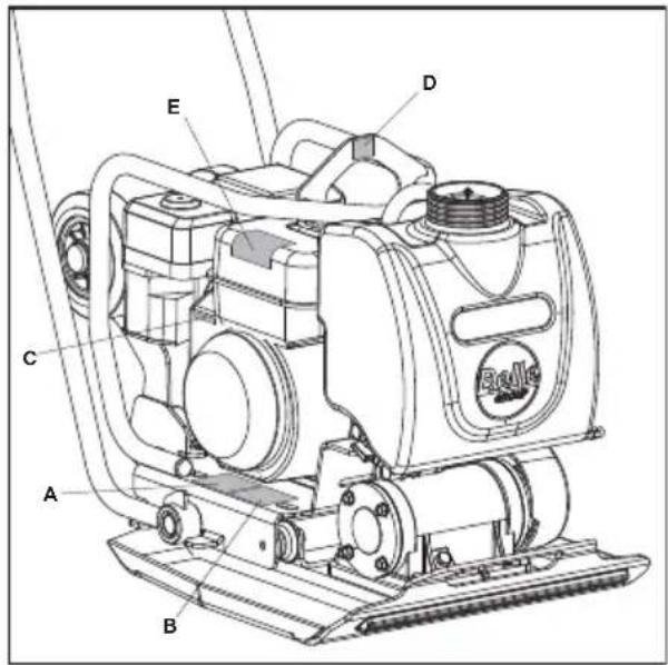
text_image
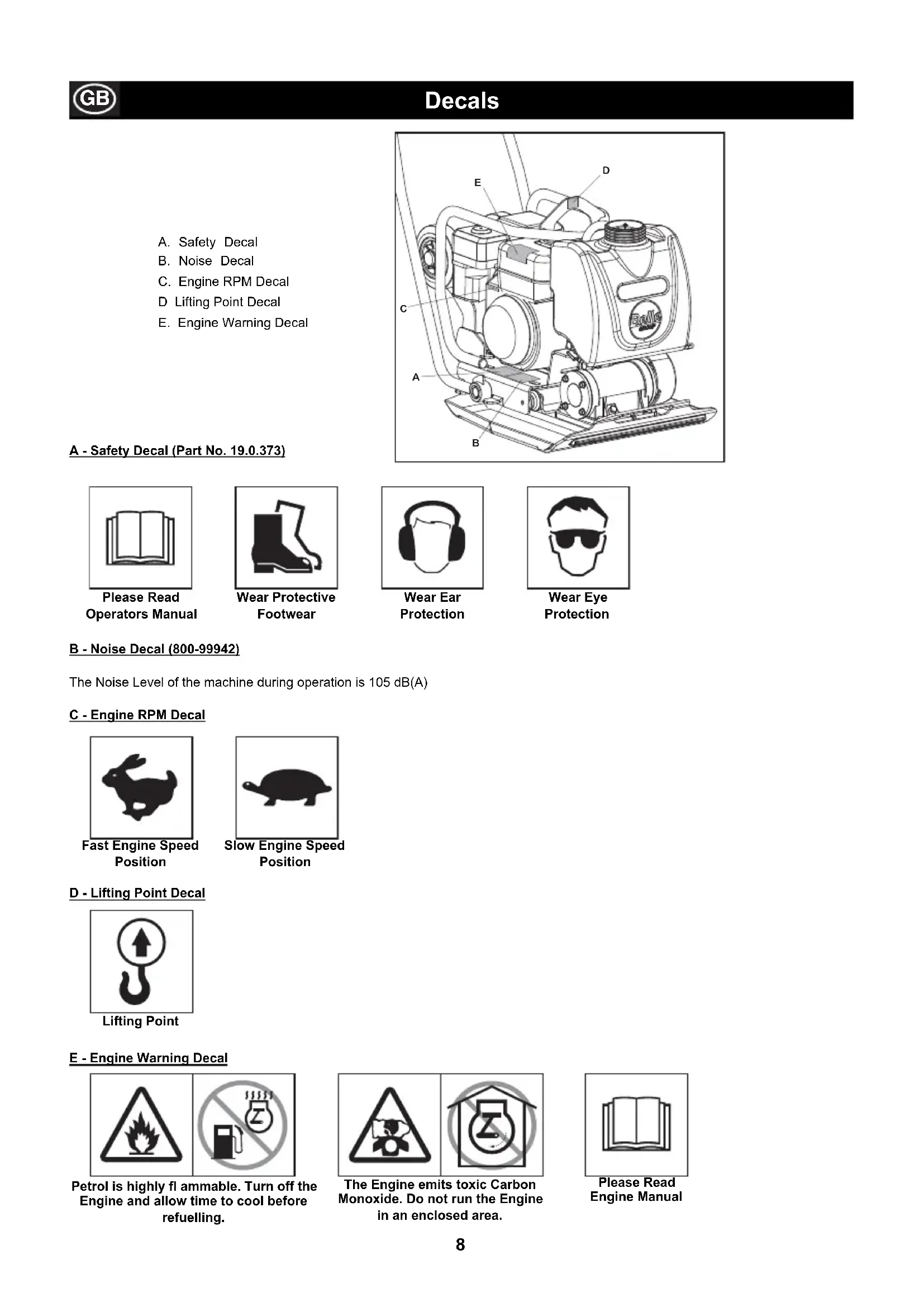
B C AA. Safety Decal
B. Noise Decal
C. Engine RPM Decal
D Lifting Point Decal
E. Engine Warning Decal
text_image
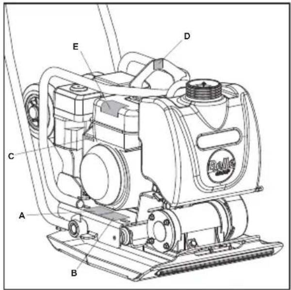
Technical diagram of a mechanical device with labeled parts A through E, including a 'Roller' component.A - Safety Decal (Part No. 19.0.373)

Please Read
Operators Manual

Wear Protective
Footwear

Wear Ear Protection

Wear Eye Protection
B - Noise Decal (800-99942)
The Noise Level of the machine during operation is 105 dB(A)
C - Engine RPM Decal

Fast Engine Speed Position

Slow Engine Speed Position
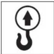
D - Lifting Point Decal

Lifting Point
E - Engine Warning Decal

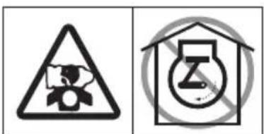
text_image
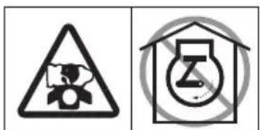
Two safety symbols: a triangular warning triangle with flame and smoke, and a prohibition sign for fuel pump.Petrol is highly fl ammable. Turn off the Engine and allow time to cool before refuelling.

text_image
Two safety symbols: a triangular warning triangle with a gear icon and a house with a circular symbol containing a letter 'Z'.The Engine emits toxic Carbon Monoxide. Do not run the Engine in an enclosed area.

Please Read
Engine Manual
Environment
Safe Disposal.

Instructions for the protection of the environment. The machine contains valuable materials. Take the discarded apparatus and accessories to the relevant recycling facilities.
| Component | Material |
| Operator Handle Steel | |
| Base Plate Steel | |
| Eccentric weights Steel | |
| Petrol engine housing Aluminium | |
| Petrol engine covers Synthetic material | |
| Various parts Steel & Aluminium |
Reasons For Compaction

Soil, which has been disturbed or new infill, subbase and blacktop, will have small voids or air pockets which, if not compacted, will lead to one or more problems occurring.
- As traffic crosses the surface of an uncompacted area, the material is compressed. This leads to subsidence of the top surface as the material fills the voids.
- A similar situation occurs with static loads on uncompacted ground. The load (e.g. a building) will sink.
- Materials with voids are more susceptible to water seepage, leading to erosion. Water ingress may also cause the soil to expand during freezing temperatures and contract during dry spells. Expansion and contraction is a major cause of damage to building foundations and normally leads to the structure requiring underpinning.
Compaction increases the density of the material and therefore increases its load bearing capacity. Reduces air voids and therefore reduces the risk of subsidence, expansion and contraction, due to ingress of water.
Safety Instructions

For your own personal protection and for the safety of those around you, please read and ensure you fully understand the following safety information. It is the responsibility of the operator to ensure that he/she fully understands how to operate this equipment safely. If you are unsure about the safe and correct use of the 'PCX 20A' Plate compactor, consult your supervisor or Belle Group.

CAUTION
Improper maintenance can be hazardous. Read and Understand this section before you perform any maintenance, service or repairs.
- This equipment is heavy and must not be lifted single-handedly, either GET HELP or use suitable lifting equipment.
• Cordon off the work area and keep members of the public and unauthorized personnel at a safe distance.
• Personal Protective Equipment (PPE) must be worn by the operator whenever this equipment is being used (see Health & Safety).
• Make sure you know how to safely switch this machine OFF before you switch it ON in case you get into difficulty.
• Always switch OFF the engine before transporting, moving it around the site or servicing it. - During use the engine becomes very hot, allow the engine to cool before touching it. Never leave the engine running and unattended.
- Never remove or tamper with any guards fitted, they are there for your protection. Always check guards for condition and security, if any are damaged or missing, DO NOT USE THE MACHINE until the guard has been replaced or repaired.
- Do not operate the MACHINE when you are ill, feeling tired, or when under the influence of alcohol or drugs.

CAUTION
Fuel is flammable. It may cause injury and property damage. Shut down the engine, extinguish all open flames and do not smoke while fi lling the fuel tank. Always wipe up any spilled fuel.
Fuel Safety.
- Before refuelling, switch off the engine and allow it to cool.
- When refuelling, DO NOT smoke or allow naked flames in the area.
- Spilt fuel must be made safe immediately, using sand. If fuel is spilt on your clothes, change them.
- Store fuel in an approved, purpose made container away from heat and ignition sources.
Vibration
Some vibration from the trowelling operation is transmitted through the handle to the operator's hands. Refer to specifications & technical data for vibration levels and usage times (recommended maximum daily exposure time). DO NOT exceed the maximum usage times.
PPE (Personal Protective Equipment).
Suitable PPE must be worn when using this equipment i.e. Safety Goggles, Gloves, Ear Defenders, Dust Mask and Steel Toe capped footwear (with anti-slip soles for added protection). Wear clothing suitable for the work you are doing. Always protect skin from contact with concrete.
Dust.
The compaction process can produce dust, which may be hazardous to your health. Always wear a mask that is suited to the type of dust being produced.
Fuel.
Do not ingest fuel or inhale fuel vapors and avoid contact with your skin. Wash fuel splashes immediately. If you get fuel in your eyes, irrigate with copious amounts of water and seek medical attention as soon as possible.
Exhaust Fumes.
Do not operate your 'PCX 20A' indoors or in a confined space, make sure the work area is adequately ventilated.

WARNING
The exhaust fumes produced by this equipment are highly toxic and can kill!

Pre-start Checks
Pre start-up inspection.
The following Pre-start-up inspection must be performed before the start of each work session or after every four hours of use, whichever is first. Please refer to the service section for detailed guidance. If any fault is discovered, the 'PCX 20A' must not be used until the fault is rectified.
- Thoroughly inspect the 'PCX 20A' for signs of damage. Make sure that the belt guard is secure before using the machine.
- Check hoses, filler openings, drain plugs and any other areas for signs of leakage. Fix any leaks before operating.
- Check the engine oil level and top up as necessary.
- Check the engine fuel level and top up as necessary.
- Check for fuel and oil leaks.

Operating Instructions
• Take the compactor to where it is required.
Where it is necessary to use lifting equipment to position the 'PCX 20A', make sure the lifting equipment has a WLL (Working Load Limit) suitable for the 'PCX 20A's weight (see Technical Data section or machine serial plate). Attach suitable chains or slings ONLY to the lifting point on the top of the 'PCX 20A'.
- NEVER leave the engine running whilst transporting or moving the 'PCX 20A', even if it is only a short distance.
- Having carried out the checks listed in the 'pre start' section, you may start the engine.
The Belle Group 'PCX 20A' range of compactors are fitted with a centrifugal clutch, this allows the engine to run at idle without driving the vibrator. As the engine speed is increased the clutch will engage and will drive the vibrator. For correct operation, the engine speed should be set to maximum.
- Set the throttle to maximum and use the control handle to steer or turn the 'PCX 20A'.
The vibrator will not only cause the baseplate to vibrate but will also cause it to travel forward. During normal operation you should not have to push the 'PCX 20A' but allow it to travel at its own pace. The speed of travel will be determined by the condition of the surface being compacted. If the surface to be compacted is on a slope, great care must be taken when controlling the 'PCX 20A's direction of travel. If necessary, use a suitable rope attached to the 'PCX 20A' at a low point on the chassis, to allow a helper to take part of the 'PCX 20A's weight. Work up and down a slope not across.
• Work the 'PCX 20A' over the surface in an organized pattern until the required compaction has been achieved.
Where there are a number of different layers to be compacted on top of each other, compact each layer individually.
Operating Instructions

WARNING
Before you operate or carry out any maintenance on this machine YOU MUST READ and STUDY this manual.
Honda GX120
- Open the fuel tap by moving the fuel ON / OFF lever fully to the right.
- If starting the engine from cold, set the choke ON by moving the choke lever fully to the left. If restarting a warm engine, the choke is usually not required, however, if the engine has cooled to a degree, partial choke may be required.
- Turn the engine ON / OFF switch clockwise to the 'I' position.
- Set the throttle to the idle position by moving the throttle lever fully to the right. Do not start the engine on full throttle, as the compactor will vibrate as soon as the engine starts.
-
Taking a firm hold of the control handle with one hand, grasp the recoil starter handle with the other. Pull the recoil starter until engine resistance is felt, then let starter return.
-
Taking care not to pull the starter's rope fully out, pull the starter handle briskly.
-
Repeat until the engine fi res.
-
Once the engine fi res gradually set the choke lever to the OFF position by moving it to the right.
-
If the engine fails to fire after several attempts, follow the trouble-shooting guide on page 6.
-
To stop the engine, set the throttle to idle and turn the engine ON / OFF switch anticlockwise to the '0' position.
-
Turn the fuel off.

text_image
Throttle Choke Fuel ON/OFF LeverTroubleshooting Guide

| Problem Cause Remedy | ||
| Engine will not start. No fuel. Fill fuel tank. | Open fuel tap. | |
| Engine switched off. Switch Spark plug fouled. Clean Engine cold. Close choke. | ch engine on. | |
| and reset plug gap. | ||
| Engine flooded. Open choke, fully open throttle, pull recoil starter until engine fi res. | ||
| Engine still will not start Unit will not vibrate. | Major Fault | Contact Agent or Belle Group. |
| Engine speed too slow. | Set engine speed control to fast. | |
| Drive belt tension loose. Air fi Iter blocked. | Adjust belt tension | |
| Clean or renew air fi Iter. | ||
| Drive failure. Vibrator failure. | Contact Agent or Belle Group. | |
| Contact Agent or Belle Group. | ||
| Asphalt adhering to plate. Bituminous surface fl aking (laminating). | Lack of lubrication. | Use water |
| Over compaction. | Remove and relay. | |
| Low travel speed (plate sinking). | Layer thickness too deep. | Remove some of the material. |
| Moisture content too high or too low. | Remove material and adjust. | |
Maintenance
The Belle Group 'PCX 20A' range is designed to give many years of trouble free operation. It is recommended that an approved Belle Group dealer carries out all major maintenance and repairs. Always use genuine Belle Group replacement parts, the use of spurious parts may void your warranty.
Before any maintenance is carried out on the machine, switch off the engine and disconnect the HT lead from the sparkplug.
Always set the 'PCX 20A' on level ground to ensure any fluid levels will be correctly read. Only use recommended oils (see chart on following page).
Running In Period
When the 'PCX 20A' is first used from new, the engine oil must be changed after the initial running in period (see engine manual for full detail). The vibrator shaft case oil must be replaced after the first 100 hours use, then after every 500 working hours. For detail on vibrator shaft case oil replacement, see 'Vibrator unit'.
The belt tension should be checked after 4 hours use.
| Routine Maintenance After First First month / 3 Months 6 months4 hours 20Hours 50 Hours 100 Hours | |||||
| Engine Oil Check Level | √ | ||||
| Change | √ | √ | |||
| Air Filter | Check Condition | √ | √ | ||
| Clean / Replace | √ | ||||
| Spark Plug | Check / Clean | √ | |||
| Drive Belt | Tension | √ | √ | √ | |
Oil / Fuel Type & Quantity - Spark Plug Type
| Oil type | Quantity (Litre) | Fuel Type | Capacity (Litre) | Spark Plug Type | Electrode Gap (mm) | |
| Petrol Honda GX120 | S.A.E. 10W 30 | 0.6 | Unleaded | 2.5 | BM6ES or BPR6ES | 0.7 - 0.8 |
| Vibrator | Turbine Oil 32 | 0.22 | N/A | N/A | N/A | N/A |
text_image
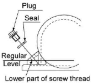
Plug Seal Regular Level Lower part of screw threadVibrator Unit.
Remove the plug complete with seal, check that the oil level reaches the bottom thread on the oil plug hole. Top up as necessary with the correct oil (see chart).

text_image
1. M10 Bolts and Washers
text_image
2. M10 Bolts and Washers- Unscrew the 2 x M10 Bolts to a height of 15mm, then lift the M10 Flat and Spring Washer to the head of the Bolts (See Image 1)
- Line the slots in the Wheel Kit with the M10 Bolts.
- Slide the Wheel Kit into place. Take care to push it on until the Bolts make contact with the bottom of the slot and cannot be pushed on any further.
- Release the M10 Flat and Spring Washers so that they sit on top of the Wheel Kit. They should now be visible to the operator.
- Re-tighten the M10 Bolts to a Torque Setting of 55Nm.
Warranty

Your new Belle Group 'PCX 20A' single direction plate compactor is warranted to the original purchaser for a period of one-year (12 months) from the original date of purchase. The Belle Group warranty is against defects in design, materials and workmanship.
The following are not covered under the Belle Group warranty:
- Damage caused by abuse, misuse, dropping or other similar damage caused by or as a result of failure to follow assembly, operation or user maintenance instructions.
- Alterations, additions or repairs carried out by persons other than Belle Group or their recognised agents.
- Transportation or shipment costs to and from Belle Group or their recognised agents, for repair or assessment against a warranty claim, on any machine.
- Materials and/or labour costs to renew, repair or replace components due to fair wear and tear.
The following components are not covered by warranty.
Drivebelt/s
· Engine air fi Iter
· Engine spark plug
Belle Group and/or their recognised agents, directors, employees or insurers will not be held liable for consequential or other damages, losses or expenses in connection with or by reason of or the inability to use the machine for any purpose.
Warranty Claims
All warranty claims should firstly be directed to Belle Group, either by telephone, by Fax, by Email, or in writing.
For warranty claims:
Tel: +44 (0)1298 84606 Fax: +44 (0)1298 84722 Email : Warranty@belle-group.co.uk
Write to:
Belle Group Warranty Department,
Sheen, Nr. Buxton,
Derbyshire
SK17 0EU
England.
This manual has been written to help you operate and service the 'PCX 20A' Plate compactor safely. This manual is intended for dealers and operators of the 'PCX 20A' Plate compactor.
Foreword
The ‘Machine Description’ section helps you to familiarise yourself with the machine's layout and controls.
The 'Environment' section gives instructions on how to handle the recycling of discarded apparatus in an environmentally friendly way.
The ‘General Safety’ and ‘Health and Safety’ sections explain how to use the machine to ensure your safety and the safety of the general public.
The 'Operating Instructions' section helps you with the setting up and use of the machine.
The 'Trouble Shooting' guide helps you if you have a problem with your machine.
The 'Service & Maintenance' section is to help you with the general maintenance and servicing of your machine.
The 'Warranty' Section details the nature of the warranty cover and the claims procedure.
Directives with regard to the notations.
Text in this manual to which special attention must be paid are shown in the following way:

CAUTION
The product can be at risk. The machine or yourself can be damaged or injured if procedures are not carried out in the correct way.

WARNING
The life of the operator can be at risk.

WARNING

WARNING
Before you operate or carry out any maintenance on this machine YOU MUST READ and STUDY this manual.
KNOW how to safely use the unit's controls and what you must do for safe maintenance. (NB Be sure that you know how to switch the machine off before you switch on, in case you get into diffi culty.)
ALWAYS wear or use the proper safety items required for your personal protection. If you have ANY QUESTIONS about the safe use or maintenance of this unit, ASK YOUR SUPERVISOR OR CONTACT: BELLE GROUP (UK): +44 (0) 1298 84606

Contents
How to use this manual....14
Warning 14
Machine Description....15
Technical Data....15
Decals....16
Environment 17
Reasons For compaction ....17
Safety Instructions....17
Health and Safety....18
Pre-Start Checks 18
Operating Instructions 18 - 19
Trouble Shooting Guide 19
Service & Maintenance 20
Fitting Instructions....21
Warranty 21
Machine Description
text_image
Technical diagram of a mechanical device with numbered parts, including front view and side views with Chinese labels.- Throttle Lever,
- Choke Lever,
- Fuel ON/OFF Lever,
- Air Filter Housing,
- Fuel Tank,
- Exhaust,
- Vibrator Unit,
- Vibrator Oil Check Plug,
- Attach Point For Water Spray Bar,
- Belt Guard,
- Control Handle,
- Lifting Frame,
- Water Tank,
- Transporter Attachment
Technical Data

| Model | PCX |
| A - Width (in) 19.7 | |
| B - Length - Operation (in) 37.0 | |
| C - Height - Operation (in) 34.6 | |
| Length - Storage (in) 43.3 | |
| Height - Storage (in) 24.6 | |
| Engine Model Honda GX120 | |
| Engine Power (Hp/kW) 4.0/3.0 @ 3600rpm | |
| * Weight (lbs) 165.3 | |
| Vibrator Force (kN) | 11 |
| Frequency (Hz) | 101 |
| Maximum Travel Speed (ft/min) | 53.5 |
| Compaction Force (lbs/m2) | 926 |
| ** 3 Axis Vibration (m/sec2) | 13.7 |
| Usage Time (Mins) | 16 |
| Sound Power Level (dB(A)) | 105 |
* Weight includes Water Kit and Transporter Attachment. (Items 13 and 14 of Machine Description)
** Minimum level to EN500 Part 4.

text_image
B C AA. Safety Decal
B. Noise Decal
C. Engine RPM Decal
D Lifting Point Decal
E. Engine Warning Decal
text_image
Technical diagram of a mechanical device with labeled parts A through E, including a Bollie brand logo.A - Safety Decal (Part No. 19.0.373)

Please Read
Operators Manual

Wear Protective
Footwear

Wear Ear Protection

Wear Eye Protection
B - Noise Decal (800-99942)
The Noise Level of the machine during operation is 105 dB(A)
C - Engine RPM Decal

Fast Engine Speed Position

Slow Engine Speed Position
D - Lifting Point Decal
Lifting Point
E - Engine Warning Decal

text_image
Two safety symbols: a triangular warning triangle with flame and a prohibition sign for fuel pump.Petrol is highly fl ammable. Turn off the Engine and allow time to cool before refuelling.
text_image
Two safety symbols: a triangular warning triangle with a gear icon and a house with a circular symbol containing a letter 'Z'.The Engine emits toxic Carbon Monoxide. Do not run the Engine in an enclosed area.

Please Read
Engine Manual
Environment

Safe Disposal.

Instructions for the protection of the environment. The machine contains valuable materials. Take the discarded apparatus and accessories to the relevant recycling facilities.
| Component | Material |
| Operator Handle Steel | |
| Base Plate Steel | |
| Eccentric weights Steel | |
| Petrol engine housing Aluminium | |
| Petrol engine covers Synthetic material | |
| Various parts Steel & Aluminium |
Reasons For Compaction

Soil, which has been disturbed or new infill, subbase and blacktop, will have small voids or air pockets which, if not compacted, will lead to one or more problems occurring.
- As traffic crosses the surface of an uncompacted area, the material is compressed. This leads to subsidence of the top surface as the material fills the voids.
- A similar situation occurs with static loads on uncompacted ground. The load (e.g. a building) will sink.
- Materials with voids are more susceptible to water seepage, leading to erosion. Water ingress may also cause the soil to expand during freezing temperatures and contract during dry spells. Expansion and contraction is a major cause of damage to building foundations and normally leads to the structure requiring underpinning.
Compaction increases the density of the material and therefore increases its load bearing capacity. Reduces air voids and therefore reduces the risk of subsidence, expansion and contraction, due to ingress of water.
Safety Instructions

For your own personal protection and for the safety of those around you, please read and ensure you fully understand the following safety information. It is the responsibility of the operator to ensure that he/she fully understands how to operate this equipment safely. If you are unsure about the safe and correct use of the 'PCX 20A' Plate compactor, consult your supervisor or Belle Group.

CAUTION
Improper maintenance can be hazardous. Read and Understand this section before you perform any maintenance, service or repairs.
- This equipment is heavy and must not be lifted single-handedly, either GET HELP or use suitable lifting equipment.
• Cordon off the work area and keep members of the public and unauthorized personnel at a safe distance.
• Personal Protective Equipment (PPE) must be worn by the operator whenever this equipment is being used (see Health & Safety).
• Make sure you know how to safely switch this machine OFF before you switch it ON in case you get into diffi culty. - Always switch OFF the engine before transporting, moving it around the site or servicing it.
- During use the engine becomes very hot, allow the engine to cool before touching it. Never leave the engine running and unattended.
- Never remove or tamper with any guards fitted, they are there for your protection. Always check guards for condition and security, if any are damaged or missing, DO NOT USE THE MACHINE until the guard has been replaced or repaired.
- Do not operate the MACHINE when you are ill, feeling tired, or when under the influence of alcohol or drugs.

CAUTION
Fuel is flammable. It may cause injury and property damage. Shut down the engine, extinguish all open fl ames and do not smoke while fi lling the fuel tank. Always wipe up any spilled fuel.
Fuel Safety.
- Before refuelling, switch off the engine and allow it to cool.
- When refuelling, DO NOT smoke or allow naked flames in the area.
- Spilt fuel must be made safe immediately, using sand. If fuel is spilt on your clothes, change them.
- Store fuel in an approved, purpose made container away from heat and ignition sources.
Vibration
Some vibration from the trowelling operation is transmitted through the handle to the operator's hands. Refer to specifications & technical data for vibration levels and usage times (recommended maximum daily exposure time). DO NOT exceed the maximum usage times.
PPE (Personal Protective Equipment).
Suitable PPE must be worn when using this equipment i.e. Safety Goggles, Gloves, Ear Defenders, Dust Mask and Steel Toe capped footwear (with anti-slip soles for added protection). Wear clothing suitable for the work you are doing. Always protect skin from contact with concrete.
Dust.
The compaction process can produce dust, which may be hazardous to your health. Always wear a mask that is suited to the type of dust being produced.
Fuel.
Do not ingest fuel or inhale fuel vapors and avoid contact with your skin. Wash fuel splashes immediately. If you get fuel in your eyes, irrigate with copious amounts of water and seek medical attention as soon as possible.
Exhaust Fumes.
Do not operate your 'PCX 20A' indoors or in a confined space, make sure the work area is adequately ventilated.

WARNING
The exhaust fumes produced by this equipment are highly toxic and can kill!

Pre-start Checks
Pre start-up inspection.
The following Pre-start-up inspection must be performed before the start of each work session or after every four hours of use, whichever is first. Please refer to the service section for detailed guidance. If any fault is discovered, the 'PCX 20A' must not be used until the fault is rectified.
- Thoroughly inspect the 'PCX 20A' for signs of damage. Make sure that the belt guard is secure before using the machine.
- Check hoses, filler openings, drain plugs and any other areas for signs of leakage. Fix any leaks before operating.
- Check the engine oil level and top up as necessary.
- Check the engine fuel level and top up as necessary.
- Check for fuel and oil leaks.

Operating Instructions
• Take the compactor to where it is required.
Where it is necessary to use lifting equipment to position the 'PCX 20A', make sure the lifting equipment has a WLL (Working Load Limit) suitable for the 'PCX 20A's weight (see Technical Data section or machine serial plate). Attach suitable chains or slings ONLY to the lifting point on the top of the 'PCX 20A'.
- NEVER leave the engine running whilst transporting or moving the 'PCX 20A', even if it is only a short distance.
- Having carried out the checks listed in the 'pre start' section, you may start the engine.
The Belle Group 'PCX 20A' range of compactors are fitted with a centrifugal clutch, this allows the engine to run at idle without driving the vibrator. As the engine speed is increased the clutch will engage and will drive the vibrator. For correct operation, the engine speed should be set to maximum.
- Set the throttle to maximum and use the control handle to steer or turn the 'PCX 20A'.
The vibrator will not only cause the baseplate to vibrate but will also cause it to travel forward. During normal operation you should not have to push the 'PCX 20A' but allow it to travel at its own pace. The speed of travel will be determined by the condition of the surface being compacted. If the surface to be compacted is on a slope, great care must be taken when controlling the 'PCX 20A's direction of travel. If necessary, use a suitable rope attached to the 'PCX 20A' at a low point on the chassis, to allow a helper to take part of the 'PCX 20A's weight. Work up and down a slope not across.
• Work the 'PCX 20A' over the surface in an organized pattern until the required compaction has been achieved.
Where there are a number of different layers to be compacted on top of each other, compact each layer individually.
Operating Instructions

WARNING
Before you operate or carry out any maintenance on this machine YOU MUST READ and STUDY this manual.
Honda GX120
- Open the fuel tap by moving the fuel ON / OFF lever fully to the right.
- If starting the engine from cold, set the choke ON by moving the choke lever fully to the left. If restarting a warm engine, the choke is usually not required, however, if the engine has cooled to a degree, partial choke may be required.
- Turn the engine ON / OFF switch clockwise to the 'I' position.
- Set the throttle to the idle position by moving the throttle lever fully to the right. Do not start the engine on full throttle, as the compactor will vibrate as soon as the engine starts.
-
Taking a firm hold of the control handle with one hand, grasp the recoil starter handle with the other. Pull the recoil starter until engine resistance is felt, then let starter return.
-
Taking care not to pull the starter's rope fully out, pull the starter handle briskly.
-
Repeat until the engine fi res.
-
Once the engine fi res gradually set the choke lever to the OFF position by moving it to the right.
-
If the engine fails to fire after several attempts, follow the trouble-shooting guide on page 13.
-
To stop the engine, set the throttle to idle and turn the engine ON / OFF switch anticlockwise to the '0' position.
-
Turn the fuel off.

text_image
Throttle Choke Fuel ON/OFF LeverTroubleshooting Guide

| Problem Cause Remedy | ||
| Engine will not start. No fuelFill fuel tank.Engine switched off. SwitchSpark plug fouled. CleanEngine cold. Close choke. | Open fuel tap. | |
| ch engine on. | ||
| and reset plug gap. | ||
| Engine flooded. | Open choke, fully open throttle, pull recoil starter until engine fi res. | |
| Engine still will not startUnit will not vibrate.Drive belt tension loose.Air fi lter blocked.Drive failure.Vibrator failure. | Major Fault | Contact Agent or Belle Group. |
| Engine speed too slow. | Set engine speed control to fast. | |
| Adjust belt tension | ||
| Clean or renew air fi lter. | ||
| Contact Agent or Belle Group. | ||
| Contact Agent or Belle Group. | ||
| Asphalt adhering to plate.Bituminous surfacefl aking (laminating). | Lack of lubrication. | Use water |
| Over compaction. | Remove and relay. | |
| Low travel speed(plate sinking). | Layer thickness too deep. | Remove some of the material. |
| Moisture content too high or too low. | Remove material and adjust. | |
Maintenance
The Belle Group 'PCX 20A' range is designed to give many years of trouble free operation. It is recommended that an approved Belle Group dealer carries out all major maintenance and repairs. Always use genuine Belle Group replacement parts, the use of spurious parts may void your warranty.
Before any maintenance is carried out on the machine, switch off the engine and disconnect the HT lead from the sparkplug.
Always set the 'PCX 20A' on level ground to ensure any fluid levels will be correctly read. Only use recommended oils (see chart on following page).
Running In Period
When the 'PCX 20A' is first used from new, the engine oil must be changed after the initial running in period (see engine manual for full detail). The vibrator shaft case oil must be replaced after the first 100 hours use, then after every 500 working hours. For detail on vibrator shaft case oil replacement, see 'Vibrator unit'.
The belt tension should be checked after 4 hours use.
| Routine Maintenance After First First month / 3 Months 6 months4 hours 20Hours 50 Hours 100 Hours | |||||
| Engine Oil Check Level | √ | ||||
| Change | √ | √ | |||
| Air Filter | Check Condition | √ | √ | ||
| Clean / Replace | √ | ||||
| Spark Plug | Check / Clean | √ | |||
| Drive Belt | Tension | √ | √ | √ | |
Oil / Fuel Type & Quantity - Spark Plug Type
| Oil type | Quantity (Gals) | Fuel Type | Capacity (Gals) | Spark Plug Type | Electrode Gap (mm) | |
| Petrol Honda GX120 | S.A.E. 10W 30 | 0.16 | Unleaded | 0.66 | BM6ES or BPR6ES | 0.7 - 0.8 |
| Vibrator | Turbine Oil 32 | 0.06 | N/A | N/A | N/A | N/A |

text_image
Plug Seal Regular Level Lower part of screw threadVibrator Unit.
Remove the plug complete with seal, check that the oil level reaches the bottom thread on the oil plug hole. Top up as necessary with the correct oil (see chart).

text_image
1. M10 Bolts and Washers 2. M10 Bolts and Washers- Unscrew the 2 x M10 Bolts to a height of 15mm, then lift the M10 Flat and Spring Washer to the head of the Bolts (See Image 1)
- Line the slots in the Wheel Kit with the M10 Bolts.
- Slide the Wheel Kit into place. Take care to push it on until the Bolts make contact with the bottom of the slot and cannot be pushed on any further.
- Release the M10 Flat and Spring Washers so that they sit on top of the Wheel Kit. They should now be visible to the operator.
- Re-tighten the M10 Bolts to a Torque Setting of 55Nm.
Warranty

Your new Belle Group 'PCX 20A' single direction plate compactor is warranted to the original purchaser for a period of one-year (12 months) from the original date of purchase. The Belle Group warranty is against defects in design, materials and workmanship.
The following are not covered under the Belle Group warranty:
- Damage caused by abuse, misuse, dropping or other similar damage caused by or as a result of failure to follow assembly, operation or user maintenance instructions.
- Alterations, additions or repairs carried out by persons other than Belle Group or their recognised agents.
- Transportation or shipment costs to and from Belle Group or their recognised agents, for repair or assessment against a warranty claim, on any machine.
- Materials and/or labour costs to renew, repair or replace components due to fair wear and tear.
The following components are not covered by warranty.
Drivebelt/s
· Engine air fi Iter
- Engine spark plug
Belle Group and/or their recognised agents, directors, employees or insurers will not be held liable for consequential or other damages, losses or expenses in connection with or by reason of or the inability to use the machine for any purpose.
Warranty Claims
All warranty claims should firstly be directed to Belle Group, either by telephone, by Fax, by Email, or in writing.
For warranty claims:
Tel: +1 540.345.5090 Fax: +1 540.345.5090 Email : Sales@BelleGroup.net
Write to:
Belle Group Inc,
3959 Electric Road,
Roanoke, Suite 360,
VA, 24018,
USA
text_image
Technical diagram of a mechanical device with numbered parts, including a close-up inset showing internal components.text_image
Technical diagram of a mechanical device with labeled parts A through E, including Roller and fan components.text_image
Two safety symbols: a triangular warning triangle with flame and smoke, and a crossed-out prohibition sign with a megaphone and smoke.text_image
Two safety symbols: a triangular warning triangle with a gear icon and a circular symbol with a letter 'Z' inside a house.Belle Group Warranty Department,
Sheen, Nr. Buxton,
Derbyshire
SK17 0EU
Angleterre
text_image
Technical diagram of a mechanical device with numbered parts, including a close-up inset view of the engine compartment.text_image
Technical diagram of a mechanical device with labeled parts A through E, including Roller and fan basetext_image
Two safety symbols: a triangular warning triangle with flame and smoke, and a prohibition sign with a megaphone and a bottle.text_image
Two safety symbols: a triangular warning triangle with gear and a circular symbol with a hammer and sickle.Belle Group Warranty Department,
Sheen, Nr. Buxton,
Derbyshire
SK17 0EU
England
text_image
Technical diagram of a mechanical device with numbered parts, including a close-up inset view of the engine compartment.text_image
Technical diagram of a mechanical device with labeled parts A through E, including Roller and fan basetext_image
Two safety symbols: a triangular warning triangle with flame and smoke, and a prohibition sign with a megaphone and a bottle.text_image
Two safety symbols: a triangular warning triangle and a house with a circular symbol containing the letter 'Z'.natural_image
Technical line drawing of a mechanical assembly with no visible text or symbolsEstrangulador
Crontrolo da Mistura Alavanca Ligado/ Desligado de Combustivel
Belle Group Warranty Department,
Sheen, Nr. Buxton,
Derbyshire
SK17 0EU
England.
Tel: +44 (0)1298 84606 Fax: +44 (0)1298 84722 Email : Warranty@belle-group.co.uk
text_image
Technical diagram of a mechanical device with numbered parts, including exploded view and close-up detail.- Gashendel,
- Choke,
- Brandstof ON/OFF hendel,
- Luchtfi Iter Woning,
- Brandstoftank,
- Uitlaat,
- Trilelement,
- Vibreren Petroleum Sortie Tampon,
- Verknochtheid Top Voor Water Vaporisator Zandbank
- Beschermingsmechanisme,
- Zeggenschap Steel,
- Opheffi ng Raamwindow,
- Waterreservoir,
- Oplegger Verknochtheid
Technische gegevens

text_image
Technical diagram of a mechanical device with labeled parts A through E, including a Bollie brand logo.text_image
Two safety symbols: a triangular warning triangle with flame and smoke, and a prohibition sign with a gas pump and smoke.text_image
Two safety symbols: a triangular warning triangle with a gear icon and a circular symbol with a 'Z' inside a house.Belle Group Warranty Department,
Sheen, Nr. Buxton,
Derbyshire
SK17 0EU
England.
text_image
Technical diagram of a mechanical device with numbered parts, including a close-up inset view of the internal structure.text_image
Technical diagram of a mechanical device with labeled parts A through E, including a 'Roller' branding.text_image
Two safety symbols: a triangular warning triangle with flame and smoke, and a prohibition sign for fuel pump and a smokestack.text_image
Two safety symbols: a triangular warning triangle with a gear icon and a circular symbol with a 'Z' inside a house.Belle Group Warranty Department,
Sheen, Nr. Buxton,
Derbyshire
SK17 0EU
England.
text_image
Technical diagram of a lawn mower with numbered components and an inset view of the engine compartmenttext_image
Technical diagram of a mechanical device with labeled parts A through E, including Roller and fan basetext_image
Two safety symbols: a triangular warning triangle with flame and smoke, and a crossed-out prohibition sign with a megaphone and a bottle labeled 'Z'.text_image
Two safety symbols: a triangular warning triangle with a gear and a house with a gear and a letter 'Z' inside.Belle Group Warranty Department,
Sheen, Nr. Buxton,
Derbyshire
SK17 0EU
England.
I
text_image
Technical diagram of a mechanical device with numbered parts, including a close-up inset showing internal components.text_image
Technical diagram of a mechanical device with labeled parts A through E, including a 'Roller' branding.text_image
Warning sign showing a flame symbol and a no-smoking symbol with a megaphonetext_image
Two safety symbols: a triangular warning triangle with a gear icon and a circular symbol with a hammer and sickle.Belle Group Warranty Department,
Sheen, Nr. Buxton,
Derbyshire
SK17 0EU
Inghilterra
text_image
Technical diagram of a mechanical device with numbered components and an inset view of the internal structure.text_image
Technical diagram of a mechanical device with labeled parts A through E, including a 'Roller' branding.Belle Group Warranty Department,
Sheen, Nr. Buxton,
Derbyshire
SK17 0EU
England.
text_image
Technical diagram of a mechanical device with numbered parts, including a close-up inset showing internal components.- Gasshåndtak,
- Choke-håndtak,
- Drivstoffets AV-/PÅ-håndtak,
- Luftfi lterhylse,
- Drivstofftank,
- Eksos,
- Vibrator,
- Vibratorens oljekontrollplugg,
- Vannoverrislingsventilens festepunkt System,
- Reimvern,
- Betjeningshändtak,
- Løftepunk,
- Vannbeholder,
- Transportfeste
Tekniske data

text_image
Technical diagram of a mechanical device with labeled parts A through E, including a 'Roller' branding.A - Sikkerhetsmerke (Del nr. 19.0.373)

Les
driftshåndboka
text_image
Throttle Choke Fuel ON/OFF LeverFeilsøkingsguide

Belle Group Warranty Department /Garantiavdelingen i Belle Group/ Sheen, Nr. Buxton,
Derbyshire
SK17 0EU
England.
UK
text_image
Technical diagram of a mechanical device with numbered parts, including a close-up inset showing internal components.text_image
Technical diagram of a mechanical pump or lift with labeled components A, B, C, D, EBelle Group Warranty Department,
Sheen, Nr. Buxton,
Derbyshire
SK17 0EU
England.
text_image
Technical diagram of a mechanical device with numbered components and an inset view of the engine compartmenttext_image
Technical diagram of a mechanical device with labeled parts A through E, including a roller and fan assembly.text_image
Two safety symbols: a triangular warning triangle with flame and smoke, and a prohibition sign with a bottle and plug.text_image
Two safety symbols: a triangular warning triangle with a gear icon and a circular symbol with a 'Z' inside a house.text_image
Technical diagram of a mechanical device with numbered parts, including front view and exploded view of internal components.text_image
Technical diagram of a mechanical device with labeled parts A through Enatural_image
Silhouette of a rabbit in motion, no text or symbols presentEmail : Warranty@belle-group.co.uk
В письменном виде:
Belle Group Warranty Department,
Sheen, Nr. Buxton,
Derbyshire
SK17 0EU
Англия
text_image
Technical diagram of a mechanical device with numbered parts, including front view and internal components- Drosseli kang,
- Ôhuklapi kang,
- Kütuse etteande avamise/sulgemise (ON/OFF) kang
- Ōhufi ltri korpus,
- Kütusepaak,
- Summuti,
- Vibroseade,
- Vibraatori ölitaseme kontrollkork,
- Veepihusti toru ühenduskoht,
- Rihmakaitse,
- Juhtimislook,
- Tõstmislooka,
- Veepaak,
- Teisaldamiskäru
Masina kirjeldus
EST
text_image
Technical diagram of a mechanical pump or lift system with labeled components A, B, C, D, EA - Ohutuskleeps (varuosa nr 19.0.373)

Lugege
kasutusjuhendit

Kandke
turvajalatseid
natural_image
Technical line drawing of a mechanical component with no visible text or symbolsBelle Group Warranty Department,
Sheen, Nr. Buxton,
Derbyshire
SK17 0EU
England.
Fitting Instructions....133
Garantija....133
CE sertifikāts....4

text_image
Technical diagram of a mechanical device with numbered parts, including front view and side views with Chinese labels.text_image
Technical diagram of a mechanical pump or lift with labeled components A, B, C, D, Enatural_image
Technical line drawing of a mechanical assembly with no visible text or symbolsDegvielas droseles svira
Gaisa droseles svira
Degvielas padeves svira

Bojājumu izlabošana
Belle Group Warranty Department,
Sheen, Nr. Buxton,
Derbyshire
SK17 0EU
England.
text_image
Technical diagram of a mechanical device with numbered parts, including a close-up inset showing internal components.text_image
Technical diagram of a mechanical pump or lift system with labeled components A through Etext_image
Two safety symbols: a triangular warning triangle with flame and smoke, and a prohibition sign with a megaphone and a bottle.text_image
Two safety symbols: a triangular warning triangle with a gear icon and a circular symbol with 'Z' inside a house.Belle Group Warranty Department,
Sheen, Nr. Buxton,
Derbyshire
SK17 0EU
England
text_image
Technical diagram of a mechanical device with numbered parts, including a close-up inset showing internal components.text_image
Technical diagram of a mechanical device with labeled parts A through E, including a Bollie brand logo.text_image
Two safety symbols: a triangular warning triangle with flame and smoke, and a prohibition sign with a fuel pump and smoke.text_image
Two safety symbols: a triangular warning triangle with a gear icon and a circular symbol with a 'Z' inside, both without readable text.natural_image
Technical line drawing of a mechanical assembly with no visible text or symbolstext_image
1. M10 Bolts and Washers
text_image
2. M10 Bolts and WashersEmail : Warranty@belle-group.co.uk
Пишете на адрес:
UK: Belle Group Warranty Department,
Belle Group Warranty Department,
Sheen, Nr. Buxton,
Derbyshire
SK17 0EU
England.
text_image
Technical diagram of a mechanical device with numbered parts, including a close-up inset showing internal components.text_image
Technical diagram of a mechanical device with labeled parts A through Etext_image
Warning sign showing a flame symbol and a no-hanging fuel pump with a smokestack icontext_image
Two safety symbols: a triangular warning triangle and a circular symbol with a lightning bolt inside a box.Belle Group Warranty Department,
Sheen, Nr. Buxton,
Derbyshire
SK17 0EU
England.
Tel: +44 (0)1298 84606 Fax: +44 (0)1298 84722 Email : Warranty@belle-group.co.uk
text_image
Technical diagram of a mechanical device with numbered parts, including a close-up inset showing internal components.text_image
Technical diagram of a mechanical device with labeled parts A through E, including a Bollie brand logo.The Noise Level of the machine during operation is 105 dB(A)
text_image
Two safety symbols: a triangular warning triangle with flame and smoke, and a prohibition sign with a megaphone and a bottle.text_image
Two safety symbols: a triangular warning triangle with a gear icon and a circular symbol with a 'Z' inside a house.text_image
Throttle Choke Fuel ON/OFF LeverBelle Group Warranty Department (Departamentul de Garantie Belle Group)
Sheen, Nr. Buxton,
Derbyshire
SK17 0EU
Anglia
text_image
Technical diagram of a mechanical device with numbered parts, including a close-up inset view of the internal structure.text_image
Technical diagram of a mechanical device with labeled parts A through E, including a 'Roller' branding.text_image
Two safety symbols: a triangular warning triangle with flame and smoke, and a prohibition sign with a megaphone and a smokestack.text_image
Two safety symbols: a triangular warning triangle with a gear icon and a circular symbol with a 'Z' inside a house.Belle Group Warranty Department,
Sheen, Nr. Buxton,
Derbyshire
SK17 0EU
England.
Fitting Instructions....181
Garancija 181
text_image
Technical diagram of a mechanical device with numbered parts, including a close-up inset showing internal components.text_image
Technical diagram of a mechanical device with labeled parts A through E, including a Bollie brand logo.A - Natpis za sigurnost (Dio broj 19.0.373)

Molimo pročitajte
priručnik za
rukovatelja
text_image
Warning sign showing a flame symbol and a no-smoking symbol with a lightbulb iconBenzin je vrlo zapaljiv. Ugasite motor i pustite ga neko vrijeme da se ohladi prije dolijevanja goriva.
text_image
Two safety symbols: a triangular warning triangle with a gear icon and a circular symbol with a 'Z' inside a house.Motor emitira otrovni ugljični monoksid. Nemojte paliti motor u zatvorenom prostoru.

Molimo pročitajte
priručnik za motor
Siguarno odlaganje.

text_image
Gas Čok Gorivo ON/OFFBelle Group Warranty Department,
Sheen, Nr. Buxton,
Derbyshire
SK17 0EU
England.
www.Belle247.com
Belle Group Replacement Parts
are now available for purchase online...
24 Hours a Day, 7 Days a Week!

text_image
Belle Customer Belle Group Customer Welcome Welcome start : This is not logged-in: 67.04 on 62.07.2007. Justice Record Feedback for Technical Setup: Testing: (21.04.2007) Price Update The price was $5.00 - (22.04.2007) Martha Text Message This is a short of the year... (23.03.2007) Text Message A message ** You can be able to use online Safety Block Customer Belle Group Belle Group Belle Group Belle Group Belle Group Belle Group Belle Group Belle Group Belle Group Belle Group Belle Group Belle Group Belle Group Belle Group Belle Group Belle Group Belle Group Belle Group Belle Group Belle Group Belle Group Belle Group Belle Group Belle Group Belle Group Belle GROUPE Breaking Moving Generators Before Preparation
text_image
Belle GROUPwww.BelleGroup.com
COMPACTING...
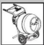
MIXING...

CONCRETING...
No.1 for Light Construction Equipment

CUTTING...
BREAKING...

MOVING
NEW PRODUCT...
Belle Clean
Concrete Dissolver
- No Phosphoric Acid
- Non Corrosive
-
Non Hazardous to Equipment
-
No Hydrochloric Acid
- Non Fuming
- 100% Biodegradable
The Acid Alternative
Use On : Mixers . Trowels . Screeds . Saws .
Pumps. Cement Trucks. Patios.
Wooden Decks. Vehicles & much more

text_image
HELLI CLEAN PROPOSED CLEANER JUN
natural_image
Illustration of a cylindrical scientific instrument mounted on a tripod stand (no text or symbols visible)
natural_image
Exterior view of a gray industrial container with visible branding and branding (no readable text or symbols)
text_image
Belle GROUPBelle Group Head Office
Sheen, Nr. Buxton
Derbyshire
SK17 0EU
Tel: (+44) 01298 84606
Fax: (+44) 01298 84722
Belle Group Parts Centre
Sheen, Nr. Buxton
Derbyshire
SK17 0EU
Tel: (+44) 01298 84606
Fax: (+44) 01298 84722
www.BelleGroup.com

COMPACTING...

MIXING...

CONCRETING...
No.1 for Light Construction Equipment

CUTTING...

BREAKING...

MOVING
text_image
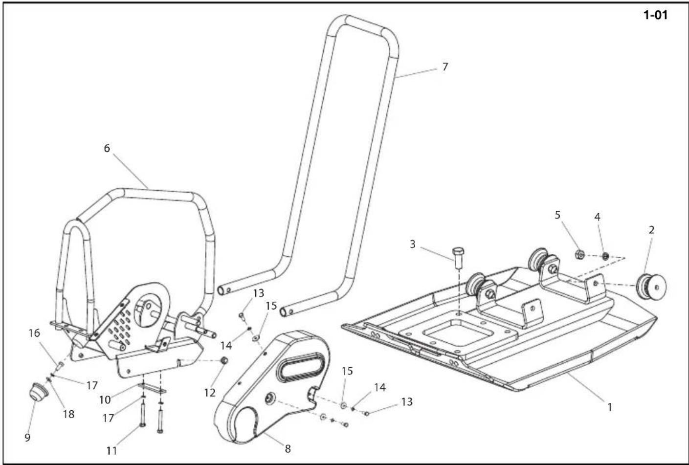
1-01 7 6 13 15 14 12 15 14 13 8 16 17 10 17 18 9 11 3 5 4 2 1Baseplate & Bedplate Assembly, Plaque d'embase & Plaque d'assise, Cto. Placa de Base & Bancada, Conj. da Placa de base & Placa de Apoio —▶1001619
1-01
| 1 | 960/00100 | Baseplate | Plaque d'embase | Placa de base | Placa de Base | 1 |
| 2 | 21.0.298 | Anti-Vibration Mount | Tampon antivibratoire | Montura antivibratoria | Bloco Anti-vibração | 4 |
| 3 | 07.9.062 | Screw | Vis | Tornillo | Parafuse | M14 x 35 |
| 4 | 4/1003 | Washer | Rondelle | Arandela | Anilha | M10 |
| 5 | 8/10003 | Nut | Ecrou | Tuerca | Porca | M10 |
| 6 | 960/00200 | Bedplate | Plaque d'assise | Bancada | Placa de Apoio | 1 |
| 7 | 164.0.020 | Handle | Guidon | Manillar | Punho | 1 |
| 8 | 943/99917 | Belt Guard - Orange | Capot de Courroie - Orange | Protector de la Correa - Naranja | Guarda da Cinta - Laranja | 1 |
| 8 | 943/99926 | Belt Guard - Red | Capot de Courroie - Rouge | Protector de la Correa - Roja | Guarda da Cinta - Vermelho | 1 |
| 8 | 943/99927 | Belt Guard - Yellow | Capot de Courroie - Jaune | Protector de la Correa - Amarilla | Guarda da Cinta - Amarelo | 1 |
| 9 | 21.0.333 | Buffer | Butoir | Parachoques | Amortecedor | 1 |
| 10 | 151.0.161 | Clamp Plate | Plaque de serrage | Placa de fijación | Placa de Fixação | 2 |
| 11 | 02.0.031 | Screw | Vis | Tornillo | Parafuse | M8 x 60 |
| 12 | 7/10025 | Screw | Vis | Tornillo | Parafuse | M10 x 12 |
| 13 | 02.0.012 | Screw | Vis | Tornillo | Parafuse | M6 x 16 |
| 14 | 4/6005 | Washer | Rondelle | Arandela | Anilha | M6 |
| 15 | 05.3.066 | Washer | Rondelle | Arandela | Anilha | M6 |
| 16 | 7/8011 | Screw | Vis | Tornillo | Parafuse | M8 x 20 |
| 17 | 4/8003 | Washer | Rondelle | Arandela | Anilha | M8 |
| 18 | 4/8006 | Washer | Rondelle | Arandela | Anilha | M8 |

text_image
1-01 7 6 13 15 14 12 15 14 13 8 1 2 3 4 5 1 16 17 18 10 17 11 9text_image
Technical diagram of a mechanical assembly with numbered components and an inset view of the internal structure.text_image
Technical diagram of a mechanical assembly with numbered components and an inset view of the internal structure.Verwijder de plug en de afdichtring, Rüttlerteil, Vibratorenhed, Gruppo Vibratore
2-01
| 01 | 07.9.062 | Schroef | Schraube | Skrue | Vite | 6 |
| 02 | MS12 | Plug | Verschlusschraube | Prop | Candela | 1/4" |
| 03 | 15.0.102 | Afdichtring | Scheibe | Spændeskive | Cuscinetto | 1 |
| 04 | 12.1.057 | Lager | Lager | Leje | Rolamanto | 2 |
| 05 | 943/99904 | Tætningsring | Flachdichtung | Pakking | Gaurnizione | 2 |
| 06 | 77.0.015 | Einddeksel | Endschild | Endedæksel | Coperchio Estremità | 1 |
| 07 | 7/8037 | Schroef | Schraube | Skrue | Vite | M8 x 20 |
| 08 | 15.0.196 | Olieafdichtring | Oldichtung | Oliepakning | Paraolio | 1 |
| 09 | 77.0.014 | As | Welle | Aksel | Albero | 1 |
| 10 | 77.0.013 | Versnellingsbakhuis | Getriebekasten | Gearkassehus | Involucro scatola ingranaggi | 1 |
| 11 | 77.0.016 | Einddeksel | Endschild | Endedæksel | Coperchio Estremità | 1 |
| 12 | PCLX/VIB-01 | Trilelement | Rüttelwerk | Vibratorenhed | Gruppo vibratore | 1 |

text_image
3-01 1 2 6 4 3 8 9 7 5 10 9 11 13 12 11 13Decals, Autocollant, Rótulo, Decalque
6-01
No.1 for Light Construction Equipment
Belle Group Head Office
Sheen, Nr. Buxton
Derbyshire.
SK17 OEU
GB.
Tel: +44 (0)1298 84606
Fax: +44 (0)1298 84722
email: sales@belle-group.co.uk
Belle France SARL
1 rue de l'Equerre
Zl de Béthunes
BP 20541
95005 Cergy Pontoise Cedex
FRANCE
Tel: +33 (0) 1 34 21 45 83
Tel: +33 (0) 1 34 21 45 84
Fax: +33 (0) 1 30 37 31 28
Belle Equipos SL
Calle Doctor Calero Cial 19,
Local 22, 28220 Majadahonda
Madrid, Spain
Tel: +34 (0) 91 636 2043
Fax: +34 (0) 91 634 1535
Husumer Straße 45 a,
D-33729,
Bielefield
Deutschland
Tel : +49(0) 5217 707505
Fax : +49 (0) 5217 707506
Sales: 0800 1808069
Spares: 0800 1816673
Belle Poland sp. z.o.o.
96-200 Rawa Mazowiecka
Belle Group Portugal
Belle Group Netherlands
Tel: 0800 249861
Belle Group Belguim
Tel: 0800 80295
Belle Group Austria
Tel: 0800 291544
Belle Group Russia
64 Nevsky pr.
St, Petersburg
Russia
Tel : +7(812)314-81-34
Moscow : +7(495)589-64-32
Belle Group South East Asia
21, Jalan Ara AD 7/3B,
Pandar Sri Damansara
S2200 Kuala Lumpur, Malaysia
Tel: +60 (0) 3 62721678
+60 (0) 3 6272 9308
Fax: +60 (0) 3 6272 9528
Belle Group (GB), Shanghai Office
Room 213, Zhonghuang Building,
1007 Zhongshan Nan Er Road,
Xuhui, Shanghai 200030 China
Tel: 00 - 86 - 21 - 5461 5228
Mobile: 00 - 86 - 133 8172 2653
Fax: 00 - 86 - 21 - 5461 5369
email: morgan.liu@bellegroup.com.cn
Belle Group Inc
3959 Electric Rd
Roanoake
Suite 360
VA 24018. USA.
Tel: +1.540.345.5090
Fax: +1.540.345.5091
Toll free 866 540 5090
e-mail: sales@bellegroup.net

text_image
Belle GROUP Parts CENTREBelle Group World Parts Centre
Sheen, Nr. Buxton
Derbyshire.
SK17 OEU
GB.
Tel: +44 (0)1298 84606
Fax: +44 (0)1298 84722
email: parts@belle-group.co.uk
www.Altrad.com
www.BelleGroup.com


COMPACTING...
MIXING...
CONCRETING...
CUTTING...
BREAKING...
MOVING