KM 120250 R LPG Classic - Sweeper Kärcher - Free user manual and instructions
Find the device manual for free KM 120250 R LPG Classic Kärcher in PDF.
| Product type | LPG gas-powered sweeper |
| Brand | Kärcher |
| Model | KM 120/250 R LPG Classic |
| Dimensions (L × W × H) | 2082 × 1250 × 1450 mm |
| Empty weight | 851 kg |
| Maximum permissible weight | 1300 kg |
| Power source | LPG gas (propane/butane, min. 90% propane), 11 kg cylinder |
| Engine | Kubota WG 972 GL-E3, 3 cylinders, 12.7 kW (17 hp) |
| Forward travel speed | 9 km/h |
| Reverse travel speed | 4 km/h |
| Sweeping width without side brush | 900 mm |
| Sweeping width with side brush | 1200 mm |
| Sweeping capacity without side brush | 8100 m²/h |
| Sweeping capacity with side brush | 10800 m²/h |
| Dust hopper volume | 250 L |
| Maximum dumping height | 1400 mm |
| Maximum gradeability | 18 % |
| Filtration system | Pocket filter, area 6.0 m² |
| Sound level (LpA) | 83 dB(A) |
| Battery | 12 V, 52 Ah |
| Parking brake | Mechanical on front wheels |
| Daily maintenance | Check oil levels, coolant, brush condition, filters |
| Safety | Seat safety switch, parking brake, safety bar for raised hopper |
| Spare parts | Available from Kärcher; use only original parts |
| Repairability | Customer maintenance possible for simple tasks; complex repairs by authorized service center |
Frequently Asked Questions - KM 120250 R LPG Classic Kärcher
User questions about KM 120250 R LPG Classic Kärcher
0 question about this device. Answer the ones you know or ask your own.
Ask a new question about this device
Download the instructions for your Sweeper in PDF format for free! Find your manual KM 120250 R LPG Classic - Kärcher and take your electronic device back in hand. On this page are published all the documents necessary for the use of your device. KM 120250 R LPG Classic by Kärcher.
USER MANUAL KM 120250 R LPG Classic Kärcher
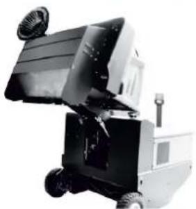
natural_image
Professional Karcher cleaning robot with visible brush and control panel (no text or symbols on the device itself)Deutsch 3
English 19
Français 35
Italiano 51
Nederlands 67
Español 83
Português 99
Dansk 115
Norsk 130
Svenska 145
Suomi 160
Ελληνικά 175
Türkçe 192
Русский 208
Magyar 225
Čeština 241
Slovenščina 257
Polski 273
Românește 289
Slovenčina 305
Hrvatski 321
Srpski 337
Български 353
Eesti 370
Latviešu 385
Lietuviškai 401
Українська 417
中文 434
العربية 462


1 Hydraulikpumpe
2 Schlüssel
3 M u t t e r
natural_image
Diagram of a medical or laboratory procedure showing a device with tubing and a circular component, no text or symbols present.natural_image
Close-up of a mechanical assembly with three numbered parts (1, 2, 3) and a textured floor panel, no visible text or symbols.1 Bremspedal
natural_image
Black and white photo of a small industrial machine with wheels and a fan (no visible text or symbols)natural_image
Close-up of a mechanical assembly with labeled parts (1 and 2), showing a red tool inserted into a blue component with wires and connectors (no readable text or symbols)natural_image
Electrical testing setup with a battery pack and connected wiring (no visible text or symbols)natural_image
Close-up of an internal combustion engine bay with hoses and components (no visible text or symbols)natural_image
Close-up of a mechanical engine component with numbered parts (1 and 2), no visible text or symbols beyond labels1 Ölablassschraube
2 Motorölfilter
natural_image
Close-up of a dark vehicle's side panel with a tire and attached metal component (no visible text or symbols)1 Schlüssel
2 Seitenverkleidung
natural_image
Interior view of a stainless steel industrial chamber with visible ductwork and structural beams (no text or symbols)1 Haltebügel
2 Flügelmutter
natural_image
Abstract geometric pattern with diagonal stripes and a blue upward arrow (no text or symbols)natural_image
Close-up of a mechanical assembly with labeled parts (1 and 2), showing a red tool inserted into a gray panel and wiring (no text or symbols visible)natural_image
Technical diagram of a mechanical housing component with labeled parts and an arrow indicating rotation (no text or symbols present)natural_image
Close-up of a metallic rack with slatted metal frame and two numbered measurement lines (no text or symbols)natural_image
Technical line drawing of a mechanical assembly with gears and springs (no text or symbols)natural_image
Interior view of a mechanical or industrial device with visible pipes, valves, and a mesh grille (no readable text or symbols)Chairman of the Board of Management

S. Reiser
Director Regulatory Affairs & Certification
71364 Winnenden (Germany)
Tel.: +49 7195 14-0
Fax: +49 7195 14-2212
Winnenden, 2020/01/01
General notes ..... EN 1
Environmental protection EN 1
Warranty ..... EN 1
Accessories and Spare Parts....EN 1
Symbols in the operating instructions ..... EN 1
Symbols on the machine EN 1
Proper use.....EN 2
Foreseeable misuse....EN 2
Suitable surfaces ..... EN 2
Safety instructions ..... EN 2
Safety instructions concerning the operation ..... EN 2
Safety information concerning the driving operation. EN 2
Safety regulations for LPG vehicles ..... EN 2
Appliances with combustion engine ....EN 3
Appliances with high emptying system ....EN 3
Devices with overhead guard....EN 3
Safety information concerning the transport of the appliance ..... EN 4
Safety information concern- ing maintenance and care EN 4
Function.....EN 4
Unloading tips ..... EN
Operating and Functional Ele-
ments.....EN 5
Illustration of sweeper .. EN 5
Operating field ..... EN 5
Pedals ..... EN 5
Indicator lamps and display EN 6
Before Startup ..... EN 6
Lock/ release parking brake EN 6
Moving sweeper without en-gaging self-propulsion . . EN 6
Start up ...... EN 6
General notes ..... EN 6
Install/replace gas bottle EN 6
Inspection and maintenance work....EN 6
Operation.....EN 7
Adjusting driver's seat .. EN 7
Open the gas supply . . . EN 7
Starting the machine . . . EN 7
Drive the machine ..... EN 7
Sweeping mode ..... EN 7
Emptying waste container EN 8
Turn off the appliance .. EN 8
Transport....EN 8
Storage/decommissioning .... EN 8
Care and maintenance ..... EN 8
General notes ..... EN 8
Cleaning.....EN 8
Maintenance intervals .. EN 8
Maintenance Works .... EN 9
Troubleshooting..... EN 14
Technical specifications.....EN 15
EU Declaration of Conformity. EN 16

Please read and comply with these original instructions prior
to the initial operation of your appliance and store them for later use or subsequent owners.
General notes
Your sales outlet should be informed about any transit damage noted when unpacking the product.
- Warning and information plates on the machine provide important directions for safe operation.
– In addition to the information contained in the operating instructions, all statutory safety and accident prevention regulations must be observed.
Environmental protection
| The packaging material can be recycled. Please do not throw the packaging material into household waste; please send it for recycling. | |
| Old appliances contain valuable materials that can be recycled. Please arrange for the proper recycling of old appliances. Please dispose your old appliances using appropriate collection systems. | |
| Do not allow fluids such as motor oil, hydraulic oil, brake fluid, diesel or coolant to enter the soil. Please protect the environment and dispose of fluids in an environmentally responsible way. | |
Notes about the ingredients (REACH)
You will find current information about the ingredients at:
www.kaercher.com/REACH
Warranty
The warranty terms published by the relevant sales company are applicable in each country. We will repair potential failures of your appliance within the warranty period free of charge, provided that such failure is caused by faulty material or defects in manufacturing. In the event of a warranty claim please contact your dealer or the nearest authorized Customer Service center.
Please submit the proof of purchase.
Accessories and Spare Parts
△DANGER
To avoid risks, all repairs and replacement of spare parts may only be carried out by authorized customer service personnel.
- Only use accessories and spare parts which have been approved by the manufacturer. The exclusive use of original accessories and original spare parts ensures that the appliance can be operated safely and trouble free.
- For additional information about spare parts, please go to the Service section at www.kaercher.com.
Symbols in the operating instructions
△DANGER
Warns about immediate danger which can lead to severe injuries or death.
⚠ WARNING
Warns about possible danger which could lead to severe injuries or death.
△CAUTION
Points out a possibly dangerous situation which can lead to light injuries or property damage.
ATTENTION
Pointer to a possibly dangerous situation, which can lead to property damage.
Symbols on the machine
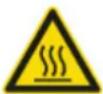 | Risk of burns on account of hot surfaces! Allow the ex-haust to cool down sufficiently before starting work on the machine. |
 | Always use appropriate gloves while working on the device. |
 | Risk of getting squeezed on account of getting jammed between vehicle parts. |
 | Risk of injury on account of moving parts. Do not reach in. |
 | Risk of fire. Do not vacuum up any burning or glowing objects. |
 | Chain pick-up / crane point |
 | Intake points for the jack |
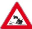 | Maximum decline of ground when driving with the waste container raised. |
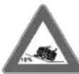 | The gradient in the direction of travel should not exceed 18%. |
 | Observe the installation position of the gas cylinder. The connection / ring opening must point downwards. |
Proper use
Use this sweeper only as directed in these operating instructions.
- This sweeper has been designed to sweep dirt and debris from outdoor surfaces.
– The machine is not suitable for being driven on public roads.
– Any use extending beyond this is not considered as proper use. The manufacturer is not liable for any losses resulting from this; the user alone bears the risk for this.
- (Gas motor)
The device is permitted for operation in confined spaces with sufficient ventilation.
– Gas bottles and appliance may only be stored on ground level.
– The machine may not be modified.
- The machine is only suitable for use on the types of surfaces specified in the operating instructions.
– The machine may only be operated on the surfaces approved by the company or its authorised representatives.
- The following applies in general: Keep highly-flammable substances away from the appliance (danger of explosion/fire).
Foreseeable misuse
- Never vacuum up explosive liquids, combustible gases or undiluted acids and solvents. This includes petrol, paint thinner or heating oil which can generate explosive fumes or mixtures upon contact with the suction air. Acetone, undiluted acids and solvents must also be avoided as they can harm the materials on the machine.
- Never sweep/vacuum up reactive metal dusts (e.g. aluminium, magnesium, zinc), as they form explosive gases when they come in contact with highly alkaline or acidic detergents.
– The appliance is not suitable for sweeping off hazardous substances.
- Do not sweep/vacuum up any burning or glowing objects.
- The machine may not be used or stored in hazardous areas. It is not allowed to use the appliance in hazardous locations.
- It is strictly prohibited to take co-passengers.
- Pushing/pulling or transporting objects by means of this appliance is prohibited.
Suitable surfaces
- Asphalt
- Industrial floor
- Screed
- Concrete
- Paving stones
Safety instructions
Safety instructions concerning the operation
→ (Applicable for Finland only) The device may not be used at low ambient temperatures (below 0°C) if it is equipped with a PVC hose line. Contact Kärcher if should have questions regarding your device.
→ The machine with working equipment must be checked to ensure that it is in proper working order and is operating safely prior to use. Otherwise, the appliance must not be used.
→ If the appliance is used in hazardous areas (e.g. filling stations) the corresponding safety provisions must be observed. It is not allowed to use the appliance in hazardous locations.
△DANGER
Risk of injury!
→ Do not use the appliance without an overhead guard in areas where the operator might get hit by falling objects.
→ The operator must use the appliance properly. The person must consider the local conditions and must pay attention to third parties, in particular children, when working with the appliance.
→ It is important to follow all safety instructions, rules and regulations applicable for driving motor vehicles.
→ Prior to starting work, the operator must ensure that all protective devices are properly installed and function correctly.
→ The operator of the appliance is liable for accidents with other individuals or their property.
→ Ensure that the operator wears tight-fitting clothes. Wear sturdy shoes and avoid wearing loose-fitting clothes.
→ Check the immediate vicinity prior to starting (e.g. children). Ensure sufficient visibility!
→ Never leave the machine unattended so long as the engine is running. The operator may leave the appliance only when the engine has come to a standstill, the appliance has been protected against accidental movement, and the key has been removed.
→ Please remove the key, when not in use, to avoid unauthorised use of the appliance.
The appliance may only be used by persons who have been instructed in handling the appliance or have proven qualification and expertise in operating the appliance or have been explicitly assigned the task of handling the appliance.
→ This appliance is not intended for use by persons (including children) with limited physical, sensoric or mental capacities or lack of experience and/or skills, unless such persons are accompanied and supervised by a person in charge of their safety or if they received precise instructions on the use of this appliance.
→ Children should be supervised to prevent them from playing with the appliance.
CAUTION
Risk of damage! Do not sweep up straps, strings or wires as these may wrap around the brush roller.
Safety information concerning the driving operation
△DANGER
Risk of injury! Verify the stability of the ground prior to driving on it.
△DANGER
Risk of accident, risk of injury!
→ The travel speed must be adapted to the existing conditions.
Danger of tipping if gradient is too high.
→ The gradient in the direction of travel should not exceed 18%.
Danger of tipping on unstable ground.
→ Only use the machine on sound surfaces.
Danger of tipping with excessive sideways tilt.
→ The gradient perpendicular to the direction of travel should not exceed 10%.
Safety regulations for LPG vehicles
Hauptverband der gewerblichen Berufsgenossenschaften e.V. (HVBG / Germany). Liquefied gases (propellants) are butane and propane or a mixture of butane/propane. They are available in special cylinders. The operating pressure of these gases depends on the outside temperature.
△DANGER
Risk of explosion!
Do not handle liquified gas like petrol. Petrol evaporates slowly, liquified gas immediately turns into gas. The risk of gas spreading in the room and getting ignited is thus higher with liquid gas than with petrol.
CAUTION
Only use LPG cylinders filled with propellant gas in accordance with DIN 51622 quality.
The use of household gas and camping gas is strictly prohibited.
Liquid gas mixtures can be different for different gas motors. The approved liquid gas mixtures can be found in the technical data.
Liabilities of the factory management and the employee
- All persons handling liquid gases are liable to acquaint themselves with the special properties of the liquefied gases for hazard-free handling of operations. The current documentation is always to be kept with the sweeper.
Maintenance by expert
- Propellant-operated units are to be checked at regular intervals, at least once a year, by an expert against leaks (according to BGG 936) and ensure that the unit is functioning properly.
- The inspection must be certified and documented. The inspection guidelines are § 33 and § 37 UVV (occupation accident prevention regulations) "Use of liquid gas" (BGV D34).
– General applicable regulations are the guidelines for inspecting vehicles whose engines are driven by liquefied gases of the Federal Transportation Minister.
Commissioning/Operations
- Gas must always be drawn only from one cylinder. Drawing gas from multiple cylinders simultaneously can cause liquid gas from one cylinder flowing into the other. This causes the over-filled cylinder to be subjected to an unpermitted excess pressure when the cylinder valve is closed later (refer B.1 of these guidelines).
- Note the installation position of the gas connection during installation of the full bottle, further information in chapter "Installing the gas bottle".
Perform the replacement of the gas cylinder carefully. During assembly and disassembly, the gas outlet nozzle of the cylinder valve must be sealed by means of a cap nut that is tightened using a wrench.
- Discontinue the use of leaky gas cylinders. Such cylinders are to be emptied by slowly letting out the gas in open spaces by conforming to all safety regulations and are to be indicated as leaky. Also inform the issuing company or its representative (the filling-station attendant) in writing about the damage to the cylinder while delivering or receiving the cylinders.
– Before connecting the gas cylinder, check that its connection neck is in a proper state. - After connecting the cylinder, regularly check that it is not leaky by using a foaming agent.
- Open the valves slowly. Do not use ham- mers to open and close the cylinders.
- Fight liquid-gas fires only from a safe distance and with protection.
- use only dry powder carbon dioxide extinguishers or carbon dioxide gas extinguishers.
- use abundant water to cool the gas tank.
- The entire LPG unit must be continuously checked to ensure that there are no leaks and the unit is functioning properly. Using the vehicle with a leaky gas unit is strictly prohibited.
- First close the cylinder valve before loosening the pipe or tube connection. Unscrew and loosen the connection nut of the gas cylinder slowly because otherwise the gas under pressure in the tube will flow out instantly.
- If the gas is refilled from a larger tank, then ask the sales agent of the LPG about the important regulations to be followed.
⚠Danger
Risk of injury!
- LPG in a liquid state can cause frost bites on bare skin.
- After disconnecting the cylinder, tighten the closing nut firmly on the connecting threading of the cylinder.
- Use soap water or some such foaming agent to check whether the cylinder is leaking. The use of open flames to illuminate the LPG unit is strictly prohibited.
- Follow the manufacturer's installation specifications while changing individual parts of the LPG unit. Close all cylinder and locking valves while doing so.
- Regularly check the status of the electrical unit of the LPG vehicles. Sparks can cause explosions if the gas-carrying parts of the unit are leaky.
- If a LPG-driven vehicle has been idling for a long time, then first ventilate the setting room before commissioning the vehicle or its electrical unit.
- Immediately inform the trade association and the concerned trade supervisory authority about accidents with gas cylinders or LPG units. Store the damaged parts carefully until all investigations have been completed.
In the installation and storage rooms as well as the workshops
- Propellants or LPG cylinders must always be stored according to the regulations of TRF 1996 (Technical Regulations for Liquid Gases, refer DA to BGV D34, Appendix 4).
- Always store the gas cylinders in a vertical position. Use of open flames and smoking at the installation site of the cylinders and during repairs is strictly prohibited. Protect the stored cylinders against unauthorised access. Close all empty cylinders properly.
- Close the cylinder and main locking valves immediately when you switch off the vehicle.
– Follow the regulations for garages and the construction guidelines of the respective State about the location and structure of the parking areas for LPG-driven vehicles.
– Gas cylinders are to be stored in separate rooms away from the parking areas (refer DA to BGV D34, Appendix 2). - The electrical hand-held lamps used in the rooms are to be equipped with closed, sealed case and a strong protection cover.
- Close all cylinder and main valves before working in repair workshops and protect the gas cylinders against effect of external heat.
– A responsible person must check that all valves, especially the cylinder valves, are closed during operational breaks and before closing the factory.
Do not carry out any jobs involving fire - such as cutting and welding jobs - in the vicinity of the gas cylinders. Do not store gas cylinders, not even empty ones, in the workshops.
- The parking and storage rooms and the repair workshops must be ventilated properly. Please note that liquefied gases are heavier than atmospheric air. They get collected on the floor, in recesses and other holes in the floors and form a gas-air mixture that can lead to explosions.
Appliances with combustion engine
→ Do not use the device at elevations of over 1200 m.
△DANGER
Risk of poisoning!
→ (Gas motor)
The device is permitted for operation in confined spaces with sufficient ventilation.
→ Exhaust gases are poisonous and hazardous to health, do not inhale them.
△DANGER
Risk of injury!
→ The exhaust gas opening of the combustion engine must not be closed.
→ The motor requires approx. 3 seconds to come to a standstill once it has been switched off. During this time, stay well clear of the drive area.
DANGER
Risk of burns!
→ Do not touch hot combustion engine.
→ Allow the vehicle to cool down before removing the panels.
→ Do not bend over the exhaust or touch it.
Appliances with high emptying system
△DANGER
Risk of injury!
→ When working on the high emptying system, completely lift and secure the waste container.
→ Perform the safeguarding only from outside the hazard zone.
Devices with overhead guard
NOTICE
The overhead guard (optional) protects the driver against larger falling objects. However, it does not provide rollover protection!
→ Check the overhead guard for damage daily.
→ If the overhead guard, as well as individual elements, should be damaged, replace the entire overhead guard.
→ Any modification of the overhead guard and installation of elements, components and assemblies other than those approved by Kärcher is not permitted and may limit the function of the overhead guard.
Safety information concerning the transport of the appliance
→ Observe the net weight (transport weight) of the device during transport on trailers or vehicles.
→ Disconnect the battery and securely fasten the device for transport.
Safety information concerning maintenance and care
→ First switch off the appliance and remove the key before performing any cleaning or maintenance tasks on the appliance, replacing parts or switching over to another function.
→ Always disconnect the battery when working on the electrics.
To do this, first disconnect the negative terminal and then the positive terminal. Reconnection is performed in reverse sequence. Connect the positive terminal first, then connect the negative terminal.
→ Do not clean the appliance with a water hose or high-pressure water jet (danger of short circuits or other damage).
→ Maintenance work may only be carried out by approved customer service outlets or experts in this field who are familiar with the respective safety regulations.
→ Please observe the local safety regulations regarding portable commercially used appliances.
→ Always use appropriate gloves while working on the device.
Function
The sweeper operates using the sweep-shovel principle.
- The rotating roller brush moves the dirt directly into the waste container.
- The side brush cleans the corners and edges of the surface and moves dirt and debris into the path of the roller brush.
- The fine dust is sucked in via the dust filter through the suction blower.
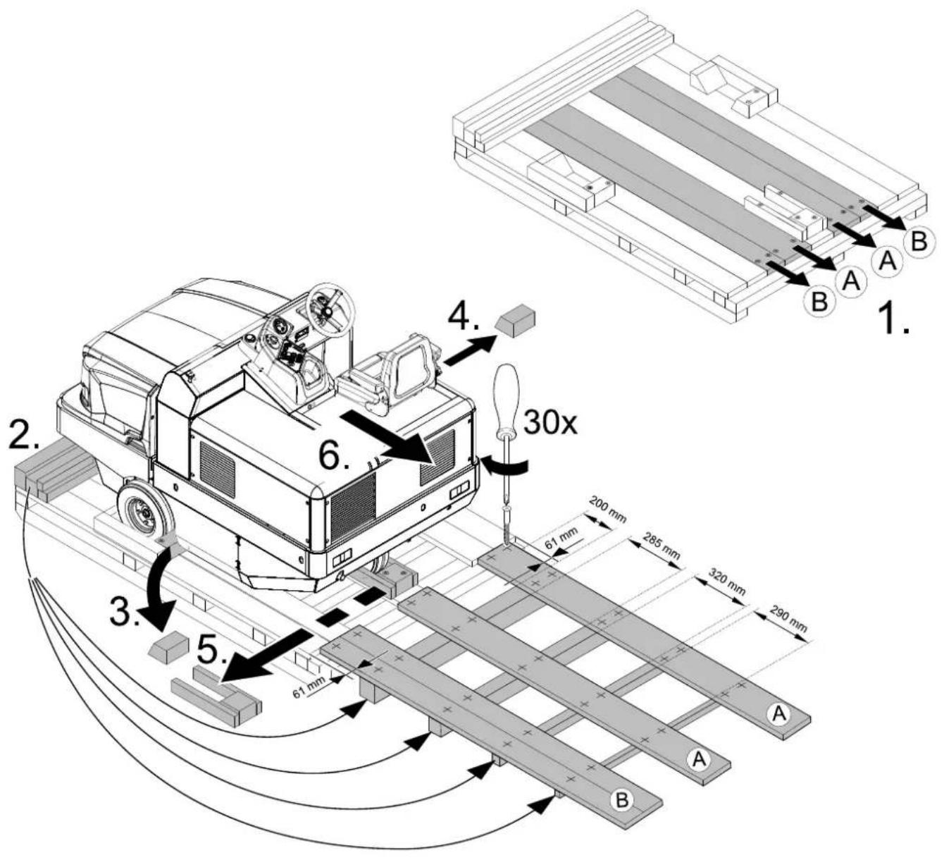
Unloading tips
△DANGER
Risk of personal injury or damage!
→ Observe the weight of the appliance when you load it!
→ Do not use a fork lift, the appliance could get damaged.
Net weight (transport weight) 851 kg*
* If upgrade kits are installed, the weight is respectively higher.
→ Use a suitable ramp or a crane to load the appliance!
→ Observe when using a ramp: Ground clearance 70 mm.
→ If the machine is delivered on a pallet, you must create an unloading ramp using the boards provided.
You will find the instructions for this procedure on page 2 (inside of cover).
Important instruction: every board must be attached with at least 2 screws.
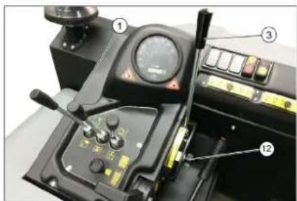
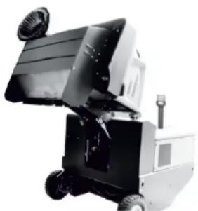
Operating and Functional Elements
A
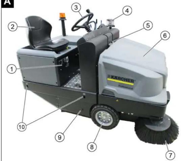
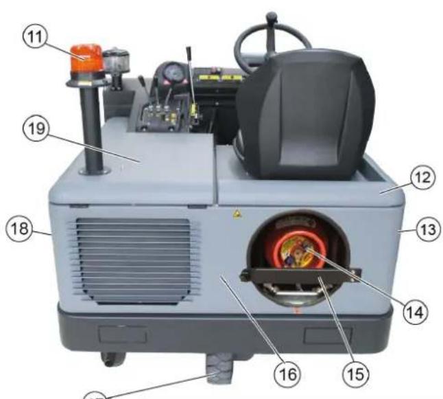


Illustration of sweeper Operating field
Illustration A
1 Nameplate
2 Seat (with seat contact switch)
3 Steering wheel
4 Centrifugal separator
5 Lock of appliance hood
6 Cover
7 Side brush, right
8 Front wheel
9 Roller brush access
10 Lashing point
11 Beacon lamp
12 Appliance cover right side
13 Cover, right
14 Gas cylinder
15 Safety rod
16 Tail panel
17 Rear wheel
18 Cover, left
19 Bonnet left side (engine bonnet)
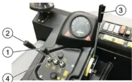
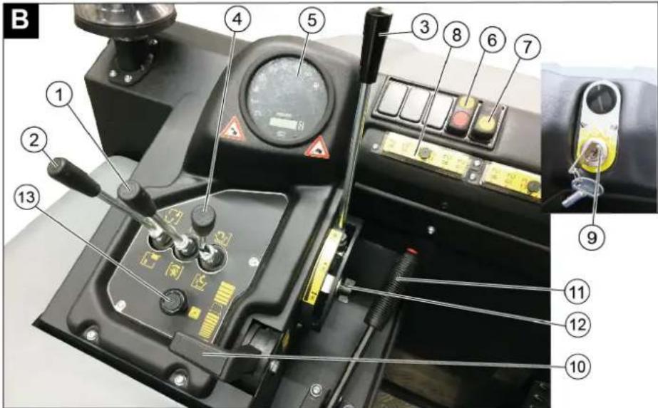
Illustration B
1 Roller brush and side brush control lever
Lever forwards: Switches the roller brush on and lowers and switches the side brushes on.
Lever backwards: Switches the roller brush on
2 Control lever waste container
Raise/lower waste container
3 Roller brush control lever
Raises and lowers the roller brush
4 Control lever container flap Open/close container lid
5 Indicator lamps and display
6 Switch blower and filter cleaning
Position centred: Filter cleaning and blower off
Front position: Blower on
Rear position: Filter cleaning on and blower off
7 Horn switch
8 F u s e s
9 Ignition lock
Position 0: Switch off engine
Position 1: Ignition on
Position 2: Start the engine
10 Gas lever
Motor speed adjustment
11 Parking brake
12 Roller brush wear adjustment / sweeping area setting
13 Choke
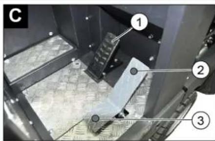
Pedals
Illustration ©
1 Brake pedal
2 Accelerator pedal, "forwards"
3 Accelerator pedal, "reverse"
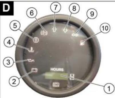
Indicator lamps and display
Illustration D
1 Operating hour counter
2 Charge warning lamp
3 Oil pressure warning lamp
4 Cooling water temperature warning lamp
5 Motor suction air
6 Warning light parking brake operated
7 Forward travel direction
8 Direction of travel reverse
9 Indicator light parking light/low beam (option)
10 Warning lamp fuel reserve
- blinks for reserve
- illuminates when gas bottle is empty
Before Startup
Lock/ release parking brake
→ Loosen parking brake; press brake pedal at the same time.
→ Activate the parking brake; press brake pedal at the same time.
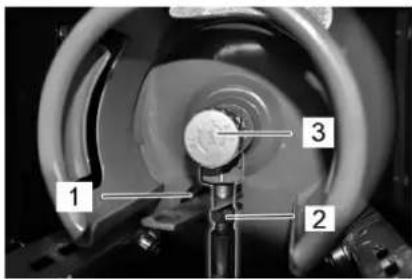
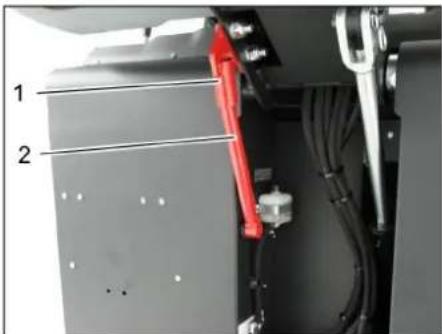
Moving sweeper without engaging self-propulsion
Note
This procedure is necessary if the device needs to be pushed off the palette or towed away, or must be moved onto a transport vehicle without its own drive.
ATTENTION
Do not move the machine for long distances without engaging self-propulsion; a speed of 10 km/h should not be exceeded.
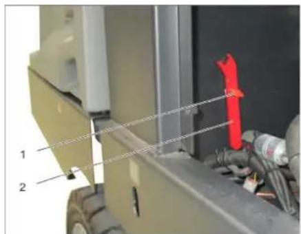
1 Screw
2 Key
→ Unscrew the screw.
→ Remove the spanner.

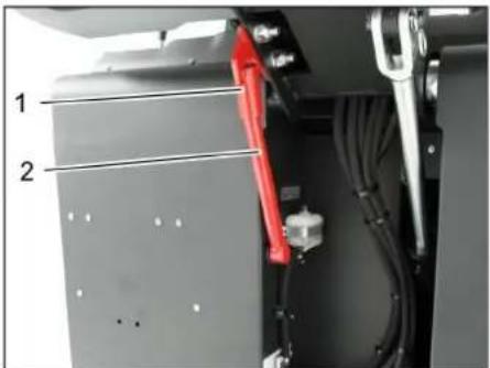
1 Hydraulic pump
2 Key
3 Nut
→ Loosen the nut using the spanner (open freewheel) until the device can be pushed.
→ IMPORTANT: Once pushed, reclose the nut (close freewheel = drive position).
Start up
General notes
→ Read the operating instructions of the engine manufacturer before start-up and follow the safety instructions carefully.
→ Park the sweeper on an even surface.
→ Remove ignition key.
→ Lock parking brake.
Install/replace gas bottle
△DANGER
Risk of injury!
→ Follow safety regulations for LPG vehicles.
→ Formation of crusts and yellow-frothing deposits on the gas cylinder indicate leakiness.
→ Cylinders must be changed only by instructed persons.
→ Cylinders containing propellant gases must not be changed in garages and underground areas.
→ Do not smoke and use uncovered light while changing the cylinder.
→ While changing cylinders, first close the locking valve of the LPG cylinder firmly and immediately put the protective cap on the empty cylinder.
⚠ WARNING
Only use replacement cylinders with 11 kg contents of tested models.
CAUTION
The use of household gas and camping gas is strictly prohibited.
LPG mixtures of propane and butane are permitted. The propane content must be at least 90%.
Installing the gas bottle
ATTENTION
Observe the installation position of the gas cylinder. The connection / ring opening must point downwards.
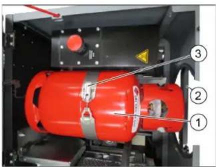
1 Gas cylinder
2 Safety rod
3 Bracket closure
→ Release the screws on the safety rod and pivot the pole away.
→ Replace the gas cylinder.
→ Unscrew the protective cap from the connecting valve of the gas cylinder.
→ Close the bracket closure.
Connecting gas cylinder
ATTENTION
After connecting the cylinder, regularly check that it is not leaky by using a foaming agent.
1 Protective cover
2 Gas hose with union joint
3 Gas withdrawal valve
→ Screw the gas hose to the connecting valve of the gas cylinder (30-mm spanner).
→ Close the safety bar, and secure it with a bolt.
Replacing the empty gas bottle
If the warning indicator for reserve fuel shows an empty gas bottle continuously during operation, proceed as follows:
→ Close gas drawing valve by turning it in clock-wise direction.
→ Stop the machine and continue to run it at idle speed until the motor shuts off.
Note: This will ensure that all gas lines are empty and that there can be no icing which would hinder starting the motor.
→ Unscrew the gas hose (30-mm spanner).
→ Screw the protective cap onto the connecting valve of the empty gas cylinder.
→ Open the cliplock.
NOTICE
Connection has a left threading.
⚠ Warning
Open the gas drawing valve (3) only after starting the appliance (refer chapter Starting the appliance).
Inspection and maintenance work
Daily before starting operations
→ Check engine oil level.
→ Check the filling level in the coolant expansion tank.
→ Check the sweeping roller and the side brush for wear and wrapped belts.
→ Check the wheels for tied up belts.
→ Check the centrifugal separator and the air filter, clean if required.
→ Check function of all operator control elements.
→ Check appliance for damages.
→ Clean the dust filter with the filter cleaning button.
Note: For description, see section on Care and maintenance.
Operation
Adjusting driver's seat
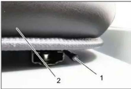
1 Lever for seat adjustment
2 Driver seat
→ Pull seat adjustment lever outwards.
→ Slide seat, release lever and lock in place.
→ Check that the seat is properly locked in position by attempting to move it backwards and forwards.
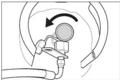
Open the gas supply
natural_image
Diagram of a medical or laboratory procedure showing a device with tubing and a rotating arrow (no text or symbols)→ Open the gas drawing valve by turning it in anti-clockwise direction.
Starting the machine
Note: The machine is equipped with a seat contact switch If the driver's seat is vacated, the machine is switched off.
→ Sit on the driver's seat.
→ Lock parking brake (11).
→ Push motor speed adjustment (10) 1/3 to the front.
Start the engine
→ Press the brake pedal in order to start the engine.
→ During cold exterior temperatures: Pull the choke (13).
→ Turn the ignition switch to the right and start the device.
→ If the machine starts, release the ignition key.
→ If the motor runs smoothly, push in the choke.
Note: Never operate the starter motor for longer than 10 seconds. Wait at least 10 seconds before operating the starter motor again.
Drive the machine
1 Brake pedal
2 Accelerator pedal, "forwards"
3 Accelerator pedal, "reverse"
→ Push the motor speed adjustment all the way to the front (operating speed).
→ Press brake pedal and keep it depressed.
→ Release parking brake.
Drive forward
→ Press slowly the accelerator pedal "forward".
Reverse drive
△DANGER
Risk of injury!
→ When reversing, there must not be any risk for third parties, have somebody marshal the driver if necessary.
→ Press slowly the accelerator pedal "reverse".
Driving method
→ The accelerator pedal can be used to vary the driving speed infinitely.
→ Avoid sudden operation of the pedal as this may damage the hydraulic system.
→ In the event of power loss on inclined surfaces, slightly reduce the pressure on the accelerator pedal.
Brakes
→ Release the accelerator pedal, the machine brakes automatically and stops.
Note: The braking effect can be supported by pressing the brake pedal.
Driving over obstacles
Driving over fixed obstacles which are 70 mm high or less:
→ Drive forwards slowly and carefully. Driving over fixed obstacles which are more than 70 mm high:
→ Only drive over these obstacles using a suitable ramp.
Sweeping mode
ATTENTION
Do not sweep up packing strips, wire or similar objects as this may damage the sweeping mechanism.
Note: To achieve an optimum cleaning result, the driving speed should be adjusted to take specific situations into account.
Note: During operation, the dust filter should be shaken off and cleaned at regular intervals.
Note: When frequently working in areas with fine dust, the filter must be cleaned more often.
Control lever
1 Roller brush and side brush control lever
2 Control lever waste container
3 Roller brush control lever
4 Control lever container flap
Roller brush and side brush control lever
→ Control lever (1) forwards: Switches the roller brush on and lowers and switches the side brushes on.
→ Control lever (1) backwards: Switches the roller brush on.
Control lever waste container
→ Control lever waste container (2) to the front: Waste container is lowered.
→ Control lever waste container (2) to the back: Waste container is raised.
Control lever roller brush
→ Roller brush control lever (3) forwards: Raises the roller brush.
→ Roller brush control lever (3) backwards: Lowers the roller brush.
Control lever container flap
→ Control lever container flap (4) to the front: The container flap of the waste container opens.
→ Control lever container flap (4) to the back: The container flap of the waste container closes.
Sweeping dry floors
→ Switch on the blower.
→ With surface cleaning:
Roller brush and side brush control lever (1) backwards: Switches the roller brush on.
Roller brush control lever (3) backwards: Lowers the roller brush.
→ Control lever container flap (4) to the front: Container flap opens.
→ With cleaning of side edges:
Roller brush and side brush control lever (1) forwards: Switches the roller brush on, switches the side brushes on and lowers them.
Roller brush control lever (3) backwards: Lowers the roller brush.
Sweeping damp or wet floors
→ Switch off the blower.
→ With surface cleaning:
Roller brush and side brush control lever (1) backwards: Switches the roller brush on.
Roller brush control lever (3) backwards: Lowers the roller brush.
→ Control lever container flap (4) to the front: Container flap opens.
→ With cleaning of side edges:
Roller brush and side brush control lever (1) forwards: Switches the roller brush on, switches the side brushes on and lowers them.
Roller brush control lever (3) backwards: Lowers the roller brush.
Emptying waste container
△DANGER
Risk of injury!
→ During the emptying process, persons and animals must not stay within the swivelling range of the waste container.
Danger of tipping!
→ Place the device on an even surface during the emptying process.
△WARNING
Risk of crushing!
→ Never reach into the rod assembly for the drainage mechanism. Do not stay under the raised container.
ATTENTION
Risk of personal injury or damage!
→ Material of the rotating roller brush may be catapulted off during the emptying process. Keep an appropriate distance.

natural_image
Black and white photo of a wheeled industrial machine with wheels and ventilation ducts (no visible text or symbols)→ Raise the roller brush and side brushes using the control levers: Control lever 1 to middle position and control lever 3 forwards.
→ Close the container flap, in order to do so, move the control lever (4) to the back:
→ Raise the container flap, in order to do so, move the waste container control lever (2) to the back:
→ Slowly drive towards the collection container.
→ Lock parking brake.
→ Open the container flap, in order to do so, push the container flap operating lever (4) to the front and empty the waste container.
→ Close the container flap, in order to do so, push the container flap operating lever (4) to the back until it is tipped inwards in the end position.
→ Release parking brake.
→ Drive away the collection container slowly.
→ Lower the waste container into the end position, in order to do so, move the waste container control lever (2) to the front
Turn off the appliance
→ Raise the roller brush and side brushes using the control levers: Control lever 1 to middle position and control lever 3 forwards.
→ Close the container flap, in order to do so, move the control lever (4) to the back:
→ Pull the motor speed adjustment all the way to the back.
→ Press brake pedal and keep it depressed.
→ Lock parking brake.
→ Turn ignition key to "0" and remove it.
Transport
△DANGER
Transport damage!
→ Observe the net weight (transport weight) of the device during transport on trailers or vehicles.
→ When transporting in vehicles, secure the appliance according to the guidelines from slipping and tipping over.
→ Turn ignition key to "0" and remove it.
→ Close gas drawing valve by turning it in clock-wise direction.
→ Lock parking brake.
→ Secure the appliance at the lashing points (4x) using tension belts, ropes or chains.
→ Secure the wheels of the machine with wheel chocks.
Storage/decommissioning
△DANGER
Risk of injury and damage! Note the weight of the appliance in case of storage.
→ Park the sweeper on a level surface in a dry, frost protected area. Protect it against dust by means of covering material.
→ Raise the roller brush and the side-brushes to prevent the bristles from being damaged.
→ Close the container flap.
→ Turn ignition key to "0" and remove it.
→ Close gas drawing valve by turning it in clock-wise direction.
Unscrew the gas hose with union nut (use 30 mm spanner).
Lock the gas bottle with the safety cap and store upright in a suitable storage area (also see Chapter "Safety instructions).
→ Lock parking brake.
→ Lock the sweeper to ensure that it does not roll off.
Additionally observe the following points if the sweeper is not used over a longer period of time:
→ Change engine oil.
→ Drain off the cooling water if frost is expected and check whether there is adequate anti-frosting agent.
→ Clean the inside and outside of the sweeper.
→ Disconnect battery.
→ Charge battery and recharge it approx. every 2 months.
Care and maintenance
General notes
ATTENTION
Risk of damage!
→ Do not rinse out the dust filter.
→ Maintenance work may only be carried out by approved customer service outlets or experts in this field who are familiar with the respective safety regulations.
→ Always disconnect the battery when working on the electrics.
→ Mobile appliances used for commercial purposes are subject to safety inspections according to VDE 0701.
→ Park the sweeper on an even surface.
→ Turn ignition key to "0" and remove it.
→ Lock parking brake.
→ Close the gas inlet.
Cleaning
CAUTION
Risk of damage!
Do not clean the appliance with a water hose or high-pressure water jet (danger of short circuits or other damage).
Cleaning the inside of the machine
△DANGER
Risk of injury!
→ Wear dust mask and protective goggles.
→ Clean machine with a cloth.
→ Blow through machine with compressed air.
External cleaning of the appliance
→ Clean the machine with a damp cloth which has been soaked in mild detergent.
Note: Do not use aggressive cleaning agents.
Maintenance intervals
Note: The elapsed-time counter shows the timing of the maintenance intervals.
Maintenance by the customer
Note: Where maintenance is carried out by the customer, all service and maintenance work must be undertaken by a qualified specialist. If required, a specialised Kärcher dealer may be contacted at any time.
Daily maintenance:
→ Check engine oil level.
→ Check the filling level in the coolant expansion tank.
→ Check the sweeping roller and the side brush for wear and wrapped belts.
→ Check the centrifugal separator and the air filter, clean if required.
→ Check function of all operator control elements.
→ Check appliance for damages.
Weekly maintenance:
→ Check gas lines, connections and joints
→ Clean the water cooler.
→ Clean the hydraulic oil cooler.
→ Check hydraulic unit.
→ Check the hydraulic oil level.
→ Check brake fluid status.
→ Check the pad for wear, replace if required.
→ Check the container lid and lubricate it.
Maintenance following wear:
→ Replace sealing strips.
→ Readjust the side seals or replace them.
→ Replace roller brush.
→ Replace side brush.
Note: For description, see section on Maintenance work.
Maintenance by Customer Service
Note: In order to safeguard warranty claims, all service and maintenance work during the warranty period must be carried out by the authorised Kärcher Customer Service in accordance with the maintenance booklet.
Maintenance to be carried out after 50 operating hours:
→ Have the first maintenance performed by the customer service in accordance with the inspection check list.
Maintenance after 250/500/1000/1500/2000 operating hours:
→ Have the maintenance performed by the customer service in accordance with the inspection check list.
Maintenance Works
Preparation:
→ Park the sweeper on an even surface.
→ Turn ignition key to "0" and remove it.
→ Lock parking brake.
→ Close the gas inlet.
General notes on safety
△DANGER
Risk of injury!
→ Always apply the safety rod when the waste container is raised.
→ Perform the safeguarding only from outside the hazard zone.
natural_image
Close-up of a mechanical assembly with labeled parts (1 and 2), showing a red robotic arm and wiring (no readable text or symbols)1 Holder of safety rod
2 Safety rod
→ Fold the safety rod for the high emptying up and insert it into the holder (secured).

Do not allow fluids such as motor oil, hydraulic oil, brake fluid, diesel or coolant to enter the soil. Please protect the environment and dispose of fluids in an environmentally responsible way.
Safety notes regarding the batteries
Please observe the following warning notes when handling batteries:
| Observe the directions on the battery, in the instructions for use and in the vehicle operating instructions! | |
| Wear an eye shield! | |
| Keep away children from acid and batteries! | |
| Risk of explosion! | |
| Fire, sparks, open light, and smoking not allowed! | |
| Danger of causticization! | |
| First aid! | |
| Warning note! | |
| Disposal! | |
| Do not throw the battery in the dustbin! |
△DANGER
Risk of explosion!
→ Only use batteries with terminal cover. Restore terminal cover in the event of loss.
△DANGER
Risk of explosion!
Do not place tools or similar items on the battery. Risk of short-circuit and explosion.
△DANGER
Risk of injury!
→ Ensure that wounds never come into contact with lead. Always clean your hands after working on batteries.
△DANGER
Risk of fire and explosion!
→ Smoking and naked flames are strictly prohibited.
→ Rooms where batteries are charged must have good ventilation because highly explosive gas is emitted during charging.
△DANGER
Danger of causticization!
→ Rinse thoroughly with lots of clear water if acid gets into the eye or comes in contact with the skin.
→ Then consult a doctor immediately.
→ Wash off the acid If it comes in contact with the clothes.
Installing and connecting the battery
Normally, the machine is equipped with a maintenance-free battery.
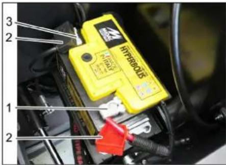
1 Positive terminal
2 Terminal cover
3 Negative terminal
→ Insert battery in battery mount.
→ Screw on mounts on battery base.
→ Connect pole terminal (red cable) to positive pole (+).
→ Connect pole terminal to negative pole (-).
→ Attach the pole covers.
→ Check that the battery poles and pole terminals are adequately protected with pole grease.
Check and correct the fluid level of the battery (only with low-maintenance battery with cell caps)
CAUTION
Risk of damage!
→ Regularly check the fluid level in acid-filled batteries.
→ Unscrew all cell caps.
→ Take a sample from each cell using the acid tester.
- The acid in a fully charged battery has a specific weight of 1.28 kg/l at a temperature of 20 °C.
- The acid in a partially discharged battery has a specific weight between 1.00 and 1.28kg / l .
- The specific weight of the acid must be uniform in all cells.
→ Put the acid sample back into the same cell.
→ Where fluid level is too low, top up cells to the mark provided with distilled water.
→ Charge battery.
→ Screw in cell caps.
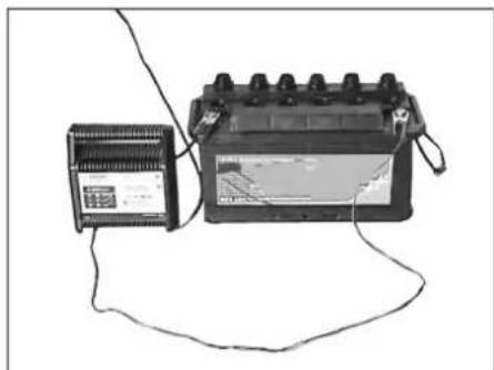
Charging battery
△DANGER
Risk of injury!
→ Comply with safety regulations on the handling of batteries. Observe the directions provided by the manufacturer of the charger.
△DANGER
Risk of damage!
→ Charge the battery only with an appropriate charger.
natural_image
Electrical testing setup with battery pack and connected wiring (no visible text or symbols)→ Unscrew all cell caps.
(only with low-maintenance battery)
→ Connect positive terminal cable from the charger to the positive pole connection on the battery.
→ Connect negative terminal cable from the charger to the negative pole connection on the battery.
→ Plug in mains connector and switch on charger.
→ Charge battery using lowest possible level of charging current.
→ When the battery is charged, first remove the charger from the mains and then disconnect it from the battery.
→ Screw in cell caps.
(only with low-maintenance battery)
Remove the battery
→ Disconnect pole terminal to negative pole (-).
→ Disconnect pole terminal to positive pole (+).
→ Loosen the mounts on battery base.
→ Remove the battery from the battery holder.
→ Dispose of the used battery according to the local provisions.
Checking the brake fluid level and topping up brake fluid
△DANGER
Risk of injury!
→ Always apply the safety rod when the waste container is raised.
→ Perform the safeguarding only from outside the hazard zone.
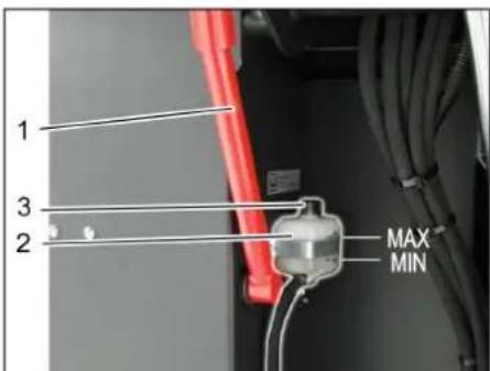
1 Holder of safety rod
2 Brake fluid container
3 Closing head
Move up the waste container and secure it by means of the safety rod, see Chapter "Emptying the waste container"
→ Check if the there is enough brake fluid in the brake fluid reservoir.
Note
The filling level has to be between Min. and Max.
→ If necessary, refill DOT brake fluid currently commercially available.
Check engine oil level and top up, if required
△DANGER
Risk of burns!
→ Allow engine to cool down.
→ Wait for at least 5 minutes after switching off the engine before checking the engine oil fill level.
natural_image
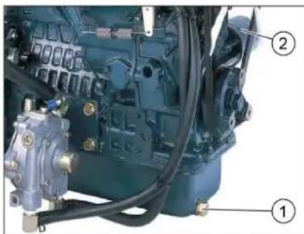
Close-up of an internal combustion engine bay with hoses and components (no visible text or symbols)1 Oil cap (engine)
2 Oil dipstick
→ Pull out oil dipstick.
→ Wipe off oil dipstick and insert.
→ Pull out oil dipstick.
→ Read the value of the oil level.
→ Insert the oil dip again.
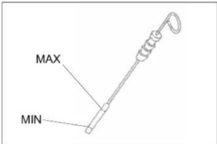
- The oil level must lie between "MIN" and "MAX" marking.
- Add motor oil if the oil level is below the "MIN" marking.
- Do not fill oil above the "MAX" marking.
→ Remove oil cap.
→ Fill in motor oil. For oil type refer to Chapter "Technical specifications".
→ Close oil cap.
→ Wait at least 5 minutes.
→ Check engine oil level.
Change the motor oil and the oil filter CAUTION
Risk of burns due to hot engine oil!
→ Allow engine to cool down.
→ Prepare a collection container for at least 6 litres of engine oil.
→ Allow engine to cool down.
natural_image
Close-up of a mechanical engine component with visible gears and hoses (no text or symbols)1 Oil drain screw
2 Engine oil filter
→ Unscrew oil drain plug.
→ Remove oil cap.
→ Drain off oil.
→ Unscrew the oil filter.
→ Clean the intake and sealing areas.
→ Coat the washer of the new oil filter with oil before fitting it.
→ Fit in the new oil filter and tighten it by hand.
→ Screw in the oil drain screw along with the new washer.
Tightening torque: 25 Nm
→ Fill in motor oil.
For oil type and filling quantity refer to Chapter "Technical specifications".
→ Close oil cap.
→ Let the motor run for approx. 10 seconds.
→ Check engine oil level.
Check hydraulic oil level and refill hydraulic oil
NOTICE
The waste container must not be raised.
→ Open the device hood and secure it using the hood support.
1 Hydraulic oil sight glass
2 Hydraulic tank
3 Screw cap, oil fill opening
4 Hood support
→ Check hydraulic oil level in the looking glass.
- The oil level must lie between "MIN" and "MAX" marking.
- Add hydraulic oil if the oil level is below the "MIN" marking.
→ Loosen the closing cap of the oil filling opening.
→ Clean the filling area.
→ Refill hydraulic oil.
For oil type refer to Chapter "Technical specifications".
→ Replace and tighten the closing cap of the oil filling opening.
Check hydraulic unit
NOTICE
Only Kärcher Customer Service is authorised to carry out maintenance tasks on the hydraulic unit.
→ Lock parking brake.
→ Start the motor.
→ Check all hydraulic hoses and connections and ensure that they are leak-proof.
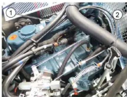
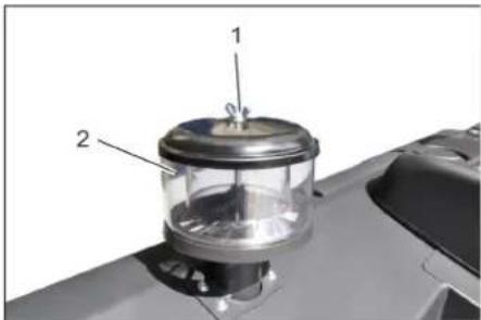
Check coolant level
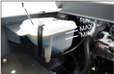
1 Coolant expansion tank
→ Check filling level while the motor is cold.
→ Check the filling level in the coolant expansion tank.
The correct coolant level has to be between MIN and MAX.
Checking and cleaning water/hydraulic oil cooler
△DANGER
Risk of burning and scalding!
→ Allow the water cooler to cool down for at least 20 minutes.
The coolant level of the water cooler is checked at the coolant expansion tank. See chapter "Checking the cooling water level".
→ Clean cooler lamella.
Remove soiling by means of a soft brush, compressed air or low water pressure.
→ Check cooler hoses and connections and ensure that they are leak-proof.
→ Clean the fan.
Checking roller brush
→ Start the motor.
→ Raise the waste container up to the end-position.
→ Switch off engine.
→ Lock parking brake.
→ Use the safety bar for emptying from a height.
→ Remove belts or cords from roller brush.
→ Remove the safety bar.
→ Start the motor.
→ Lower the waste container up to the end-position.
→ Switch off engine.
Replacing roller brush
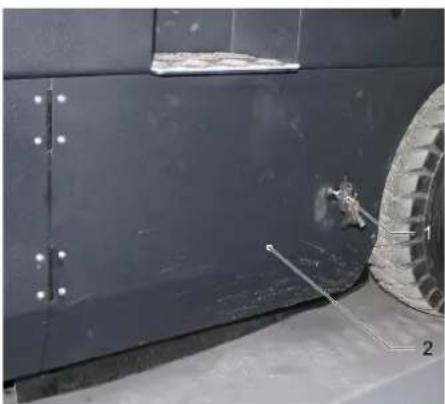
natural_image
Close-up of a dark metal vehicle's side panel with two circular tires and a small object on the wheel (no visible text or symbols)1 Key
2 Side panels
→ Drive the waste container up and support it with the safety rod.
→ Open the side covers using a key.

natural_image
Interior view of a laboratory or industrial facility with three numbered components connected by wires, no visible text or symbols.1 Holding bow
2 Wing nut
3 Side seal
→ Unscrew the wing nuts.
→ Remove the retaining clamp.
→ Flip the side seal out.
→ Uncscrew the retaining screw of the roller brush intake, and swing the intake to the outside.
→ Pull out roller brush.
natural_image
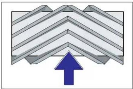
Diagram of a layered structure with an upward-pointing arrow, no text or symbols presentInstallation position of roller brush in direction of travel (top view)
Note: When installing the new roller brush, ensure correct positioning of the bristle assembly.
→ Install new roller brush. The nuts of the roller brush must be inserted on the notches of the opposite crank.
Note: Once the new roller brush has been installed, the sweeping track must readjusted.
Check and adjust roller brush sweeping track
Note: The sweeping track is factory-set to 80 mm; it is steplessly adjustable if the brush roller wears down.
→ Check tyre pressure.
→ Switch off suction blower.
→ Drive sweeper on to a smooth, even surface covered with a visible layer of dust or chalk.
→ Roller brush and side brush control lever (1) backwards: Switches the roller brush on.
Roller brush control lever (3) backwards: Lowers the roller brush.
→ Allow the roller brush to run for approx. 10 seconds.
→ Roller brush and side brush control lever (1) to middle position.
Roller brush control lever (3) forwards: Raises the roller brush.
→ Drive machine backwards.
→ Check sweeping mirror.
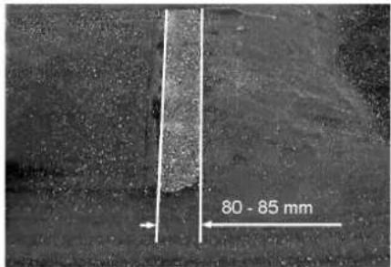
The sweeping track should have an even rectangular shape which is 80-85 mm wide.
→ Undo and adjust the stop screw for wear adjustment (12).
Stop screw at the top: narrow sweeping area.
Stop screw at the bottom: broad sweeping area.
→ Tighten the stop screw again.
→ Check the sweeping area of the roller brush again as described.
Check and adjust sweeping track of the side-brush
→ The side-brushes lift up.
→ Drive sweeper on to a smooth, even surface covered with a visible layer of dust or chalk.
→ Lower the side brushes using the control lever and allow them to run for approx. 10 seconds.
→ The side-brushes lift up.
→ Drive machine backwards.
→ Check sweeping mirror.

The width of the sweeping track should lie between 40-50 mm.
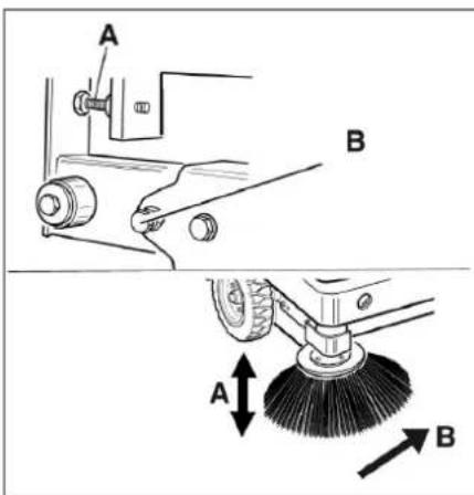
→ Set the sweeping track using the two adjusting screws.
→ Check sweeping mirror.
Adjust the side seals
△DANGER
Risk of injury!
→ Always apply the safety rod when the waste container is raised.
→ Perform the safeguarding only from outside the hazard zone.
→ Drive the waste container up and secure it with the safety rod.
→ Fold the safety rod for the high emptying up and insert it into the holder (secured).
natural_image
Close-up of a mechanical assembly with labeled parts (1 and 2), showing a red robotic arm and wiring (no readable text or symbols)1 Holder of safety rod
2 Safety rod
→ Open the side cover as described in Chapter "Replace brush roller".
→ Release the 6 wing nuts on the side holding plate.
→ Loosen 3 nuts (SW 13) on the front holding plate.
→ Press the side seal down (elongated hole) until it is about 1 to 3 mm to the floor.
→ Screw in the holding plates.
→ Repeat the procedure on the other side of the appliance.
Manually clean the dust filter
→ Switch on manual filter shake off.
Check/replace dust filter
⚠ WARNING
Risk of injury!
→ Wear a dust mask when working around the dust filter. Observe safety regulations on the handling of fine particles.
→ Clean the dust filter with the filter cleaning button.
→ Empty waste container.
1 Lock of appliance hood
2 Cover
3 Filter cover
→ Open the lock, remove the star grip screw to do this.
→ Fold cover forwards.
1 Lock, filter cover (2x)
2 Filter cover
→ Open the lock.
→ Open filter cap.
natural_image
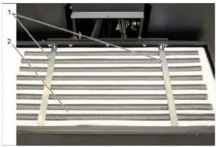
Close-up of a metallic panel with slatted structure and two numbered annotations pointing to features (no readable text or symbols)1 Cross struts
2 Dust filter
→ Check the dust filter, clean or replace if necessary.
Note
The dust filter may only be replaced by Kärcher Customer Service.
→ Insert and lock the filter cover.
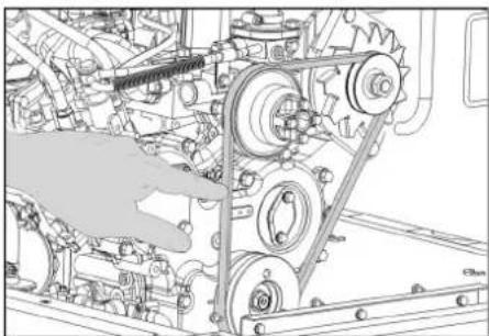
Check and adjust the V-Belt
natural_image
Technical line drawing of a mechanical assembly with gears and shafts (no text or symbols)The V-Belt must deflect approx. 7-9 mm at a pressure of 10 kg.
→ Get the V-belt tension adjusted by an authorized customer service.
Check air filter and replace, if necessary
1 L o c k
2 Air filter housing
→ Remove side panel.
→ Remove the air filter housing.
→ Replace the air filter insert.
Note: Installation position with blowout opening pointing down (see illustration).
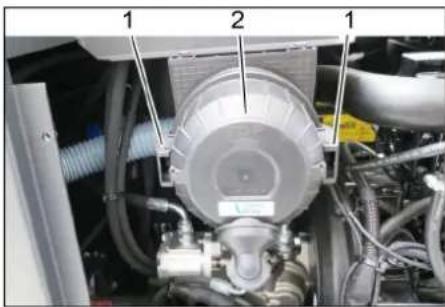
Clean the centrifugal separator
1 Wing nut
2 Centrifugal separator
→ Unscrew the wing nut from the centrifugal separator.
→ Clean the centrifugal separator.
Replacing fuses
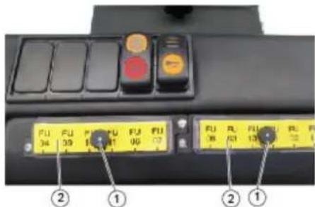
1 Lock nut
2 Cover fuse box
→ Unscrew the knurled nut.
→ Open the cover on the fuse box.
→ Check the fuses.
→ Replace defective fuses.
Note: Only use fuses with identical safety ratings.
Note: The fuse FU 01 is located in the engine compartment.
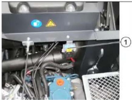
natural_image
Interior view of an industrial machine with visible wiring, valves, and control panel (no readable text or symbols)1 Fuse FU 01 (main fuse)
| FU 01* Main fuse 60 A | |
| FU 02 HornSuction blower | 20 A |
| FU 03 Multifunction display 3 A | |
| FU 04 Beacon lamp 5 A | |
| FU 05 Motor control unit 10 A | |
| FU 06 Driver cabin (optional)Wiper | 10 A |
| FU 07 LPG filling level display 5 A | |
| FU 08 Starter 10 A | |
| FU 09 Left lighting 7,5 A | |
| FU 10 Right lighting 7,5 A | |
| FU 11 Working light 10 A | |
| FU 12 Vibrator system 25 A | |
| FU 13 LPG valveBackup signal | 7,5 A |
* These fuses may only be changed by Customer Service, as it is necessary to check the device for potential faults.
Troubleshooting
| Fault Remedy | |
| Appliance cannot be started | Sit on the driver seat, the seat contact switch gets activated. |
| Press the brake pedal in order to start the engine. | |
| Charging or replacing battery | |
| Gas bottle empty - replace gas bottle. | |
| Gas removal valve closed - open the valve by turning it in anti-clockwise direction. | |
| Gas valve iced - please read the description of the gas bottle replacement procedure. | |
| Inform Kärcher Customer Service. | |
| Engine is running erratically | Clean air filter or change filter cartridge. |
| Check fuel pipes, connections and joints and maintain them if required | |
| Checking the installation position of the gas bottle: Connection or ring opening must face downwards. | |
| Inform Kärcher Customer Service. | |
| Engine is overheated Refill coolant | |
| Rinse cooler | |
| Tighten V-Belt | |
| Inform Kärcher Customer Service. | |
| Engine is running but machine is only moving slowly or is not moving at all | Release parking brake |
| Close freewheel (drive position) | |
| Move the gas lever all the way to the front (high speed). | |
| Check for trapped ribbons and strings. | |
| Inform Kärcher Customer Service. | |
| Whistling sound in the hydraulic system | Refill hydraulic fluid |
| Inform Kärcher Customer Service. | |
| Brushes are rotating slowly or not at all | Move the gas lever all the way to the front (high speed). |
| Check for trapped ribbons and strings. | |
| Inform Kärcher Customer Service. | |
| Too little or no suction power in the brush area | Check dust filter, clean or replace. |
| Inform Kärcher Customer Service. | |
| Dust gathers in the machine Adjust | the side seals |
| Switch on blower | |
| Check dust filter, clean or replace. | |
| Replace filter washers | |
| Open the container flap of the waste container. | |
| Inform Kärcher Customer Service. | |
| Sweeping unit does not pick up waste | Empty waste container |
| Check dust filter, clean or replace. | |
| Replacing roller brush | |
| Adjust sweeping track | |
| Replace sealing strips of the waste container | |
| Remove the blocking of the brush roller | |
| Open the container flap of the waste container. | |
| Inform Kärcher Customer Service. | |
| Waste container does not raise or lower | Move the gas lever all the way to the front (high speed). |
| Remove the locking support from the waste container | |
| Inform Kärcher Customer Service. | |
| The container flap of the waste container does not open. | Inform Kärcher Customer Service. |
| Operation problems with hydraulic movement parts | Inform Kärcher Customer Service. |
Technical specifications
| KM 120/250 R LPG Classic | ||
| Machine data | ||
| Drive speed, forward km/h 9 | ||
| Drive speed, reverse km/h 4 | ||
| Climbing capability (max.) % 18 | ||
| Surface cleaning performance without side brushes m | 12h 8100 | |
| Surface output with side-brush m | 12h 10800 | |
| Working width without side brushes mm 900 | ||
| Working width with side-brush mm 1200 | ||
| Protection type, drip-proof --IPX 3 | ||
| Working time with a full gas bottle | h | 4 |
| Engine | ||
| Type | -- | Kubota WG 972 GL-E3 |
| Type | -- | 3-cylinder LPG gas motor with a 3-way catalytic converter |
| CO2Emission according to the measurement procedure of EU regulation 2016/1628 (level V) | g/kWh | 844,3 |
| Cooling type | -- | Water cooling |
| Rotation direction | -- | Anticlockwise direction |
| Holes | mm 68 | |
| Hub | mm 68 | |
| Cylinder capacity | cm^3 | 740 |
| Amount of oil | l | 3,25 |
| Operating speed | 1/min | 2500 |
| Max. speed | 1/min 2500 | |
| Dry run speed | 1/min | 1300 |
| Max. power | kW/PS | 12,7 / 17,0 |
| Maximum torque at 2400 rpm | Nm | 60 |
| Oil filter | -- | Filter cartridge |
| Suction air filter | -- | Internal filter cartridge, external filter cartridge |
| Fuel type | LPGLPG mixtures of propane and butane are permitted. The propane content must be at least 90%. | |
| Tank content | 11 kg / 20 litres (replacement cylinder) | |
| Electrical system | ||
| Battery | V, Ah | 12, 52 |
| Generator, rotary current | V, Watt | 12, 150 |
| Starter | -- | Electrical starter |
| Hydraulic system | ||
| Oil quantity in the entire hydraulic system | l | 26,5 |
| Oil quantity in hydraulic tank | l | 21,2 |
| Oil grades | ||
| Engine (above 25 °C) | -- | SAE 30, SAE 10W-30, SAE 15W-40 |
| Engine (0 to 25 °C) | -- | SAE 20, SAE 10W-30, SAE 10W-40 |
| Engine (below 0 °C) | -- | SAE 10W, SAE 10W-30, SAE 10W-40 |
| Hydraulics | -- | HV 46 |
| Waste container | ||
| Max. unloading height | mm 1400 | |
| Volume of waste container l250 | ||
| Roller brush | ||
| Roller brush diameter | mm 300 | |
| Roller brush width | mm 900 | |
| Speed | 1/min | 350 |
| Sweeping track | mm 80 | |
| Side brushes | ||
| Side brush diameter mm 600 | ||
| Speed (continuous) 1/min 0 - 60 | ||
| Solid rubber tyres | ||
| Size, front -- 15-4.5x8 | ||
| Size, rear -- 15-4.5x8 | ||
| Brake | ||
| Front wheels -- mechanical | ||
| Rear wheel -- hydrostatic | ||
| Filter and vacuum system | ||
| Type -- Pocket filter | ||
| Speed | 1/min | 2800 |
| Filter surface area, fine dust filter | m^2 | 6,0 |
| Nominal vacuum, suction system | mbar | 15,5 |
| Nominal volume flow, suction system | m^3/h | 800 |
| Vibrator system | -- | Electric motor |
| Working conditions | ||
| Temperature | °C -5 and +40 | |
| Air humidity, non-condensing | % | 0 - 90 |
| Values determined as per EN 60335-2-72 | ||
| Noise emission | ||
| Sound pressure level L_pA | dB(A) | 83 |
| Uncertainty K_pA | dB(A) | 3 |
| Sound power level L_WA + Uncertainty K_WA | dB(A) | 104 |
| Machine vibrations | ||
| Hand-arm vibration value | m/s^2 | <2,5 |
| Seat | m/s^2 | 0,8 |
| Uncertainty K | m/s^2 | 0,1 |
| Dimensions and weights | ||
| Length x width x height | mm | 2082x1250x1450 |
| Right turning radius | mm | 1350 |
| Left turning radius | mm | 1350 |
| Unladen weight | kg | 851 |
| Permissible overall weight | kg 1300 | |
| Permissible front axle load | kg | 787 |
| Permissible rear axle load | kg | 513 |
| Subject to technical modifications! | ||
EU Declaration of Conformity
We hereby declare that the machine described below complies with the relevant basic safety and health requirements of the EU Directives, both in its basic design and construction as well as in the version put into circulation by us. This declaration shall cease to be valid if the machine is modified without our prior approval.
Product: Ride-on vacuum sweeper
Type: KM 120/250 R LPG Classic 1.186-001.0
Relevant EU Directives
2006/42/EC (+2009/127/EC)
2014/30/EU
2000/14/EC
Applied harmonized standards
EN 60335-1
EN 60335-2-72
EN 55012: 2007 + A1: 2009
EN 61000-6-2: 2005
EN 62233: 2008
Applied conformity evaluation method
2000/14/EC: Appendix V
Sound power level dB(A)
Measured: 102
Guaranteed: 104
Alfred Kärcher SE & Co. KG
71364 Winnenden (Germany)
Tel.: +49 7195 14-0
Fax: +49 7195 14-2212
Winnenden, 2020/01/01
The signatories act on behalf of and with the authority of the company management.

- Conner
Chairman of the Board of Management

S. Reiser
Director Regulatory Affairs & Certification
Documentation supervisor:
S. Reiser
www.kaercher.com/REACH
Garantie

1 Pompe hydraulique
2 Clé
3 É c r o u
1 Bouteille de gaz
2 Barre de sécurité
natural_image
Diagram of a mechanical device with a rotating arrow indicating rotational motion (no text or symbols)natural_image
Close-up of a mechanical assembly with three numbered components (1, 2, 3) and a textured floor panel, no visible text or symbols.1 Pédale de frein
2 Pédale "marche avant"

natural_image
Industrial machine with wheels and a handle, no visible text or symbolsnatural_image
Electrical testing setup with a control panel connected to an electronic device (no visible text or symbols)natural_image
Close-up of an internal combustion engine bay with hoses and components (no visible text or symbols)natural_image
Close-up of a mechanical engine component with labeled parts (1 and 2), no visible text or symbols beyond labelsnatural_image
Close-up of a car's side panel with visible bolts and a tire, no text or symbols present1 Clé
natural_image
Interior view of a laboratory or industrial facility with glass panels and connecting wires, no visible text or symbolsnatural_image
Abstract geometric pattern with diagonal stripes and a blue upward arrow (no text or symbols)natural_image
Close-up of a mechanical assembly with labeled parts (1 and 2), showing a red tool inserted into a blue component, no visible text or symbols.natural_image
Technical diagram of a mechanical housing or enclosure with labeled components and an arrow indicating rotation (no text or symbols present)natural_image
Technical diagram of a mechanical or electrical component with labeled parts (1 and 2), showing parallel grooves and a suspended rod (no text or symbols present)natural_image
Technical line drawing of a mechanical assembly with gears and linkages (no text or symbols)1 Ecrou papillon
natural_image
Interior view of a vehicle engine bay with visible hoses, sensors, and control panel (no readable text or symbols)1 Fusible FU 1 (fusible principal)
2006/42/CE (+2009/127/CE)
2014/30/UE
2000/14/CE
Chairman of the Board of Management

S. Reiser Director Regulatory Affairs & Certification
71364 Winnenden (Germany)
Tel.: +49 7195 14-0
Fax: +49 7195 14-2212
Winnenden, 2020/01/01
www.kaercher.com/REACH
Garanzia
1 pompa idraulica
natural_image
Diagram of a mechanical device with a rotating arrow and pipe connection (no text or symbols)natural_image
Close-up of a mechanical component with three numbered parts, showing textured surfaces and mounting holes (no visible text or symbols)1 Pedale del freno

natural_image
Black and white photo of a small industrial machine with wheels and a handle (no visible text or symbols)natural_image
Close-up of a mechanical assembly with labeled parts (1 and 2), showing a red tool inserted into a black component with wires and connectors (no readable text or symbols)natural_image
Electrical testing setup with a battery and control panel connected by wires (no visible text or symbols)natural_image
Close-up of an internal combustion engine bay with hoses and components (no visible text or symbols)natural_image
Close-up of a mechanical engine component with visible gears and hoses (no text or symbols)natural_image
Close-up of a dark vehicle's side panel with two labeled components (1 and 2), showing structural details and mounting hardware (no readable text or symbols)natural_image
Interior view of a laboratory or industrial chamber with glass panels and metal fixtures, showing internal wiring connections (no visible text or symbols)natural_image
Abstract geometric pattern with layered chevron shapes and a blue upward arrow (no text or symbols)natural_image
Close-up of a mechanical assembly with labeled parts (1 and 2), showing a red tool inserted into a blue panel and wiring (no readable text or symbols)natural_image
Technical line drawing of a mechanical housing component with labeled parts (1 and 2), showing internal structure and rotation arrow (no text or symbols beyond labels)natural_image
Technical line drawing of a mechanical assembly with gears and linkages (no text or symbols)natural_image
Interior view of a vehicle engine bay with visible hoses, valves, and control panel (no text or symbols)2006/42/CE (+2009/127/CE)
2014/30/UE
2000/14/CE

Chairman of the Board of Management

Director Regulatory Affairs & Certification
71364 Winnenden (Germany)
Tel.: +49 7195 14-0
Fax: +49 7195 14-2212
Winnenden, 2020/01/01
www.kaercher.com/REACH
Garantie


1 Hydraulische pomp
2 Sleutel
3 Moer
1 Gas files
2 Veiligheidsstang
3 Beugelsluiting
1 Hefboom stoelverstelling
2 Bestuurdersstoel
natural_image
Diagram of a mechanical device with a rotating arrow indicating rotation (no text or symbols present)1 Rempedaal
1 Bedieningshendel veegwals en zijbe-
zem
2 Bedieningshefboom vuilreservoir
3 Bedieningshendel veegwals
4 Bedieningshefboom reservoirdeksel

natural_image
Industrial robotic device with open lid and wheels (no visible text or symbols)natural_image
Close-up of a mechanical assembly with red clamping device and wiring (no visible text or symbols)natural_image
Electrical testing setup with a control panel connected to an electronic device (no visible text or symbols)natural_image
Close-up of an automotive engine bay with hoses and components (no visible text or symbols)1 Olievuldeksel (motor)
2 Oliepeilstok
natural_image
Close-up of a mechanical engine assembly with labeled parts (1 and 2), no visible text or symbols beyond labels1 Olieaftapplug
2 Motoroliefilter
1 Koelmiddel-compensatievat
natural_image
Close-up of a dark vehicle's side panel with bolt holes and a tire, no visible text or symbols1 Sleutel
2 Zijbekleding
natural_image
Interior view of a stainless steel enclosure with visible structural lines and components (no text or symbols)1 Houdbeugel
2 Vleugelmoer
natural_image
Abstract geometric pattern with layered chevron shapes and a blue upward arrow (no text or symbols)→ Handmatige filterreiniging inschakelen.
Stoffilter controleren / vervangen
⚠ WAARSCHUWING
Verwondingsgevaar!
1 Vergrendeling apparaatkap
2 Apparaatkap
3 Filterafdekking
natural_image
Technical line drawing of a mechanical housing component with labeled parts (1 and 2), showing internal components and an arrow indicating rotation or movement (no text or symbols beyond labels)1 Sluiting, filterafdekking (2x)
2 Filterafdekking
→ Sluiting openen.
→ Filterafdekking openen.
natural_image
Close-up of a mechanical component with two labeled parts (1 and 2) and diagonal lines, no visible text or symbols.1 Dwarsbalk
2 Stoffilter
→ Controleer de stoffilter, reinig of vervang hem indien nodig.
Tip
natural_image
Technical line drawing of a mechanical assembly with gears and linkages (no text or symbols)1 Vleugelmoer
2 Centrifugaalseparator
natural_image
Interior view of a vehicle engine bay with visible wiring, sensors, and control panel (no text or symbols)
Chairman of the Board of Management

Director Regulatory Affairs & Certification
71364 Winnenden (Germany)
Tel.: +49 7195 14-0
Fax: +49 7195 14-2212
Winnenden, 2020/01/01
www.kaercher.com/REACH
Garantía
1 Tornillo
2 | | a v e
1 Bomba hidráulica
2 l l a v e
3 Tuerca
1 Botella de gas
2 Barra de seguro
natural_image
Diagram of a medical or laboratory procedure showing a device with tubing and a circular component, no text or symbols present.1 Pedal del freno
2 Pedal acelerador "avance"
natural_image
Industrial machine with wheels and a mounted panel, no visible text or symbolsnatural_image
Electrical testing setup with a battery pack and connected wiring (no visible text or symbols)natural_image
Close-up of an internal combustion engine bay with hoses and components (no visible text or symbols)natural_image
Close-up of a mechanical engine component with labeled parts (1 and 2), no visible text or symbols beyond labels1 Recipiente compensador de refrigerante
natural_image
Close-up of a car's front panel with visible bolts and a tire, no text or symbols presentnatural_image
Interior view of a stainless steel industrial chamber with numbered components (no visible text or symbols)natural_image
Diagram of a layered structure with a blue upward arrow at the base (no text or symbols)natural_image
Close-up of a mechanical assembly with labeled parts (1 and 2), showing a red tool inserted into a housing (no readable text or symbols)natural_image
Technical diagram of a mechanical housing or enclosure with labeled components and an arrow indicating rotation (no text or symbols present)natural_image
Close-up of a mechanical component with two labeled parts (1 and 2) and diagonal lines, no visible text or symbols.natural_image
Technical line drawing of a mechanical assembly with gears and linkages (no text or symbols)1 Tuerca de mariposa
2 Separador centrífugo
natural_image
Interior view of a vehicle engine bay with visible wiring, sensors, and control panel (no readable text or symbols)1 Fusible FU 1 (fusible principal)
2006/42/CE (+2009/127/CE)
2014/30/UE
2000/14/CE
71364 Winnenden (Germany)
Tel.: +49 7195 14-0
Fax: +49 7195 14-2212
Winnenden, 2020/01/01
www.kaercher.com/REACH
Garantia
1 Bomba hidráulica
2 Chaves
3 Porca
1 Garrafa de gás
2 Barra de segurança
3 Tranca de alavanca
natural_image
Diagram of a mechanical device with a rotating arrow indicating rotational motion (no text or symbols)1 Pedal do travão
1 Alavanca de comando da escova cilíndrica de varredura e vassoura lateral
2 Alavanca de comando do colector do lixo varrido
3 Alavanca de comando da escova cilíndrica de varredura
4 Alavanca de comando da tampa do recipiente
Alavanca de comando da escova cilíndrica de varredura e vassoura lateral
→ Alavanca de comando (1) para a frente: Escova cilíndrica de varredura ligada, baixar a vassoura lateral e ligar.
→ Alavanca de comando (1) para trás: Escova cilíndrica de varredura ligada.
Alavanca de comando do colector do lixo varrido
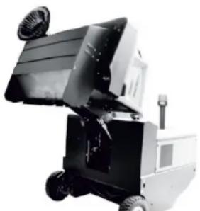
natural_image
Black and white photo of a small industrial machine with wheels and a handle (no visible text or symbols)natural_image
Electrical testing setup with a battery pack and connected wiring (no visible text or symbols)natural_image
Close-up of an internal combustion engine bay with hoses and components (no visible text or symbols)natural_image
Close-up of a mechanical engine component with labeled parts (1 and 2), no visible text or symbols beyond labels→ Limpar as lamelas do radiador.
natural_image
Close-up of a dark vehicle's side panel with visible bolts and a tire, no text or symbols present1 Chaves
2 Revestimento lateral
natural_image
Interior view of a mechanical or industrial enclosure with numbered components (1, 2, 3) and connecting wires, no visible text or symbols.natural_image
Abstract geometric pattern with layered chevron shapes and a blue upward arrow (no text or symbols)→ Ligar a limpeza do filtro manual.
natural_image
Technical line drawing of a mechanical housing or enclosure with labeled components (1, 2), showing internal structure and rotation arrow (no text or symbols beyond labels)natural_image
Close-up of a mechanical component with two labeled parts (1 and 2) and a diagonal line, no visible text or symbols.1 Travessas
2 Filtro do pó
natural_image
Technical line drawing of a mechanical assembly with gears and linkages (no text or symbols)1 Fecho
1 Porca de orelhas
2 Separador por força centrífuga
→ Desaparafusar a porca de orelhas no separador por força centrífuga.
→ Limpar o separador por força centrífuga.
natural_image
Interior view of an industrial vehicle showing hoses, valves, and a control panel (no readable text or symbols)
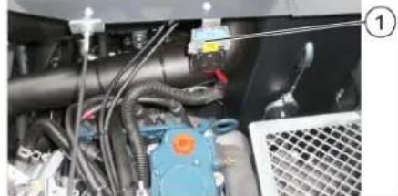
natural_image
Close-up of industrial machinery components with hoses and valves (no visible text or symbols)2006/42/CE (+2009/127/CE)
2014/30/UE
2000/14/CE
Chairman of the Board of Management

Director Regulatory Affairs & Certification
71364 Winnenden (Germany)
Tel.: +49 7195 14-0
Fax: +49 7195 14-2212
Winnenden, 2020/01/01
Generelle henisninger ..... DA 1
www.kaercher.com/REACH
Garanti
1 Hydraulikpumpe
2 N ∅ g l e
3 M ø t r i k
1 Gasflaske
2 Sikringsstang
3 Bøjlelås
natural_image
Diagram of a mechanical device with rotating arm and tubing, no text or symbols present1 Bremsepedal
2 Kørepedal "frem"
3 Kørepedal "bak"
→ Skub omstilleren til motorens omdrejningstal helt fremad (driftsomdrejningstal).
→ Trykke bremsepedalen og hold den ned.
→ Løsn stopbremsen.
Kør frem
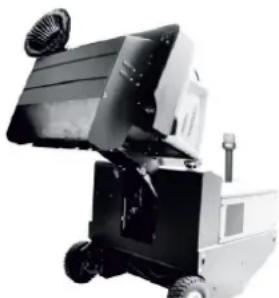
natural_image
Black and white photo of a small industrial machine with wheels and a fan (no visible text or symbols)1 Plus pol
2 Polafdækning
3 Minuspol
natural_image
Electrical testing setup with battery pack and control panel connected by wires (no visible text or symbols)1 Holder sikringsstang
natural_image
Close-up of an internal combustion engine bay with hoses and components (no visible text or symbols)1 Oliepåfyldningsdæksel (motor)
2 Oliemålepind
natural_image
Close-up of a mechanical engine component with labeled parts (1 and 2), no visible text or symbols beyond labelsnatural_image
Close-up of a dark metal vehicle's side panel with a tire and two small components, no visible text or symbols.1 N ø g l e
2 Sideskærme
natural_image
Interior view of a large industrial or laboratory chamber with visible structural lines and components (no text or symbols)1 Holdebøjle
2 Vingemøtrik
3 Tætning i siden
natural_image
Diagram of a layered structure with a blue upward arrow, no text or symbols presentnatural_image
Close-up of a mechanical assembly with labeled parts (1 and 2), showing a red tool inserted into a black panel and wiring (no readable text or symbols)1 Holder sikringsstang
2 Sikringsstang
natural_image
Technical line drawing of a mechanical housing component with labeled parts (1 and 2), showing internal components and an arrow indicating rotation or movement (no text or symbols beyond labels)natural_image
Close-up of a metallic grate with two labeled components (1 and 2), no visible text or symbols on the grate itself.natural_image
Technical line drawing of a mechanical assembly with gears and linkages (no text or symbols)1 Vingemøtrik
2 Skillecentrifuge
→ Skru vingemøtrikken på skillecentrifugen af.
→ Rens skillecentrifugen.
natural_image
Interior view of an industrial vehicle showing hoses, valves, and a control panel (no readable text or symbols)1 Sikring FU 1 (hovedsikring)
| FU 01* Hovedsikring 60 A | |
| FU 02 Signalhorn Sugeturbiner | 20 A |
| FU 03 Multifunktionsdisplay 3 A | |
| FU 04 Rundomkring-advarselslys | 5 A |
| FU 05 Motor-kontrolenhed 10 A | |
| FU 06 Beskyttelsestag (option)Visker | 10 A |
| FU 07 LPG-påfyldningsviser 5 A | |
| FU 08 Starter 10 A | |
| FU 09 Belysning venstre | 7,5 A |
| FU 10 Belysning højre | 7,5 A |
| FU 11 Arøejdsbelysning | 10 A |
| FU 12 Vibratorsystem | 25 A |
| FU 13 LPG-ventilBaksignal | 7,5 A |
2006/42/EF (+2009/127/EF)
2014/30/EU
2000/14/EF
H. Jenner Chairman of the Board of Management

S. Reiser Director Regulatory Affairs & Certification
71364 Winnenden (Germany)
Tel.: +49 7195 14-0
Fax: +49 7195 14-2212
Winnenden, 2020/01/01
Generelle merknader.....NO 1
Feilretting....NO 13
Tekniske data ..... NO 14
EU-samsvarserklæring ..... NO 15
www.kaercher.com/REACH
Garanti
Fare for forbrenning!
5 Motor innsugingsluft
6 Varsellampe parkeringsbrems aktivert
1 hydraulikkpumpe
2 Nøkkel
3 M u t t e r
1 Gassflaske
2 Sikringsstang
3 B ø y l e l ä s
→ Løsne skruen på sikringsstangen og sving stangen til side.
→ Skifte gassflaske.
→ Skru av beskyttelseshette på ventilen på gassflasken.
→ Lukk läsebøylen.
1 Hendel setejustering
2 F ø r e r s e t e
natural_image
Diagram of a medical or laboratory procedure showing a device with tubing and a circular component, no text or symbols present.→ Ta plass på førersetet.
→ Lås parkeringsbremsen (11).
→ Skyv motorturtallsjusteringen (10) 1/3 forover.
Starte motoren
1 Bremsepedal
2 Kjørepedal "forover"
1 Betjeningsspak feievals og sidekost
2 Betjeningsspak feieavfallsbeholder
3 Betjeningsspak feievals
4 Betjeningsspak beholderklaff
natural_image
Black and white photo of a wheeled industrial machine with wheels and a fan (no visible text or symbols)→ Løfte feievals og sidekost med betjeningsspakene: Betjeningsspak 1 i midten og betjeningsspak 3 forover.
→ Lukk beholderklaffen, dertil trekkes betjeningsspaken (4) bakover.
→ Løft feieavfallsbeholderen, dertil trekkes betjeningsspaken til feieavfallsbeholderen (2) bakover.
→ Kjør langsomt frem til samlebeholderen.
→ Trekk til holdebremsen.
→ Åpne beholderklaffen, dertil trykkes betjeningsspaken til beholderklaffen (4) fremover og feieavfallsbeholderen tømmes.
→ Lukk beholderklaffen, dertil trekkes betjeningsspaken til beholderklaffen (4) bakover helt til den er vippet i endepositionen.
→ Løsne parkeringsbremsen.
→ Kjør langsomt bort fra samlebeholder.
→ Senk feieavfallsbeholderen i endepositionen, dertil trekkes betjeningsspaken (2) fremover
Slå maskinen av
→ Løfte feievals og sidekost med betjenningsspakene: Betjeningsspak 1 i midten og betjeningsspak 3 forover.
→ Lukk beholderklaffen, dertil trekkes betjeningsspaken (4) bakover.
→ Trekk motorturtallsreguleringen helt bakover.
→ Bremspedal trykkes inn og holdes inn-trykt.
→ Trekk til holdebremsen.
→ Vri tenningsnøkkelen til "0" og trekk den ut.
Transport
⚠️FARE
Transportskader!
natural_image
Close-up of a mechanical assembly with red clamping device and wiring (no visible text or symbols)1 Holder sikringsstang
2 Sikringsstang
natural_image
Electrical testing setup with a battery pack and connected circuit board (no visible text or symbols)1 Holder sikringsstang
Fare for forbrenning!
→ La motoren avkjøles.
natural_image
Close-up of an internal combustion engine bay with hoses and components (no visible text or symbols)natural_image
Close-up of a mechanical assembly with labeled parts (1 and 2), no visible text or symbols beyond labels1 Oljetappeskrue
2 Motorljefilter
natural_image
Close-up of a dark vehicle's side panel with a tire and a small object, no visible text or symbols1 Nøkkel
2 Sidekledning
→ Kjør feieavfallsbeholderen opp og sikre den med sikringsstang.
→ Åpne sidekledning med nøkkel.
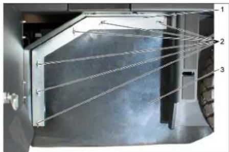
natural_image
Interior view of a laboratory or industrial chamber with numbered components (1, 2, 3) and no visible text or symbols.natural_image
Diagram of a layered structure with an upward arrow, no text or symbols present→ Kontroller dekktrykket.
→ Slå av sugevifte.
→ Kjør feiemaskinen på et jevnt og glatt underlag, som er synlig dekket av støv eller kritt.
→ Betjeningsspak feievals og sidekost (1)
bakover: Feievals på.
Betjeningsspak feievals (3) bakover:
Feievalsen senkes.
→ La feievalsen gå i ca. 10 sekunder.
→ Betjeningsspak feievals og sidekost (1) i midten.
Betjeningsspak feievals (3) forover: Feievalsen løftes.
→ Rygg maskinen bort.
→ Kontroller feiemønster.

Formen av feiemønsteret skal danne en li-kesidet firkant med bredde 80-85 mm.
natural_image
Close-up of a mechanical assembly with labeled parts (1 and 2), showing internal components like a red tool and wiring (no readable text or symbols)1 Holder sikringsstang
2 Sikringsstang
natural_image
Technical diagram of a mechanical housing or enclosure with labeled components and an arrow indicating rotation (no text or symbols present)1 Lås, filterdeksel (2x)
2 Filterdeksel
→ Åpne läs.
→ Åpne filterdeksel.
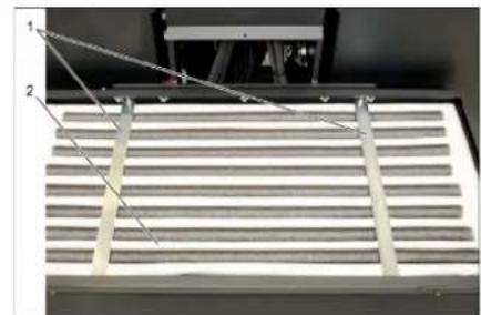
natural_image
Close-up of a metallic grate with two labeled components (1 and 2), no visible text or symbols on the grate itself.1 T v e r r s t a g
2 Støvfilter
natural_image
Technical line drawing of a mechanical assembly with gears and linkages (no text or symbols)1 Vingemutter
2 Sentrifugalseparator
natural_image
Interior view of an industrial vehicle showing hoses, valves, and a control panel (no readable text or symbols)1 Sikring FU 1 (hovedsikring)
| FU 01* Hovedsikring 60 A | |
| FU 02 HornSugevifte | 20 A |
| FU 03 Multifunksjonsindikator 3 A | |
| FU 04 Roterende varsellys 5 A | |
| FU 05 Motorkontrollenhet 10 A | |
| FU 06 Førerhytte (tilleggsut-styr)Vindusvisker | 10 A |
| FU 07 LPG-påfyllingsnivå 5 A | |
| FU 08 Starter 10 A | |
| FU 09 Belysning venstre 7,5 A | |
| FU 10 Belysning høyre | 7,5 A |
| FU 11 Arbeidslys | 10 A |
| FU 12 Vibratorsystem | 25 A |
| FU 13 LPG-ventilRyggesignal | 7,5 A |
* Disse sikringene må kun byttes av kundeservice, fordi det blir nødvendig å kontrollere apparatet for eventuelle feil.
Feilretting
2006/42/EF (+2009/127/EF)
2014/30/EU
2000/14/EF
2000/14/EF: Vedlegg V
Lydeffektnivå dB(A)
Målt: 102
Garantert: 104
H. Jenner Chairman of the Board of Management

S. Reiser Director Regulatory Affairs & Certification
71364 Winnenden (Germany)
Tel.: +49 7195 14-0
Fax: +49 7195 14-2212
Winnenden, 2020/01/01
www.kaercher.com/REACH
Garanti
natural_image
Diagram of a mechanical device with rotating arm and pipe connection (no text or symbols)1 Bromspedal
2 Körpedal "framåt"
3 Körpedal "bakåt"
→ Starta fläkt.
→ Vid ytrengöring
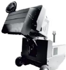
natural_image
Black-and-white photo of a small industrial machine with wheels and a side-mounted fan (no visible text or symbols)natural_image
Close-up of a mechanical assembly with labeled parts (1 and 2), showing a red tool inserted into a blue component, no visible text or symbols.natural_image
Electrical testing setup with battery pack and wiring, no visible text or symbolsnatural_image
Close-up of an automotive engine bay with hoses and components, no visible text or symbols1 Oljepåfyllningslock (motor)
2 Oljesticka
natural_image
Close-up of a mechanical engine component with labeled parts (1 and 2), showing internal gears, springs, and hoses (no readable text or symbols beyond labels)natural_image
Close-up of a dark vehicle's side panel with a tire and two labeled components (no visible text or symbols)natural_image
Interior view of a laboratory or industrial chamber with labeled components (no visible text or symbols)natural_image
Abstract geometric pattern with diagonal stripes and a blue upward arrow (no text or symbols)natural_image
Close-up of a mechanical assembly with numbered components (1 and 2) and red tool handle, no visible text or symbols→ Välj manuell filterrengöring.
Kontrollera/byta dammfilter
△VARNING
Risk för skada!
natural_image
Close-up of a metallic rack with two labeled components (1 and 2), no visible text or symbols on the rack itself.1 T v ä r s t r ä v a
2 Dammfilter
natural_image
Technical line drawing of a mechanical assembly with gears and linkages (no text or symbols)1 V i n g m u t t e r
2 Centrifugalkraftsavskiljare
→ Skruva loss vingmuttern på centrifugal-kraftsavskiljaren.
→ Rengör centrifugalkraftsavskiljaren.
Byta ut säkringar

1 Räfflade muttrar
natural_image
Interior view of an industrial vehicle showing hoses, valves, and a mesh fan (no visible text or symbols)
Chairman of the Board of Management

S. Reiser
Director Regulatory Affairs & Certification
71364 Winnenden (Germany)
Tel.: +49 7195 14-0
Fax: +49 7195 14-2212
Winnenden, 2020/01/01
www.kaercher.com/REACH
Takuu


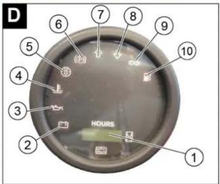
1 Hydraulipumppu
2 A v a i n
3 M u t t e r i
natural_image
Diagram of a medical or laboratory procedure showing a device with tubing and a circular component, no text or symbols present.1 Jarrupoljin

natural_image
Black and white photo of a small industrial machine with wheels and a handle (no visible text or symbols)1 Varmistustangon pidike
2 Jarrunestesäiliö
3 Sulkukansi
natural_image
Close-up of an automotive engine bay with hoses and components (no visible text or symbols)natural_image
Close-up of a mechanical assembly with labeled parts (1 and 2), no visible text or symbols beyond labels1 Öljynpoistotulppa
natural_image
Close-up of a dark vehicle's side panel with two labeled components (1 and 2), showing no visible text or symbols.1 A v a i n
2 Sivuverhous
natural_image
Interior view of a stainless steel industrial chamber with numbered components (no visible text or symbols)natural_image
Diagram of a folded or layered structure with a blue upward arrow at the bottom (no text or symbols)natural_image
Close-up of a mechanical assembly with labeled parts (1 and 2), showing a red tool inserted into a component, surrounded by cables and a metallic frame (no text or symbols visible)1 Varmistustangon pidike
2 Varmistustanko
natural_image
Technical diagram of a mechanical housing component with labeled parts (1, 2) and an arrow indicating rotation or movement (no text or symbols beyond labels)natural_image
Close-up of a mechanical component with two labeled parts (1 and 2) and diagonal lines indicating alignment or measurement, no readable text or symbols present.1 Poikittaistuet
2 Pölysuodatin
natural_image
Technical line drawing of a mechanical assembly with gears and linkages (no text or symbols)1 Siipimutteri
2 Keskipakoiserotin
natural_image
Interior view of a vehicle engine bay with visible hoses, valves, and control panel (no text or symbols)1 Sulake FU 1 (pääsulake)
Chairman of the Board of Management

Director Regulatory Affairs & Certification
71364 Winnenden (Germany)
Tel.: +49 7195 14-0
Fax: +49 7195 14-2212
Winnenden, 2020/01/01
www.kaercher.com/REACH
Εγγύηση
1 K o x λ i a s
2 Κλειδί
natural_image
Diagram of a medical or surgical procedure showing a valve inserted into a tube, with an arrow indicating direction (no text or symbols present)natural_image
Close-up of a mechanical assembly with metal components and a textured floor (no visible text or symbols)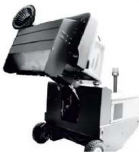
natural_image
Industrial robotic device with wheels and a mounted panel (no visible text or symbols)natural_image
Electrical testing setup with battery pack and control panel connected by wires (no visible text or symbols)natural_image
Close-up of an internal combustion engine bay with hoses and components (no visible text or symbols)natural_image
Close-up of a mechanical engine component with labeled parts (1 and 2), showing internal gears, springs, and hoses (no readable text or symbols beyond labels)natural_image
Close-up of a dark metal vehicle's side panel with a tire and two small components, no visible text or symbols.natural_image
Interior view of a server rack with visible mesh connections and ventilation ducts (no text or symbols)natural_image
Diagram of a layered structure with a blue upward arrow, no text or symbols presentnatural_image
Close-up of a mechanical assembly with labeled parts (1 and 2), showing a red tool inserted into a housing (no text or symbols visible)natural_image
Technical diagram of a mechanical component with two labeled parts (1 and 2), showing parallel grooves and a central rod (no text or symbols present)1 Εγκάρσιο στιλίδιο
2 Φίλτρο σκόνης
natural_image
Technical line drawing of a mechanical assembly with gears and shafts (no text or symbols)natural_image
Industrial equipment setup with pipes, valves, and warning symbols (no readable text or labels)
Chairman of the Board of Management

S. Reiser
Director Regulatory Affairs & Certification
71364 Winnenden (Germany)
Tel.: +49 7195 14-0
Fax: +49 7195 14-2212
Winnenden, 2020/01/01
www.kaercher.com/REACH
Garanti


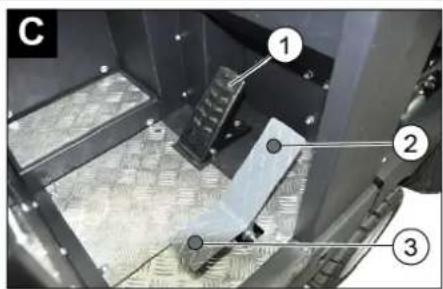
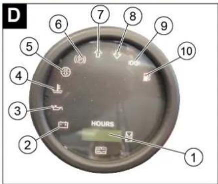
1 Hidrolik pompa
2 Anahtar
3 Somun
1 Koltuk ayarlama kolu
2 Sürücü koltuğu
natural_image
Diagram of a mechanical device with hoses and a rotating arrow, no text or symbols present1 Fren pedali
2 Gaz pedali "ileri"
3 Gaz pedali "geri"
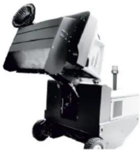
natural_image
Black and white photo of a small industrial machine with wheels and a mounted panel (no visible text or symbols)natural_image
Close-up of a mechanical assembly with labeled parts (1 and 2), showing a red tool inserted into a housing component (no readable text or symbols)natural_image
Electrical testing setup with a battery pack and connected circuit board (no visible text or symbols)natural_image
Close-up of an automotive engine bay with hoses and components (no visible text or symbols)natural_image
Close-up of a mechanical engine component with numbered parts (1 and 2), no visible text or symbols beyond labelsnatural_image
Close-up of a dark metal vehicle's side panel with a tire and numbered annotation (no readable text or symbols)natural_image
Interior view of a modern industrial or laboratory facility with glass panels and structural beams (no visible text or symbols)1 Tutma kolu
2 Kanatlı somun
3 Yan conta
natural_image
Abstract geometric pattern with layered triangular shapes and a blue upward arrow (no text or symbols)natural_image
Close-up of a mechanical assembly with labeled parts (1 and 2), showing a red tool inserted into a black panel and connected cables (no readable text or symbols)natural_image
Interior view of a slatted industrial or filtration unit with labeled components (no readable text or symbols)1 Çapraz kiriş
2 Toz filtresi
natural_image
Technical line drawing of a mechanical assembly with gears and linkages (no text or symbols)natural_image
Interior view of an industrial machine with visible wiring, valves, and control panel (no readable text or symbols)1 Sigorta FU 1 (ana sigorta)

Chairman of the Board of Management
S. Reiser
Director Regulatory Affairs & Certification
71364 Winnenden (Germany)
Tel.: +49 7195 14-0
Fax: +49 7195 14-2212
Winnenden, 2020/01/01
www.kaercher.com/REACH
Гарантия


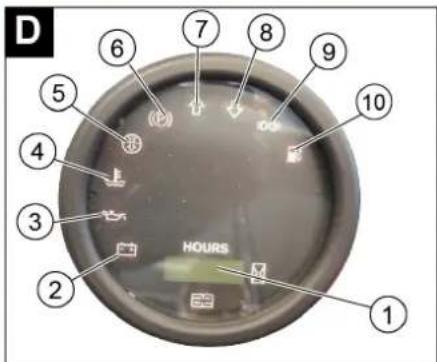
natural_image
Diagram of a medical or surgical procedure showing a valve inserted into a circular component, with no visible text or symbols.1 Педаль тормоза

natural_image
Black and white photo of a wheeled industrial machine with wheels and a handle (no visible text or symbols)natural_image
Close-up of a mechanical assembly with labeled parts (1 and 2), showing a red tool inserted into a black component with cables and connectors (no readable text or symbols)natural_image
Electrical testing setup with a battery pack and connected circuit board (no visible text or symbols)natural_image
Close-up of an internal combustion engine bay with hoses and components (no visible text or symbols)natural_image
Close-up of a mechanical engine component with labeled parts (1 and 2), no visible text or symbols beyond labelsnatural_image
Close-up of a dark vehicle's side panel with two numbered components and a tire, no visible text or symbols.1 Ключ
2 Боковая обшивка
natural_image
Interior view of a mechanical or industrial enclosure with visible structural lines and internal components (no text or symbols)1 С к о б а
2 Барашковая гайка
natural_image
Abstract geometric pattern with layered chevron shapes and a blue upward arrow (no text or symbols)natural_image
Technical line drawing of a mechanical housing component with labeled parts (1, 2) and an arrow indicating rotation or movement (no text or symbols beyond labels)natural_image
Technical diagram of a mechanical component with labeled parts (1, 2) and diagonal lines indicating alignment or measurement points (no readable text or symbols)natural_image
Technical line drawing of a mechanical assembly with gears and springs (no text or symbols)natural_image
Interior view of a vehicle showing internal components including hoses, valves, and a control panel (no readable text or symbols)Chairman of the Board of Management

S. Reiser Director Regulatory Affairs & Certification
71364 Winnenden (Germany)
Tel.: +49 7195 14-0
Fax: +49 7195 14-2212
Winnenden, 2020/01/01
www.kaercher.com/REACH
Garancia


1 Hidraulikaszivattyú
2 K u l c s -
3 A n y a
natural_image
Diagram of a mechanical valve assembly with rotating arrow and pipe connection (no text or symbols)1 Fékpedál
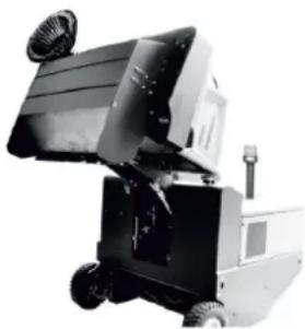
natural_image
Black and white photo of a small industrial machine with wheels and a handle (no visible text or symbols)natural_image
Close-up of a mechanical assembly with labeled parts (1 and 2), showing a red lever handle and wiring (no readable text or symbols)natural_image
Electrical circuit setup with a battery pack and connected wires (no visible text or symbols)natural_image
Close-up of an automotive engine bay with hoses and components (no visible text or symbols)1 Olajbetöltö fedele (motor)
natural_image
Close-up of a mechanical engine assembly with labeled parts (1 and 2), no visible text or symbols beyond labelsnatural_image
Close-up of a vehicle's side panel with a tire and numbered component (no visible text or symbols)1 Kulcs-
2 Oldalburkolat
natural_image
Interior view of a stainless steel enclosure with visible ductwork and insulation (no text or symbols)natural_image
Diagram of a layered structure with an upward arrow, no text or symbols presentnatural_image
Close-up of a mechanical assembly with labeled parts (1 and 2), showing a red tool inserted into a gray panel and wiring (no readable text or symbols)natural_image
Technical line drawing of a mechanical housing component with labeled parts (1 and 2), showing internal components and an arrow indicating rotation or movement (no text or symbols beyond labels)natural_image
Technical diagram of a mechanical component with labeled parts (1 and 2), showing a grid-like structure and alignment lines (no readable text or symbols)natural_image
Technical line drawing of a mechanical assembly with gears and springs (no text or symbols)natural_image
Interior view of a mechanical or industrial device with visible pipes, valves, and a mesh grille (no readable text or symbols)Chairman of the Board of Management

Director Regulatory Affairs & Certification
71364 Winnenden (Germany)
Tel.: +49 7195 14-0
Fax: +49 7195 14-2212
Winnenden, 2020/01/01
www.kaercher.com/REACH
Záruka


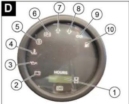
natural_image
Diagram of a medical or laboratory procedure showing a device with tubing and a circular component, no text or symbols present.1 Brzdový pedál

natural_image
Black and white photo of a small industrial machine with wheels and a handle (no visible text or symbols)natural_image
Electrical testing setup with a power supply unit connected to a device with wires (no visible text or symbols)natural_image
Close-up of a car engine bay with hoses and components, no visible text or symbolsnatural_image
Close-up of a mechanical engine component with labeled parts (1 and 2), no visible text or symbols beyond labelsnatural_image
Close-up of a dark metal vehicle's side panel with a tire and two small components, no visible text or symbols.1 K I i č
2 Boční obložení
natural_image
Interior view of a stainless steel industrial chamber with visible ductwork and internal structure (no text or symbols)1 Přidržovací třmen
2 Křídlová matice
3 Boční těsnění
natural_image
Diagram of a layered structure with a blue upward arrow, no text or symbols presentnatural_image
Close-up of a mechanical assembly with labeled parts (1 and 2), showing a red tool inserted into a blue component, connected to wires and a metallic bracket (no readable text or symbols)1 Zajištění kapoty
2 Kryt prístroje
3 Kryt filtru
natural_image
Close-up of a metallic rack with two metal supports and a white slatted surface, no visible text or symbols1 Příčné vzpěry
2 Prachový filtr
natural_image
Technical line drawing of a mechanical assembly with gears and linkages (no text or symbols)1 Křídlová matice
natural_image
Close-up of industrial machinery components with visible wiring and a warning symbol (no readable text or labels)2006/42/ES (+2009/127/ES)
2014/30/EU
2000/14/ES
71364 Winnenden (Germany)
Tel.: +49 7195 14-0
Fax: +49 7195 14-2212
Winnenden, 2020/01/01
Splošna navodila ..... SL 1
Varstvo okolja ..... SL 1
Garancija ..... SL 1
Pribor in nadomestni deli SL 1
Simboli v navodilu za obrato- vanje ..... SL 1
Simboli na napravi ..... SL 1
Namenska uporaba ..... SL 2
Predvidljiva napačna upora-
ba. SL 2
Primerne podlage.....SL 2
Varnostna navodila ..... SL 2
www.kaercher.com/REACH
Garancija
1 Vijak
2 Ključ
→ Izvijte vijak.
→ Odstranite ključ.

1 Plinska jeklenka
2 Varnostni drog
3 Zapiralo z vezico
natural_image
Close-up of a mechanical component with labeled parts 1 and 2, showing no readable text or symbols.natural_image
Diagram of a medical or laboratory procedure showing a device with tubing and a circular component, no text or symbols present.1 Zavorni pedal
2 Vozni pedal „naprej"
3 Vozni pedal „vzvratno"

natural_image
Black and white photo of a small industrial machine with wheels and a handle (no visible text or symbols)natural_image
Close-up of a mechanical assembly with labeled parts (1 and 2), showing a red tool inserted into a blue component, no visible text or symbols.natural_image
Electrical testing device with a grid display and connected cables (no visible text or symbols)1 Držalo varnostnega droga
natural_image
Close-up of an automotive engine bay with visible hoses and components (no text or symbols)natural_image
Close-up of a mechanical engine component with labeled parts (1 and 2), showing internal gears, springs, and hoses (no readable text or symbols beyond labels)natural_image
Close-up of a dark metal panel with bolt holes and a tire, no visible text or symbols1 Ključ
2 Stranska obloga
natural_image
Interior view of a stainless steel enclosure with visible wiring and structural supports (no text or symbols)1 Držalna palica
2 Krilata matica
3 Stransko tesnilo
→ Odvijte krilate matice.
→ Snemite držalno palico.
→ Stransko tesnilo sklopite navzven.
→ Izvijte pritreditveni vijak nosilca pometalne-ga valja in nosilec zasukajte navzven.
→ Izvlecite pometalni valj.
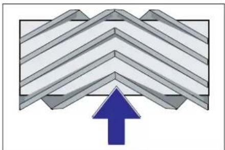
natural_image
Abstract geometric pattern with layered chevron shapes and a blue upward arrow (no text or symbols)Vgradni položaj pometalnega valja v smeri vožnje (tloris)
Opozorilo: Pri vgradnji novega pometalne- ga valja pazite na položaj krtačnega na- stavka.
→ Vstavite nov pometalni valj. Zareze pometalnega valja morajo biti nataknjene na utore nasproti ležeče nihalke.
Opozorilo: Po vgradnji novega pometalne-ga valja je potrebno površino pometanja na novo nastaviti.
Preverjanje in nastavljanje površine pometanja pometalnega valja
Opozorilo: Pometalna površina je tovarniško nastavljena na 80 mm, ob obrabi po-metalnih valjev jo je mogoče brezstopenjsko nastaviti.
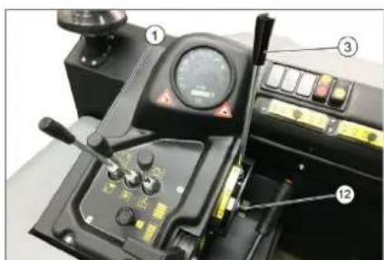
natural_image
Close-up of a mechanical assembly with labeled parts (1 and 2), showing a red tool inserted into a component, no readable text or symbols present.1 Držalo varnostnega droga
2 Varnostni drog
1 Zapiralo, pokrov filtra (2x)
2 Pokrov filtra
→ Odprite zapiralo.
→ Odprite pokrov filtra.
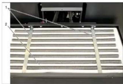
natural_image
Technical diagram of a mechanical component with two labeled parts (1 and 2), showing internal structure and alignment lines (no text or symbols beyond labels)1 Prečne opore
2 Filter za prah
→ Preverite filter za prah, po potrebi ga očistite ali zamenjajte.
Napotek
natural_image
Technical line drawing of a mechanical assembly with gears and linkages (no text or symbols)Klinasti jermen mora pri tlaku 10 kg popustiti ca. 7-9 mm.
1 Krilata matica
2 Ločevalnik s centrifugalno silo
→ Odvijte krilato matico na ločevalniku s centrifugalno silo.
→ Očistite ločevalnik s centrifugalno silo.
Menjava varovalk
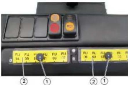
1 Narebričena matica
2 Pokrov omarice z varovalkami
→ Izvijte narebričene matice.
→ Odprite pokrov na omarici z varovalkami.
→ Preverite varovalke.
→ Zamenjajte defektne varovalke.
natural_image
Interior view of an industrial vehicle showing hoses, valves, and a control panel (no visible text or symbols)1 Varovalka FU 1 (glavna varovalka)
| FU 01* Glavna varovalka 60 A | |
| FU 02 TrobljaSesalni ventilator | 20 A |
| FU 03 Multifunkcijski prikaz 3 A | |
| FU 04 Vrteča opozorilna luč 5 A | |
| FU 05 Kontrolna enota motor-ja | 10 A |
| FU 06 Voznikova kabina (Op-cija)Brisalec | 10 A |
| FU 07 Prikaz stanja polnosti za UNP | 5 A |
| FU 08 Zaganjač 10 A | |
| FU 09 Osvetlitev levo 7,5 A | |
| FU 10 Osvetlitev desno 7,5 A | |
| FU 11 Delovna osvetlitev 10 A | |
| FU 12 Sistem vibratorja 25 A | |
| FU 13 Ventil za UNPSignal vzvratne vožnje | 7,5 A |
2006/42/ES (+2009/127/ES)
2014/30/EU
2000/14/ES
71364 Winnenden (Germany)
Tel.: +49 7195 14-0
Fax: +49 7195 14-2212
Winnenden, 2020/01/01
Podpisniki ravnajo po navodilih in s pooblastilom uprave.

Chairman of the Board of Management
Director Regulatory Affairs & Certification
www.kaercher.com/REACH
Gwarancja


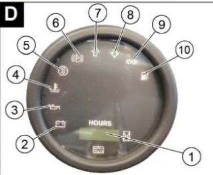
natural_image
Close-up of a mechanical component with labeled parts 1 and 2, showing no readable text or symbols.natural_image
Diagram of a mechanical device with a rotating arrow indicating rotational motion (no text or symbols)natural_image
Close-up of a mechanical assembly with numbered components (1, 2, 3) and textured surface, no visible text or symbols.1 Pedal hamulca
2 Pedal jazdy „do przodu“

natural_image
Black and white photo of a small industrial machine with wheels and a handle (no visible text or symbols)natural_image
Close-up of a mechanical assembly with numbered components (1 and 2) and red tool handle, no visible text or symbolsnatural_image
Electrical testing setup with a device connected to an electronic device (no visible text or symbols)natural_image
Close-up of an automotive engine bay with hoses and components (no visible text or symbols)natural_image
Close-up of a mechanical engine assembly with visible gears and springs (no text or symbols)natural_image
Close-up of a dark metal vehicle's side panel with bolt holes and a tire, no visible text or symbols1 K I u c z
2 Obudowa boczna
natural_image
Interior view of a stainless steel enclosure with visible structural lines and ventilation ducts (no text or symbols)1 Strzemiączko
natural_image
Diagram of a layered structure with a blue upward arrow, no text or symbols presentnatural_image
Technical diagram of a mechanical device with labeled components and an arrow indicating rotation (no text or symbols present)natural_image
Close-up of a metallic grate with two labeled components (1 and 2), no visible text or symbols on the grate itself.1 Poprzecznica
2 Filtr pyłu
natural_image
Technical line drawing of a mechanical assembly with gears and linkages (no text or symbols)natural_image
Interior view of a vehicle engine bay with visible hoses, valves, and control panel (no text or symbols)2006/42/WE (+2009/127/WE)
2014/30/UE
2000/14/WE
Chairman of the Board of Management

S. Reiser
Director Regulatory Affairs & Certification
71364 Winnenden (Germany)
Tel.: +49 7195 14-0
Fax: +49 7195 14-2212
Winnenden, 2020/01/01
www.kaercher.com/REACH
Garantie
natural_image
Diagram of a mechanical device with rotating arrow and pipe connection (no text or symbols)
natural_image
Industrial machine with wheels and a handle, no visible text or symbolsnatural_image
Close-up of a mechanical assembly with labeled parts (1 and 2), showing a red tool inserted into a black component with wires and connectors (no readable text or symbols)natural_image
Electrical testing setup with a battery pack and connected wiring (no visible text or symbols)natural_image
Close-up of an automotive engine bay with hoses and components (no visible text or symbols)1 Capac de umplere ulei (motor)
2 Jojă de ulei
natural_image
Close-up of a mechanical engine assembly with labeled parts (1 and 2), no visible text or symbols beyond labels1 Vizor ulei hidraulic
2 Rezervor hidraulic
1 Rezervor de compensare agent de răcire
natural_image
Close-up of a dark vehicle's side panel with visible bolts and a tire, no text or symbols present1 C h e i e
2 Înveliş lateral
natural_image
Interior view of a mechanical or industrial enclosure with visible structural beams and components (no text or symbols)1 Colier
2 Piuliță fluture
→ Deşurubati piulitele fluture.
natural_image
Abstract geometric pattern with layered triangular shapes and a blue upward arrow (no text or symbols)natural_image
Close-up of a mechanical assembly with labeled parts (1 and 2), showing a red tool inserted into a black panel and connected cables (no text or symbols visible)natural_image
Close-up of a mechanical component with two labeled parts (1 and 2) and a connecting rod, no visible text or symbols.natural_image
Technical line drawing of a mechanical assembly with gears and linkages (no text or symbols)1 Piuliţă fluture
2 Separator centrifugal
natural_image
Interior view of a vehicle engine bay with visible wiring, sensors, and control panel (no text or symbols)Directive UE respectate:
2006/42/CE (+2009/127/CE)
2014/30/UE
2000/14/CE
Norme armonizate utilize:
EN 60335-1
EN 60335-2-72
EN 55012: 2007 + A1: 2009
EN 61000-6-2: 2005
EN 62233: 2008

Chairman of the Board of Management

Director Regulatory Affairs & Certification
71364 Winnenden (Germany)
Tel.: +49 7195 14-0
Fax: +49 7195 14-2212
Winnenden, 2020/01/01

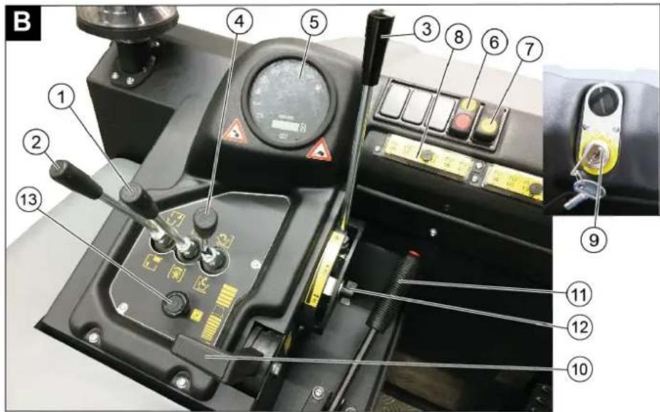


1 Páka prestavenia sedadla
2 Sedadlo vodiča
→ Páku prestavenia sedadla vytiahnite smerom von.
→ Posuňte sedadlo, uvoľnite páku a ne-
chajte ju zapadnút na svoje miesto.
→ Pohybmi sedadla dopredu a dozadu skontrolujte, či je aretované.
natural_image
Diagram of a medical or surgical procedure showing a device with a circular component and tubing, no text or symbols present.→ Posadte sa na sedadlo vodiča.
→ Zaaretujte parkovaciu brzdu (11).
→ Nastavenie otáčok motora (10) 1/3 posuňte dopredu.
Naštartujte motor
natural_image
Close-up of a mechanical component with textured surface and numbered annotations (1, 2, 3), no readable text or symbols beyond labels.1 Ovládacia páka zametacieho valca a bočnej metly
2 Obslužná páka nádoby na smeti
3 Ovládacia páka zametacieho valca
4 Obslužná páka klapky nádoby
→ Zapnút dúchadlá.
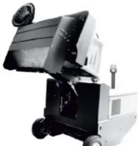
natural_image
Black and white photo of a small industrial machine with wheels and a fan (no visible text or symbols)natural_image
Close-up of a mechanical assembly with labeled parts (1 and 2), showing a red tool inserted into a component, connected to wires and a bracket (no readable text or symbols)1 P l u s o v ÿ p ó l
2 Zakrytie pólov
3 Mínusový pól
natural_image
Electrical testing setup with a battery pack and connected cable (no visible text or symbols)natural_image
Close-up of an internal combustion engine bay with hoses and components (no visible text or symbols)natural_image
Close-up of a mechanical assembly with labeled parts (1 and 2), no visible text or symbols beyond labels1 Vypúšťacia skrutka oleja
natural_image
Close-up of a dark vehicle's side panel with two numbered annotations pointing to the wheel (no visible text or symbols)1 K l ú č
2 Bočný plášť
natural_image
Interior view of a stainless steel enclosure with visible ductwork and wiring (no text or symbols)1 Upevňovací strmeň
2 Krídlová matica
3 Bočné tesnenie
natural_image
Diagram of a layered structure with a blue upward arrow at the bottom (no text or symbols)→ Skontrolujte tlak v pneumatikách.
→ Vypnie nasávací ventilátor.
So zametacím strojom prejdite po rovnej, hladkej podlahe, ktorá je viditel'ne znečistená prachom alebo posypaná kriedou.
→ Ovládacia páka zametacieho valca a bočnej metly (1) dozadu: Zapnutie zametacieho valca.
Ovládacia páka zametacieho valca (3) dozadu: Zametací valec sa spustí.
→ Zametací valec nechajte bežat' cca 10 sekúnd.
→ Ovládacia páka zametacieho valca a bočnej metly (1) do stredu.
Ovládacia páka zametacieho valca (3) dopredu: Zametací valec sa zdvihne.
→ Prejdite strojom smerom dozadu.
→ Skontrolujte pozametanú plochu.
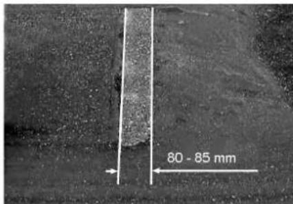
1 Uzáver krytu zariadenia
2 Kryt prístroja
3 Kryt filtra
1 Uzáver, kryt filtra (2x)
2 Kryt filtra
→ Otvorte uzáver.
→ Otvorte kryt filtra.
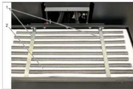
natural_image
Close-up of a metallic rack with two labeled components (1 and 2), no visible text or symbols on the rack itself.1 Priečka
2 Prachový filter
natural_image
Technical line drawing of a mechanical assembly with gears and shafts (no text or symbols)1 Krídlová matica
2 Odlučovač odstredivej sily
→ Odskrutkujte krídlovú maticu na odlučovači odstredivej sily.
→ Vyčistite odlučovač odstredivej sily.
Výmena poistiek

1 Drážkovaná matica
2 Kryt bezpečnostnej skrinky
→ Vyskrutkujte matice s drážkou.
→ Otvorte kryt na bezpečnostnej skrini.
→ Skontrolovat' poistky.
→ Chybné poistky vymeňte.
natural_image
Interior view of a vehicle engine bay with visible wiring, sensors, and control panel (no text or symbols)1 Poistka FU 1 (hlavná poistka)
| FU 01* Hlavná poistka 60 A | |
| FU 02 KlaksónNasávací ventilátor | 20 A |
| FU 03 Multifunkčný indikátor 3 A | |
| FU 04 Výstražný maják 5 A | |
| FU 05 Kontrolná jednotka motora | 10 A |
| FU 06 Kabína vodiča (volitel-né)Stierače | 10 A |
| FU 07 Indikátor stavu naplnenia LPG | 5 A |
| FU 08 Spúšťač 10 A | |
| FU 09 Osvetlenie vlavo 7,5 A | |
| FU 10 Osvetlenie vpravo 7,5 A | |
| FU 11 Pracovné osvetlenie 10 A | |
| FU 12 Vibračný systém 25 A | |
| FU 13 Ventil LPGSignál na jazdu spät' | 7,5 A |
2006/42/ES (+2009/127/ES)
2014/30/EÚ
2000/14/ES
Uplatňované harmonizované normy:
EN 60335-1
EN 60335-2-72
EN 55012: 2007 + A1: 2009
EN 61000-6-2: 2005
EN 62233: 2008
Chairman of the Board of Management

S. Reiser Director Regulatory Affairs & Certification
71364 Winnenden (Germany)
Tel.: +49 7195 14-0
Fax: +49 7195 14-2212
Winnenden, 2020/01/01
www.kaercher.com/REACH
Jamstvo
1 Vijak
2 Ključ
→ Odvijte vijak.
→ Skinite ključ.
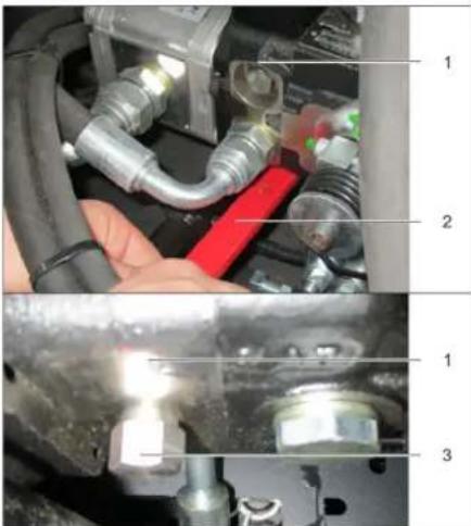
1 Hidraulička pumpa
2 Ključ
3 M a t i c a
→ Ključem otpuštajte maticu (otvorite slobodni hod) sve dok se uređaj ne može gurati.
→ VAŽNO: Maticu nakon guranja ponovno zatvorite (zatvorite slobodni hod = položaj za vožnju).
Stavljanje u pogon
Opće napomene
→ Prije stavljanja u pogon pročitajte i obratite pažnju na upute za rad koje izdaje proizvođač motora, a prvenstveno na sigurnosne naputke.
→ Stroj za metenje postavite na ravnu podlogu.
→ Izvucite kontaktni ključ.
→ Zakočite pozicijsku kočnicu.
1 Plinska boca
2 Sigurnosna šipka
3 Žičani zatvarač
→ Otpustite vijak na sigurnosnoj poluzi i zakrenite polugu.
→ Zamijenite plinsku bocu.
→ Odvijte zaštitnu kapicu s priključnog ventila plinske boce.
→ Zatvorite žičani zatvarač.
1 Poluga za namještanje sjedala
2 Sjedalo vozača
natural_image
Diagram of a mechanical device with rotating arm and pipe connection (no text or symbols)→ Sjedite na sjedalo.
→ Aretirajte pozicijsku (ručnu) kočnicu (11).
→ Podešavač broja okretaja motora (10) 1/3 gurnite prema naprijed.
Pokretanje motora
→ Za pokretanje motora treba pritisnuti kočnu papučicu.
→ Kod hladnih vanjskih temperatura: Povucite čok (13).
→ Kontaktni ključ okrenite udesno i pokrenite uređaj.
→ Kada je stroj pokrenut pustite kontaktni ključ.
→ Ako motor radi, pritisnite čok.
1 Papučica kočnice
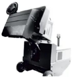
natural_image
Black-and-white photo of a small industrial machine with wheels and a handle (no visible text or symbols)→ Podignite valjak za metenje i bočnu metlu upravljačkim polugama: Upravljačka poluga 1 u sredinu i upravljačka poluga 3 prema naprijed.
→ Zatvorite poklopac spremnika pomicanjem upravljačke poluge (4) unatrag.
→ Podignite spremnik nakupljene prljavštine pomicanjem upravljačke poluge (2) unatrag.
→ Polako dovezite uređaj do sabirne posude.
→ Zakočite pozicijsku kočnicu.
→ Otvorite poklopac spremnika tako što ćete upravljačku polugu (4) pritisnuti unaprijed i ispraznite spremnik nakupljene prljavštine.
→ Zatvorite poklopac spremnika tako što ćete upravljačku polugu (4) povući unatrag tako da se zakrene u krajnji položaj.
→ Otpustite pozicijsku kočnicu.
→ Polako udaljite uređaj od sabirne posu-
de.
→ Spustite spremnik nakupljene prljavštine u krajnji položaj pomicanjem upravljačke poluge (2) unaprijed.
natural_image
Close-up of a mechanical assembly with red lever and wiring (no visible text or symbols)1 Držač sigurnosne šipke
2 Sigurnosna šipka
→ Sigurnosnu šipku za visoko pražnjenje preklopite prema gore i utaknite u držač (time ste je fiksirali).
| Tekućine poput motornog ulja, hidrauličkog ulja, kočione tekućine, dizela ili rashladnog sredstva ne smiju dospjeti u tlo. Štitite okoliš i zbrinite tekućine na ekološki svjestan način. |
Sigurnosni napuci za rad akumulatora
natural_image
Electrical testing setup with a rectangular device connected to a grid-based display unit (no visible text or symbols)→ Odvijte zatvarače svih ćelija.
(samo kod akumulatora koji se lako održavaju)
→ Plus pol punjača povežite s plus polom akumulatora.
→ Minus pol punjača povežite s minus polom akumulatora.
→ Utaknite strujni utikač u utičnicu i uključite punjač.
→ Napunite akumulator s najslabijom mogućom strujom punjenja.
→ Kada je akumulator napunjen, punjač najprije odvojite od električne mreže pa zatim od akumulatora.
→ Zavijte zatvarače ćelija.
(samo kod akumulatora koji se lako održavaju)
Vađenje akumulatora
→ Odvojite stezaljku s minus pola (-).
→ Odvojite stezaljku s plus pola (+).
→ Otpustite držače na dnu akumulatora.
→ Skinite akumulator s držača.
→ Prazan akumulator zbrinite u otpad su- kladno zakonskim odredbama.
1 Držač sigurnosne šipke
2 Spremnik kočne tekućine
3 Poklopac
→ Podignite spremnik nakupljene prljavštine i osigurajte ga pomoću sigurnosne šipke; pogledajte poglavlje „Pražnjenje spremnika nakupljene prljavštine“
→ Provjerite ima li dovoljno kočne tekućine u spremniku.
Napomena
natural_image
Close-up of an internal combustion engine bay with hoses and components (no visible text or symbols)natural_image
Close-up of a mechanical assembly with labeled parts (1 and 2), no visible text or symbols beyond labels1 Vijak za ispuštanje ulja
2 Filtar motornog ulja
→ Odvijte vijak za ispuštanje ulja.
→ Odvijte poklopac za ulijevanje ulja.
→ Ispustite ulje.
→ Odvijte filtar za ulje.
→ Očistite prihvatnik i brtveće površine.
→ Prije ugradnje uljem premažite brtvu novog filtra za ulje.
→ Ugradite filtar za ulje i pritegnite ga rukom.
→ Uvijte vijak za ispuštanje ulja zajedno s novim brtvilom.
Zatezni moment: 25 Nm
→ Ulijte motorno ulje.
Za vrstu ulja i količinu punjenja pogledajte poglavlje "Tehnički podaci".
→ Zatvorite poklopac za ulijevanje ulja.
→ Ostavite motor neka radi približno 10 sekundi.
→ Provjerite razinu motornog ulja.
natural_image
Close-up of a car's side panel with visible tire and bolt holes, no text or symbols present1 Ključ
2 Bočna oplata
→ Podignite spremnik za prljavštinu i osigurajte ga sigurnosnom polugom.
→ Otvorite bočnu oplatu ključem.
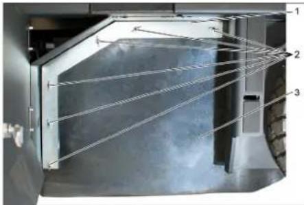
natural_image
Interior view of a laboratory or industrial facility with labeled components (1, 2, 3) and internal structure, showing no readable text or symbols.1 Pričvrsni luk
2 Leptir matica
3 Bočna brtva
→ Odvijte leptir matice.
→ Skinite pričvrsni luk.
→ Bočnu brtvu preklopite prema van.
→ Odvijte pričvrsni vijak prihvatnika valjka za metenje pa zakrenite prihvatnik prema van.
natural_image
Abstract geometric pattern with layered chevron shapes and a blue upward arrow (no text or symbols)natural_image
Close-up of a mechanical assembly with labeled parts (1 and 2), showing a red tool inserted into a black panel and connected cables (no text or symbols visible)1 Zaporni klizač poklopca uređaja
2 Poklopac uređaja
3 Poklopac filtra
natural_image
Technical diagram of a mechanical housing or enclosure with labeled components and an arrow indicating rotation (no text or symbols present)1 Zatvarač, poklopac filtra (2x)
2 Poklopac filtra
→ Otvorite zatvarač.
→ Otvorite poklopac filtra.
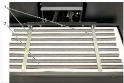
natural_image
Mechanical assembly with two labeled components and a metal grate (no visible text or symbols)1 Poprečni držač
2 Filtar za prašinu
→ Provjerite filtar za prašinu, po potrebi ga očistite ili zamijenite.
Napomena
Filtar za prašinu smije mijenjati samo servisna služba poduzeća Kärcher.
→ Postavite i pričvrstite poklopac filtra.
Provjera i namještanje klinastog remena
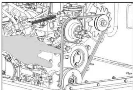
natural_image
Technical line drawing of a mechanical assembly with gears and linkages (no text or symbols)Klinasti remen mora se pri pritisku od 10 kg utisnuti približno 7-9 mm.
→ Namještanje zategnutosti klinastog remenja prepustite ovlaštenoj servisnoj službi.
1 Leptir matica
2 Centrifugalni separator
→ Odvijte leptir maticu na centrifugalnom separatoru.
→ Očistite centrifugalni separator.
Zamjena osigurača

1 Matice s nazubljenom glavom
2 Poklopac kutije s osiguračima
natural_image
Interior view of a vehicle engine bay with visible wiring, valves, and control panel (no text or symbols)1 Osigurač FU 1 (glavni osigurač)
2006/42/EZ (+2009/127/EZ)
2014/30/EU
2000/14/EZ
Primijenjene uskladene norme:
EN 60335-1
EN 60335-2-72
EN 55012: 2007 + A1: 2009
EN 61000-6-2: 2005
EN 62233: 2008
H. Jenner Chairman of the Board of Management

S. Reiser Director Regulatory Affairs & Certification
71364 Winnenden (Germany)
Tel.: +49 7195 14-0
Fax: +49 7195 14-2212
Winnenden, 2020/01/01
Opšte napomene. . . . . . . . . SR 1
www.kaercher.com/REACH
Garancija
U svakoj zemlji važe garantni uslovi koje je izdala naša nadležna distributivna organizacija. Eventualne smetnje na uređaju za vreme trajanja garancije uklanjamo besplatno, ukoliko je uzrok greška u materijalu ili proizvodnji. U slučaju koji podleže garanciji obratite se sa potvrdom o kupovini Vašem prodavcu ili najbližoj ovlašćenoj servisnoj službi.
Pribor i rezervni delovi
△OPASNOST
U cilju sprečavanja opasnosti, popravke i ugradnju rezervnih delova sme izvoditi samo ovlašćena servisna služba.
1 Z a v r t a n j
2 Ključ
→ Odvijte zavrtanj.
→ Izvaditi ključ.

1 Hidraulička pumpa
2 Ključ
3 Navrtka
1 Boca za gas
2 Sigurnosna poluga
3 Žičani zatvarač
→ Otpustiti zavrtanj na sigurnosnoj poluzi i zakrenuti polugu.
→ Zamenite bocu za gas.
→ Odvijte zaštitnu kapicu s priključnog ventila boce sa gasom.
→ Zatvorite žičani zatvarač.
natural_image
Diagram of a mechanical device with rotating arm and tubing, no text or symbols present→ Otvorite ventil za ispuštanje gasa okretanjem ulevo.
Pokretanje uređaja
Napomena: Ovaj uređaj poseduje kontaktni prekidač sedišta vozača. Uređaj se isključuje čim vozač ustane sa sedišta.
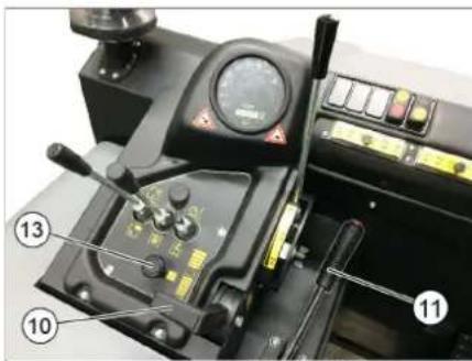
→ Sedite na sedište.
→ Blokirati ručnu kočnicu (11).
→ Podešavanje broja obrtaja motora (10) 1/3 gurnuti prema napred.
Pokretanje motora
→ Za pokretanje motora treba pritisnuti kočnu pedalu.
→ Na niskim spoljašnjim temperaturama: povući prigušnicu (13).
→ Ključ za paljenje okrenuti u desnu stranu i pokrenuti uređaj.
→ Kada je uređaj pokrenut, pustite kontaktni ključ.
→ Ako motor pravilno radi, prigušnicu pritisnuti.
Napomena: Pokretač se nikada ne sme držati uključen duže od 10 sekundi. Pre ponovnog uključivanja pokretača treba sačekati najmanje 10 sekundi.
Vožnja uređaja
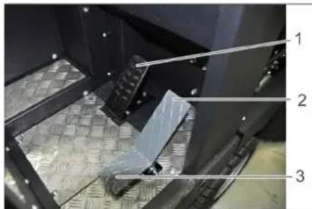
1 Kočna pedala
1 Poluga za rukovanje valjkom za metenje i bočnom metlom
2 Upravljačka poluga posude za nakupljenu prljavštinu
3 Poluga za rukovanje valjkom za metenje
4 Upravljačka poluga poklopca posude
Poluga za rukovanje valjkom za metenje i bočnom metlom
→ Uključite ventilatore.
→ Prilikom površinskog čišćenja: Poluga za rukovanje valjkom za metenje i bočnom metlom (1) prema nazad: valjak za metenje uključen. Poluga za rukovanje valjkom za metenje (3) prema nazad: valjak za metenje se spušta.
→ Upravljačka poluga poklopca posude (4) unapred: Poklopac posude se otvara.
Prilikom čišćenja bočnih ivica: Poluga za rukovanje valjkom za metenje i bočnom metlom (1) prema napred: valjak za metenje uključen, bočna metla uključena i spušta se. Poluga za rukovanje valjkom za metenje (3) prema nazad: valjak za metenje se spušta.

natural_image
Industrial robotic device with wheels and a mounted panel (no visible text or symbols)→ Podignuti valjak za metenje i bočnu metlu pomoću poluga za rukovanje: Poluga za rukovanje 1 na sredinu, a poluga za rukovanje 3 prema napred.
→ Da zatvorite poklopac posude upravljačku polugu (4) pomerite unazad.
→ Da podignete posudu za nakupljenu prljavštinu upravljačku polugu (2) pomerite unazad.
→ Polako navezite uređaj do sabirne posude.
→ Zakočite pozicionu kočnicu.
→ Otvorite poklopac posude tako što ćete upravljačku polugu (4) pritisnuti unapred i isprazniti posudu za nakupljenu prljavštinu.
→ Da zatvorite poklopac posude upravljačku polugu (4) povucite unazad tako da se zakrene u krajnji položaj.
→ Otkočite pozicionu kočnicu.
→ Polako udaljite uređaj od sabirne posude.
→ Spustite posudu za nakupljenu prljavštinu u krajnji položaj tako što ćete upravljačku polugu (2) pomeriti unapred.
natural_image
Close-up of a mechanical assembly with red robotic arm and wiring (no visible text or symbols)1 Držač sigurnosne poluge
2 Sigurnosna poluga
→ Sigurnosnu polugu za visoko pražnjenje preklopite prema gore i utaknite u držač (time ste je fiksirali).
| Tečnosti kao što su motorno ulje, hidrauličko ulje, kočiona tečnost, dizel ili rashladno sredstvo ne smeju da dospeju u zemljište. Čuvajte životnu sredinu i tečnosti odložite u otpad u skladu sa ekološkim pravilima. |
Sigurnosne napomene za rad akumulatora
Pri radu sa akumulatorima obavezno obratite pažnju na sledeća upozorenja:
| Uzmite u obzir instrukcije na akumulatoru, u uputstvu za upotrebu i u uputstvu za rad vozila! | |
| Nosite zaštitne naočare! | |
| Kiseline i akumulatore držite van domašaja dece! | |
| Opasnost od eksplozije! | |
| Zabranjeni su vatra, varničenje, otvoren plamen i pušenje! | |
| Opasnost od povreda kiselinom! | |
| Prva pomoć! | |
| Upozorenje! | |
| Odlaganje u otpad! | |
| Akumulator se ne sme baciti u kantu za smeće! |
△OPASNOST
Opasnost od eksplozije!
→ Koristite samo akumulatore sa kapicama. U slučaju da je izgubite, nabavite novu kapicu.
△OPASNOST
Opasnost od eksplozije!
→ Ne stavljajte na akumulator nikakav alat niti slične predmete. Opasnost od kratkog spoja i eksplozije.
△OPASNOST
Opasnost od povreda!
→ Rane nikad ne dovodite u kontakt sa olovom. Nakon radova sa akumulatorom uvek operite ruke.
△OPASNOST
Opasnost od požara i eksplozije!
→ Zabranjeni su pušenje i otvoren plamen.
→ Prostorije u kojima se pune akumulatori moraju biti dobro provetrene, jer se pri punjenju stvara visoko eksplozivan gas.
△OPASNOST
Opasnost od povreda kiselinom!
→ Ako kiselina prsne u oči ili na kožu, odmah isperite sa puno čiste vode.
→ Nakon toga se bez odlaganja obratite lekaru.
→ Kontaminiranu odeću operite u vodi.
1 Plus pol
2 Kapica za pol akumulatora
3 M i n u s p o l
→ Akumulator postavite u držač akumulatora.
→ Zavrtnjima pričvrstite držače na dnu akumulatora.
→ Stezaljku (crveni kabl) priključite na plus pol (+).
→ Drugu stezaljku priključite na minus pol (-).
→ Postavite kapicu na pol akumulatora.
→ Proverite da li su polovi i stezaljke akumulatora dovoljno zaštićeni mazivom.
Provera nivoa i dopunjavanje akumulatorske kiseline (samo kod akumulatora lakih za održavanje sa zatvaračima ćelija)
OPREZ
Opasnost od oštećenja!
→ Kod akumulatora punjenih kiselinom redovno proveravajte nivo tečnosti.
→ Odvijte zatvarače svih ćelija.
→ Iz svake ćelije uzmite uzorak uređajem za merenje kiseline.
– Specifična težina kiseline potpuno napunjenog akumulatora na 20°C iznosi 1,28 kg/l.
– Kod delimično ispražnjenog akumulatora specifična težina kiseline iznosi između 1,00 i 1,28 kg/l.
– Specifična težina kiseline mora biti ista u svim ćelijama.
→ Uzorak kiseline vratite nazad u istu ćeliju.
→ Ako je nivo tečnosti premali, dopunite ćelije destilisanom vodom do oznake.
→ Napunite akumulator.
→ Zavijte zatvarače ćelija.
Punjenje akumulatora
△OPASNOST
Opasnost od povreda!
natural_image
Electrical testing device with connected cables and a control panel (no visible text or symbols)→ Odvijte zatvarače svih ćelija.
(samo kod akumulatora koji se lako održavaju)
→ Plus pol punjača povežite sa plus polom akumulatora.
→ Minus pol punjača povežite sa minus polom akumulatora.
→ Utaknite strujni utikač u utičnicu i uključite punjač.
→ Napunite akumulator sa najslabijom mogućom strujom punjenja.
→ Kada je akumulator napunjen, punjač najpre odvojite od električne mreže pa zatim od akumulatora.
→ Zavijte zatvarače ćelija.
(samo kod akumulatora koji se lako održavaju)
Vađenje akumulatora
→ Odvojite stezaljku sa minus pola (-).
→ Odvojite stezaljku sa plus pola (+).
→ Otpustite držače na dnu akumulatora.
→ Skinite akumulator s držača.
→ Prazan akumulator odložite u otpad u skladu sa važećim odredbama.
Provera nivoa kočne tečnosti i dopuna ⚠ OPASNOST
Opasnost od povreda!
→ Uvek postavite sigurnosnu polugu kada je posuda za nakupljenu prljavštinu podignuta.
→ Osiguranje izvedite samo izvan oblasti opasnosti.
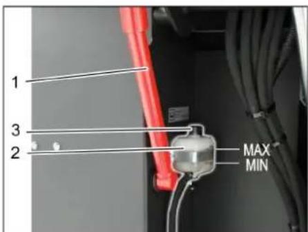
natural_image
Close-up of an automotive engine bay with hoses and components (no visible text or symbols)1 Poklopac za dolivanje ulja (motor)
2 Šipka za merenje nivoa ulja
→ Izvucite šipku napolje.
→ Obrišite i ugurajte štap unutra.
→ Izvucite šipku napolje.
→ Očitajte nivo ulja.
→ Šipku za merenje ulja ponovo ugurajte unutra.
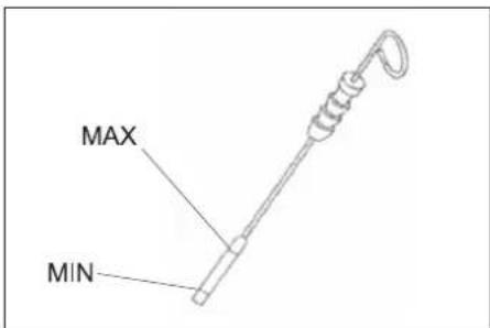
– Nivo ulja mora da se nalazi između oznaka "MIN" i "MAX".
- Ako je nivo opao ispod oznake "MIN", motorno ulje treba dopuniti.
– Nemojte puniti motor preko oznake "MAX".
→ Odvijte poklopac za dolivanje ulja.
→ Ulijte motorno ulje.
Za vrstu ulja pogledajte poglavlje
"Tehnički podaci".
→ Zatvorite poklopac za dolivanje ulja.
→ Sačekajte najmanje 5 minuta.
→ Proverite nivo motornog ulja.
Zamena motornog ulja i filtera za motorno ulje
OPREZ
Opasnost od opekotina vrelim motornim uljem!
→ Ostavite motor da se ohladi.
→ Pripremite prihvatnu posudu za najmanje 6 l motornog ulja.
→ Ostavite motor da se ohladi.
natural_image
Close-up of a mechanical engine component with labeled parts (1 and 2), showing internal gears and hoses without any readable text or symbols.1 Ispusni zavrtanj ulja
2 Filter motornog ulja
→ Odvijte zavrtanj za ispuštanje ulja.
→ Odvijte poklopac za dolivanje ulja.
→ Ispustite ulje.
→ Odvijte filter za ulje.
→ Očistite prihvatnik i zaptivne površine.
→ Pre ugradnje premažite uljem zaptivku novog filtera za ulje.
→ Ugradite filter za ulje i pritegnite ga rukom.
→ Zavijte zavrtanj za ispuštanje ulja zajedno sa novom zaptivkom.
Zatezni moment: 25 Nm
→ Ulijte motorno ulje.
Za vrstu ulja i količinu punjenja pogledajte poglavlje "Tehnički podaci".
→ Zatvorite poklopac za dolivanje ulja.
→ Ostavite motor da radi približno 10 sekundi.
→ Proverite nivo motornog ulja.
Provera i dolivanje hidrauličkog ulja SAVET
Posuda za prijavštinu ne sme da bude podignuta.
→ Otvorite poklopac motora i poduprite ga potpornikom.
1 Ekspanziona posuda za rashladno sredstvo
→ Proverite nivo napunjenosti kada je motor hladan.
→ Proverite nivo napunjenosti ekspanzione posude za rashladno sredstvo.
Pravi nivo rashladnog sredstva je kada je između oznaka MIN i MAX.
natural_image
Close-up of a dark vehicle's side panel with bolt holes and a tire, no visible text or symbols1 Ključ
2 Bočna oplata
→ Podignite posudu za nakupljenu prljavštinu i poduprite je sigurnosnom polugom.
→ Ključem otvorite bočnu oplatu.
natural_image
Interior view of a mechanical or industrial facility with numbered components (1, 2, 3) and connecting lines, no visible text or symbols.1 Kuka za držanje
2 Leptir navrtka
3 Bočna zaptivka
natural_image
Abstract geometric pattern with layered triangular shapes and a blue upward arrow (no text or symbols)Položaj ugradnje valjka za metenje u smeru vožnje (pogled odozgo)
Napomena: Pri ugradnji novog valjka za metenje pazite na položaj garniture čekinja.
→ Ugradite novi valjak za metenje. Žlebovi valjaka za metenje moraju biti nataknuti na ispuste naspramnih držača.
Napomena: Nakon ugradnje novog valjka za metenje mora se iznova podesiti profil metenja.
Provera i podešavanje profila metenja valjka za metenje
Napomena: Profil metenja je fabrički podešen na 80 mm, a u slučaju istrošenosti valjka za metenje se može kontinualno podesiti.
→ Proverite pritisak vazduha u gumama.
→ Isključite usisni ventilator.
→ Uređaj za metenje odvezite na ravnu i glatku površinu koja je vidljivo prekrivena prašinom ili izmrvljenom kredom.
→ Poluga za rukovanje valjkom za metenje i bočnom metlom (1) prema nazad: valjak za metenje uključen. Poluga za rukovanje valjkom za metenje (3) prema nazad: valjak za metenje se spušta.
→ Valjak za metenje ostaviti da radi na oko 10 sekundi.
→ Poluga za rukovanje valjkom za metenje i bočnom metlom (1) na sredini.
Poluga za rukovanje valjkom za metenje (3) prema napred: valjak za metenje se podiže.
→ Pomerite uređaj vozeći ga unazad.
→ Proverite profil metenja.
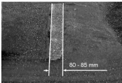
Pometena površina treba da ima oblik pravilnog pravougaonika širine između 80 i 85 mm.
→ Otvoriti i podesiti granični zavrtanj naknadnog podešavanja habanja (12). Graničnik prema gore: uži profil metenja.
Graničnik prema dole: širi profil metenja.
→ Ponovo čvrsto pritegnuti granični zavrtanj.
→ Ponovo proveriti profil metenja valjka za metenje kao što je već opisano.
Provera i podešavanje profila metenja bočne metle
→ Podignite bočnu metlu.
→ Uređaj za metenje odvezite na ravnu i glatku površinu koja je vidljivo prekrivena prašinom ili izmrvljenom kredom.
→ Bočnu metlu sa polugom za rukovanje spustiti i ostaviti da radi oko 10 sekundi.
→ Podignite bočnu metlu.
→ Pomerite uređaj vozeći ga unazad.
→ Proverite profil metenja.
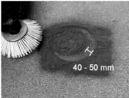
natural_image
Close-up of a mechanical assembly with red clamping tool and wiring (no visible text or symbols)1 Držač sigurnosne poluge
2 Sigurnosna poluga
→ Bočnu oplatu otvorite kao što je opisano u poglavlju "Zamena valjka za metenje".
→ Otpustite 6 kom. leptir navrtki na bočnom limenom držaču.
→ Otpustite 3 kom. navrtki (širine ključa 13) na prednjem limenom držaču.
→ Bočnu zaptivku pritisnite na dole (uzdužna rupa) tako da bude udaljena 1 - 3 mm od poda.
→ Zavijte limene držače.
→ Ponovite postupak na drugoj strani uređaja.
Ručno čišćenje filtera za prašinu

1 Blokada poklopca uređaja
2 Poklopac uređaja
3 Poklopac filtera
natural_image
Technical line drawing of a mechanical housing component with labeled parts (1 and 2), showing internal components and an arrow indicating rotation or movement (no text or symbols beyond labels)1 Zatvarač, poklopac filtera (2x)
2 Poklopac filtera
→ Otvorite zatvarač.
→ Otvorite poklopac filtera.

natural_image
Mechanical assembly with two labeled components and a metal grate (no visible text or symbols)1 Poprečni držač
2 Filter za prašinu
→ Proverite filter za prašinu, po potrebi ga očistite ili zamenite.
Napomena
Filter za prašinu sme da menja samo servisna služba kompanije Kärcher.
→ Postavite i pričvrstite poklopac filtera.
Proverite i podesite klinasti remen

natural_image
Technical line drawing of a mechanical assembly with gears and linkages (no text or symbols)Klinasti remen se mora pri pritisku od 10 kg utisnuti približno 7-9 mm.
→ Podešavanje zategnutosti klinastog remenja prepustite ovlašćenoj servisnoj službi.
Provera i zamena filtera za vazduh

1 Z a t v a r a č
1 Leptir navrtka
2 Centrifugalni separator
→ Odvijte leptir navrtku na centrifugalnom separatoru.
→ Očistite centrifugalni separator.
Zamena osigurača

natural_image
Interior view of a vehicle engine bay with visible wiring, valves, and control panel (no text or symbols)1 Osigurač FU 1 (glavni osigurač)
| FU 01* Glavni osigurač 60 A | |
| FU 02 SirenaUsisni ventilator | 20 A |
| FU 03 Višenamenski ekran 3 A | |
| FU 04 Rotirajuće svetlo 5 A | |
| FU 05 Kontrolna jedinica motora | 10 A |
| FU 06 Upravljačka kabina (opcija)Brisač stakla | 10 A |
| FU 07 LPG pokazivač napunjenosti | 5 A |
| FU 08 Pokretač 10 A | |
| FU 09 Svetlo s leve strane 7,5 A | |
| FU 10 Svetlo s desne strane 7,5 A | |
| FU 11 Radno svetlo 10 A | |
| FU 12 Vibracioni sistem 25 A | |
| FU 13 LPG ventilSignalizacija vožnje unazad | 7,5 A |
* Ove osigurače sme da se zameni isključivo servisna služba, jer je neophodna provera uređaja na postojanje svih mogućih eventualnih greški.
Otklanjanje smetnji
| Smetnja Otklanjanje | |
| Uređaj se ne može pokrenuti | Sedite na sedište vozača, kontaktni prekidača sedišta vozača se aktivira. |
| Za pokretanje motora treba pritisnuti kočnu pedalu. | |
| Punjenje ili zamena akumulatora | |
| Prazna boca za gas - zamenite je. | |
| Zatvoren ventil za ispuštanje gasa - otvorite ga okretanjem ulevo. | |
| Ventil za gas je zaleđen - pogledajte opis zamene boce za gas. | |
| Obavestite Kärcher servisnu službu. | |
| Motor radi neravnomerno | Očistite filter za vazduh ili zamenite filterski uložak. |
| Proverite i po potrebi popravite sistem vodova za gorivo, priključke i spojeve. | |
| Proveriti položaj ugradnje gasne boce: priključak odn. prstenasti otvor mora da pokazuje prema dole. | |
| Obavestite Kärcher servisnu službu. | |
| Pregrejan motor Dopunite rashladno sredstvo | |
| Motor radi, ali se uređaj kreće sporo ili nikako | Otkočite pozicionu kočnicu |
| Zatvorite slobodan hod (položaj za vožnju) | |
| Papučicu za gas postavite sasvim prema napred (visok broj obrtaja). | |
| Proverite da nema upletenih traka ili petlji. | |
| Obavestite Kärcher servisnu službu. | |
| Pišteći zvuk u hidraulici Sipajte hidrauličku tečnost | |
| Četke se vrte polako ili se uopšte ne vrte | Papučicu za gas postavite sasvim prema napred (visok broj obrtaja). |
| Proverite da nema upletenih traka ili petlji. | |
| Obavestite Kärcher servisnu službu. | |
| U prostoru četki je usisna snaga mala ili je uopšte nema | Proverite, očistite ili zamenite filter za prašinu. |
| Obavestite Kärcher servisnu službu. | |
| Uređaj diže prašinu Podešavanje b | bčnih zaptivki |
| Uključite ventilator. | |
| Proverite, očistite ili zamenite filter za prašinu. | |
| Zamenite filterske zaptivke | |
| Otvorite poklopac posude za nakupljenu prljavštinu. | |
| Obavestite Kärcher servisnu službu. | |
| Jedinica za čišćenje ostavlja prljavštinu da leži | Ispraznite posudu za nakupljenu prljavštinu |
| Proverite, očistite ili zamenite filter za prašinu. | |
| Zamenite valjak za metenje. | |
| Naknadno podesite profil metenja | |
| Zamenite zaptivne trake na posudi za prljavštinu | |
| Uklonite strana tela koja blokiraju valjak za metenje | |
| Otvorite poklopac posude za nakupljenu prljavštinu. | |
| Obavestite Kärcher servisnu službu. | |
| Posuda za prljavštinu ne može da se podigne ili spusti | Papučicu za gas postavite sasvim prema napred (visok broj obrtaja). |
| Ukloniti saigurnosni podupirač sa posude za nakupljenu prljavštinu | |
| Obavestite Kärcher servisnu službu. | |
| Poklopac posude za nakupljenu prljavštinu se ne otvara. | Obavestite Kärcher servisnu službu. |
| Smetnje u radu s hidrauličkim pokretnim delovima | Obavestite Kärcher servisnu službu. |
Tehnički podaci
| KM 120/250 R LPG Classic | ||
| Podaci uređaja | ||
| Brzina vožnje prema napred km/h 9 | ||
| Brzina vožnje unazad km/h 4 | ||
| Savladavanje uspona (maks.) % 18 | ||
| Površinski učinak bez bočnih metli m | ^2 /h 8100 | |
| Površinski učinak s bočnom metlom m | ^2 /h 10800 | |
| Radna širina bez bočne metle mm 900 | ||
| Radna širina sa bočnom metlom mm 1200 | ||
| Stepen zaštite, zaštićeno od kapajuće vode -- IPX 3 | ||
| Trajanje primene sa potpuno napunjenom gasnom bocom h | 4 | |
| Motor | ||
| Tip | -- | Kubota WG 972 GL-E3 |
| Tip | -- | 3-cilindarski LPG gasni motor sa 3-krakim katalizatorom |
| CO ^2 Emisija u skladu sa postupkom merenja EU odredbe 2016/1628 (stepen V) | g/kWh | 844,3 |
| Način hlađenja | -- | Hlađenje vodom |
| Smer obrtanja | -- | Suprotno smeru kazaljke sata |
| Otvor | mm 68 | |
| Hod | mm 68 | |
| Radna zapremina | cm ^3 | 740 |
| Količina ulja | I | 3,25 |
| Broj obrtaja pri radu | 1/min 2500 | |
| Maksimalan broj obrtaja | 1/min | 2500 |
| Broj obrtaja u praznom hodu | 1/min | 1300 |
| Maks. snaga | kW/PS | 12,7 / 17,0 |
| Najviši obrtni momenat pri 2400 1/min | Nm | 60 |
| Filter za ulje | -- | Filterski uložak |
| Filter za usisni vazduh | -- | Unutrašnji/spoljašnji filterski uložak |
| Vrsta goriva | LPGDozvoljene su smeše tečnog gasa od propana i butana.Udeo propana mora biti najmanje 90%. | |
| Zapremina rezervoara | 11 kg odn. 20 litara (rezervna boca) | |
| Električne komponente | ||
| Akumulator | V, Ah | 12, 52 |
| Generator trofazne struje | V, Watt | 12, 150 |
| Pokretač | -- | Elektrostarter |
| Hidrauličke komponente | ||
| Količina ulja u kompletnom hidrauličkom sklopu | I | 26,5 |
| Količina ulja u hidrauličkom rezervoaru | I | 21,2 |
| Vrste ulja | ||
| Motor (preko 25 °C) | -- | SAE 30, SAE 10W-30, SAE 15W-40 |
| Motor (0 do 25 °C) | -- | SAE 20, SAE 10W-30, SAE 10W-40 |
| Motor (ispod 0 °C) | -- | SAE 10W, SAE 10W-30, SAE 10W-40 |
| Hidraulika | -- | HV 46 |
| Posuda za nakupljenu prljavštinu | ||
| Maksimalna visina pražnjenja | mm 1400 | |
| Zapremina posude za prljavštinu | I | 250 |
| Valjak za metenje | ||
| Prečnik valjka za metenje | mm 300 | |
| Širina valjka za metenje | mm 900 | |
| Broj obrtaja | 1/min | 350 |
| Profil metenja | mm | 80 |
| Bočna metla | ||
| Prečnik bočnih metli | mm 600 | |
| Broj obrtaja (kontinualno) | 1/min | 0 - 60 |
| Pneumatici od pune gume | ||
| Veličina napred -- 15-4.5x8 | ||
| Veličina pozadi -- 15-4.5x8 | ||
| Kočnica | ||
| Prednji točkovi -- mehanička | ||
| Zadnji točak -- hidrostatička | ||
| Filterski i usisni sistem | ||
| Tip -- Vrećasti filter | ||
| Broj obrtaja 1/min 2800 | ||
| Površina filtera za finu prašinu m | ^2 | 6,0 |
| Nominalni podpritisak usisnog sistema | mbar | 15,5 |
| Nominalni zapreminski protok usisnog sistema | m^3/h | 800 |
| Vibracioni sistem | -- | Elektromotor |
| Okolni uslovi | ||
| Temperatura | °C | -5 do +40 |
| Vlažnost vazduha, bez stvaranja kondenzata | % | 0 - 90 |
| Izračunate vrednosti prema EN 60335-2-72 | ||
| Emisija buke | ||
| Nivo zvučnog pritiska L_pA | dB(A) | 83 |
| Nepouzdanost K_pA | dB(A) | 3 |
| Nivo zvučne snage L_WA + nepouzdanost K_WA | dB(A) | 104 |
| Vibracije uređaja | ||
| Vrednost vibracije na ruci | m/s^2 | <2,5 |
| Sedište | m/s^2 | 0,8 |
| Nepouzdanost K | m/s^2 | 0,1 |
| Dimenzije i težine | ||
| Dužina x širina x visina | mm | 2082x1250x1450 |
| Poluprečnik okretanja udesno | mm | 1350 |
| Poluprečnik okretanja ulevo | mm | 1350 |
| Prazna težina | kg | 851 |
| Dozvoljena ukupna težina | kg | 1300 |
| Dozvoljeno opterećenje prednje osovine | kg | 787 |
| Dozvoljeno opterećenje zadnje osovine | kg | 513 |
| Zadržavamo pravo na tehničke promene! | ||
Izjava o usklađenosti sa propisima EU
Ovim izjavljujemo da ovde opisana mašina po svojoj koncepciji i načinu izrade, sa svim njenim modelima koje smo izneli na tržište, odgovara osnovnim zahtevima dole navedenih propisa Evropske Zajednice o sigurnosti i zdravstvenoj zaštiti. Ova izjava prestaje da važi ako se bez naše saglasnosti na mašini izvedu bilo kakve promene.
Proizvod: Mašina za metenje sa usisavanjem samohodna Tip: KM 120/250 R LPG Classic 1.186-001.0
2006/42/EZ (+2009/127/EZ)
2014/30/EU
2000/14/EZ
Primenjene uskladene norme:
EN 60335-1
EN 60335-2-72
EN 55012: 2007 + A1: 2009
EN 61000-6-2: 2005
EN 62233: 2008

Chairman of the Board of Management
Director Regulatory Affairs & Certification
Opunomoćeni za izradu dokumentacije: S. Reiser
Alfred Kärcher SE & Co. KG
71364 Winnenden (Germany)
Tel.: +49 7195 14-0
Fax: +49 7195 14-2212
Winnenden, 2020/01/01
Общи указания.....BG 1
www.kaercher.com/REACH
Гаранция
1 Хидравлична помпа
1 Газова бутилка
2 Предпазна щанга
3 Затвор с хомут
natural_image
Diagram of a medical or laboratory procedure showing a device with tubing and a circular component, no text or symbols present.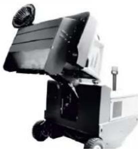
natural_image
Industrial robotic device with wheels and a mounted panel (no visible text or symbols)natural_image
Electrical testing setup with a battery pack and connected wiring (no visible text or symbols)natural_image
Close-up of an automotive engine bay with hoses and components (no visible text or symbols)natural_image
Close-up of a mechanical engine component with labeled parts (1 and 2), no visible text or symbols beyond labelsnatural_image
Close-up of a dark vehicle's side panel with bolted components and a tire, no visible text or symbols1 Ключ
natural_image
Interior view of a mechanical or industrial enclosure with visible structural lines and components (no text or symbols)natural_image
Abstract geometric pattern with diagonal stripes and a blue upward arrow (no text or symbols)natural_image
Close-up of a mechanical assembly with labeled parts (1 and 2), showing a red tool inserted into a blue component, connected to wires and a black base (no text or symbols visible)natural_image
Technical line drawing of a mechanical housing component with labeled parts (1 and 2), no readable text or symbols beyond labelsnatural_image
Close-up of a metallic rack with two labeled components (1 and 2), no visible text or symbols on the rack itself.natural_image
Technical line drawing of a mechanical assembly with gears and linkages (no text or symbols)1 Крилчата гайка
natural_image
Close-up of a control panel with multiple buttons and indicator lights (no readable text or symbols)


1 Гайка с назъбка
natural_image
Close-up of a car's front panel with two circular icons and a yellow warning triangle (no text or symbols visible)①
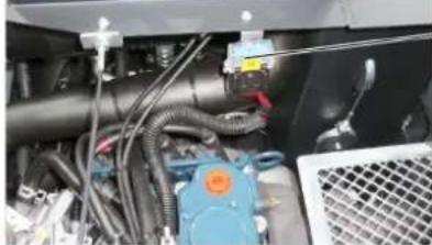
natural_image
Interior view of a vehicle engine bay with hoses, valves, and a blue fuel pump (no visible text or symbols)Chairman of the Board of Management

S. Reiser
Director Regulatory Affairs & Certification
71364 Winnenden (Germany)
Tel.: +49 7195 14-0
Fax: +49 7195 14-2212
Winnenden, 2020/01/01
Üldmärkusi.... ET 1
www.kaercher.com/REACH
Garantii


1 Hüdraulikapump
2 V ö t i
3 M u t t e r
Gaasiballooni paigaldamine/vahetamine
⚠️OHT
Vigastusoht!
Gaasiballooni paigaldamine
TÄHELEPANU
1 Gaasiballoon
2 Kinnituslatt
3 Klamberlukk
1 Istme reguleerimishoob
2 Juhiiste
natural_image
Diagram of a medical or laboratory procedure showing a device with tubing and a circular component, no text or symbols present.1 Piduripedaal
2 Gaasipedaal edasi
3 Gaasipedaal tagasi

natural_image
Black and white photo of a small industrial machine with wheels and a mounted panel (no visible text or symbols)natural_image
Close-up of a mechanical assembly with labeled parts (1 and 2), showing a red tool inserted into a black panel and cables (no text or symbols visible)natural_image
Electrical testing setup with a battery pack and connected wiring (no visible text or symbols)1 Kinnituslati hoidik
2 Pidurivedeliku mahuti
3 Lukustatav kaas
natural_image
Close-up of an automotive engine bay with hoses and components (no visible text or symbols)natural_image
Close-up of a mechanical engine component with labeled parts (1 and 2), no visible text or symbols beyond labelsnatural_image
Close-up of a dark metal vehicle's side panel with two labeled components (1 and 2), showing no visible text or symbols.1 V õ t i
2 Küljepaneel
natural_image
Interior view of a mechanical or industrial enclosure with visible structural lines and components (no text or symbols)natural_image
Abstract geometric pattern with layered gray and white shapes, featuring a blue upward arrow at the bottom (no text or symbols)1 Lukk, filtrikate (2x)
2 Filtrikate
→ Avage lukk.
→ Avage filtrikate.
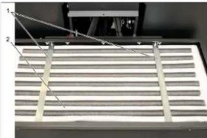
natural_image
Close-up of a metallic panel with two labeled components (1 and 2) and diagonal lines, no visible text or symbols.natural_image
Technical line drawing of a mechanical assembly with gears and levers (no text or symbols)1 Tiibmutter
natural_image
Interior view of a vehicle showing hoses, valves, and a control panel (no readable text or symbols)Toode: Imur-pühkija istmega
Tüüp: KM 120/250 R LPG Classic 1.186-001.0
Chairman of the Board of Management

S. Reiser
Director Regulatory Affairs & Certification
71364 Winnenden (Germany)
Tel.: +49 7195 14-0
Fax: +49 7195 14-2212
Winnenden, 2020/01/01
www.kaercher.com/REACH
Garantija
8 D ro š in ā t ā ji
1 Hidrauliskais süknis
2 Atslēga
3 Uzgrieznis
1 Gāzes balons
natural_image
Diagram of a medical or laboratory procedure showing a device with tubing and a circular component, no text or symbols present.natural_image
Close-up of a mechanical assembly with three numbered components (1, 2, 3) and no visible text or symbols.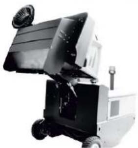
natural_image
Black and white photo of a small industrial machine with wheels and a fan (no visible text or symbols)natural_image
Close-up of a mechanical assembly with red tool and wiring (no visible text or symbols)natural_image
Electrical testing setup with a battery pack and connected circuit board (no visible text or symbols)natural_image
Close-up of an internal combustion engine bay with hoses and components (no visible text or symbols)natural_image
Close-up of a mechanical engine component with labeled parts (1 and 2), no visible text or symbols beyond labelsnatural_image
Close-up of a dark vehicle's side panel with two numbered components and a tire, no visible text or symbols1 Atslēga
2 Sānu apšuvums
natural_image
Interior view of a mechanical or industrial enclosure with visible structural lines and internal components (no text or symbols)natural_image
Diagram of a layered structure with a blue upward arrow, no text or symbols presentnatural_image
Close-up of a mechanical assembly with labeled parts (1 and 2), showing a red tool inserted into a blue panel and wiring (no text or symbols visible)natural_image
Technical line drawing of a mechanical component with labeled parts (1 and 2), showing internal structure and rotation arrow (no text or symbols beyond labels)1 Noslēgs, filtra pārsegs (2x)
2 Filtra pärsegs
→ Atveriet aizslēgu.
→ Atveriet filtra pärsegu.
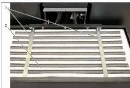
natural_image
Close-up of a metallic grate with two labeled components (1 and 2), no visible text or symbols on the grate itself.natural_image
Technical line drawing of a mechanical assembly with gears and springs (no text or symbols)Kīlsiksnai pie apm. 10 kg slodzes ir par 7-9 mm jāpadodas.
natural_image
Interior view of a mechanical or industrial device with visible pipes, valves, and a mesh grille (no readable text or symbols)
Chairman of the Board of Management

S. Reiser
Director Regulatory Affairs & Certification
71364 Winnenden (Germany)
Tel.: +49 7195 14-0
Fax: +49 7195 14-2212
Winnenden, 2020/01/01
Bendrieji nurodymai....LT 1
www.kaercher.com/REACH
Garantija
1 Hidraulinis siurblys
2 R a k t a s
3 Veržlé
1 Sédynés reguliavimo svirtis
2 Vairuotojo sédyné
natural_image
Diagram of a medical or laboratory procedure showing a device with tubing and a circular component, no text or symbols present.1 Stabdžio pedalas
→ ljunkite orpūte.
→ Valant plotus:

natural_image
Black and white photo of a small industrial machine with wheels and a handle (no visible text or symbols)natural_image
Electrical circuit setup with a battery pack connected to a power grid and cable (no visible text or symbols)natural_image
Close-up of an internal combustion engine bay with hoses and components (no visible text or symbols)1 Alyvos pripildymo dangtelis (variklis)
2 Alyvos matuoklé
natural_image
Close-up of a mechanical engine assembly with labeled parts (1 and 2), no visible text or symbols beyond labelsnatural_image
Close-up of a dark vehicle's side panel with two labeled components (1 and 2), showing no visible text or symbols.1 R a k t a s
2 Šoninė uždanga
natural_image
Interior view of a stainless steel enclosure with visible ductwork and ventilation system (no text or symbols)1 Kronšteinas
2 Sparnuotoji veržlé
3 Šoninis tarpiklis
→ Atsukite sparnuotasias veržles.
→ Nuimkite kronšteina.
→ Šoninj sandariklj paverskite j išorę.
natural_image
Abstract geometric pattern with layered triangular shapes and a blue upward arrow (no text or symbols)natural_image
Close-up of a mechanical assembly with red clamping device and wiring (no visible text or symbols)natural_image
Technical line drawing of a mechanical housing component with labeled parts (1 and 2), showing internal components and an arrow indicating rotation or movement (no text or symbols beyond labels)1 Filtro dangtelio fiksatorius (2x)
2 Filtro dangtelis
→ Atidarykite fiksatorius.
→ Atidarykite filtro dangtelj.
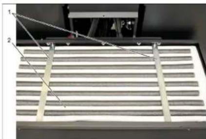
natural_image
Close-up of a metallic grate with two labeled components (1 and 2), no visible text or symbols on the grate itself.natural_image
Technical line drawing of a mechanical assembly with gears and springs (no text or symbols)natural_image
Interior view of an industrial machine with visible wiring, valves, and a mesh fan (no text or symbols)1 Saugiklis FU 1 (pagrindinis saugiklis)
71364 Winnenden (Germany)
Tel.: +49 7195 14-0
Fax: +49 7195 14-2212
Winnenden, 2020/01/01

1. Conner
Chairman of the Board of Management

S. Reiser
Director Regulatory Affairs & Certification
www.kaercher.com/REACH
Гарантія


natural_image
Diagram of a medical or laboratory procedure showing a device with tubing and a circular component, no text or symbols present.1 Педаль гальма

natural_image
Industrial robotic device with wheels and a mounted panel (no visible text or symbols)natural_image
Electrical testing setup with a control panel connected to an electronic device (no visible text or symbols)natural_image
Close-up of an automotive engine bay with hoses and components, no visible text or symbolsnatural_image
Close-up of a mechanical assembly with labeled parts (1 and 2), showing internal components and wiring (no readable text or symbols beyond labels)natural_image
Close-up of a dark vehicle's side panel with two labeled components (1 and 2), showing bolt holes and a tire (no readable text or symbols)1 Ключ
2 Бокові панелі
natural_image
Interior view of a server rack with ventilation ducts and numbered components (no text or symbols visible)1 Підтримуюу
2 Смушкова гайка
3 Бічне ущільнення
natural_image
Abstract geometric pattern with layered triangular shapes and a blue upward arrow (no text or symbols)natural_image
Close-up of a mechanical assembly with labeled parts (1 and 2), showing a red tool inserted into a housing (no text or symbols visible)natural_image
Close-up of a vehicle's control panel with buttons and a red button, no visible text or symbolsnatural_image
Technical line drawing of a mechanical housing component with labeled parts (1 and 2), showing internal components and an arrow indicating rotation or movement (no text or symbols beyond labels)natural_image
Close-up of a mechanical component with two labeled parts (1 and 2) and a diagonal line, no visible text or symbols.natural_image
Technical line drawing of a mechanical assembly with gears and linkages (no text or symbols)natural_image
Close-up of industrial machinery components with visible wiring and control buttons (no readable text or symbols)Chairman of the Board of Management

S. Reiser Director Regulatory Affairs & Certification
71364 Winnenden (Germany)
Tel.: +49 7195 14-0
Fax: +49 7195 14-2212
Winnenden, 2020/01/01
www.kaercher.com/REACH
质量保证
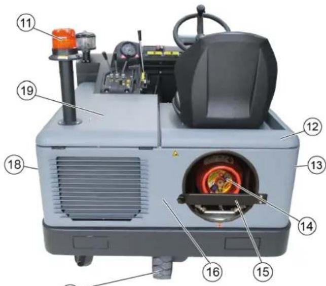


D
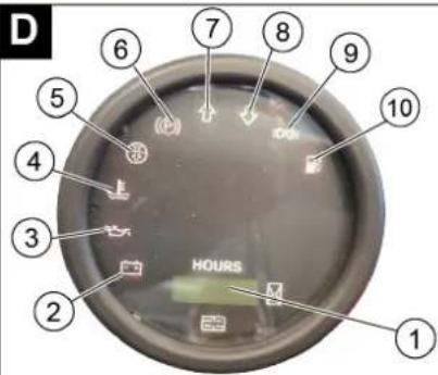
清扫机图片 操作区
图A
1 铭牌
2 座位 (带座位接触开关)
3 方向盘
4 离心力分离器
5 设备外罩锁定装置
6 设备罩
7 右部侧刷
8 前轮
9 消扫辊入口
10 固定拖拉点
11 旋转警示灯
12 右侧护盖
13 右侧保护盖
14 气瓶
15 保险杠
16 尾板
17 后轮
18 左侧保护盖
19 左侧护盖 (发动机盖)
图B
1 扫辊和侧刷操作杆
1 气瓶
2 保险杠
3 封箍
natural_image
Diagram of a mechanical valve assembly with a rotating arrow indicating clockwise motion (no text or labels)→ 沿逆时针方向转动打开抽气阀。
启动设备
→ 开启鼓风机。
→ 清扫平面时:
扫辊和侧刷操作杆(1)向后:扫辊启动。
扫辊操作杆(3)向后:扫辊降下。
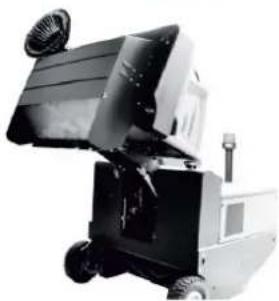
natural_image
Black and white photo of a small industrial machine with wheels and a fan (no visible text or symbols)natural_image
Electrical testing setup with a device connected to a battery pack and cable (no visible text or symbols)→ 拧出所有电池封罩。
(仅适用于保养不足的电池)
1 保险杠支架
2 刹车液容器
3 封盖
natural_image
Close-up of an internal combustion engine bay with hoses and components (no visible text or symbols)1 加油螺栓 (电机)
2 测油棒
natural_image
Close-up of a mechanical engine component with labeled parts (1 and 2), no visible text or symbols beyond labels1 放油螺丝
2 机油过滤器
1 冷却液补偿罐
natural_image
Close-up of a dark metal vehicle's side panel with a tire and a small mechanical component labeled '2' (no readable text or symbols)natural_image
Interior view of a mechanical or industrial enclosure with visible structural beams and components (no text or symbols)natural_image
Abstract geometric pattern with diagonal stripes and a blue upward arrow (no text or symbols)natural_image
Close-up of a mechanical assembly with labeled parts (1 and 2), showing a red tool inserted into a black panel and connected cables (no text or symbols visible)1 保险杠支架
2 保险杠
→ 如 “更换清扫辊” 一章所述,打开侧面外壳。
→ 开启手动过滤器清洁。
检查 / 更换灰尘过滤器
警告
受伤危险
natural_image
Exterior view of a slatted metal grate with numbered annotations (1, 2) pointing to structural elements (no readable text or symbols)natural_image
Technical line drawing of a mechanical assembly with gears and springs (no text or symbols)natural_image
Close-up of a mechanical or industrial device with visible wiring, tubing, and a numbered label (1) in the corner.1 FU 1 保险装置 (主保险装置)
natural_image
Close-up of industrial machinery components with visible wiring and control labels (no readable text or symbols)1 IF المصدر
natural_image
Technical diagram of a mechanical component with labeled parts (1 and 2), showing internal structure without any readable text or symbols.natural_image
Technical line drawing of a mechanical assembly with gears and linkages (no text or symbols)natural_image
Close-up of a mechanical assembly with labeled parts (1 and 2), showing internal components like wires, connectors, and a red tool inserted into a gray panel (no readable text or symbols)natural_image
Interior view of a stainless steel industrial chamber with visible ductwork and structural connections (no text or symbols)1 دعامة التwyت
2 الصامولة المجنسحة
تَل التبريد 1
← المحرك
. باردا
← سائل
التبريد.
natural_image
Close-up of a mechanical engine component with labeled parts (1 and 2), no visible text or symbols beyond labels1 برغي تصريف الزيت
2 فلتر زيت المحرك
natural_image
Close-up of an internal combustion engine bay with hoses and components (no visible text or symbols)1 حامل قضيب التأمين
2 حاوية سائل الفرام
3 سدادة الغلق
ت Winning because Konse.
تفريع خزان القمامة
خط
خطر الإصابة!

natural_image
Black and white photo of a small industrial machine with wheels and a mounted panel (no visible text or symbols)قم بتشغيل المروحة.
ت Winning because Konss.
قيادة الجهاز
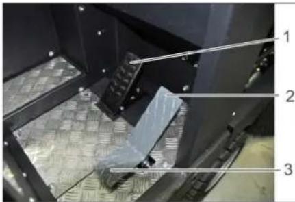
natural_image
Close-up of a mechanical assembly with three numbered parts (1, 2, 3) and a textured floor panel, no visible text or symbols.1 دواسة الفرام
natural_image
Diagram of a medical or laboratory procedure showing a device with tubing and a circular component, no text or symbols present.← اتجاه
1 اسطوانة غاز
2 قضيب التأمين

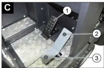
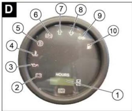
natural_image
Black silhouette of a hand giving a thumbs-up gesture (no text or symbols)THANK YOU!
MERCI! DANKE! iGRACIAS!
Registrieren Sie Ihr Produkt und profitieren Sie von vielen Vorteilen. Register your product and benefit from many advantages. Enregistrez votre produit et bénéficier de nombreux avantages. Registre su producto y aproveche de muchas ventajas.
www.kaercher.com/welcome

Bewerten Sie Ihr Produkt und sagen Sie uns Ihre Meinung. Rate your product and tell us your opinion. Évaluer votre produit et dites-nous votre opinion. Reseñe su producto y díganos su opinión.

natural_image
Icon showing a gear and wrench, no text or symbols presentwww.kaercher.com/dealersearch
Alfred Kärcher SE & Co. KG
Alfred-Kärcher-Str. 28-40
71364 Winnenden (Germany)
Tel.: +49 7195 14-0
Fax: +49 7195 14-2212