KM 105180 R Bp Pack Classic - Sweeper Kärcher - Free user manual and instructions
Find the device manual for free KM 105180 R Bp Pack Classic Kärcher in PDF.
| Product Type | Self-propelled sweeper |
| Brand | Kärcher |
| Model | KM 105/180 R Bp Pack Classic |
| Power supply | Battery 36 V, 240 Ah, low maintenance |
| Dimensions (L × W × H) | 1847 × 1065 × 1388 mm |
| Weight (with batteries) | 860 kg |
| Sweeping width (with 1 side broom) | 1050 mm |
| Dust bin capacity | 180 L |
| Max. unloading height | 1340 mm |
| Forward speed | 6 km/h |
| Max. gradient (driving direction) | 14 % |
| Runtime (full battery) | 2.5 h |
| Protection type | IPX3 |
| Filtration system | Fine dust filter (5.2 m²) |
| Main functions | Sweeping, fine dust vacuuming, edge cleaning |
| Maintenance and cleaning | Manual filter cleaning, regular maintenance by customer and after-sales service |
| Safety | Contact seat, parking brake, slope protection, protective roof (option) |
| Spare parts and repairability | Kärcher authorized accessories and spare parts |
| General information | Industrial and commercial use, indoor/outdoor |
Frequently Asked Questions - KM 105180 R Bp Pack Classic Kärcher
User questions about KM 105180 R Bp Pack Classic Kärcher
0 question about this device. Answer the ones you know or ask your own.
Ask a new question about this device
Download the instructions for your Sweeper in PDF format for free! Find your manual KM 105180 R Bp Pack Classic - Kärcher and take your electronic device back in hand. On this page are published all the documents necessary for the use of your device. KM 105180 R Bp Pack Classic by Kärcher.
USER MANUAL KM 105180 R Bp Pack Classic Kärcher
natural_image
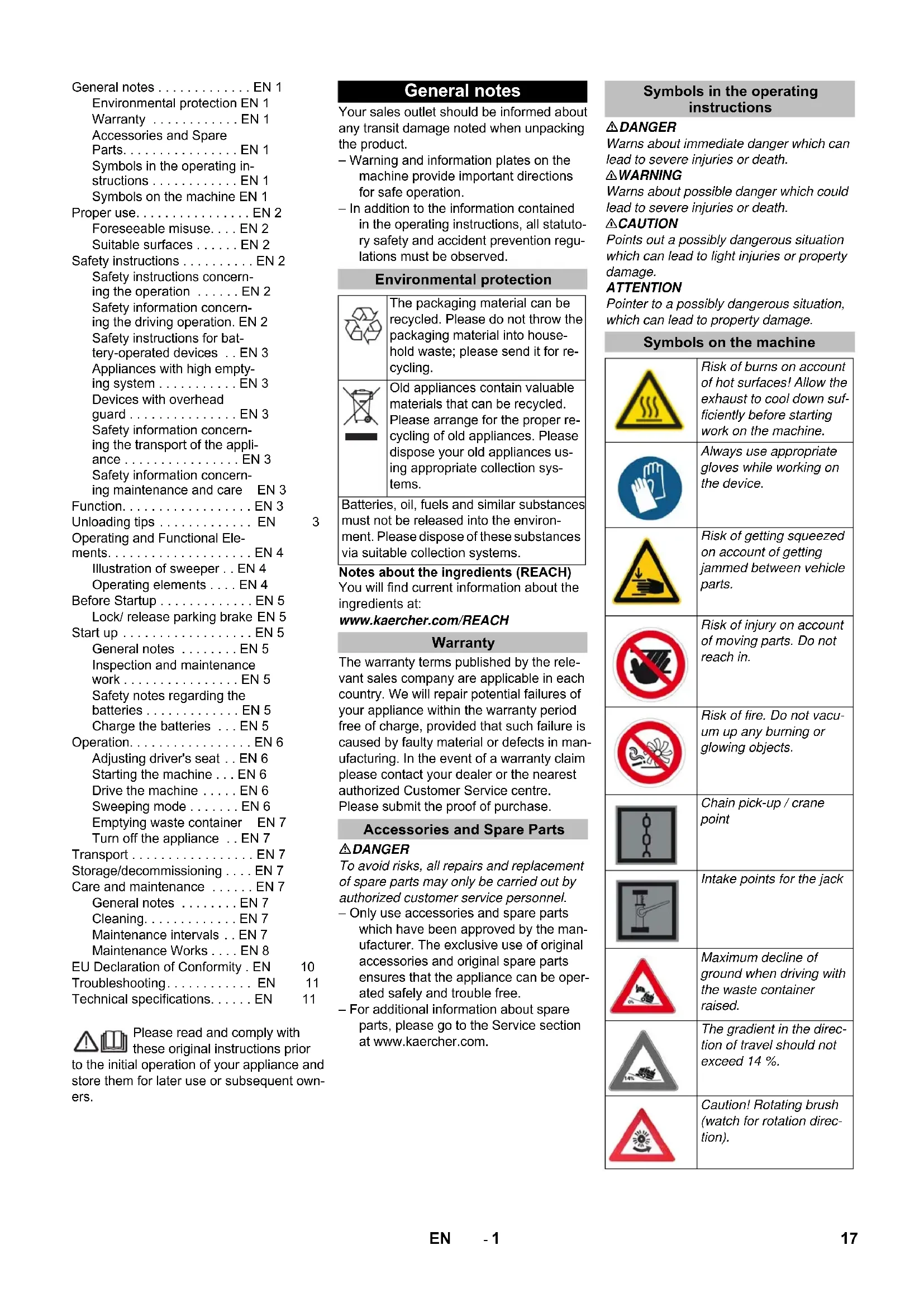
Exterior view of a Karcher industrial cleaning robot with visible brush and control panel (no text or symbols on the device itself)Deutsch 5
English 17
Français 41
Italiano 53
Nederlands 65
Español 77
Português 89
Dansk 101
Norsk 113
Svenska 125
Suomi 137
Ελληνικά 149
Türkçe 162
Русский 174
Magyar 188
Čeština 200
Slovenščina 212
Polski 224
Românește 236
Slovenčina 248
Hrvatski 260
Srpski 272
Български 284
Eesti 297
Latviešu 309
Lietuviškai 321
Українська 333
中文 346
العربية 365
18 Schlüssel Kehrwalzenzugang
natural_image
Close-up of a mechanical component with labeled parts 1 and 2, showing no readable text or symbols.natural_image
Close-up of a car interior control panel with indicator lights and a white arrow pointing to the next button (no text or symbols visible)
natural_image
Exterior view of a black industrial machine with yellow fan and wheels (no visible text or symbols)natural_image
Interior view of an electric vehicle battery pack with labeled components (no text or symbols visible)1 Schauglas
1 Kehrgutbehälter
2 Sicherungsstange
3 Kehrwalze
natural_image
Diagram of a layered structure with a blue upward arrow, no text or symbols present
Chairman of the Board of Management

Director Regulatory Affairs & Certification
71364 Winnenden (Germany)
Tel.: +49 7195 14-0
Fax: +49 7195 14-2212
Winnenden, 2020/01/01
Hilfe bei Störungen
General notes ..... EN 1
Environmental protection EN 1
Warranty ..... EN 1
Accessories and Spare Parts....EN 1
Symbols in the operating instructions ..... EN 1
Symbols on the machine EN 1
Proper use.....EN 2
Foreseeable misuse....EN 2
Suitable surfaces ..... EN 2
Safety instructions ..... EN 2
Safety instructions concerning the operation ..... EN 2
Safety information concerning the driving operation. EN 2
Safety instructions for bat- tery-operated devices .. EN 3
Appliances with high emptying system ....EN 3
Devices with overhead guard....EN 3
Safety information concerning the transport of the appliance ..... EN 3
Safety information concern- ing maintenance and care EN 3
Function.....EN 3
Unloading tips ..... EN 3
Operating and Functional Ele-
ments.....EN 4
Illustration of sweeper .. EN 4
Operating elements .... EN 4
Before Startup ..... EN 5
Lock/ release parking brake EN 5
Start up....EN 5
General notes ..... EN 5
Inspection and maintenance work....EN 5
Safety notes regarding the batteries ..... EN 5
Charge the batteries ... EN 5
Operation.....EN 6
Adjusting driver's seat .. EN 6
Starting the machine ... EN 6
Drive the machine ..... EN 6
Sweeping mode ..... EN 6
Emptying waste container EN 7
Turn off the appliance .. EN 7
Transport......EN 7
Storage/decommissioning .... EN 7
Care and maintenance ..... EN 7
General notes ..... EN 7
Cleaning.....EN 7
Maintenance intervals .. EN 7
Maintenance Works .... EN 8
EU Declaration of Conformity. EN 10
Troubleshooting..... EN 11
Technical specifications.....EN 11
Please read and comply with these original instructions prior
to the initial operation of your appliance and store them for later use or subsequent owners.
General notes
Your sales outlet should be informed about any transit damage noted when unpacking the product.
- Warning and information plates on the machine provide important directions for safe operation.
– In addition to the information contained in the operating instructions, all statutory safety and accident prevention regulations must be observed.
Environmental protection
| The packaging material can be recycled. Please do not throw the packaging material into household waste; please send it for recycling. | |
| Old appliances contain valuable materials that can be recycled. Please arrange for the proper recycling of old appliances. Please dispose your old appliances using appropriate collection systems. |
Batteries, oil, fuels and similar substances must not be released into the environment. Please dispose of these substances via suitable collection systems.
Notes about the ingredients (REACH)
You will find current information about the ingredients at:
www.kaercher.com/REACH
Warranty
The warranty terms published by the relevant sales company are applicable in each country. We will repair potential failures of your appliance within the warranty period free of charge, provided that such failure is caused by faulty material or defects in manufacturing. In the event of a warranty claim please contact your dealer or the nearest authorized Customer Service centre. Please submit the proof of purchase.
Accessories and Spare Parts
△DANGER
To avoid risks, all repairs and replacement of spare parts may only be carried out by authorized customer service personnel.
- Only use accessories and spare parts which have been approved by the manufacturer. The exclusive use of original accessories and original spare parts ensures that the appliance can be operated safely and trouble free.
- For additional information about spare parts, please go to the Service section at www.kaercher.com.
Symbols in the operating instructions
△DANGER
Warns about immediate danger which can lead to severe injuries or death.
⚠ WARNING
Warns about possible danger which could lead to severe injuries or death.
△CAUTION
Points out a possibly dangerous situation which can lead to light injuries or property damage.
ATTENTION
Pointer to a possibly dangerous situation, which can lead to property damage.
Symbols on the machine
 | Risk of burns on account of hot surfaces! Allow the exhaust to cool down sufficiently before starting work on the machine. |
 | Always use appropriate gloves while working on the device. |
 | Risk of getting squeezed on account of getting jammed between vehicle parts. |
 | Risk of injury on account of moving parts. Do not reach in. |
 | Risk of fire. Do not vacuum up any burning or glowing objects. |
 | Chain pick-up / crane point |
 | Intake points for the jack |
 | Maximum decline of ground when driving with the waste container raised. |
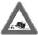 | The gradient in the direction of travel should not exceed 14 %. |
 | Caution! Rotating brush (watch for rotation direction). |
| Beware of dangerous electrical current! | |
| Pay attention to the instruction. | |
| Steer slowly! | |
| Please read the operating instructions and act accordingly! | |
| Risk of damage!Do not wash the fine dust filter. |
Proper use
The sweeper is intended for cleaning floor surfaces for commercial use and e.g. for the following fields of application:
Car parks
■ Production facilities
■ Logistics areas
Hotel
■ Retail industry
■ Storage areas
■ Walkways
- This sweeper has been designed to sweep dirt and debris from indoor as well as outdoor surfaces.
- The machine with working equipment must be checked to ensure that it is in proper working order and is operating safely prior to use. Otherwise, the appliance must not be used.
- Use this sweeper only as directed in these operating instructions.
– The machine may not be modified. - The machine is only suitable for use on the types of surfaces specified in the operating instructions.
– The machine may only be operated on the surfaces approved by the company or its authorised representatives. - The following applies in general: Keep highly-flammable substances away from the appliance (danger of explosion/fire).
Foreseeable misuse
→ Never vacuum up explosive liquids, combustible gases or undiluted acids and solvents. This includes petrol, paint thinner or heating oil which can generate explosive fumes or mixtures upon contact with the suction air. Acetone, undiluted acids and solvents must also be avoided as they can harm the materials on the machine.
→ Never sweep/vacuum up reactive metal dusts (e.g. aluminium, magnesium, zinc), as they form explosive gases when they come in contact with highly alkaline or acidic detergents.
→ Do not sweep/vacuum up any burning or glowing objects.
→ The appliance is not suitable for sweeping off hazardous substances.
→ The machine may not be used or stored in hazardous areas. It is not allowed to use the appliance in hazardous locations.
→ It is strictly prohibited to take co-passengers.
→ Pushing/pulling or transporting objects by means of this appliance is prohibited.
Suitable surfaces
- Asphalt
- Industrial floor
- Screed
- Concrete
- Paving stones
Safety instructions
Safety instructions concerning the operation
→ In order to maintain clearance and creepage distances, the device may not be operated over 2000 metres above sea level.
→ (Applicable for Finland only) The device may not be used at low ambient temperatures (below 0°C) if it is equipped with a PVC hose line. Contact Kärcher if should have questions regarding your device.
→ The machine with working equipment must be checked to ensure that it is in proper working order and is operating safely prior to use. Otherwise, the appliance must not be used.
→ If the appliance is used in hazardous areas (e.g. filling stations) the corresponding safety provisions must be observed. It is not allowed to use the appliance in hazardous locations.
△DANGER
Risk of injury!
→ Do not use the appliance without an overhead guard in areas where the operator might get hit by falling objects.
→ The operator must use the appliance properly. The person must consider the local conditions and must pay attention to third parties, in particular children, when working with the appliance.
→ It is important to follow all safety instructions, rules and regulations applicable for driving motor vehicles.
→ Prior to starting work, the operator must ensure that all protective devices are properly installed and function correctly.
→ The operator of the appliance is liable for accidents with other individuals or their property.
→ Ensure that the operator wears tight-fitting clothes. Wear sturdy shoes and avoid wearing loose-fitting clothes.
→ Check the immediate vicinity prior to starting (e.g. children). Ensure sufficient visibility!
→ Never leave the machine unattended so long as the engine is running. The operator may leave the appliance only when the engine has come to a standstill, the appliance has been protected against accidental movement, and the key has been removed.
→ Please remove the key, when not in use, to avoid unauthorised use of the appliance.
The appliance may only be used by persons who have been instructed in handling the appliance or have proven qualification and expertise in operating the appliance or have been explicitly assigned the task of handling the appliance.
→ This appliance is not intended for use by persons (including children) with limited physical, sensoric or mental capacities or lack of experience and/or skills, unless such persons are accompanied and supervised by a person in charge of their safety or if they received precise instructions on the use of this appliance.
→ Children should be supervised to prevent them from playing with the appliance.
CAUTION
Risk of damage! Do not sweep up straps, strings or wires as these may wrap around the brush roller.
Safety information concerning the driving operation
△DANGER
Risk of injury! Verify the stability of the ground prior to driving on it.
△DANGER
Risk of accident, risk of injury!
Danger of tipping if gradient is too high.
– The gradient in the direction of travel should not exceed 14 %.
Danger of tipping over when taking bends at high speed (particularly left-hand bends).
- Drive slowly when cornering.
Danger of tipping on unstable ground.
- Only use the machine on sound surfaces.
Danger of tipping with excessive sideways tilt.
- The gradient perpendicular to the direction of travel should not exceed 10% .
Safety instructions for battery-operated devices
Note: Warranty claims will be entertained only if you use batteries and chargers recommended by Kärcher.
- Always follow the instructions of the battery manufacturer and the charger manufacturer. Please follow the statutory requirements for handling and disposing batteries.
– Never leave the batteries in a discharged state; recharge them as soon as possible. - Always keep the batteries clean and dry to avoid creep currents. Protect the batteries and avoid contact with impurities such as metal dust.
- Do not place tools or similar items on the battery. Risk of short-circuit and explosion.
- Do not work with open flames, generate sparks or smoke in the vicinity of a battery or a battery charging room. Danger of explosion.
- Do not touch hot parts of the machine such as the drive motor (risk of burns).
- Be careful while handling battery acid. Follow the respective safety instructions!
– Used batteries are to be disposed according to the EC guideline 91/157 EWG in an environment-friendly manner.
Appliances with high emptying system
△DANGER
Risk of injury!
→ When working on the high emptying system, completely lift and secure the waste container.
→ Perform the safeguarding only from outside the hazard zone.
Devices with overhead guard
NOTICE
The overhead guard (optional) protects the driver against larger falling objects. However, it does not provide rollover protection!
→ Check the overhead guard for damage daily.
→ If the overhead guard, as well as individual elements, should be damaged, replace the entire overhead guard.
→ Any modification of the overhead guard and installation of elements, components and assemblies other than those approved by Kärcher is not permitted and may limit the function of the overhead guard.
Safety information concerning the transport of the appliance
→ Observe the net weight (transport weight) of the device during transport on trailers or vehicles.
→ To transport the device, unplug the battery plug and securely fasten the device.
Safety information concerning maintenance and care
→ First switch off the appliance and remove the key before performing any cleaning or maintenance tasks on the appliance, replacing parts or switching over to another function.
→ When performing any service and maintenance work on devices with a traction battery, the battery must be disconnected from the electrical system of the device via the battery isolation point (battery plug).
→ Always disconnect the battery when working on the electrics.
To do this, first disconnect the negative terminal and then the positive terminal. Reconnection is performed in reverse sequence. Connect the positive terminal first, then connect the negative terminal.
Do not clean the appliance with a water hose or high-pressure water jet (danger of short circuits or other damage).
→ Maintenance work may only be carried out by approved customer service outlets or experts in this field who are familiar with the respective safety regulations.
→ Please observe the local safety regulations regarding portable commercially used appliances.
→ Always use appropriate gloves while working on the device.
Function
The sweeper operates using the sweep-shovel principle.
- The rotating roller brush moves the dirt directly into the waste container.
- The side brush cleans the corners and edges of the surface and moves dirt and debris into the path of the roller brush.
- The fine dust is sucked in via the dust filter through the suction blower.
Unloading tips
⚠ Danger
Risk of injury, risk of damage! Observe the weight of the appliance when you load it!
| Weight (without batteries) 560 kg* | |
| Weight (with batteries) 860 kg* | |
| * If upgrade kits are installed, the weight is respectively higher. | |
→ Do not use a forklift.
→ Use a suitable ramp or a crane to load the appliance!
→ Observe when using a ramp: Ground clearance 70 mm.
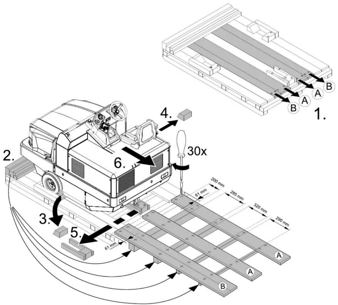
→ If the machine is delivered on a pallet, you must create an unloading ramp using the boards provided.
You will find the instructions for this procedure on page 2 (inside of cover).
Important instruction: every board must be attached with at least 2 screws.
Operating and Functional Elements
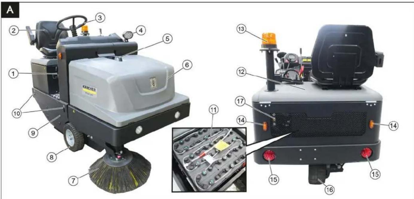
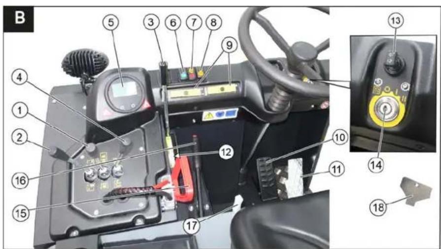
Illustration of sweeper Operating elements
Illustration A
1 Nameplate
2 Seat (with seat contact switch)
3 Steering wheel
4 Blue Spot (option)
5 Handle with locking button
6 Cover
7 Side brush, right
8 Front wheel
9 Roller brush access
10 Lashing point
11 Battery set
(only included with the scope of delivery for the KM 105/180 R Bp Pack)
12 Engine bonnet
13 Beacon lamp
14 Blinker (option)
15 Taillights (option)
16 Drive wheel
17 Sight glass hydraulic oil
Illustration B
1 Roller brush and side brush control lever
Lever forwards: Switches the roller brush on and lowers and switches the side brushes on.
Lever backwards: Switches the roller brush on
2 Control lever waste container Raise/lower waste container
3 Roller brush control lever Raises and lowers the roller brush
4 Control lever container flap Open/close container lid
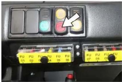
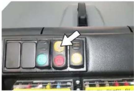
5 Indicator lamps and display
6 Switch for lights (option)
7 Switch blower and filter cleaning Position centred: Filter cleaning and blower off
Front position: Blower on Rear position: Filter cleaning on
8 Horn switch
9 Fuses
10 Brake pedal
11 Accelerator pedal forward / reverse
12 Roller brush wear adjustment / sweeping area setting
13 Turn signal switch (option)
14 Ignition lock
Position 0: Switch off engine
Position 1: Ignition on
Position 2: Start the engine
15 Battery socket
16 Parking brake
17 Lever for seat adjustment
18 Key for roller brush access
Indicator lamps and display
Illustration ©
1 Display (battery capacity)
2 Battery charger control
3 Working light indicator light
4 Indicator lamp for direction indicator
5 Indicator light flap waste container open
6 Warning light flap waste container closed
7 not assigned
8 Filter cleaning display active
9 not assigned
Before Startup
Lock/ release parking brake
→ Loosen parking brake; press brake pedal at the same time.
→ Activate the parking brake; press brake pedal at the same time.
Start up
General notes
→ Park the sweeper on an even surface.
→ Remove ignition key.
→ Lock parking brake.
Inspection and maintenance work
Daily before starting operations
→ Check battery charging status; charge batteries it if required (see Chapter "Charging the batteries").
→ Check the sweeping roller and the side brush for wear and wrapped belts.
→ Check the wheels for tied up belts.
→ Check function of all operator control elements.
→ Check appliance for damages.
Note: For description, see section on Care and maintenance.
Safety notes regarding the batteries
Please observe the following warning notes when handling batteries:
| Observe the directions on the battery, in the instructions for use and in the vehicle operating instructions! | |
| Wear an eye shield! | |
| Keep away children from acid and batteries! | |
| Risk of explosion! | |
| Fire, sparks, open light, and smoking not allowed! | |
| Danger of causticization! | |
| First aid! | |
| Warning note! | |
| Disposal! |

Pb
Do not throw the battery in the dustbin!

Beware of dangerous electrical current!
Danger
Risk of explosion! Do not put tools or similar on the battery, i.e. on the terminal poles and cell connectors.
⚠ Danger
Risk of injury! Ensure that wounds never come into contact with lead. Always clean your hands after having worked with batteries.
△DANGER
Risk of fire and explosion!
- Smoking and naked flames are strictly prohibited.
- Rooms where batteries are charged must have good ventilation because highly explosive gas is emitted during charging.
⚠ Danger
Danger of causticization!
- Rinse thoroughly with lots of clear water if acid gets into the eye or comes in contact with the skin.
- Then consult a doctor immediately.
- Wash off the acid If it comes in contact with the clothes.
Charge the batteries
CAUTION
Charge the batteries before commissioning the machine.
△DANGER
Risk of injury! Observe the safety instructions on the handling of batteries. Follow the instructions of the charger manufacturer.
Please read and follow the included operating instructions by the battery manufacturer and follow them.
Charge the battery only with an appropriate charger.
△DANGER
Risk of acid burns. Refilling water when the battery is in the discharged state can lead to acid leakage! When handling battery acid, use safety goggles and observe regulations to prevent injury and destruction of clothing. Immediately rinse off any splashed acid from the skin or clothing using copious amounts of water.
CAUTION
Risk of damage. Use only distilled or desalinated water (VDE 0510) for filling the battery. Do not add any substances (so-called performance improving agents), else warranty claims will not be entertained.
→ Park the device safely in dry rooms with adequate ventilation.
→ Open the engine hood.
Note: The cover must remain open during the charging process.
→ Pull the battery plug from the machine and connect it to the plug of the charger.
→ Connect the plug of the charger to a proper socket of 16 A, the charger will charge automatically.
→ Execute ta charging process according to the information in the operating instructions of the charger.
The recommended chargers (suitable for the batteries used) are regulated electronically and will automatically terminate the charging process.
→ Note: When the batteries are charged, first remove the charger from the mains and then disconnect it from the batteries.
Recommended batteries, chargers
Note
The 105/180 R Bp Pack sweeper variant (1.186-051.0) is already supplied with batteries and charger.
The 105/180 R Bp sweeper variant (1.186-050.0) is supplied without batteries and charger.
We recommend the following batteries and chargers:
| Order number | |
| Battery pack 36 V, 240 Ah, (in the trough, low maintenance) * | 6,981-067.0 |
| Charger 36 V, 40 A 6,981-066.0 | |
| * Appliance requires 1 battery pack | |
The use of other batteries and chargers is not recommended and should be discussed with Kärcher customer service.
Check fluid level in the battery and adjust if required
CAUTION
Be sure to observe the battery manufacturer's instructions and then act accordingly.
Check charging status of battery
The charging state of the battery is shown on the sweeper display.
If the battery charge indicator light is red:
→ Battery is discharged. The sweeping mode will be terminated automatically (the sweeping aggregates cannot be taken into operation until the battery is charged).
→ Drive the machine directly to the charging station; avoid any steep gradients in the process.
→ Charge battery.
Operation
Adjusting driver's seat

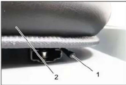
natural_image
Close-up of a mechanical component with labeled parts 1 and 2, no readable text or symbols beyond labels1 Lever for seat adjustment
2 Driver seat
→ Pull seat adjustment lever outwards.
→ Slide seat, release lever and lock in place.
→ Check that the seat is properly locked in position by attempting to move it backwards and forwards.
Starting the machine
Note: The machine is equipped with a seat contact switch If the driver's seat is vacated, the machine is switched off.
Note: The fine dust filter is automatically cleaned when the device is started.
→ Sit on the driver's seat.
→ Lock parking brake.
→ Insert the ignition key into the ignition switch.
→ Turn the ignition key to position "I". The appliance is now ready for operation.
→ Turn the ignition key to position "II".
The appliance can now be driven.
Note: The display of the battery capacity will show the actual charge status after about 10 seconds.
Drive the machine
→ Press brake pedal and keep it depressed.
→ Release parking brake.
Drive forward
→ Slowly press the accelerator pedal to the front.
Reverse drive
⚠ Danger
Risk of injury! While reversing, ensure that there is nobody in the way, ask them to move if somebody is around.
→ Slowly press the accelerator pedal backwards.
Driving method
→ The accelerator pedal can be used to vary the driving speed infinitely.
→ Avoid jerking the pedal.
Brakes
→ Release the accelerator pedal, the machine brakes automatically and stops.
Note: The braking effect can be supported by pressing the brake pedal.
Driving over obstacles
Driving over fixed obstacles which are 70 mm high or less:
→ Drive forwards slowly and carefully. Driving over fixed obstacles which are more than 70 mm high:
→ Only drive over these obstacles using a suitable ramp.
Sweeping mode
ATTENTION
Do not sweep up packing strips, wire or similar objects as this may damage the sweeping mechanism.
Note: To achieve an optimum cleaning result, the driving speed should be adjusted to take specific situations into account.
Note: The fine dust filter is automatically cleaned every 10 minutes during operation.
Note: For increased work in the fine dust area, the filter must also be cleaned by pressing the filter cleaning switch.
Cleaning the fine dust filter manually
→ Clean the fine dust filter with the filter cleaning button.
Control lever

1 Roller brush and side brush control lever
2 Control lever waste container
3 Roller brush control lever
4 Control lever container flap
Roller brush and side brush control le-
ver
→ Control lever (1) forwards: Switches the roller brush on and lowers and switches the side brushes on.
→ Control lever (1) backwards: Switches the roller brush on.
Control lever waste container
→ Control lever waste container (2) to the front: Waste container is lowered.
→ Control lever waste container (2) to the back: Waste container is raised.
Control lever roller brush
→ Roller brush control lever (3) forwards: Raises the roller brush.
→ Roller brush control lever (3) backwards: Lowers the roller brush.
Control lever container flap
→ Control lever container flap (4) to the front: The container flap of the waste container opens.
Note: The green indicator lamp must light up.
→ Control lever container flap (4) to the back: The container flap of the waste container closes.
Note: The red indicator lamp must light up.
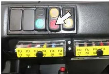
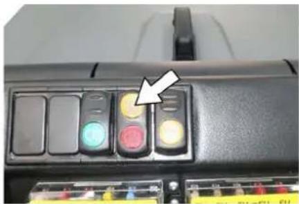
Sweeping dry floors
natural_image
Close-up of a computer control panel with four buttons and a highlighted arrow pointing to one (no visible text or symbols)→ Switch on the blower.
→ With surface cleaning:
Roller brush and side brush control lever (1) backwards: Switches the roller brush on.
Roller brush control lever (3) backwards: Lowers the roller brush.
→ Control lever container flap (4) to the front: Container flap opens.
Note: The green indicator lamp must light up.
→ With cleaning of side edges:
Roller brush and side brush control lever (1) forwards: Switches the roller brush on, switches the side brushes on and lowers them.
Roller brush control lever (3) backwards: Lowers the roller brush.
Sweeping damp or wet floors
→ Switch off the blower.
→ With surface cleaning:
Roller brush and side brush control lever (1) backwards: Switches the roller brush on.
Roller brush control lever (3) backwards: Lowers the roller brush.
→ Control lever container flap (4) to the front: Container flap opens.
Note: The green indicator lamp must light up.
→ With cleaning of side edges:
Roller brush and side brush control lever (1) forwards: Switches the roller brush on, switches the side brushes on and lowers them.
Roller brush control lever (3) backwards: Lowers the roller brush.
Emptying waste container
△DANGER
Risk of injury!
→ During the emptying process, persons and animals must not stay within the swivelling range of the waste container.
Danger of tipping!
→ Place the device on an even surface during the emptying process.
⚠ WARNING
Risk of crushing!
→ Never reach into the rod assembly for the drainage mechanism. Do not stay under the raised container.
ATTENTION
Risk of personal injury or damage!
→ Material of the rotating roller brush may be catapulted off during the emptying process. Keep an appropriate distance.


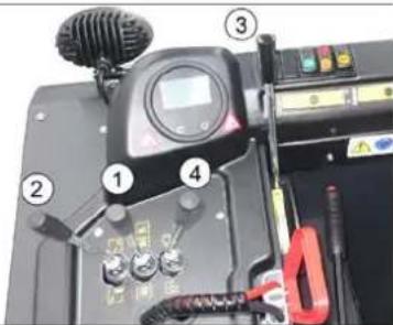
natural_image
Exterior view of a black industrial machine with yellow fan and wheels (no visible text or symbols)→ Raise the roller brush and side brushes using the control levers: Control lever 1 to middle position and control lever 3 forwards.
→ Close the container flap, in order to do so, move the control lever (4) to the back:
Note: The green indicator lamp must light up.
→ Raise the container flap, in order to do so, move the waste container control lever (2) to the back:
→ Slowly drive towards the collection container.
→ Lock parking brake.
→ Open the container flap, in order to do so, push the container flap operating lever (4) to the front and empty the waste container.
Note: The red indicator lamp must light up.
→ Close the container flap, in order to do so, push the container flap operating lever (4) to the back until it is tipped inwards in the end position.
Note: The green indicator lamp must light up.
→ Release parking brake.
→ Drive away the collection container slowly.
→ Lower the waste container into the end position, in order to do so, move the waste container control lever (2) to the front
Turn off the appliance
→ Press brake pedal and keep it depressed.
→ Lock parking brake.
→ Turn ignition key to "0" and remove it.
Transport
△DANGER
Transport damage!
→ Observe the net weight (transport weight) of the device during transport on trailers or vehicles.
→ When transporting in vehicles, secure the appliance according to the guidelines from slipping and tipping over.
→ Turn ignition key to "0" and remove it.
→ Lock parking brake.
→ Secure the appliance at the lashing points (4x) using tension belts, ropes or chains.
→ Secure the wheels of the machine with wheel chocks.
→ Disconnect the battery of the sweeper during transport.
Storage/decommissioning
△DANGER
Risk of injury and damage! Note the weight of the appliance in case of storage.
→ Park the sweeper on a level surface in a dry, frost protected area. Protect it against dust by means of covering material.
→ Raise the roller brush and the side-brushes to prevent the bristles from being damaged.
→ Close the container flap.
→ Turn ignition key to "0" and remove it.
→ Lock parking brake.
→ Lock the sweeper to ensure that it does not roll off.
Additionally observe the following points if the sweeper is not used over a longer period of time:
→ Clean the inside and outside of the sweeper.
→ Remove the battery plug from machine.
→ Charge battery and recharge it approx. every 2 months.
Care and maintenance
△CAUTION
Risk of damage due to short circuit!
→ When working on the electrical system or before opening electrical covers, the battery must be disconnected or the battery connector disconnected.
ATTENTION
Risk of damage!
→ Do not wash the fine dust filter.
→ Maintenance work may only be carried out by approved customer service outlets or experts in this field who are familiar with the respective safety regulations.
→ Mobile appliances used for commercial purposes are subject to safety inspections according to VDE 0701.
General notes
→ Park the sweeper on an even surface.
→ Turn ignition key to "0" and remove it.
→ Lock parking brake.
Cleaning
CAUTION
Risk of damage!
Do not clean the appliance with a water hose or high-pressure water jet (danger of short circuits or other damage).
Cleaning the inside of the machine
⚠️ DANGER
Risk of injury!
→ Wear dust mask and protective goggles.
→ Clean machine with a cloth.
→ Blow through machine with compressed air.
External cleaning of the appliance
→ Clean the machine with a damp cloth which has been soaked in mild detergent.
Note: Do not use aggressive cleaning agents.
Maintenance intervals
Note: The elapsed-time counter shows the timing of the maintenance intervals.
Maintenance by the customer
Note: Where maintenance is carried out by the customer, all service and maintenance work must be undertaken by a qualified specialist. If required, a specialised Kärcher dealer may be contacted at any time.
Daily maintenance:
→ Check battery charging status; charge batteries it if required (see Chapter "Charging the batteries").
→ Check the sweeping roller and the side brush for wear and wrapped belts.
→ Check the wheels for tied up belts.
→ Check function of all operator control elements.
→ Check appliance for damages.
→ Clean the dust filter with the filter cleaning button.
Weekly maintenance:
→ Check hydraulic unit.
→ Check the hydraulic oil level.
→ Check brake fluid status.
→ Check the pad for wear, replace if required.
→ Check the container lid and lubricate it.
Maintenance following wear:
→ Replace sealing strips.
→ Readjust the side seals or replace them.
→ Replace roller brush.
→ Replace side brush.
Note: For description, see section on Maintenance work.
Maintenance by Customer Service
Maintenance to be carried out after 50 operating hours:
→ Have the first maintenance performed by the customer service in accordance with the inspection check list.
Maintenance to be carried out after 250 operating hours:
→ Have the maintenance performed by the customer service in accordance with the inspection check list.
In order to safeguard warranty claims, all service and maintenance work during the warranty period must be carried out by the authorised Kärcher Customer Service in accordance with the maintenance booklet.
Maintenance Works
Preparation:
→ Park the sweeper on an even surface.
→ Turn ignition key to "0" and remove it.
→ Lock parking brake.
Securing the raised waste container ⚠️DANGER
Risk of injury! Always apply the safety bar when the waste container is raised. Perform the safeguarding only from outside the hazard zone.

1 Holder of safety rod
2 Safety rod
→ Fold the safety rod for the high emptying up and insert it into the holder (secured).
Replace batteries
ATTENTION
Observe the orientation of the battery terminals when installing the batteries. Battery terminals are installed on the left in the direction of travel.
The batteries can only be exchanged as a set. The exchange has to be performed by trained personnel.
→ Due to the heavy weight (300 kg), the batteries must be exchanged using a crane.
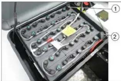
natural_image
Interior view of a battery pack with multiple charging cells and wiring, labeled with numbers 1 and 2 (no text or symbols on the diagram itself)Battery terminals - travel direction left
1 Negative terminal
2 Positive terminal
→ When removing the battery, disconnect the negative terminal wire first. → Fasten the crane chains in the four eyelets of the battery set and carefully lift out the batteries.
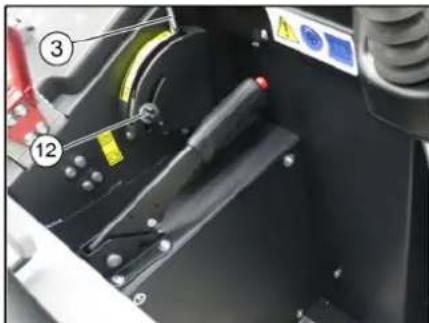
Check hydraulic oil level and refill hydraulic oil
NOTICE
The waste container must not be raised.
→ Open the engine hood.
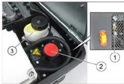
1 Looking glass
2 Screw cap, oil fill opening
3 Container (without function)
→ Check hydraulic oil level in the looking glass.
- The oil level must lie between "MIN" and "MAX" marking.
- Add hydraulic oil if the oil level is below the "MIN" marking.
→ Loosen the closing cap of the oil filling opening.
→ Clean the filling area.
→ Refill hydraulic oil.
Oil grade: see Technical Data
→ Replace and tighten the closing cap of the oil filling opening.
Check hydraulic unit
→ Lock parking brake.
→ Start the motor.
Only the authorised customer service is permitted to carry out maintenance tasks on the hydraulic unit.
→ Check all hydraulic hoses and connections and ensure that they are leak-proof.
Checking roller brush
△DANGER
Risk of injury! Always apply the safety bar when the waste container is raised.
Perform the safeguarding only from outside the hazard zone.

1 Waste container
2 Safety rod
3 Roller brush
→ Switch off device.
→ Lift the emptied waste container to the end position. The roller brush is visible. Secure the waste container. See chapter "Securing the raised waste container".
→ Turn ignition key to "0" and remove it.
→ Check the roller brush for damage, remove wrapped tapes or cords.
→ Fold the safety rod down into the receptacle (raised waste container is unsecured).
→ Lower the waste container up to the end-position.
Replacing roller brush
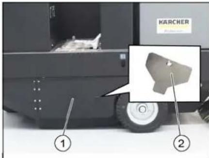
1 Side panel, right
2 Key for roller brush access
→ Lift the emptied waste container to the end position.
Secure the waste container. See chapter "Securing the raised waste container".
→ Open the side covers using a key.
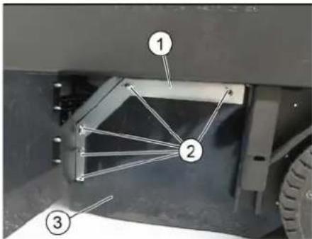
1 Holding bow
2 Wing nut
3 Side seal
→ Unscrew the wing nuts.
→ Remove the retaining clamp.
→ Flip the side seal out.
→ Uncscrew the retaining screw of the roller brush intake, and swing the intake to the outside.
→ Pull out roller brush.
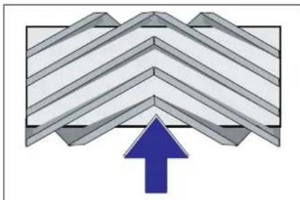
natural_image
Diagram of a folded structure with a blue upward arrow, no text or symbols presentInstallation position of roller brush in direction of travel (top view)
Note: When installing the new roller brush, ensure correct positioning of the bristle assembly.
→ Install new roller brush. The nuts of the roller brush must be inserted on the notches of the opposite crank.
Note: Once the new roller brush has been installed, the sweeping track must readjusted.
Check and adjust roller brush sweeping track
Note: The sweeping track is factory-set to 80 mm; it is steplessly adjustable if the brush roller wears down.
→ Switch off suction blower.
→ Drive sweeper on to a smooth, even surface covered with a visible layer of dust or chalk.
→ Roller brush and side brush control lever (1) backwards: Switches the roller brush on.
Roller brush control lever (3) backwards: Lowers the roller brush.
→ Allow the roller brush to run for approx. 10 seconds.
→ Roller brush and side brush control lever (1) to middle position.
Roller brush control lever (3) forwards: Raises the roller brush.
→ Raise waste container.
→ Drive machine backwards.
→ Check sweeping mirror.
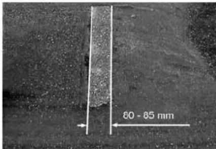
The sweeping track should have an even rectangular shape which is 80-85 mm wide.
→ Undo and adjust the stop screw for wear adjustment (12).
Stop screw at the top: narrow sweeping area.
Stop screw at the bottom: broad sweeping area.
→ Tighten the stop screw again.
→ Check the sweeping area of the roller brush again as described.
Check and adjust sweeping track of the side-brush
→ The side-brushes lift up.
→ Drive sweeper on to a smooth, even surface covered with a visible layer of dust or chalk.
→ Lower the side brushes using the control lever and allow them to run for approx. 10 seconds.
→ The side-brushes lift up.
→ Drive machine backwards.
→ Check sweeping mirror.

The width of the sweeping track should lie between 40-50 mm.
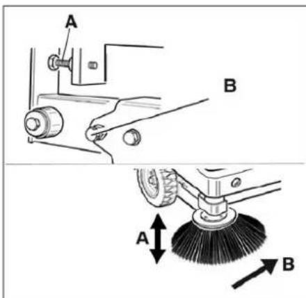
→ Set the sweeping track using the two adjusting screws.
→ Check sweeping mirror.
Adjust the side seals
△DANGER
Risk of injury! Always apply the safety bar when the waste container is raised.
→ Lift the emptied waste container to the end position.
Secure the waste container. See chapter "Securing the raised waste container".
→ Open the side cover as described in Chapter "Replace brush roller".
→ Relase the 6 wing nuts on the side holding plate.
→ Loosen 3 nuts (SW 13) on the front holding plate.
→ Press the side seal down (elongated hole) until it is about 1 to 3 mm to the floor.
→ Screw in the holding plates.
→ Repeat the procedure on the other side of the appliance.
Checking/changing the fine dust filter ⚠ WARNING
Risk of injury!
→ Wear a dust mask when working around the dust filter. Observe safety regulations on the handling of fine particles.
→ Clean the fine dust filter with the filter cleaning button.
→ Empty waste container.

1 Cover
2 Filter cover (vibrator system)
3 Lock, filter cover (2x)
→ Fold cover forwards.

1 Cover
2 Fine dust filter
3 Cross struts
→ Open the lock.
→ Open filter cap.
→ Check the fine dust filter, clean or replace if necessary.
Note
Exchanging the fine dust filter may only be done by Kärcher Customer Service.
→ Insert and lock the filter cover.
Replacing fuses
△CAUTION
Risk of damage!
→ Make sure that the covers of the fuse boxes are not interchanged.
ATTENTION
Only use fuses with identical safety ratings.
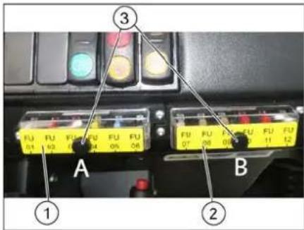
1 Fuse box A
2 Fuse box B
3 Lock nut
→ Unscrew the knurled nut.
→ Open the cover on the fuse box.
→ Check the fuses.
→ Replace defective fuses.
Fuse box A
| FU01 Safety relayStart up | 5 A |
| FU02 Enable DC / DC 10 A | |
| FU03 Beacon lampHorn | 10 A |
| FU04 Suction blower 20 A | |
| FU05 Vibrator system 15 A | |
| FU06 DC / DC input 20 A |
Fuse box B
| FU07 Multifunction display 5 A | |
| FU08 Reverse warning signalFlap indicator | 7.5 A |
| FU09 Safety relaySuction blowerVibrator system | 5 A |
| FU10 Water pump (option) 10 A | |
| FU11 Lighting system (optional)Blinker (option)Blue Spot (option) | 10 A |
| FU12 Shaking system flat fold filter and round filter (option) | 15 A |
Main relay fuse
| FU 13* Main relay 125 A |
* These fuses may only be changed by Customer Service, as it is necessary to check the device for potential faults.
EU Declaration of Conformity
We hereby declare that the machine described below complies with the relevant basic safety and health requirements of the EU Directives, both in its basic design and construction as well as in the version put into circulation by us. This declaration shall cease to be valid if the machine is modified without our prior approval.
Product: Ride-on vacuum sweeper
Type: KM 105/180 R Bp 1,186-050.0 KM 105/180 R Bp Pack 1,186-051.0
Relevant EU Directives
2006/42/EC (+2009/127/EC)
2014/30/EU
2000/14/EC
Applied harmonized standards
EN 60335-1
EN 60335-2-72
EN 55012: 2007 + A1: 2009
EN 61000-6-2: 2005
EN 62233: 2008
Applied conformity evaluation method
2000/14/EC: Appendix V
Sound power level dB(A)
Measured: 90
Guaranteed: 93
The signatories act on behalf of and with the authority of the company management.

Chairman of the Board of Management
S. Reiser
Director Regulatory Affairs & Certification
Documentation supervisor:
S. Reiser
Alfred Kärcher SE & Co. KG
71364 Winnenden (Germany)
Tel.: +49 7195 14-0
Fax: +49 7195 14-2212
Winnenden, 2020/01/01
Troubleshooting
| Fault Remedy | |
| Device does not drive or drives only slowly | Sit on the driver seat, the seat contact switch gets activated. |
| Have the drive motor fuse, FU 13, checked by Customer Service | |
| Charging or replacing battery | |
| Release parking brake | |
| Check for trapped ribbons and strings. | |
| Inform Kärcher Customer Service. | |
| Whistling sound in the hydraulic system | Refill hydraulic fluid |
| Inform Kärcher Customer Service. | |
| Brushes are rotating slowly or not at all | Check for trapped ribbons and strings. |
| Inform Kärcher Customer Service. | |
| Too little or no suction power in the brush area | Clean dust filter |
| Inform Kärcher Customer Service. | |
| Dust gathers in the machine Adjust | the side seals |
| Switch on blower | |
| Clean dust filter | |
| Replace filter washers | |
| Inform Kärcher Customer Service. | |
| Sweeping unit does not pick up waste | Empty waste container |
| Clean dust filter | |
| Replacing roller brush | |
| Adjust sweeping track | |
| Replace sealing strips of the waste container | |
| Remove the blocking of the brush roller | |
| Inform Kärcher Customer Service. | |
| Waste container does not raise or lower | Check the fuses. |
| Remove the locking support from the waste container | |
| Inform Kärcher Customer Service. | |
| Waste container is rotating slowly or not at all | Inform Kärcher Customer Service. |
| Operation problems with hydraulic movement parts | Inform Kärcher Customer Service. |
Technical specifications
| KM 105/180 R Bp Classic | KM 105/180 R Bp Pack Classic | ||
| Machine data | |||
| Drive speed, forward km/h 6 6 | |||
| Drive speed, reverse km/h 3 3 | |||
| Climbing capability (max.) -- 14% 14% | |||
| Surface cleaning performance without side brushes m | ^2/h 4680 4680 | ||
| Surface cleaning performance with 1 side brushes m | ^2/h 6300 6300 | ||
| Working width without side brushes mm 780 | 780 | ||
| Working width with 1 side brushes | mm 1050 1050 | ||
| Protection type, drip-proof | -- IPX 3 | IPX 3 | |
| Usage duration with battery fully charged | h | 2.5 | 2.5 |
| Electrical system | |||
| Battery capacity | V, Ah | --- | 36, 240 |
| Battery set | kg | --- | 300 |
| Hydraulic system | |||
| Hydraulic oil type | -- HV 46 | HV 46 | |
| Waste container | |||
| Max. unloading height | mm 1340 1340 | ||
| Volume of waste container | I | 180 | 180 |
| Roller brush | |||
| Roller brush diameter mm 280 280 | |||
| Roller brush width mm 780 780 | |||
| Speed 1/min 360 360 | |||
| Sweeping track mm 80 80 | |||
| Side brushes | |||
| Side brush diameter mm 580 580 | |||
| Speed 1/min 80 80 | |||
| Solid rubber tyres | |||
| Size, front -- 4.00-6 4.00-6 | |||
| Size, rear -- 300 x 145 - 6 300 x 145 - 6 | |||
| Brake | |||
| Front wheels -- mechanical mechanical | |||
| Rear wheel | -- Electrical | Electrical | |
| Filter and vacuum system | |||
| Type | -- Pocket filter | Optionally available: Flat fold filters and round filters | Pocket filterOptionally available: Flat fold filters and round filters |
| Speed 1/min 2600 2600 | |||
| Filter surface area, fine dust filter | m^2 | 5.2 | 5.2 |
| Nominal vacuum, suction system | mbar | 6 | 6 |
| Nominal volume flow, suction system | m^3/h | 600 600 | |
| Vibrator system | -- Electric motor | Electric motor | |
| Working conditions | |||
| Temperature °C -5 and +40 | -5 and +40 | ||
| Air humidity, non-condensing | % | 0 - 90 | 0 - 90 |
| Values determined as per EN 60335-2-72 | |||
| Noise emission | |||
| Sound pressure level L_pA | dB(A) | 70 70 | |
| Uncertainty K_pA | dB(A) | 3 | 3 |
| Sound power level L_WA + Uncertainty K_WA | dB(A) | 93 93 | |
| Machine vibrations | |||
| Hand-arm vibration value | m/s^2 | 0.7 | 0.7 |
| Seat | m/s^2 | 0.5 | 0.5 |
| Uncertainty K | m/s^2 | 0.1 | 0.1 |
| Dimensions and weights | |||
| Length x width x height | mm 1847 x 1065 x 1388 | 1847 x 1065 x 1388 | |
| Right turning radius | mm 2470 | 2470 | |
| Left turning radius mm 2470 2470 | |||
| Unladen weight (with/ without battery) | kg | 560/860 | 560/860 |
| Permissible overall weight | kg | 1224 | 1224 |
| Permissible front axle load | kg | 734 734 | |
| Permissible rear axle load | kg | 490 490 | |
| Subject to technical modifications! | |||
General notes ..... EN 1
Environmental protection EN 1
Warranty ..... EN 1
Accessories and Spare Parts....EN 1
Symbols in the operating instructions ..... EN 1
Symbols on the machine EN 1
Proper use.....EN 2
Foreseeable misuse....EN 2
Suitable surfaces ..... EN 2
Safety instructions ..... EN 2
Safety instructions concerning the operation ..... EN 2
Safety information concerning the driving operation. EN 2
Safety instructions for bat- tery-operated devices .. EN 3
Appliances with high emptying system ....EN 3
Devices with overhead guard....EN 3
Safety information concerning the transport of the appliance ..... EN 3
Safety information concern- ing maintenance and care EN 3
Function.....EN 3
Unloading tips ..... EN 3
Operating and Functional Ele-
ments.....EN 4
Illustration of sweeper .. EN 4
Operating elements .... EN 4
Before Startup ..... EN 5
Lock/ release parking brake EN 5
Start up....EN 5
General notes ..... EN 5
Inspection and maintenance work....EN 5
Safety notes regarding the batteries....EN 5
Charge the batteries ... EN 5
Operation.....EN 6
Adjusting driver's seat .. EN 6
Starting the machine ... EN 6
Drive the machine ..... EN 6
Sweeping mode ..... EN 6
Emptying waste container EN 7
Turn off the appliance .. EN 7
Transport......EN 7
Storage/decommissioning .... EN 7
Care and maintenance ..... EN 7
General notes ..... EN 7
Cleaning.....EN 7
Maintenance intervals .. EN 7
Maintenance Works .... EN 8
EU Declaration of Conformity. EN 10
Troubleshooting..... EN 11
Technical specifications.....EN 11

Please read and comply with these original instructions prior
to the initial operation of your appliance and store them for later use or subsequent owners.
General notes
Your sales outlet should be informed about any transit damage noted when unpacking the product.
- Warning and information plates on the machine provide important directions for safe operation.
– In addition to the information contained in the operating instructions, all statutory safety and accident prevention regulations must be observed.
Environmental protection
| The packaging material can be recycled. Please do not throw the packaging material into household waste; please send it for recycling. | |
| Old appliances contain valuable materials that can be recycled. Please arrange for the proper recycling of old appliances. Please dispose your old appliances using appropriate collection systems. |
Batteries, oil, fuels and similar substances must not be released into the environment. Please dispose of these substances via suitable collection systems.
Notes about the ingredients (REACH)
You will find current information about the ingredients at:
www.kaercher.com/REACH
Warranty
The warranty terms published by the relevant sales company are applicable in each country. We will repair potential failures of your appliance within the warranty period free of charge, provided that such failure is caused by faulty material or defects in manufacturing. In the event of a warranty claim please contact your dealer or the nearest authorized Customer Service center. Please submit the proof of purchase.
Accessories and Spare Parts
△DANGER
To avoid risks, all repairs and replacement of spare parts may only be carried out by authorized customer service personnel.
- Only use accessories and spare parts which have been approved by the manufacturer. The exclusive use of original accessories and original spare parts ensures that the appliance can be operated safely and trouble free.
- For additional information about spare parts, please go to the Service section at www.kaercher.com.
Symbols in the operating instructions
△DANGER
Warns about immediate danger which can lead to severe injuries or death.
⚠ WARNING
Warns about possible danger which could lead to severe injuries or death.
△CAUTION
Points out a possibly dangerous situation which can lead to light injuries or property damage.
ATTENTION
Pointer to a possibly dangerous situation, which can lead to property damage.
Symbols on the machine
 | Risk of burns on account of hot surfaces! Allow the exhaust to cool down sufficiently before starting work on the machine. |
 | Always use appropriate gloves while working on the device. |
 | Risk of getting squeezed on account of getting jammed between vehicle parts. |
 | Risk of injury on account of moving parts. Do not reach in. |
 | Risk of fire. Do not vacuum up any burning or glowing objects. |
 | Chain pick-up / crane point |
 | Intake points for the jack |
 | Maximum decline of ground when driving with the waste container raised. |
 | The gradient in the direction of travel should not exceed 14 %. |
 | Caution! Rotating brush (watch for rotation direction). |
| Beware of dangerous electrical current! | |
| Pay attention to the instruction. | |
| Steer slowly! | |
| Please read the operating instructions and act accordingly! | |
| Risk of damage!Do not wash the fine dust filter. |
Proper use
The sweeper is intended for cleaning floor surfaces for commercial use and e.g. for the following fields of application:
Car parks
■ Production facilities
■ Logistics areas
Hotel
■ Retail industry
■ Storage areas
■ Walkways
- This sweeper has been designed to sweep dirt and debris from indoor as well as outdoor surfaces.
- The machine with working equipment must be checked to ensure that it is in proper working order and is operating safely prior to use. Otherwise, the appliance must not be used.
- Use this sweeper only as directed in these operating instructions.
– The machine may not be modified. - The machine is only suitable for use on the types of surfaces specified in the operating instructions.
– The machine may only be operated on the surfaces approved by the company or its authorised representatives. - The following applies in general: Keep highly-flammable substances away from the appliance (danger of explosion/fire).
Foreseeable misuse
→ Never vacuum up explosive liquids, combustible gases or undiluted acids and solvents. This includes petrol, paint thinner or heating oil which can generate explosive fumes or mixtures upon contact with the suction air. Acetone, undiluted acids and solvents must also be avoided as they can harm the materials on the machine.
→ Never sweep/vacuum up reactive metal dusts (e.g. aluminium, magnesium, zinc), as they form explosive gases when they come in contact with highly alkaline or acidic detergents.
→ Do not sweep/vacuum up any burning or glowing objects.
→ The appliance is not suitable for sweeping off hazardous substances.
→ The machine may not be used or stored in hazardous areas. It is not allowed to use the appliance in hazardous locations.
→ It is strictly prohibited to take co-passengers.
→ Pushing/pulling or transporting objects by means of this appliance is prohibited.
Suitable surfaces
- Asphalt
- Industrial floor
- Screed
- Concrete
- Paving stones
Safety instructions
Safety instructions concerning the operation
→ In order to maintain clearance and creepage distances, the device may not be operated over 2000 metres above sea level.
→ (Applicable for Finland only) The device may not be used at low ambient temperatures (below 0°C) if it is equipped with a PVC hose line. Contact Kärcher if should have questions regarding your device.
→ The machine with working equipment must be checked to ensure that it is in proper working order and is operating safely prior to use. Otherwise, the appliance must not be used.
→ If the appliance is used in hazardous areas (e.g. filling stations) the corresponding safety provisions must be observed. It is not allowed to use the appliance in hazardous locations.
△DANGER
Risk of injury!
→ Do not use the appliance without an overhead guard in areas where the operator might get hit by falling objects.
→ The operator must use the appliance properly. The person must consider the local conditions and must pay attention to third parties, in particular children, when working with the appliance.
→ It is important to follow all safety instructions, rules and regulations applicable for driving motor vehicles.
→ Prior to starting work, the operator must ensure that all protective devices are properly installed and function correctly.
→ The operator of the appliance is liable for accidents with other individuals or their property.
→ Ensure that the operator wears tight-fitting clothes. Wear sturdy shoes and avoid wearing loose-fitting clothes.
→ Check the immediate vicinity prior to starting (e.g. children). Ensure sufficient visibility!
→ Never leave the machine unattended so long as the engine is running. The operator may leave the appliance only when the engine has come to a standstill, the appliance has been protected against accidental movement, and the key has been removed.
→ Please remove the key, when not in use, to avoid unauthorised use of the appliance.
The appliance may only be used by persons who have been instructed in handling the appliance or have proven qualification and expertise in operating the appliance or have been explicitly assigned the task of handling the appliance.
→ This appliance is not intended for use by persons (including children) with limited physical, sensoric or mental capacities or lack of experience and/or skills, unless such persons are accompanied and supervised by a person in charge of their safety or if they received precise instructions on the use of this appliance.
→ Children should be supervised to prevent them from playing with the appliance.
CAUTION
Risk of damage! Do not sweep up straps, strings or wires as these may wrap around the brush roller.
Safety information concerning the driving operation
△DANGER
Risk of injury! Verify the stability of the ground prior to driving on it.
△DANGER
Risk of accident, risk of injury!
Danger of tipping if gradient is too high.
– The gradient in the direction of travel should not exceed 14 %.
Danger of tipping over when taking bends at high speed (particularly left-hand bends).
- Drive slowly when cornering.
Danger of tipping on unstable ground.
- Only use the machine on sound surfaces.
Danger of tipping with excessive sideways tilt.
- The gradient perpendicular to the direction of travel should not exceed 10% .
Safety instructions for battery-operated devices
Note: Warranty claims will be entertained only if you use batteries and chargers recommended by Kärcher.
- Always follow the instructions of the battery manufacturer and the charger manufacturer. Please follow the statutory requirements for handling and disposing batteries.
– Never leave the batteries in a discharged state; recharge them as soon as possible. - Always keep the batteries clean and dry to avoid creep currents. Protect the batteries and avoid contact with impurities such as metal dust.
- Do not place tools or similar items on the battery. Risk of short-circuit and explosion.
- Do not work with open flames, generate sparks or smoke in the vicinity of a battery or a battery charging room. Danger of explosion.
- Do not touch hot parts of the machine such as the drive motor (risk of burns).
- Be careful while handling battery acid. Follow the respective safety instructions!
– Used batteries are to be disposed according to the EC guideline 91/157 EWG in an environment-friendly manner.
Appliances with high emptying system
△DANGER
Risk of injury!
→ When working on the high emptying system, completely lift and secure the waste container.
→ Perform the safeguarding only from outside the hazard zone.
Devices with overhead guard
NOTICE
The overhead guard (optional) protects the driver against larger falling objects. However, it does not provide rollover protection!
→ Check the overhead guard for damage daily.
→ If the overhead guard, as well as individual elements, should be damaged, replace the entire overhead guard.
→ Any modification of the overhead guard and installation of elements, components and assemblies other than those approved by Kärcher is not permitted and may limit the function of the overhead guard.
Safety information concerning the transport of the appliance
→ Observe the net weight (transport weight) of the device during transport on trailers or vehicles.
→ To transport the device, unplug the battery plug and securely fasten the device.
Safety information concerning maintenance and care
→ First switch off the appliance and remove the key before performing any cleaning or maintenance tasks on the appliance, replacing parts or switching over to another function.
→ When performing any service and maintenance work on devices with a traction battery, the battery must be disconnected from the electrical system of the device via the battery isolation point (battery plug).
→ Always disconnect the battery when working on the electrics.
To do this, first disconnect the negative terminal and then the positive terminal. Reconnection is performed in reverse sequence. Connect the positive terminal first, then connect the negative terminal.
Do not clean the appliance with a water hose or high-pressure water jet (danger of short circuits or other damage).
→ Maintenance work may only be carried out by approved customer service outlets or experts in this field who are familiar with the respective safety regulations.
→ Please observe the local safety regulations regarding portable commercially used appliances.
→ Always use appropriate gloves while working on the device.
Function
The sweeper operates using the sweep-shovel principle.
- The rotating roller brush moves the dirt directly into the waste container.
- The side brush cleans the corners and edges of the surface and moves dirt and debris into the path of the roller brush.
- The fine dust is sucked in via the dust filter through the suction blower.
Unloading tips
⚠ Danger
Risk of injury, risk of damage!
Observe the weight of the appliance when you load it!
| Weight (without batteries) 560 kg* | |
| Weight (with batteries) 860 kg* | |
| * If upgrade kits are installed, the weight is respectively higher. | |
→ Do not use a forklift.
→ Use a suitable ramp or a crane to load the appliance!
→ Observe when using a ramp: Ground clearance 70 mm.
→ If the machine is delivered on a pallet, you must create an unloading ramp using the boards provided.
You will find the instructions for this procedure on page 2 (inside of cover).
Important instruction: every board must be attached with at least 2 screws.
Operating and Functional Elements


Illustration of sweeper Operating elements
Illustration A
1 Nameplate
2 Seat (with seat contact switch)
3 Steering wheel
4 Blue Spot (option)
5 Handle with locking button
6 Cover
7 Side brush, right
8 Front wheel
9 Roller brush access
10 Lashing point
11 Battery set
(only included with the scope of delivery for the KM 105/180 R Bp Pack)
12 Engine bonnet
13 Beacon lamp
14 Blinker (option)
15 Taillights (option)
16 Drive wheel
17 Sight glass hydraulic oil
Illustration B
1 Roller brush and side brush control lever
Lever forwards: Switches the roller brush on and lowers and switches the side brushes on.
Lever backwards: Switches the roller brush on
2 Control lever waste container Raise/lower waste container
3 Roller brush control lever Raises and lowers the roller brush
4 Control lever container flap Open/close container lid
5 Indicator lamps and display
6 Switch for lights (option)
7 Switch blower and filter cleaning Position centred: Filter cleaning and blower off Front position: Blower on Rear position: Filter cleaning on
8 Horn switch
9 Fuses
10 Brake pedal
11 Accelerator pedal forward / reverse
12 Roller brush wear adjustment / sweeping area setting
13 Turn signal switch (option)
14 Ignition lock
Position 0: Switch off engine
Position 1: Ignition on
Position 2: Start the engine
15 Battery socket
16 Parking brake
17 Lever for seat adjustment
18 Key for roller brush access
Indicator lamps and display
Illustration ©
1 Display (battery capacity)
2 Battery charger control
3 Working light indicator light
4 Indicator lamp for direction indicator
5 Indicator light flap waste container open
6 Warning light flap waste container closed
7 not assigned
8 Filter cleaning display active
9 not assigned
Before Startup
Lock/ release parking brake
→ Loosen parking brake; press brake pedal at the same time.
→ Activate the parking brake; press brake pedal at the same time.
Start up
General notes
→ Park the sweeper on an even surface.
→ Remove ignition key.
→ Lock parking brake.
Inspection and maintenance work
Daily before starting operations
→ Check battery charging status; charge batteries it if required (see Chapter "Charging the batteries").
→ Check the sweeping roller and the side brush for wear and wrapped belts.
→ Check the wheels for tied up belts.
→ Check function of all operator control elements.
→ Check appliance for damages.
Note: For description, see section on Care and maintenance.
Safety notes regarding the batteries
Please observe the following warning notes when handling batteries:
| Observe the directions on the battery, in the instructions for use and in the vehicle operating instructions! | |
| Wear an eye shield! | |
| Keep away children from acid and batteries! | |
| Risk of explosion! | |
| Fire, sparks, open light, and smoking not allowed! | |
| Danger of causticization! | |
| First aid! | |
| Warning note! | |
| Disposal! |

Do not throw the battery in the dustbin!

Beware of dangerous electrical current!
Danger
Risk of explosion! Do not put tools or similar on the battery, i.e. on the terminal poles and cell connectors.
⚠ Danger
Risk of injury! Ensure that wounds never come into contact with lead. Always clean your hands after having worked with batteries.
△DANGER
Risk of fire and explosion!
- Smoking and naked flames are strictly prohibited.
- Rooms where batteries are charged must have good ventilation because highly explosive gas is emitted during charging.
⚠ Danger
Danger of causticization!
- Rinse thoroughly with lots of clear water if acid gets into the eye or comes in contact with the skin.
- Then consult a doctor immediately.
- Wash off the acid If it comes in contact with the clothes.
Charge the batteries
CAUTION
Charge the batteries before commissioning the machine.
△DANGER
Risk of injury! Observe the safety instructions on the handling of batteries. Follow the instructions of the charger manufacturer.
Please read and follow the included operating instructions by the battery manufacturer and follow them.
Charge the battery only with an appropriate charger.
△DANGER
Risk of acid burns. Refilling water when the battery is in the discharged state can lead to acid leakage! When handling battery acid, use safety goggles and observe regulations to prevent injury and destruction of clothing. Immediately rinse off any splashed acid from the skin or clothing using copious amounts of water.
CAUTION
Risk of damage. Use only distilled or desalinated water (VDE 0510) for filling the battery. Do not add any substances (so-called performance improving agents), else warranty claims will not be entertained.
→ Park the device safely in dry rooms with adequate ventilation.
→ Open the engine hood.
Note: The cover must remain open during the charging process.
→ Pull the battery plug from the machine and connect it to the plug of the charger.
→ Connect the plug of the charger to a proper socket of 16 A, the charger will charge automatically.
→ Execute ta charging process according to the information in the operating instructions of the charger.
The recommended chargers (suitable for the batteries used) are regulated electronically and will automatically terminate the charging process.
→ Note: When the batteries are charged, first remove the charger from the mains and then disconnect it from the batteries.
Recommended batteries, chargers
Note
The 105/180 R Bp Pack sweeper variant (1.186-051.0) is already supplied with batteries and charger.
The 105/180 R Bp sweeper variant (1.186-050.0) is supplied without batteries and charger.
We recommend the following batteries and chargers:
| Order number | |
| Battery pack 36 V, 240 Ah, (in the trough, low maintenance) * | 6.981-067.0 |
| Charger 36 V, 40 A 6.981-066.0 | |
| * Appliance requires 1 battery pack | |
The use of other batteries and chargers is not recommended and should be discussed with Kärcher customer service.
Check fluid level in the battery and adjust if required
CAUTION
Be sure to observe the battery manufacturer's instructions and then act accordingly.
Check charging status of battery
The charging state of the battery is shown on the sweeper display.

If the battery charge indicator light is red:
→ Battery is discharged. The sweeping mode will be terminated automatically (the sweeping aggregates cannot be taken into operation until the battery is charged).
→ Drive the machine directly to the charging station; avoid any steep gradients in the process.
→ Charge battery.
Operation
Adjusting driver's seat
natural_image
Close-up of a mechanical component with labeled parts 1 and 2, no readable text or symbols beyond labels1 Lever for seat adjustment
2 Driver seat
→ Pull seat adjustment lever outwards.
→ Slide seat, release lever and lock in place.
→ Check that the seat is properly locked in position by attempting to move it backwards and forwards.
Starting the machine
Note: The machine is equipped with a seat contact switch If the driver's seat is vacated, the machine is switched off.
Note: The fine dust filter is automatically cleaned when the device is started.
→ Sit on the driver's seat.
→ Lock parking brake.
→ Insert the ignition key into the ignition switch.
→ Turn the ignition key to position "I". The appliance is now ready for operation.
→ Turn the ignition key to position "II".
The appliance can now be driven.
Note: The display of the battery capacity will show the actual charge status after about 10 seconds.
Drive the machine
→ Press brake pedal and keep it depressed.
→ Release parking brake.
Drive forward
→ Slowly press the accelerator pedal to the front.
Reverse drive
⚠ Danger
Risk of injury! While reversing, ensure that there is nobody in the way, ask them to move if somebody is around.
→ Slowly press the accelerator pedal backwards.
Driving method
→ The accelerator pedal can be used to vary the driving speed infinitely.
→ Avoid jerking the pedal.
Brakes
→ Release the accelerator pedal, the machine brakes automatically and stops.
Note: The braking effect can be supported by pressing the brake pedal.
Driving over obstacles
Driving over fixed obstacles which are 70 mm high or less:
→ Drive forwards slowly and carefully.
Driving over fixed obstacles which are more than 70 mm high:
→ Only drive over these obstacles using a suitable ramp.
Sweeping mode
ATTENTION
Do not sweep up packing strips, wire or similar objects as this may damage the sweeping mechanism.
Note: To achieve an optimum cleaning result, the driving speed should be adjusted to take specific situations into account.
Note: The fine dust filter is automatically cleaned every 10 minutes during operation.
Note: For increased work in the fine dust area, the filter must also be cleaned by pressing the filter cleaning switch.
Cleaning the fine dust filter manually
→ Clean the fine dust filter with the filter cleaning button.
Control lever
1 Roller brush and side brush control lever
2 Control lever waste container
3 Roller brush control lever
4 Control lever container flap
Roller brush and side brush control lever
→ Control lever (1) forwards: Switches the roller brush on and lowers and switches the side brushes on.
→ Control lever (1) backwards: Switches the roller brush on.
Control lever waste container
→ Control lever waste container (2) to the front: Waste container is lowered.
→ Control lever waste container (2) to the back: Waste container is raised.
Control lever roller brush
→ Roller brush control lever (3) forwards: Raises the roller brush.
→ Roller brush control lever (3) backwards: Lowers the roller brush.
Control lever container flap
→ Control lever container flap (4) to the front: The container flap of the waste container opens.
Note: The green indicator lamp must light up.
→ Control lever container flap (4) to the back: The container flap of the waste container closes.
Note: The red indicator lamp must light up.
Sweeping dry floors
natural_image
Close-up of a car interior control panel with four buttons and a highlighted arrow pointing to one (no text or symbols visible)→ Switch on the blower.
→ With surface cleaning:
Roller brush and side brush control lever (1) backwards: Switches the roller brush on.
Roller brush control lever (3) backwards: Lowers the roller brush.
→ Control lever container flap (4) to the front: Container flap opens.
Note: The green indicator lamp must light up.
→ With cleaning of side edges:
Roller brush and side brush control lever (1) forwards: Switches the roller brush on, switches the side brushes on and lowers them.
Roller brush control lever (3) backwards: Lowers the roller brush.
Sweeping damp or wet floors
→ Switch off the blower.
→ With surface cleaning:
Roller brush and side brush control lever (1) backwards: Switches the roller brush on.
Roller brush control lever (3) backwards: Lowers the roller brush.
→ Control lever container flap (4) to the front: Container flap opens.
Note: The green indicator lamp must light up.
→ With cleaning of side edges:
Roller brush and side brush control lever (1) forwards: Switches the roller brush on, switches the side brushes on and lowers them.
Roller brush control lever (3) backwards: Lowers the roller brush.
Emptying waste container
△DANGER
Risk of injury!
→ During the emptying process, persons and animals must not stay within the swivelling range of the waste container.
Danger of tipping!
→ Place the device on an even surface during the emptying process.
⚠ WARNING
Risk of crushing!
→ Never reach into the rod assembly for the drainage mechanism. Do not stay under the raised container.
ATTENTION
Risk of personal injury or damage!
→ Material of the rotating roller brush may be catapulted off during the emptying process. Keep an appropriate distance.
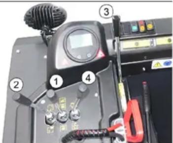

natural_image
Exterior view of a black industrial machine with yellow fan and wheels (no visible text or symbols)→ Raise the roller brush and side brushes using the control levers: Control lever 1 to middle position and control lever 3 forwards.
→ Close the container flap, in order to do so, move the control lever (4) to the back:
Note: The green indicator lamp must light up.
→ Raise the container flap, in order to do so, move the waste container control lever (2) to the back:
→ Slowly drive towards the collection container.
→ Lock parking brake.
→ Open the container flap, in order to do so, push the container flap operating lever (4) to the front and empty the waste container.
Note: The red indicator lamp must light up.
→ Close the container flap, in order to do so, push the container flap operating lever (4) to the back until it is tipped inwards in the end position.
Note: The green indicator lamp must light up.
→ Release parking brake.
→ Drive away the collection container slowly.
→ Lower the waste container into the end position, in order to do so, move the waste container control lever (2) to the front
Turn off the appliance
→ Press brake pedal and keep it depressed.
→ Lock parking brake.
→ Turn ignition key to "0" and remove it.
Transport
△DANGER
Transport damage!
→ Observe the net weight (transport weight) of the device during transport on trailers or vehicles.
→ When transporting in vehicles, secure the appliance according to the guidelines from slipping and tipping over.
→ Turn ignition key to "0" and remove it.
→ Lock parking brake.
→ Secure the appliance at the lashing points (4x) using tension belts, ropes or chains.
→ Secure the wheels of the machine with wheel chocks.
→ Disconnect the battery of the sweeper during transport.
Storage/decommissioning
△DANGER
Risk of injury and damage! Note the weight of the appliance in case of storage.
→ Park the sweeper on a level surface in a dry, frost protected area. Protect it against dust by means of covering material.
→ Raise the roller brush and the side-brushes to prevent the bristles from being damaged.
→ Close the container flap.
→ Turn ignition key to "0" and remove it.
→ Lock parking brake.
→ Lock the sweeper to ensure that it does not roll off.
Additionally observe the following points if the sweeper is not used over a longer period of time:
→ Clean the inside and outside of the sweeper.
→ Remove the battery plug from machine.
→ Charge battery and recharge it approx. every 2 months.
Care and maintenance
△CAUTION
Risk of damage due to short circuit!
→ When working on the electrical system or before opening electrical covers, the battery must be disconnected or the battery connector disconnected.
ATTENTION
Risk of damage!
→ Do not wash the fine dust filter.
→ Maintenance work may only be carried out by approved customer service outlets or experts in this field who are familiar with the respective safety regulations.
→ Mobile appliances used for commercial purposes are subject to safety inspections according to VDE 0701.
General notes
→ Park the sweeper on an even surface.
→ Turn ignition key to "0" and remove it.
→ Lock parking brake.
Cleaning
CAUTION
Risk of damage!
Do not clean the appliance with a water hose or high-pressure water jet (danger of short circuits or other damage).
Cleaning the inside of the machine
△DANGER
Risk of injury!
→ Wear dust mask and protective goggles.
→ Clean machine with a cloth.
→ Blow through machine with compressed air.
External cleaning of the appliance
→ Clean the machine with a damp cloth which has been soaked in mild detergent.
Note: Do not use aggressive cleaning agents.
Maintenance intervals
Note: The elapsed-time counter shows the timing of the maintenance intervals.
Maintenance by the customer
Note: Where maintenance is carried out by the customer, all service and maintenance work must be undertaken by a qualified specialist. If required, a specialised Kärcher dealer may be contacted at any time.
Daily maintenance:
→ Check battery charging status; charge batteries it if required (see Chapter "Charging the batteries").
→ Check the sweeping roller and the side brush for wear and wrapped belts.
→ Check the wheels for tied up belts.
→ Check function of all operator control elements.
→ Check appliance for damages.
→ Clean the dust filter with the filter cleaning button.
Weekly maintenance:
→ Check hydraulic unit.
→ Check the hydraulic oil level.
→ Check brake fluid status.
→ Check the pad for wear, replace if required.
→ Check the container lid and lubricate it.
Maintenance following wear:
→ Replace sealing strips.
→ Readjust the side seals or replace them.
→ Replace roller brush.
→ Replace side brush.
Note: For description, see section on Maintenance work.
Maintenance by Customer Service
Maintenance to be carried out after 50 operating hours:
Have the first maintenance performed by the customer service in accordance with the inspection check list.
Maintenance to be carried out after 250 operating hours:
Have the maintenance performed by the customer service in accordance with the inspection check list.
In order to safeguard warranty claims, all service and maintenance work during the warranty period must be carried out by the authorised Kärcher Customer Service in accordance with the maintenance booklet.
Maintenance Works
Preparation:
Park the sweeper on an even surface. Turn ignition key to "0" and remove it. Lock parking brake.
Securing the raised waste container ⚠️DANGER
Risk of injury! Always apply the safety bar when the waste container is raised. Perform the safeguarding only from outside the hazard zone.
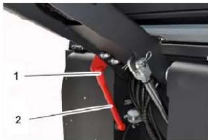
1 Holder of safety rod
2 Safety rod
Fold the safety rod for the high emptying up and insert it into the holder (secured).
Replace batteries
ATTENTION
Observe the orientation of the battery terminals when installing the batteries. Battery terminals are installed on the left in the direction of travel.
The batteries can only be exchanged as a set. The exchange has to be performed by trained personnel.
Due to the heavy weight (300 kg), the batteries must be exchanged using a crane.
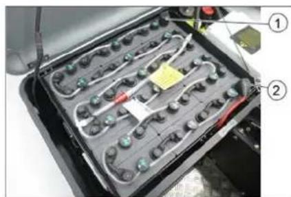
natural_image
Interior view of a battery pack with labeled components (no readable text or symbols)Battery terminals - travel direction left
1 Negative terminal
2 Positive terminal
When removing the battery, disconnect the negative terminal wire first.
Fasten the crane chains in the four eyelets of the battery set and carefully lift out the batteries.
Check hydraulic oil level and refill hydraulic oil
NOTICE
The waste container must not be raised. Open the engine hood.

1 Looking glass
2 Screw cap, oil fill opening
3 Container (without function)
Check hydraulic oil level in the looking glass.
- The oil level must lie between "MIN" and "MAX" marking.
- Add hydraulic oil if the oil level is below the "MIN" marking.
Loosen the closing cap of the oil filling opening.
Clean the filling area.
Refill hydraulic oil.
Oil grade: see Technical Data
Replace and tighten the closing cap of the oil filling opening.
Check hydraulic unit
Lock parking brake.
Start the motor.
Only the authorised customer service is permitted to carry out maintenance tasks on the hydraulic unit.
Check all hydraulic hoses and connections and ensure that they are leak-proof.
Checking roller brush
△DANGER
Risk of injury! Always apply the safety bar when the waste container is raised.
Perform the safeguarding only from outside the hazard zone.
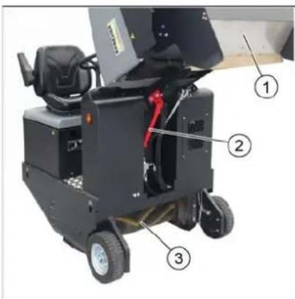
1 Waste container
2 Safety rod
3 Roller brush
Switch off device.
Lift the emptied waste container to the end position. The roller brush is visible. Secure the waste container. See chapter "Securing the raised waste container".
Turn ignition key to "0" and remove it.
Check the roller brush for damage, remove wrapped tapes or cords.
Fold the safety rod down into the receptacle (raised waste container is unsecured).
Lower the waste container up to the end-position.
Replacing roller brush
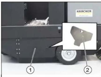
1 Side panel, right
2 Key for roller brush access
Lift the emptied waste container to the end position.
Secure the waste container. See chapter "Securing the raised waste container".
Open the side covers using a key.
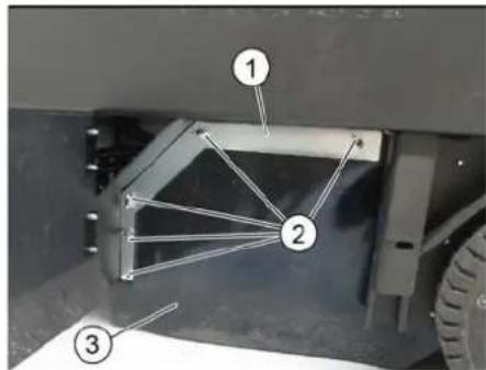
1 Holding bow
2 Wing nut
3 Side seal
Unscrew the wing nuts.
Remove the retaining clamp.
Flip the side seal out.
Uncscrew the retaining screw of the roller brush intake, and swing the intake to the outside.
Pull out roller brush.

natural_image
Abstract geometric pattern with diagonal stripes and a blue upward arrow (no text or symbols)Installation position of roller brush in direction of travel (top view)
Note: When installing the new roller brush, ensure correct positioning of the bristle assembly.
→ Install new roller brush. The nuts of the roller brush must be inserted on the notches of the opposite crank.
Note: Once the new roller brush has been installed, the sweeping track must readjusted.
Check and adjust roller brush sweeping track
Note: The sweeping track is factory-set to 80 mm; it is steplessly adjustable if the brush roller wears down.
→ Switch off suction blower.
→ Drive sweeper on to a smooth, even surface covered with a visible layer of dust or chalk.
→ Roller brush and side brush control lever (1) backwards: Switches the roller brush on.
Roller brush control lever (3) backwards: Lowers the roller brush.
→ Allow the roller brush to run for approx. 10 seconds.
→ Roller brush and side brush control lever (1) to middle position.
Roller brush control lever (3) forwards: Raises the roller brush.
→ Raise waste container.
→ Drive machine backwards.
→ Check sweeping mirror.

The sweeping track should have an even rectangular shape which is 80-85 mm wide.

natural_image
Close-up of a mechanical device with numbered components and control buttons (no readable text or symbols)→ Undo and adjust the stop screw for wear adjustment (12).
Stop screw at the top: narrow sweeping area.
Stop screw at the bottom: broad sweeping area.
→ Tighten the stop screw again.
→ Check the sweeping area of the roller brush again as described.
Check and adjust sweeping track of the side-brush
→ The side-brushes lift up.
→ Drive sweeper on to a smooth, even surface covered with a visible layer of dust or chalk.
→ Lower the side brushes using the control lever and allow them to run for approx. 10 seconds.
→ The side-brushes lift up.
→ Drive machine backwards.
→ Check sweeping mirror.
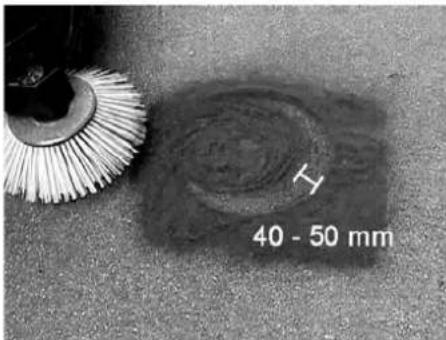
The width of the sweeping track should lie between 40-50 mm.
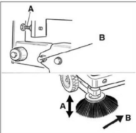
→ Set the sweeping track using the two adjusting screws.
→ Check sweeping mirror.
Adjust the side seals
△DANGER
Risk of injury! Always apply the safety bar when the waste container is raised.
→ Lift the emptied waste container to the end position.
Secure the waste container. See chapter "Securing the raised waste container".
→ Open the side cover as described in Chapter "Replace brush roller".
→ Relase the 6 wing nuts on the side holding plate.
→ Loosen 3 nuts (SW 13) on the front holding plate.
→ Press the side seal down (elongated hole) until it is about 1 to 3 mm to the floor.
→ Screw in the holding plates.
→ Repeat the procedure on the other side of the appliance.
Checking/changing the fine dust filter ⚠ WARNING
Risk of injury!
→ Wear a dust mask when working around the dust filter. Observe safety regulations on the handling of fine particles.
→ Clean the fine dust filter with the filter cleaning button.
→ Empty waste container.
→ Wear a dust mask when working around the dust filter. Observe safety regulations on the handling of fine particles. → Clean the fine dust filter with the filter cleaning button. → Empty waste container.
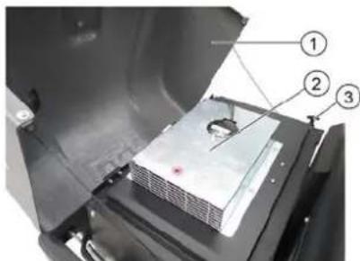
1 Cover
2 Filter cover (vibrator system)
3 Lock, filter cover (2x)
→ Fold cover forwards.
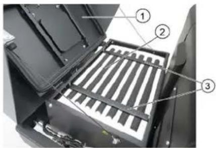
1 Cover
2 Fine dust filter
3 Cross struts
→ Open the lock.
→ Open filter cap.
→ Check the fine dust filter, clean or replace if necessary.
Note
Exchanging the fine dust filter may only be done by Kärcher Customer Service.
→ Insert and lock the filter cover.
Replacing fuses
△CAUTION
Risk of damage!
→ Make sure that the covers of the fuse boxes are not interchanged. ATTENTION
Only use fuses with identical safety ratings.
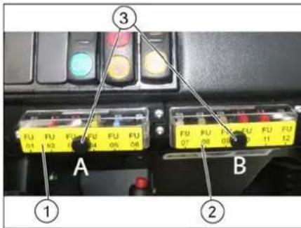
1 Fuse box A
2 Fuse box B
3 L o c k n u t
→ Unscrew the knurled nut.
→ Open the cover on the fuse box.
→ Check the fuses.
→ Replace defective fuses.
Fuse box A
| FU01 Safety relayStart up | 5 A |
| FU02 Enable DC / DC 10 A | |
| FU03 Beacon lampHorn | 10 A |
| FU04 Suction blower 20 A | |
| FU05 Vibrator system 15 A | |
| FU06 DC / DC input 20 A |
Fuse box B
| FU07 Multifunction display 5 A | |
| FU08 Reverse warning signalFlap indicator | 7.5 A |
| FU09 Safety relaySuction blowerVibrator system | 5 A |
| FU10 Water pump (option) 10 A | |
| FU11 Lighting system (optional)Blinker (option)Blue Spot (option) | 10 A |
| FU12 Shaking system flat fold filter and round filter (option) | 15 A |
Main relay fuse
| FU 13* Main relay 125 A |
* These fuses may only be changed by Customer Service, as it is necessary to check the device for potential faults.
EU Declaration of Conformity
We hereby declare that the machine described below complies with the relevant basic safety and health requirements of the EU Directives, both in its basic design and construction as well as in the version put into circulation by us. This declaration shall cease to be valid if the machine is modified without our prior approval.
Product: Ride-on vacuum sweeper
Type: KM 105/180 R Bp 1.186-050.0 KM 105/180 R Bp Pack 1.186-051.0
Relevant EU Directives
2006/42/EC (+2009/127/EC)
2014/30/EU
2000/14/EC
Applied harmonized standards
EN 60335-1
EN 60335-2-72
EN 55012: 2007 + A1: 2009
EN 61000-6-2:2005
EN 62233: 2008
Applied conformity evaluation method
2000/14/EC: Appendix V
Sound power level dB(A)
Measured: 90
Guaranteed: 93
The signatories act on behalf of and with the authority of the company management.


Documentation supervisor:
S. Reiser
Alfred Kärcher SE & Co. KG
71364 Winnenden (Germany)
Tel.: +49 7195 14-0
Fax: +49 7195 14-2212
Winnenden, 2020/01/01
Troubleshooting
| Fault Remedy | |
| Device does not drive or drives only slowly | Sit on the driver seat, the seat contact switch gets activated. |
| Have the drive motor fuse, FU 13, checked by Customer Service | |
| Charging or replacing battery | |
| Release parking brake | |
| Check for trapped ribbons and strings. | |
| Inform Kärcher Customer Service. | |
| Whistling sound in the hydraulic system | Refill hydraulic fluid |
| Inform Kärcher Customer Service. | |
| Brushes are rotating slowly or not at all | Check for trapped ribbons and strings. |
| Inform Kärcher Customer Service. | |
| Too little or no suction power in the brush area | Clean dust filter |
| Inform Kärcher Customer Service. | |
| Dust gathers in the machine Adjust | the side seals |
| Switch on blower | |
| Clean dust filter | |
| Replace filter washers | |
| Inform Kärcher Customer Service. | |
| Sweeping unit does not pick up waste | Empty waste container |
| Clean dust filter | |
| Replacing roller brush | |
| Adjust sweeping track | |
| Replace sealing strips of the waste container | |
| Remove the blocking of the brush roller | |
| Inform Kärcher Customer Service. | |
| Waste container does not raise or lower | Check the fuses. |
| Remove the locking support from the waste container | |
| Inform Kärcher Customer Service. | |
| Waste container is rotating slowly or not at all | Inform Kärcher Customer Service. |
| Operation problems with hydraulic movement parts | Inform Kärcher Customer Service. |
Technical specifications
| KM 105/180 R Bp Classic | KM 105/180 R Bp Pack Classic | ||
| Machine data | |||
| Drive speed, forward km/h 6 6 | |||
| Drive speed, reverse km/h 3 3 | |||
| Climbing capability (max.) -- 14% 14% | |||
| Surface cleaning performance without side brushes m | ^2/h 4680 4680 | ||
| Surface cleaning performance with 1 side brushes m | ^2/h 6300 6300 | ||
| Working width without side brushes mm 780 | 780 | ||
| Working width with 1 side brushes | mm 1050 1050 | ||
| Protection type, drip-proof | -- IPX 3 | IPX 3 | |
| Usage duration with battery fully charged | h | 2.5 | 2.5 |
| Electrical system | |||
| Battery capacity | V, Ah | --- | 36, 240 |
| Battery set | kg | --- | 300 |
| Hydraulic system | |||
| Hydraulic oil type | -- HV 46 | HV 46 | |
| Waste container | |||
| Max. unloading height | mm 1340 1340 | ||
| Volume of waste container | I | 180 | 180 |
| Roller brush | |||
| Roller brush diameter mm 280 280 | |||
| Roller brush width mm 780 780 | |||
| Speed 1/min 360 360 | |||
| Sweeping track mm 80 80 | |||
| Side brushes | |||
| Side brush diameter mm 580 580 | |||
| Speed 1/min 80 80 | |||
| Solid rubber tyres | |||
| Size, front -- 4.00-6 4.00-6 | |||
| Size, rear -- 300 x 145 - 6 300 x 145 - 6 | |||
| Brake | |||
| Front wheels -- mechanical mechanical | |||
| Rear wheel | -- Electrical | Electrical | |
| Filter and vacuum system | |||
| Type | -- Pocket filter | Optionally available: Flat fold filters and round filters | Pocket filterOptionally available: Flat fold filters and round filters |
| Speed 1/min 2600 2600 | |||
| Filter surface area, fine dust filter | m2 | 5.2 | 5.2 |
| Nominal vacuum, suction system | mbar | 6 | 6 |
| Nominal volume flow, suction system | m3/h | 600 600 | |
| Vibrator system | -- Electric motor | Electric motor | |
| Working conditions | |||
| Temperature °C -5 and +40 | -5 and +40 | ||
| Air humidity, non-condensing | % | 0 - 90 | 0 - 90 |
| Values determined as per EN 60335-2-72 | |||
| Noise emission | |||
| Sound pressure level LpA | dB(A) | 70 70 | |
| Uncertainty KpA | dB(A) | 3 | 3 |
| Sound power level LwA + Uncertainty KwA | dB(A) | 93 93 | |
| Machine vibrations | |||
| Hand-arm vibration value | m/s2 | 0.7 | 0.7 |
| Seat | m/s2 | 0.5 | 0.5 |
| Uncertainty K | m/s2 | 0.1 | 0.1 |
| Dimensions and weights | |||
| Length x width x height | mm 1847 x 1065 x 1388 | 1847 x 1065 x 1388 | |
| Right turning radius | mm 2470 | 2470 | |
| Left turning radius mm 2470 2470 | |||
| Unladen weight (with/ without battery) | kg | 560/860 | 560/860 |
| Permissible overall weight | kg | 1224 | 1224 |
| Permissible front axle load | kg | 734 734 | |
| Permissible rear axle load | kg | 490 490 | |
| Subject to technical modifications! | |||
www.kaercher.com/REACH
Garantie
Poids (sans batteries) 560 kg*
natural_image
Close-up of a mechanical component with labeled parts 1 and 2, showing no readable text or symbols.natural_image
Close-up of a car interior with four switches and a highlighted indicator light (no text or symbols visible)
natural_image
Exterior view of a modern office building (no signage)natural_image
Interior view of an electric vehicle battery pack with labeled components (no text or symbols visible)natural_image
Abstract geometric pattern with layered chevron shapes and a blue upward arrow (no text or symbols)natural_image
Close-up of a mechanical device with numbered components and wiring (no readable text or symbols)1 Capot
1 Capot
2006/42/CE (+2009/127/CE)
2014/30/UE
2000/14/CE
71364 Winnenden (Germany)
Tel.: +49 7195 14-0
Fax: +49 7195 14-2212
Winnenden, 2020/01/01
www.kaercher.com/REACH
Garanzia
natural_image
Close-up of a mechanical component with labeled parts 1 and 2, showing no readable text or symbols.natural_image
Close-up of a computer control panel with four buttons and a highlighted yellow button (no text or symbols visible)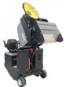
natural_image
Industrial machine with yellow fan and wheels, no visible text or symbolsnatural_image
Interior view of an electronic battery pack with labeled components (no readable text or symbols)natural_image
Abstract geometric pattern with layered triangular shapes and a blue upward arrow (no text or symbols)1 C of a n o
1 C o f a n o
2006/42/CE (+2009/127/CE)
2014/30/UE
2000/14/CE
71364 Winnenden (Germany)
Tel.: +49 7195 14-0
Fax: +49 7195 14-2212
Winnenden, 2020/01/01
www.kaercher.com/REACH
Garantie
natural_image
Close-up of a mechanical component with labeled parts 1 and 2, no readable text or symbols beyond labelsnatural_image
Close-up of a computer control panel with colored buttons and an arrow pointing to a yellow button (no text or symbols visible)
natural_image
Industrial machine with yellow fan and wheels, no visible text or symbolsnatural_image
Interior view of a battery pack with labeled components (no readable text or symbols)Batterijpolen - in rijrichting links
1 Negatieve pool
2 Positieve pool
1 Kijkglas
natural_image
Diagram of a layered structure with an upward arrow, no text or symbols present1 Apparaatkap
2 Filterafdekking (trilsysteem)
3 Sluiting, filterafdekking (2x)
1 Apparaatkap
2 Fijnstofffilter
3 Dwarsbalk
→ Sluiting openen.
→ Filterafdekking openen.
Chairman of the Board of Management
S. Reiser
Director Regulatory Affairs & Certification
71364 Winnenden (Germany)
Tel.: +49 7195 14-0
Fax: +49 7195 14-2212
Winnenden, 2020/01/01
Hulp bij storingen
www.kaercher.com/REACH
Garantía
natural_image
Close-up of a mechanical component with labeled parts 1 and 2, showing no readable text or symbols.natural_image
Close-up of a car dashboard with four colored buttons and a white arrow pointing to one (no text or symbols visible)
natural_image
Exterior view of a black industrial machine with a yellow circular top component (no visible text or symbols)natural_image
Interior view of a battery pack with labeled components (no readable text or symbols)natural_image
Abstract geometric pattern with layered diagonal stripes and a blue upward arrow (no text or symbols)1 Capó del aparato
2 filtro para polvo fino
3 Travesaños
2006/42/CE (+2009/127/CE)
2014/30/UE
2000/14/CE

Chairman of the Board of Management
S. Reiser
Director Regulatory Affairs & Certification
71364 Winnenden (Germany)
Tel.: +49 7195 14-0
Fax: +49 7195 14-2212
Winnenden, 2020/01/01
Carregar as baterias ... PT 5
www.kaercher.com/REACH
Garantia
Carregar as baterias
CUIDADO
natural_image
Close-up of a mechanical component with labeled parts 1 and 2, showing internal structure (no text or symbols beyond labels)1 Alavanca de comando da escova cilindrica de varredura e vassoura lateral
2 Alavanca de comando do colector do lixo varrido
3 Alavanca de comando da escova cilíndrica de varredura
4 Alavanca de comando da tampa do recipiente
Alavanca de comando da escova cilíndrica de varredura e vassoura lateral
→ Alavanca de comando (1) para a frente: Escova cilíndrica de varredura ligada, baixar a vassoura lateral e ligar.
→ Alavanca de comando (1) para trás: Escova cilíndrica de varredura ligada.
Alavanca de comando do colector do lixo varrido
natural_image
Close-up of a car interior control panel with four colored buttons and an arrow pointing to one (no visible text or symbols)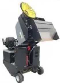
natural_image
Industrial machine with yellow fan and wheels (no visible text or symbols)natural_image
Interior view of an electric vehicle battery pack with labeled components (no text or symbols visible)1 Recipiente de material varrido
natural_image
Diagram of a layered structure with a blue upward arrow at the base (no text or symbols)1 Tampa da máquina
2 Tampa do filtro (sistema vibrador)
3 Fecho, cobertura do filtro (2x)
1 Tampa da máquina
2 Filtro de poeiras finas
3 Travessas
→ Abrir o fecho.
2006/42/CE (+2009/127/CE)
2014/30/UE
2000/14/CE
H. Jenner Chairman of the Board of Management
S. Reiser Director Regulatory Affairs & Certification
71364 Winnenden (Germany)
Tel.: +49 7195 14-0
Fax: +49 7195 14-2212
Winnenden, 2020/01/01
www.kaercher.com/REACH
Garanti
natural_image
Close-up of a mechanical component with labeled parts 1 and 2, no readable text or symbols beyond labelsnatural_image
Close-up of a car interior control panel with colored buttons and an arrow pointing to one (no visible text or symbols)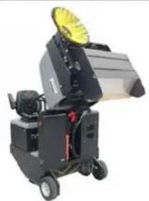
natural_image
Exterior view of a black industrial machine with yellow circular top and wheels (no visible text or symbols)natural_image
Interior view of an electric vehicle battery pack with labeled components (no text or symbols visible)1 Smudsbeholder
2 Sikringsstang
3 Fejevalse
1 Holdebøjle
2 Vingemøtrik
3 Tætning i siden
natural_image
Abstract geometric pattern with diagonal stripes and a blue upward arrow (no text or symbols)1 S k æ r m
2 Fintstøvfilter
3 Tværdragere
2006/42/EF (+2009/127/EF)
2014/30/EU
2000/14/EF

Chairman of the Board of Management
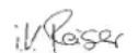
S. Reiser
Director Regulatory Affairs & Certification
71364 Winnenden (Germany)
Tel.: +49 7195 14-0
Fax: +49 7195 14-2212
Winnenden, 2020/01/01
Hjælp ved fejl
Feilretting....NO 11
Tekniske data ..... NO 11
www.kaercher.com/REACH
Garanti
natural_image
Close-up of a mechanical component with labeled parts 1 and 2, no readable text or symbols beyond labels1 Hendel setejustering
2 F ø r e r s e t e
natural_image
Close-up of a car interior control panel with colored buttons and an arrow pointing to one (no visible text or symbols)
natural_image
Exterior view of a black industrial machine with a yellow fan and wheels (no visible text or symbols)→ Løfte feievals og sidekost med betjenningsspakene: Betjeningsspak 1 i midten og betjeningsspak 3 forover.
→ Lukk beholderklaffen, dertil trekkes betjeningsspaken (4) bakover.
natural_image
Interior view of a battery pack with labeled components (no readable text or symbols)1 Seglass
1 Feieavfallsbeholder
2 Sikringsstang
3 Feievalse
1 Holdebøyle
2 Vingemutter
natural_image
Diagram of a layered structure with a blue upward arrow at the base (no text or symbols)1 Maskinhette
2 Filterdeksel (vibrasjonssystem)
3 Lås, filterdeksel (2x)
→ Vipp maskinhetten forover.
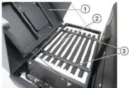
2006/42/EF (+2009/127/EF)
2014/30/EU
2000/14/EF
2000/14/EF: Vedlegg V
Lydeffektnivå dB(A)
Målt: 90
Garantert: 93

Chairman of the Board of Management
S. Reiser
Director Regulatory Affairs & Certification
71364 Winnenden (Germany)
Tel.: +49 7195 14-0
Fax: +49 7195 14-2212
Winnenden, 2020/01/01
Feilretting
www.kaercher.com/REACH
Garanti
natural_image
Close-up of a mechanical component with labeled parts 1 and 2, no readable text or symbols beyond labelsnatural_image
Close-up of a car interior control panel with colored buttons and an arrow pointing to one (no visible text or symbols)→ Starta fläkt.
→ Vid ytrengöring
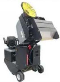
natural_image
Exterior view of a black industrial machine with a yellow fan and wheels (no visible text or symbols)natural_image
Interior view of a battery pack with labeled components (no readable text or symbols)1 Sopbehållare
2 Säkringsstång
3 Borstvals
1 Hållarbygel
2 Vingmutter
3 Tätning på sidan
natural_image
Abstract geometric pattern with diagonal stripes and a blue upward arrow (no text or symbols)
Chairman of the Board of Management

S. Reiser
Director Regulatory Affairs & Certification
71364 Winnenden (Germany)
Tel.: +49 7195 14-0
Fax: +49 7195 14-2212
Winnenden, 2020/01/01
www.kaercher.com/REACH
Takuu
natural_image
Close-up of a mechanical component with labeled parts 1 and 2, showing no readable text or symbols.natural_image
Close-up of a car interior control panel with colored buttons and an arrow pointing to the next button (no visible text or symbols)
natural_image
Exterior view of a black industrial machine with a yellow fan and wheels (no visible text or symbols)natural_image
Interior view of a battery pack with labeled components (no readable text or symbols)1 Roskasäiliö
2 Varmistustanko
3 Lakaisutela
natural_image
Diagram of a layered structure with a blue upward arrow, no text or symbols presentnatural_image
Close-up of mechanical components with numbered annotations (3 and 12), no readable text or symbols present.
Chairman of the Board of Management

S. Reiser
Director Regulatory Affairs & Certification
71364 Winnenden (Germany)
Tel.: +49 7195 14-0
Fax: +49 7195 14-2212
Winnenden, 2020/01/01
Häiriöapu
natural_image
Close-up of a mechanical component with labeled parts 1 and 2, showing internal structure (no text or symbols beyond labels)natural_image
Close-up of a car interior control panel with colored buttons and an arrow pointing to a yellow button (no text or symbols visible)
natural_image
Exterior view of a black industrial machine with yellow circular top component (no visible text or symbols)natural_image
Interior view of a battery pack with labeled components (no readable text or symbols)1 Y α λ ο δ ε í κ τ η ζ
natural_image
Abstract geometric pattern with layered chevron shapes and a blue upward arrow (no text or symbols)1 Κάλυμμα μηχανής
Chairman of the Board of Management
S. Reiser
Director Regulatory Affairs & Certification
71364 Winnenden (Germany)
Tel.: +49 7195 14-0
Fax: +49 7195 14-2212
Winnenden, 2020/01/01
Αντιμετώπιση βλαβών
www.kaercher.com/REACH
Garanti
natural_image
Close-up of a mechanical component with labeled parts 1 and 2, showing no readable text or symbols.1 Koltuk ayarlama kolu
2 Sürücü koltuğu
natural_image
Close-up of a car interior control panel with colored buttons and an arrow pointing to one (no visible text or symbols)
natural_image
Industrial machine with large fan and wheels, no visible text or symbolsnatural_image
Interior view of an electric vehicle battery pack with labeled components (no text or symbols visible)1 Tutma kolu
2 Kanatlı somun
3 Yan conta
natural_image
Abstract geometric pattern with layered chevron shapes and a blue upward arrow (no text or symbols)1 Cihaz kapağı
2 Ince toz filtresi
3 Çapraz kiriş
→ Kilidi açın.

Chairman of the Board of Management

Director Regulatory Affairs & Certification
71364 Winnenden (Germany)
Tel.: +49 7195 14-0
Fax: +49 7195 14-2212
Winnenden, 2020/01/01
Arizalarda yardım
www.kaercher.com/REACH
Гарантия
natural_image
Close-up of a mechanical component with labeled parts 1 and 2, showing no readable text or symbols beyond labels.natural_image
Close-up of a car interior control panel with colored buttons and an arrow pointing to one (no visible text or symbols)
natural_image
Exterior view of a black industrial machine with a yellow circular top component (no visible text or symbols)natural_image
Interior view of a battery pack with visible circuitry and components (no text or symbols)1 Смотровое стекло
1 С к о б а
2 Барашковая гайка
natural_image
Diagram of a layered structure with a blue upward arrow, no text or symbols present
Chairman of the Board of Management

S. Reiser
Director Regulatory Affairs & Certification
71364 Winnenden (Germany)
Tel.: +49 7195 14-0
Fax: +49 7195 14-2212
Winnenden, 2020/01/01
www.kaercher.com/REACH
Garancia
natural_image
Close-up of a mechanical component with labeled parts 1 and 2, showing no readable text or symbols.natural_image
Close-up of a car interior control panel with indicator lights and a white arrow pointing to the next button (no visible text or symbols)
natural_image
Exterior view of a black industrial machine with yellow fan and wheels (no visible text or symbols)natural_image
Interior view of a battery pack with labeled components (no text or symbols visible)natural_image
Diagram of a layered structure with an upward arrow, no text or symbols presentnatural_image
Close-up of a mechanical device with numbered components and a warning label (no readable text or symbols)
Chairman of the Board of Management

S. Reiser
Director Regulatory Affairs & Certification
71364 Winnenden (Germany)
Tel.: +49 7195 14-0
Fax: +49 7195 14-2212
Winnenden, 2020/01/01
www.kaercher.com/REACH
Záruka

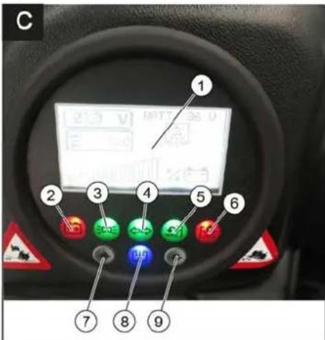
natural_image
Close-up of a mechanical component with labeled parts 1 and 2, showing no readable text or symbols.natural_image
Close-up of a car interior panel with colored buttons and a white arrow pointing to one (no visible text or symbols)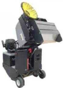
natural_image
Exterior view of a black industrial machine with yellow fan and wheels (no visible text or symbols)natural_image
Interior view of an electronic battery pack with labeled components (no readable text or symbols)1 O k é n k o
natural_image
Diagram of a layered structure with a blue upward arrow, no text or symbols present2006/42/ES (+2009/127/ES)
2014/30/EU
2000/14/ES

Chairman of the Board of Management
Director Regulatory Affairs & Certification
71364 Winnenden (Germany)
Tel.: +49 7195 14-0
Fax: +49 7195 14-2212
Winnenden, 2020/01/01
Pomoc při poruchách
www.kaercher.com/REACH
Garancija
natural_image
Close-up of a mechanical component with labeled parts 1 and 2, showing internal structure (no text or symbols beyond labels)natural_image
Close-up of a car interior with illuminated buttons and a white arrow pointing to one (no text or symbols visible)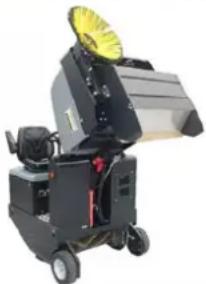
natural_image
Industrial machine with yellow fan and wheels (no visible text or symbols)natural_image
Interior view of a battery pack with labeled components (no text or symbols visible)Pola akumulatorja – na levi strani v smeri vožnje
1 M i n u s p o l
2 Plus pol
→ Pri demontiranju baterije je treba paziti na to, da se najprej odklopi vodnik minus pola.
→ Žico žerjava pritrdite na 4 rinke kompleta baterij in previdno dvignite baterije.
1 Zbiralnik smeti
2 Varnostni drog
3 Pometalni valj
1 Držalna palica
2 Krilata matica
3 Stransko tesnilo
→ Odvijte krilate matice.
→ Snemite držalno palico.
→ Stransko tesnilo sklopite navzven.
→ Izvijte pritrditveni vijak nosilca pometal-nega valja in nosilec zasukajte nav-zven.
→ Izvlecite pometalni valj
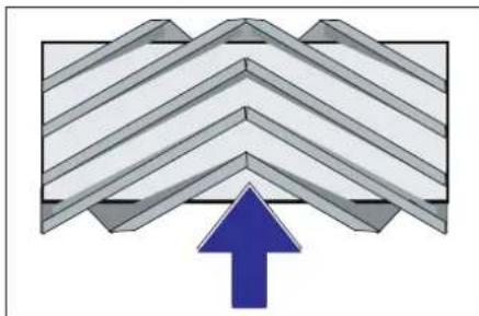
natural_image
Diagram of a layered structure with a blue upward arrow at the base (no text or symbols)Vgradni položaj pometalnega valja v smeri vožnje (tloris)
Opozorilo: Pri vgradnji novega pometalne-ga valja pazite na položaj krtačnega na-stavka.
→ Vstavite nov pometalni valj. Zareze po-metalnega valja morajo biti nataknjene na utore nasproti ležeče nihalke.
Opozorilo: Po vgradnji novega pometalne-ga valja je potrebno površino pometanja na novo nastaviti.
Preverjanje in nastavljanje površine pometanja pometalnega valja
Opozorilo: Pometalna površina je tovarniško nastavljena na 80 mm, ob obrabi po-metalnih valjev jo je mogoče brezstopenjsko nastaviti.
→ Odprite in nastavite omejevalni vijak za ponovno nastavitev obrabe (12).
Potisnite navzgor: ožja površina pometanja.
Potisnite navzdol: širša površina pometanja.
→ Ponovno privijte omejevalni vijak.
1 Pokrov naprave
2 Pokrov filtra (sistem tresenja)
3 Zapiralo, pokrov filtra (2x)
→ Pokrov stroja sklopite naprej.
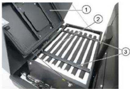
1 Pokrov naprave
2 Filter za droben prah
3 Prečne opore
→ Odprite zapiralo.
→ Odprite pokrov filtra.
→ Preverite filter za fini prah, po potrebi ga očistite ali zamenjajte.
Napotek
Filter za fini prah sme zamenjati samo servisna služba podjetja Kärcher.
→ Namestite pokrov filtra in ga blokirajte.
Menjava varovalk
PREVIDNOST
Nevarnost poškodb!
2006/42/ES (+2009/127/ES)
2014/30/EU
2000/14/ES
H. Jenner Chairman of the Board of Management
S. Reiser Director Regulatory Affairs & Certification
71364 Winnenden (Germany)
Tel.: +49 7195 14-0
Fax: +49 7195 14-2212
Winnenden, 2020/01/01
Pomoč pri motnjah
www.kaercher.com/REACH
Gwarancja
natural_image
Close-up of a mechanical component with labeled parts 1 and 2, showing no readable text or symbols.natural_image
Close-up of a car interior control panel with four buttons and a highlighted indicator (no text or symbols visible)
natural_image
Exterior view of a modern office building (no signage)natural_image
Interior view of a battery pack with labeled components (no text or symbols visible)1 Wziernik
1 Zbiornik śmieci
1 Strzemiączko
natural_image
Abstract geometric pattern with layered chevron shapes and a blue upward arrow (no text or symbols)2006/42/WE (+2009/127/WE)
2014/30/UE
2000/14/WE

Chairman of the Board of Management
Director Regulatory Affairs & Certification
71364 Winnenden (Germany)
Tel.: +49 7195 14-0
Fax: +49 7195 14-2212
Winnenden, 2020/01/01
Usuwanie usterek
www.kaercher.com/REACH
Garantie
natural_image
Close-up of a mechanical component with labeled parts 1 and 2, showing no readable text or symbols.natural_image
Close-up of a car dashboard with four switches and a highlighted arrow pointing to one (no visible text or symbols)
natural_image
Exterior view of a black industrial machine with yellow fan and wheels (no visible text or symbols)natural_image
Interior view of an electric vehicle battery pack with visible circuitry and wiring (no text or symbols)1 V i z o r
1 Colier
2 Piuliță fluture
natural_image
Abstract geometric pattern with layered chevron shapes and a blue upward arrow (no text or symbols)Directive UE respectate:
2006/42/CE (+2009/127/CE)
2014/30/UE
2000/14/CE
Norme armonizate utilize:
EN 60335-1
EN 60335-2-72
EN 55012: 2007 + A1: 2009
EN 61000-6-2: 2005
EN 62233: 2008
71364 Winnenden (Germany)
Tel.: +49 7195 14-0
Fax: +49 7195 14-2212
Winnenden, 2020/01/01
natural_image
Close-up of a mechanical component with labeled parts 1 and 2, showing no readable text or symbols.1 Páka prestavenia sedadla
2 Sedadlo vodiča
→ Páku prestavenia sedadla vytiahnite smerom von.
→ Posuňte sedadlo, uvoľnite páku a ne-
chajte ju zapadnút na svoje miesto.
→ Pohybmi sedadla dopredu a dozadu skontrolujte, či je aretované.
Spustenie stroja
natural_image
Close-up of a car interior control panel with four buttons and a white arrow pointing to one (no text or symbols visible)→ Zapnút dúchadlá.

natural_image
Industrial machine with yellow fan and wheels, no visible text or symbolsnatural_image
Interior view of an automotive battery pack with labeled components (no text or symbols visible)Póly batérie - v smere jazdy vl'avo
1 Mínusový pól
2 Plusový pól
1 P r i e z o r
2 Uzatvárací kryt, plniaci otvor oleja
1 Upevňovací strmeň
2 Krídlová matica
3 Bočné tesnenie
natural_image
Diagram of a layered structure with an upward arrow, no text or symbols present1 Kryt prístroja
2 Filter na jemný prach
3 Priečka
2006/42/ES (+2009/127/ES)
2014/30/EÚ
2000/14/ES
Uplatňované harmonizované normy:
EN 60335-1
EN 60335-2-72
EN 55012: 2007 + A1: 2009
EN 61000-6-2: 2005
EN 62233: 2008

Chairman of the Board of Management
S. Reiser
Director Regulatory Affairs & Certification
71364 Winnenden (Germany)
Tel.: +49 7195 14-0
Fax: +49 7195 14-2212
Winnenden, 2020/01/01
Pomoc pri poruchách
www.kaercher.com/REACH
Jamstvo
natural_image
Close-up of a mechanical component with labeled parts 1 and 2, no readable text or symbols beyond labels1 Poluga za namještanje sjedala
2 Sjedalo vozača
natural_image
Close-up of a car interior control panel with four colored buttons and an arrow pointing to one (no visible text or symbols)→ Uključite ventilator.
→ Prilikom površinskog čišćenja:

natural_image
Exterior view of a black industrial machine with yellow fan and wheels (no visible text or symbols)→ Podignite valjak za metenje i bočnu metlu upravljačkim polugama: Upravljačka poluga 1 u sredinu i upravljačka poluga 3 prema naprijed.
→ Zatvorite poklopac spremnika pomicanjem upravljačke poluge (4) unatrag.
Napomena: Zelena prikazna lampica mora svijetliti.
→ Podignite spremnik nakupljene prljavštine pomicanjem upravljačke poluge (2) unatrag.
→ Polako dovezite uređaj do sabirne posude.
→ Zakočite pozicijsku kočnicu.
→ Otvorite poklopac spremnika tako što ćete upravljačku polugu (4) pritisnuti unaprijed i ispraznite spremnik nakupljene prljavštine.
Napomena: Crvena prikazna lampica mora svijetliti.
→ Zatvorite poklopac spremnika tako što ćete upravljačku polugu (4) povući unatrag tako da se zakrene u krajnji položaj.
Napomena: Zelena prikazna lampica mora svijetliti.
→ Otpustite pozicijsku kočnicu.
→ Polako udaljite uređaj od sabirne posu-
de.
→ Spustite spremnik nakupljene prljavštine u krajnji položaj pomicanjem upravljačke poluge (2) unaprijed.
1 Držač sigurnosne šipke
2 Sigurnosna šipka
→ Sigurnosnu šipku za visoko pražnjenje preklopite prema gore i utaknite u držač (time ste je fiksirali).
Zamjena akumulatora
PAŽNJA
natural_image
Interior view of a battery pack with labeled components (no readable text or symbols)1 Kontrolno okno
1 Spremnik nakupljene prljavštine
2 Sigurnosna šipka
3 Valjak za metenje
→ Isključite uređaj.
→ Podignite spremnik skupljene prljavšti ne do krajnjeg položaja. Postaje vidljiv valjak za metenje.
Osigurajte spremnik skupljene prljavštine. Pogledajte poglavlje „Osiguravanje podignutog spremnika nakupljene prljavštine”.
→ Kontaktni ključ okrenite u položaj "0" i izvucite ključ.
→ Ispitajte valjak za metenje u pogledu oštećenja i uklonite namotane trake ili uzice.
→ Preklopite sigurnosnu šipku prema dolje u prihvat (podignuti spremnik skupljene prljavštine je neosiguran).
→ Spustite spremnik za prljavštinu u kraj-nji položaj.
1 Pričvrsni luk
2 Leptir matica
3 Bočna brtva
→ Odvijte leptir matice.
→ Skinite pričvrsni luk.
→ Bočnu brtvu preklopite prema van.
→ Odvijte pričvrsni vijak prihvatnika valjka za metenje pa zakrenite prihvatnik prema van.
→ Izvadite valjak za metenje.
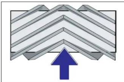
natural_image
Diagram of a layered structure with a blue upward arrow, no text or symbols present→ Odvrnite vijak graničnika za naknadno namještanje istrošenosti (12) i namje- stite ga.
1 Poklopac uređaja
2 Pokrov filtra (sustav vibratora)
3 Zatvarač, poklopac filtra (2x)
→ Preklopite poklopac uređaja prema naprijed.
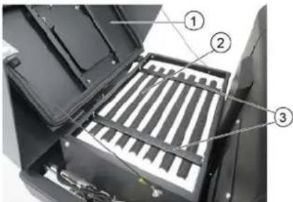
1 Poklopac uređaja
2 Filtar za finu prašinu
3 Poprečni držač
→ Otvorite zatvarač.
→ Otvorite poklopac filtra.
→ Provjerite filtar za finu prašinu, po potrebi ga očistite ili zamijenite.
Napomena
2006/42/EZ (+2009/127/EZ)
2014/30/EU
2000/14/EZ
Primijenjene uskladene norme:
EN 60335-1
EN 60335-2-72
EN 55012: 2007 + A1: 2009
EN 61000-6-2: 2005
EN 62233: 2008
H. Jenner Chairman of the Board of Management
S. Reiser Director Regulatory Affairs & Certification
Opunomoćeni za izradu dokumentacije: S. Reiser
Alfred Kärcher SE & Co. KG
71364 Winnenden (Germany)
Tel.: +49 7195 14-0
Fax: +49 7195 14-2212
Winnenden, 2020/01/01
Otklanjanje smetnji
www.kaercher.com/REACH
Garancija
U svakoj zemlji važe garantni uslovi koje je izdala naša nadležna distributivna organizacija. Eventualne smetnje na uređaju za vreme trajanja garancije uklanjamo besplatno, ukoliko je uzrok greška u materijalu ili proizvodnji. U slučaju koji podleže garanciji obratite se sa potvrdom o kupovini Vašem prodavcu ili najbližoj ovlašćenoj servisnoj službi.
Pribor i rezervni delovi
⚠ OPASNOST
U cilju sprečavanja opasnosti, popravke i ugradnju rezervnih delova sme izvoditi samo ovlašćena servisna služba.
natural_image
Close-up of a mechanical component with labeled parts 1 and 2, showing internal structure (no text or symbols beyond labels)1 Poluga za rukovanje valjkom za metenje i bočnom metlom
2 Upravljačka poluga posude za nakupljenu prljavštinu
3 Poluga za rukovanje valjkom za metenje
4 Upravljačka poluga poklopca posude
Poluga za rukovanje valjkom za metenje i bočnom metlom
natural_image
Close-up of a computer control panel with colored buttons and an arrow pointing to the next button (no visible text or symbols)→ Uključite ventilatore.
→ Prilikom površinskog čišćenja:
Poluga za rukovanje valjkom za metenje i bočnom metlom (1) prema nazad: valjak za metenje uključen. Poluga za rukovanje valjkom za metenje (3) prema nazad: valjak za metenje se spušta.
→ Upravljačka poluga poklopca posude (4) unapred: Poklopac posude se otvara.
Napomena: Zelena signalna lampica mora da svetli.
→ Prilikom čišćenja bočnih ivica:
Poluga za rukovanje valjkom za metenje i bočnom metlom (1) prema napred: valjak za metenje uključen, bočna metla uključena i spušta se. Poluga za rukovanje valjkom za metenje (3) prema nazad: valjak za metenje se spušta.
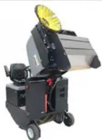
natural_image
Exterior view of a black industrial machine with yellow fan and wheels (no visible text or symbols)→ Podignuti valjak za metenje i bočnu metlu pomoću poluga za rukovanje: Poluga za rukovanje 1 na sredinu, a poluga za rukovanje 3 prema napred.
→ Da zatvorite poklopac posude upravljačku polugu (4) pomerite unazad.
Napomena: Zelena signalna lampica mora da svetli.
→ Da podignete posudu za nakupljenu prljavštinu upravljačku polugu (2) pomerite unazad.
→ Polako navezite uređaj do sabirne posude.
1 Držač sigurnosne poluge
2 Sigurnosna poluga
→ Sigurnosnu polugu za visoko pražnjenje preklopite prema gore i utaknite u držač (time ste je fiksirali).
Zamena akumulatora
PAŽNJA
Prilikom ugradnje baterija, obratiti pažnju na usmerenost polova baterije. Ugradnja polova sa leve strane u smeru kretanja. Akumulatori se menjaju samo u paru. Zamenu smeju vršiti samo kvalifikovani stručnjaci.
natural_image
Interior view of an electric vehicle battery pack with visible circuitry and wiring (no text or symbols)Polovi baterije - sa leve strane u smeru vožnje
1 Minus pol
2 Plus pol
→ Prilikom demontiranja akumulatora pazite na to da se prvo odvoji kabl sa minus pola.
→ Uže krana pričvrstite na 4 ušice kompletnog akumulatorskog seta pa pažljivo izvadite akumulatore.
Provera i dolivanje hidrauličkog ulja SAVET
Posuda za prljavštinu ne sme da bude podignuta.
→ Otvorite poklopac motora.
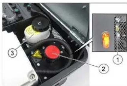
1 Kontrolno okno
2 Poklopac otvora za ulivanje ulja
3 Posuda (bez funkcije)
→ Na kontrolnom oknu proverite nivo hidrauličkog ulja.
– Nivo ulja mora da se nalazi između oznaka "MIN" i "MAX".
– Ako je nivo opao ispod oznake "MIN", treba dopuniti hidrauličko ulje.
→ Odvijte poklopac otvora za ulivanje ulja.
→ Očistite prostor za punjenje.
→ Dopunite hidrauličko ulje.
Za vrstu ulja pogledajte tehničke podatke
→ Zavijte poklopac otvora za ulivanje ulja.
Provera hidrauličkog sklopa
→ Zakočite pozicionu kočnicu.
→ Pokrenite motor.
Održavanje hidrauličke instalacije isključivo preko ovlašćene servisne službe.
→ Proverite zaptivenost svih hidrauličkih creva i priključaka.
Provera valjka za metenje
△OPASNOST
Opasnost od povreda! Uvek postavite sigurnosnu polugu kada je posuda za nakupljenu prljavštinu podignuta.
1 Posuda za nakupljenu prljavštinu
2 Sigurnosna poluga
3 Valjak za metenje
→ Isključiti uređaj.
→ Ispražnjenu posudu za nakupljenu prljavštinu podižite do krajnjeg položaja. Valjak za metenje postaje vidljiv.
Osigurajte posudu za nakupljenu prljavštinu. Pogledajte poglavlje „Obezbeđenje podignute posude za nakupljenu prljavštinu“.
→ Kontaktni ključ okrenite u položaj "0" i izvucite ključ.
→ Proverite da li ima oštećenja na valjku za metenje, uklonite zamotane trake ili vrpce.
→ Sigurnosnu polugu sklopite nadole u prihvatnik (podignuta posuda za nakupljenu prljavštinu nije zaštićena).
→ Spustite posudu za prljavštinu u krajnji položaj.
Zamena valjka za metenje
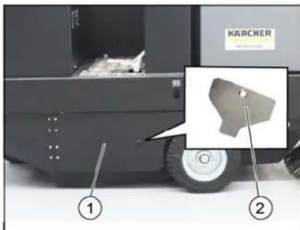
1 Bočna oplata, desno
2 Ključ za pristup valjku za metenje
→ Ispražnjenu posudu za nakupljenu prljavštinu podižite do krajnjeg položaja.
Osigurajte posudu za nakupljenu prljavštinu. Pogledajte poglavlje „Obezbeđenje podignute posude za nakupljenu prljavštinu“.
1 Kuka za držanje
2 Leptir navrtka
3 Bočna zaptivka
→ Odvijte leptir navrtke.
→ Skinite kuku za držanje.
→ Bočnu zaptivku preklopite prema spolja.
→ Odvijte pričvrsni zavrtanj prihvatnika valjka za metenje pa zakrenite prihvatnik prema spolja.
→ Izvadite valjak za metenje.
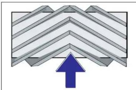
natural_image
Diagram of a layered structure with a blue upward arrow, no text or symbols presentPoložaj ugradnje valjka za metenje u smeru vožnje (pogled odozgo)
Napomena: Pri ugradnji novog valjka za metenje pazite na položaj garniture čekinja.
→ Ugradite novi valjak za metenje. Žlebovi valjaka za metenje moraju biti nataknuti na ispuste naspramnih držača.
Napomena: Nakon ugradnje novog valjka za metenje mora se iznova podesiti profil metenja.
Provera i podešavanje profila metenja valjka za metenje
Napomena: Profil metenja je fabrički podešen na 80 mm, a u slučaju istrošenosti valjka za metenje se može kontinualno podesiti.
→ Isključite usisni ventilator.
→ Uređaj za metenje odvezite na ravnu i glatku površinu koja je vidljivo prekrivena prašinom ili izmrvljenom kredom.
→ Poluga za rukovanje valjkom za metenje i bočnom metlom (1) prema nazad: valjak za metenje uključen. Poluga za rukovanje valjkom za metenje (3) prema nazad: valjak za metenje se spušta.
→ Valjak za metenje ostaviti da radi na oko 10 sekundi.
→ Poluga za rukovanje valjkom za metenje i bočnom metlom (1) na sredini.
Poluga za rukovanje valjkom za metenje (3) prema napred: valjak za metenje se podiže.
→ Odignite posudu za nakupljenu prljavštinu.
→ Pomerite uređaj vozeći ga unazad.
→ Proverite profil metenja.
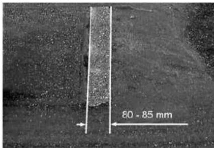
Pometena površina treba da ima oblik pravilnog pravougaonika širine između 80 i 85 mm.
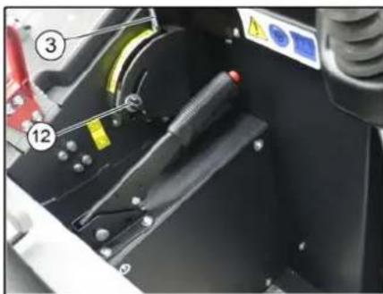
natural_image
Close-up of a mechanical assembly with numbered components (12 and 3), no visible text or symbols→ Otvoriti i podesiti granični zavrtanj naknadnog podešavanja habanja (12). Graničnik prema gore: uži profil metenja.
Graničnik prema dole: širi profil metenja.
→ Ponovo čvrsto pritegnuti granični zavrtanj.
→ Ponovo proveriti profil metenja valjka za metenje kao što je već opisano.
Provera i podešavanje profila metenja bočne metle
→ Podignite bočnu metlu.
→ Uređaj za metenje odvezite na ravnu i glatku površinu koja je vidljivo prekrivena prašinom ili izmrvljenom kredom.
→ Bočnu metlu sa polugom za rukovanje spustiti i ostaviti da radi oko 10 sekundi.
→ Podignite bočnu metlu.
→ Pomerite uređaj vozeći ga unazad.
→ Proverite profil metenja.
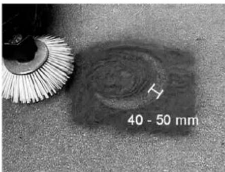
1 Poklopac uređaja
2 Poklopac filtera (sistem vibratora)
3 Zatvarač, poklopac filtera (2x)
1 Poklopac uređaja
2 Filter za finu prašinu
3 Poprečni držač
→ Otvorite zatvarač.
→ Otvorite poklopac filtera.
→ Proverite filter za finu prašinu i po potrebi ga očistite ili zamenite.
Napomena
Zamenu filtera za finu prašinu sme da vrši isključivo Kärcher servisna služba.
→ Postavite i pričvrstite poklopac filtera.
Zamena osigurača
△OPREZ
Opasnost od oštećenja!
→ Obratite pažnju da poklopci kutija sa osiguračima ne budu postavljeni obrnuto.
PAŽNJA
2006/42/EZ (+2009/127/EZ)
2014/30/EU
2000/14/EZ
Primenjene uskladene norme:
EN 60335-1
EN 60335-2-72
EN 55012: 2007 + A1: 2009
EN 61000-6-2: 2005
EN 62233: 2008
71364 Winnenden (Germany)
Tel.: +49 7195 14-0
Fax: +49 7195 14-2212
Winnenden, 2020/01/01
Otklanjanje smetnji
| Smetnja Otklanjanje | |
| Uređaj se ne kreće ili vozi sasvim polako. | Sedite na sedište vozača, kontaktni prekidača sedišta vozača se aktivira. |
| Osigurač voznog motora FU 13 treba da proveri servisna služba | |
| Punjenje ili zamena akumulatora | |
| Otkočite pozicionu kočnicu | |
| Proverite da nema upletenih traka ili petlji. | |
| Obavestite Kärcher servisnu službu. | |
| Pišteći zvuk u hidraulici Sipajte hidrauličku tečnost | |
| Četke se vrte polako ili se uopšte ne vrte | Proverite da nema upletenih traka ili petlji. |
| Obavestite Kärcher servisnu službu. | |
| U prostoru četki je usisna snaga mala ili je uopšte nema | Očistite filter za prašinu |
| Obavestite Kärcher servisnu službu. | |
| Uređaj diže prašinu Podešavanje bočnih zaptivki | |
| Jedinica za čišćenje ostavlja prljavštinu da leži | Ispraznite posudu za nakupljenu prljavštinu |
| Očistite filter za prašinu | |
| Zamenite valjak za metenje. | |
| Naknadno podesite profil metenja | |
| Zamenite zaptivne trake na posudi za prljavštinu | |
| Uklonite strana tela koja blokiraju valjak za metenje | |
| Obavestite Kärcher servisnu službu. | |
| Posuda za prljavštinu ne može da se podigne ili spusti | Proverite osigurače. |
| Ukloniti saigurnosni podupirač sa posude za nakupljenu prljavštinu | |
| Obavestite Kärcher servisnu službu. | |
| Posuda za prljavštinu se vrti presporo ili se uopšte ne vrti | Obavestite Kärcher servisnu službu. |
| Smetnje u radu s hidrauličkim pokretnim delovima | Obavestite Kärcher servisnu službu. |
Tehnički podaci
| KM 105/180 R Bp Classic | KM 105/180 R Bp Pack Classic | ||
| Podaci uređaja | |||
| Brzina vožnje prema napred km/h 6 6 | |||
| Brzina vožnje unazad km/h 3 3 | |||
| Savladavanje uspona (maks.) -- 14% 14% | |||
| Površinski učinak bez bočnih metli m | ^2/h 4680 4680 | ||
| Površinski učinak sa 1 bočnom metlom m | ^2/h 6300 6300 | ||
| Radna širina bez bočne metle | mm | 780 | 780 |
| Radna širina sa 1 bočnom metlom | mm | 1050 1050 | |
| Stepen zaštite, zaštićeno od kapajuće vode | -- | IPX 3 | IPX 3 |
| Trajanje primene pri napunjenom akumulatoru h | 2,5 | 2,5 | |
| Električne komponente | |||
| Kapacitet akumulatora | V, Ah | --- | 36, 240 |
| Akumulatorski set | kg | --- | 300 |
| Hidrauličke komponente | |||
| Tip hidrauličkog ulja | -- HV 46 | HV 46 | |
| Posuda za nakupljenu prljavštinu | |||
| Maksimalna visina pražnjenja mm 1340 1340 | |||
| Zapremina posude za prljavštinu | I | 180 | 180 |
| Valjak za metenje | |||
| Prečnik valjka za metenje mm 280 280 | |||
| Širina valjka za metenje mm 780 780 | |||
| Broj obrtaja 1/min 360 360 | |||
| Profil metenja mm 80 80 | |||
| Bočna metla | |||
| Prečnik bočnih metli mm 580 580 | |||
| Broj obrtaja 1/min 80 80 | |||
| Pneumatici od pune gume | |||
| Veličina napred -- 4.00-6 4.00-6 | |||
| Veličina pozadi -- 300 x 145 - 6 300 x 145 - 6 | |||
| Kočnica | |||
| Prednji točkovi -- mehanička mehanička | |||
| Zadnji točak | -- Električno | Električno | |
| Filterski i usisni sistem | |||
| Tip | -- Vrećasti filter | Vrećasti filter | |
| Opciono dostupno: Pljosnati naborani filter i okrugli filter | |||
| Broj obrtaja 1/min 2600 2600 | |||
| Površina filtera za finu prašinu | m2 | 5,2 | 5,2 |
| Nominalni podpritisak usisnog sistema | mbar | 6 | 6 |
| Nominalni zapreminski protok usisnog sistema | m3/h | 600 600 | |
| Vibracioni sistem | -- Elektromotor | Elektromotor | |
| Okolni uslovi | |||
| Temperatura | °C | -5 do +40 | -5 do +40 |
| Vlažnost vazduha, bez stvaranja kondenzata | % | 0 - 90 | 0 - 90 |
| Izračunate vrednosti prema EN 60335-2-72 | |||
| Emisija buke | |||
| Nivo zvučnog pritiska LpA | dB(A) | 70 70 | |
| Nepouzdanost KpA | dB(A) | 3 | 3 |
| Nivo zvučne snage LwA + nepouzdanost KwA | dB(A) | 93 93 | |
| Vibracije uređaja | |||
| Vrednost vibracije na ruci | m/s2 | 0,7 | 0,7 |
| Sedište | m/s2 | 0,5 | 0,5 |
| Nepouzdanost K | m/s2 | 0,1 | 0,1 |
| Dimenzije i težine | |||
| Dužina x širina x visina | mm | 1847 x 1065 x 1388 | 1847 x 1065 x 1388 |
| Poluprečnik okretanja udesno | mm 2470 | 2470 | |
| Poluprečnik okretanja ulevo | mm 2470 | 2470 | |
| Prazna težina (bez/sa akumulatorom) | kg | 560/860 | 560/860 |
| Dozvoljena ukupna težina | kg | 1224 | 1224 |
| Dozvoljeno opterećenje prednje osovine | kg | 734 734 | |
| Dozvoljeno opterećenje zadnje osovine | kg | 490 | 490 |
| Zadržavamo pravo na tehničke promene! | |||
Общи указания.....BG 1
Опазване на околната сре- да. . . . . . . . . . . . . . . . . . . . . . . . . . . . . . . . . . . . . . . . . . . . . . . . . . . . . . . . . . . . . . . . . . . . . BG 1
Гаранция.....BG 1
Принадлежности и резерв- ни части. . . . . . . . . . . . . . . . . . . . . . . . . . . . . . . . . . . . . . . . . . . . . . . . . . . . . . . . . . . . . . . . . . .
www.kaercher.com/REACH
Гаранция
natural_image
Close-up of a car interior control panel with colored buttons and a white arrow pointing to one (no visible text or symbols)
natural_image
Exterior view of a black industrial machine with a yellow circular top component (no visible text or symbols)natural_image
Interior view of an electric vehicle battery pack with labeled components (no text or symbols visible)natural_image
Diagram of a folded structure with a blue upward arrow, no text or symbols present
Chairman of the Board of Management

Director Regulatory Affairs & Certification
71364 Winnenden (Germany)
Tel.: +49 7195 14-0
Fax: +49 7195 14-2212
Winnenden, 2020/01/01
www.kaercher.com/REACH
Garantii
natural_image
Close-up of a mechanical component with labeled parts 1 and 2, no readable text or symbols beyond labels1 Istme reguleerimishoob
2 Juhiiste
natural_image
Close-up of a car interior control panel with colored buttons and an arrow pointing to one (no visible text or symbols)
natural_image
Exterior view of a black industrial machine with a yellow fan and wheels (no visible text or symbols)natural_image
Interior view of a battery pack with labeled components (no readable text or symbols)1 Kinnitusklamber
natural_image
Abstract geometric pattern with layered chevron shapes and a blue upward arrow (no text or symbols)1 Seadme kate
2 Filtrikate (raputussüsteem)
3 Lukk, filtrikate (2x)
→ Keerake seadme kate ette.
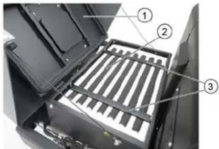
1 Seadme kate
2 Peentolmu filter
3 Risttoed
→ Avage lukk.
→ Avage filtrikate.
Toode: Imur-pühkija istmega
Tüüp: KM 105/180 R Bp 1.186-050.0 KM 105/180 R Bp Pack 1.186-051.0

Chairman of the Board of Management

Director Regulatory Affairs & Certification
71364 Winnenden (Germany)
Tel.: +49 7195 14-0
Fax: +49 7195 14-2212
Winnenden, 2020/01/01
Abi häirete korral
www.kaercher.com/REACH
Garantija
natural_image
Close-up of a mechanical component with labeled parts 1 and 2, showing internal structure (no text or symbols beyond labels)natural_image
Close-up of a computer control panel with four buttons and a white arrow pointing to one (no visible text or symbols)
natural_image
Exterior view of a black industrial machine with yellow fan and wheels (no visible text or symbols)natural_image
Interior view of an electric vehicle battery pack with labeled components (no text or symbols visible)1 L o d z i n š
natural_image
Diagram of a layered structure with a blue upward arrow, no text or symbols present1 lerīces pārsegs
2 Smalko puteklu filtrs
3 Škērsspraišli
Chairman of the Board of Management
S. Reiser Director Regulatory Affairs & Certification
Pilnvarotais sagatavot dokumentāciju: S. Reiser
Alfred Kärcher SE & Co. KG
71364 Winnenden (Germany)
Tel.: +49 7195 14-0
Fax: +49 7195 14-2212
Winnenden, 2020/01/01
www.kaercher.com/REACH
Garantija
natural_image
Close-up of a mechanical component with labeled parts 1 and 2, showing no readable text or symbols.1 Sédynès reguliavimo svirtis
2 Vairuotojo sédyné
natural_image
Close-up of a car interior control panel with colored buttons and a white arrow pointing to one (no text or symbols visible)→ ljunkite orpūte.
→ Valant plotus:
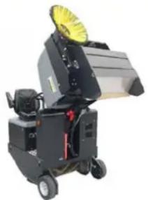
natural_image
Exterior view of a black industrial machine with yellow fan and wheels (no visible text or symbols)natural_image
Interior view of a battery pack with labeled components (no readable text or symbols)1 Dulkių maišelis
2 Apsauginis strypas
3 Besisukantis šepetys
1 Kronšteinas
2 Sparnuotoji veržlé
3 Šoninis tarpiklis
natural_image
Diagram of a layered structure with a blue upward arrow, no text or symbols present1 Prietaiso gaubtas
2 Filtro dangtelis (vibratoriaus sistema)
3 Filtro dangtelio fiksatorius (2x)
→ Prietaiso gaubta paverskite i priekj.
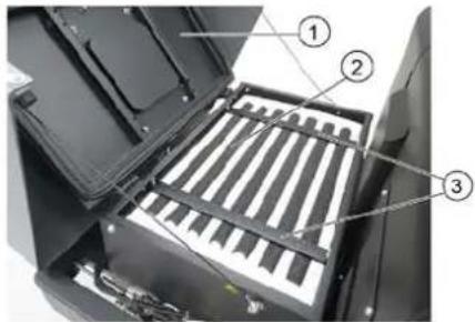
1 Prietaiso gaubtas
71364 Winnenden (Germany)
Tel.: +49 7195 14-0
Fax: +49 7195 14-2212
Winnenden, 2020/01/01
www.kaercher.com/REACH
Гарантія
natural_image
Close-up of a mechanical component with labeled parts 1 and 2, showing no readable text or symbols.natural_image
Close-up of a car interior control panel with four color-coded buttons and an arrow pointing to one (no visible text or symbols)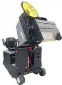
natural_image
Exterior view of a black industrial machine with yellow circular top and wheels (no visible text or symbols)natural_image
Interior view of a battery pack with labeled components (no readable text or symbols)1 Оглядове скло
1 Підтримуюу
2 Смушкова гайка
3 Бічне ущільнення
natural_image
Abstract geometric pattern with layered wavy lines and a blue upward arrow at the bottom (no text or symbols)1 Кришка пристрою
71364 Winnenden (Germany)
Tel.: +49 7195 14-0
Fax: +49 7195 14-2212
Winnenden, 2020/01/01
www.kaercher.com/REACH
质量保证
natural_image
Close-up of a mechanical component with labeled parts 1 and 2, showing internal structure (no text or symbols beyond labels)1 座位调整杆
2 驾驶员座位
natural_image
Close-up of a car interior control panel with colored buttons and a white arrow pointing to one (no visible text or symbols)→ 开启鼓风机。
→ 清扫平面时:
扫辊和侧刷操作杆(1)向后:扫辊启动。
扫辊操作杆(3)向后:扫辊降下。

natural_image
Industrial machine with yellow fan and wheels (no visible text or symbols)1 保险杠支架
2 保险杠
natural_image
Interior view of a battery pack with labeled components (no readable text or symbols)电池电极 - 沿左侧行驶方向
1 清扫垃圾箱
2 保险杠
3 清扫辊
→ 关闭设备。
1 固定架
2 蝶形螺母
3 侧面密封板
natural_image
Abstract geometric pattern with diagonal stripes and a blue upward arrow (no text or symbols)1 设备罩
2 微尘过滤器
3 横架
H. Jenner
Chairman of the Board of Management
S. Reiser
Director Regulatory Affairs & Certification
文档全权代表:
S. Reiser
Alfred Kärcher SE & Co. KG
71364 Winnenden (Germany)
Tel.: +49 7195 14-0
Fax: +49 7195 14-2212
Winnenden, 2020/01/01
故障排除
1 غطاء الجهاز
1 غطاء الجهاز
natural_image
Interior view of a battery pack with labeled components (no readable text or symbols)natural_image
Two industrial machinery components: top shows a control panel with labeled parts, bottom shows a cleaning machine with yellow filter (no visible text or symbols)


natural_image
Close-up of a car interior control panel with colored buttons and an arrow pointing to a yellow button (no text or symbols visible)
1 ذراع ضبط المqedد
2 م Expected Audience
natural_image
Black silhouette of a hand giving a thumbs-up gesture (no text or symbols)THANK YOU!
MERCI! DANKE! iGRACIAS!
Registrieren Sie Ihr Produkt und profitieren Sie von vielen Vorteilen. Register your product and benefit from many advantages. Enregistrez votre produit et bénéficier de nombreux avantages. Registre su producto y aproveche de muchas ventajas.
www.kaercher.com/welcome

Bewerten Sie Ihr Produkt und sagen Sie uns Ihre Meinung. Rate your product and tell us your opinion. Évaluer votre produit et dites-nous votre opinion. Reseñe su producto y díganos su opinión.

natural_image
Icon showing a gear and wrench, no text or symbols presentwww.kaercher.com/dealersearch
Alfred Kärcher SE & Co. KG
Alfred-Kärcher-Str. 28-40
71364 Winnenden (Germany)
Tel.: +49 7195 14-0
Fax: +49 7195 14-2212