ALC 3360GR 10.8 - Laser level Flex - Free user manual and instructions
Find the device manual for free ALC 3360GR 10.8 Flex in PDF.
| Brand | Flex |
| Model | ALC 3360GR 10.8 |
| Category | Laser level |
| Accuracy | ±0.3 mm/m |
| Operating range (without receiver) | ≤ 100 m diameter |
| Operating range (with receiver) | ≤ 120 m diameter |
| Laser type | Line laser, class II |
| Laser wavelength | 520 nm |
| Laser power | < 10 mW |
| Laser line width | ≤ 3 mm at 5 m (100 Lux) |
| Angular coverage | 360° |
| Self-leveling range | ±4° |
| Leveling time | ≤ 5 s |
| Power supply | Li-Ion battery 10.8 V (models AP 10.8/2.5 A or P 10.8/4.0) |
| Operating time (2.5 Ah battery) | ≥ 12 h (power 1), ≥ 8 h (power 2), ≥ 6.5 h (power 3) |
| Weight (without battery) | 0.8 kg |
| Operating temperature | -10 °C to 40 °C |
| Operating modes | Horizontal, vertical, two verticals, horizontal + two verticals |
| Locking function | Yes (for inclined use) |
| Outdoor mode | Yes (with recommended receiver) |
| Brightness adjustment | 2 levels indoor, dedicated outdoor mode |
| Included accessories | Swiveling magnetic bracket, suspension plate, tripod, laser viewing glasses, laser target plate, Li-Ion battery |
| Cleaning | Soft cloth, possibly pure alcohol or water, do not immerse |
| Storage | In the protective case, indoors |
Frequently Asked Questions - ALC 3360GR 10.8 Flex
User questions about ALC 3360GR 10.8 Flex
0 question about this device. Answer the ones you know or ask your own.
Ask a new question about this device
Download the instructions for your Laser level in PDF format for free! Find your manual ALC 3360GR 10.8 - Flex and take your electronic device back in hand. On this page are published all the documents necessary for the use of your device. ALC 3360GR 10.8 by Flex.
USER MANUAL ALC 3360GR 10.8 Flex
natural_image
Line drawing of a digital camera with warning labels and control buttons (no text or symbols)en Original operating instructions....16
natural_image
Line drawing of a mechanical device with control panel and warning symbols (no text or labels)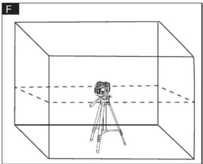
natural_image
Line drawing of a camera on a tripod inside a transparent cube, with dashed lines indicating perspective or distance (no text or symbols)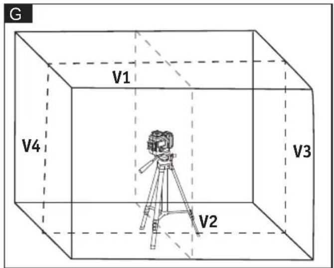
natural_image
Technical line drawing of two electronic devices with control panel and display screens (no text or symbols)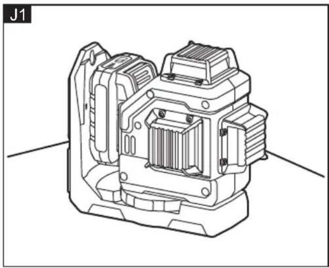
natural_image
Technical line drawing of a mechanical device with internal components (no text or symbols)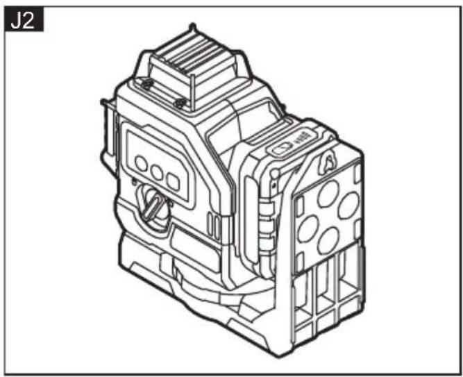
natural_image
Technical line drawing of an industrial electrical component (no text or symbols visible)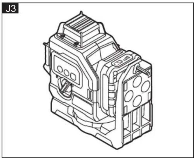
natural_image
Technical line drawing of an electrical contactor device (no text or symbols visible)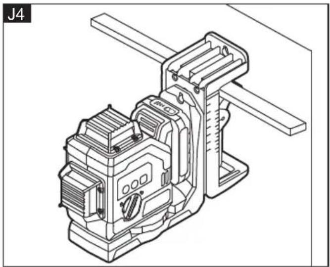
natural_image
Technical line drawing of a mechanical device with no visible text or symbols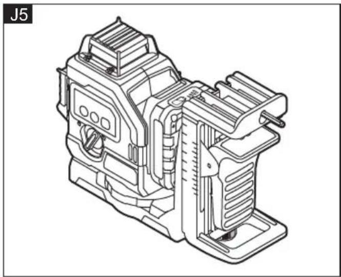
natural_image
Technical line drawing of a mechanical device (no text or symbols visible)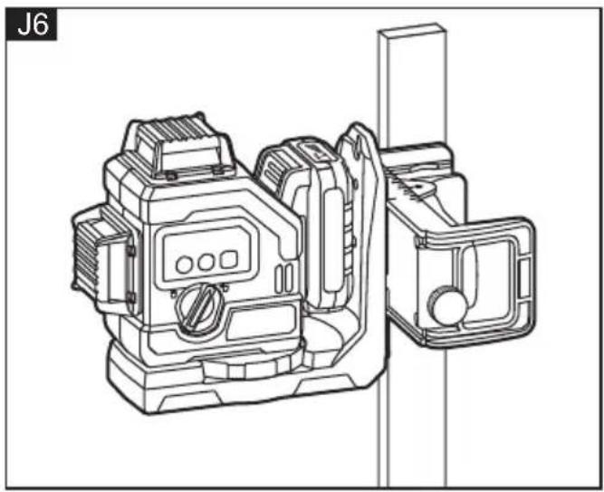
natural_image
Technical line drawing of a mechanical device with no visible text or symbols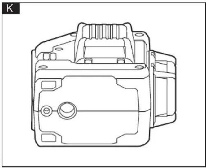
natural_image
Technical line drawing of a mechanical component (no text or symbols)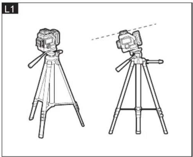
natural_image
Line drawings of two tripod-mounted cameras with tripod supports, shown from different angles (no text or symbols)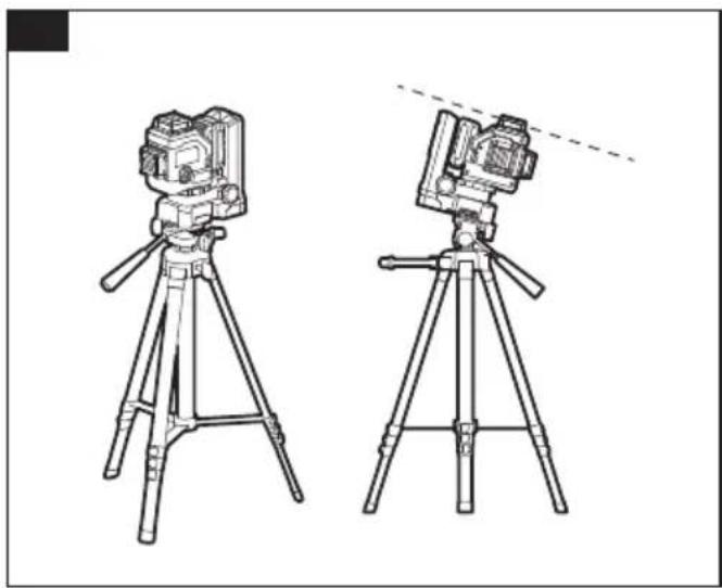
natural_image
Line drawing of two tripod-mounted cameras with tripod supports, no text or symbols present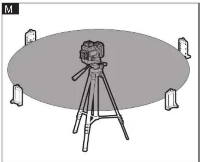
natural_image
Illustration of a camera on a tripod with four corner monitors, no text or symbols presentSymbols used in this manual

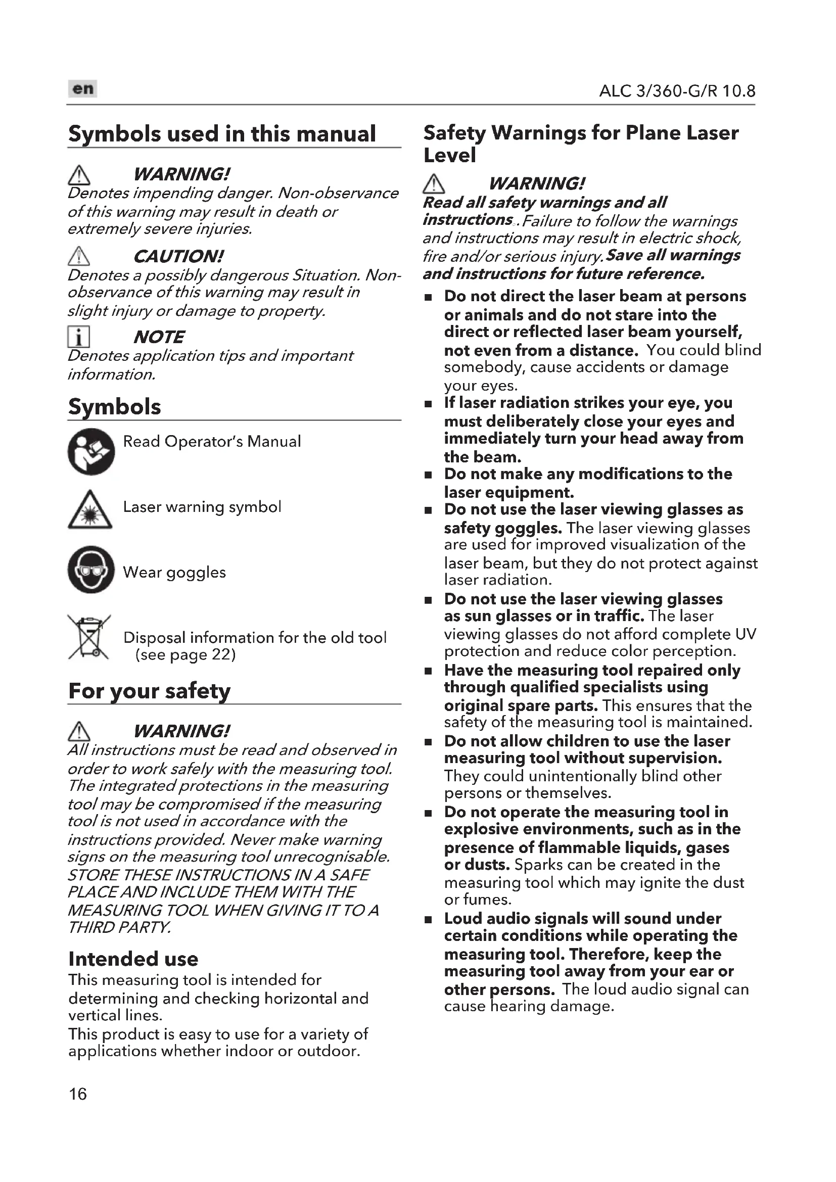
WARNING!
Denotes impending danger. Non-observance of this warning may result in death or extremely severe injuries.

CAUTION!
Denotes a possibly dangerous Situation. Non-observance of this warning may result in slight injury or damage to property.

NOTE
Denotes application tips and important information.
Symbols

Read Operator's Manual

Laser warning symbol

Wear goggles

Disposal information for the old tool (see page 22)
For your safety

WARNING!
All instructions must be read and observed in order to work safely with the measuring tool. The integrated protections in the measuring tool may be compromised if the measuring tool is not used in accordance with the instructions provided. Never make warning signs on the measuring tool unrecognisable. STORE THESE INSTRUCTIONS IN A SAFE PLACE AND INCLUDE THEM WITH THE MEASURING TOOL WHEN GIVING IT TO A THIRD PARTY.
Intended use
This measuring tool is intended for determining and checking horizontal and vertical lines.
This product is easy to use for a variety of applications whether indoor or outdoor.
Safety Warnings for Plane Laser Level

WARNING!
Read all safety warnings and all
instructions. Failure to follow the warnings and instructions may result in electric shock, fire and/or serious injury. Save all warnings and instructions for future reference.
■ Do not direct the laser beam at persons or animals and do not stare into the direct or reflected laser beam yourself, not even from a distance. You could blind somebody, cause accidents or damage your eyes.
■ If laser radiation strikes your eye, you must deliberately close your eyes and immediately turn your head away from the beam.
■ Do not make any modifications to the laser equipment.
- Do not use the laser viewing glasses as safety goggles. The laser viewing glasses are used for improved visualization of the laser beam, but they do not protect against laser radiation.
■ Do not use the laser viewing glasses as sun glasses or in traffic. The laser viewing glasses do not afford complete UV protection and reduce color perception.
■ Have the measuring tool repaired only through qualified specialists using original spare parts. This ensures that the safety of the measuring tool is maintained.
■ Do not allow children to use the laser measuring tool without supervision. They could unintentionally blind other persons or themselves.
- Do not operate the measuring tool in explosive environments, such as in the presence of flammable liquids, gases or dusts. Sparks can be created in the measuring tool which may ignite the dust or fumes.
■ Loud audio signals will sound under certain conditions while operating the measuring tool. Therefore, keep the measuring tool away from your ear or other persons. The loud audio signal can cause hearing damage.
■ Keep the measuring tool, the laser target plate 16 and the universal holder 13 away from cardiac pacemakers.
The magnets inside the measuring tool, the laser target plate and the universal holder generate a field that can impair the function of cardiac pacemakers.
- Keep the measuring tool, the laser target plate 16 and the universal holder 13 away from magnetic data carriers and magnetically sensitive devices. The effect of the magnets inside the measuring tool, the laser target plate and the universal holder can lead to irreversible data loss.
■ Ensure that battery replacement is carried out properly. There is a risk of explosion.
Technical specifications
| B | |||
| Battery type AP 10. | 8/2.5 | AP 10. | 8/4.0 |
| Working Temperature | °C -10°~40°C | ||
| Claimed voltage V | 10.8 | ||
| Working time-Power 1-power 2-Power 3 | h | AP 10.8/2.5≥12h≥8h≥6.5h | |
| Precision | mm/m | ±0.3mm/m | |
| Laser Wavelength | m 520nm | ||
| Laser Power mW | < 10mw | ||
| Laser Grade Class | I | ||
| Laser Line Width | mm/m | ≤3mm/5m(100Lux) | |
| Sector Angle ° 360° | |||
| Swing Time | S | ≤5s | |
| Working Angle | ° ≤±4° | ||
| Weight (Without Batterypack) | Kg | 0.8 | |
| Working range w/o receiver(diameter) | m | ≤100 | |
| Working range with receiver(diameter) | m | ≤120 |
*The working range may be reduced by unfavourable environmental conditions (e.g. direct sunlight).
Overview (Fig. A)
The numbering of the product features refers to the illustration of the machine on the graphics page.
1 Exit opening for laser beam
2 Indicator light for laser status
3 ON/OFF button: horizontal laser line
4 ON/OFF button: vertical laser line
5 Indicator light for Laser luminance
6 Switch button for outdoor mode and brightness control
7 Locking rotary knob
8 State of charge indicator
9 Release button for battery
10 Li-ion battery
11 Laser receiver
12 Magnetic pivoting base
13 Back hanging board
14 Tripod
15 Laser viewing glasses
16 Laser target plate
Operating instructions

WARNING!
Remove the battery before carrying out any work on the measuring tool.

CAUTION!
Protect the measuring tool against moisture and direct sun light.
Do not subject the measuring tool to extreme temperatures or variations in temperature. As an example, do not leave
it in vehicles for a long time. In case of large variations in temperature, allow the measuring tool to adjust to the ambient temperature before putting it into operation. In case of extreme temperatures or variations in temperature, the accuracy of the measuring tool can be impaired.
Avoid heavy impact to or falling down of the measuring tool. After severe exterior effects to the measuring tool, it is recommended to carry out an accuracy check (see "Accuracy Check of the Measuring Tool", page XX) each time before continuing to work.
Switch the measuring tool off during transport. When switching off, the levelling unit is locked. Else it can be damaged in case of intense movement.
Before switching on the measuring tool
Unpack the plane laser level and check that there are no missing or damaged parts.
i NOTE
The batteries are not fully charged on delivery. Prior to initial operation, charge the batteries fully. Refer to the charger operating manual.
Inserting/replacing the battery
■ Press the charged battery 10 into the power tool until it clicks into place. (Fig. C1)
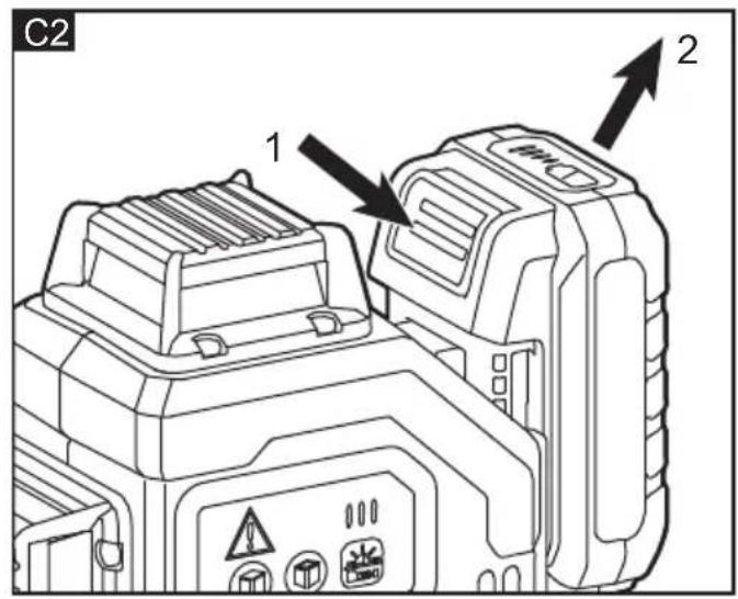
■ To remove, press the release button (1.) and pull out the battery (2.) (Fig. C2)
CAUTION!
When the device is not in use, protect the battery contacts. Loose metal parts may short-circuit the contacts; explosion and fire hazard!
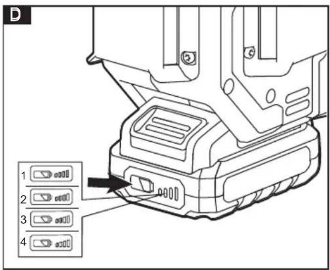
Battery state of charge
■ Press the button to check the state of charge at the state of charge indicator LEDs(8). (Fig. D)
■ The indicator goes out after 5 seconds.
■ If one of the LEDs flashes, the battery must be recharged. If none of the LEDs light up after the button is pressed, the battery is faulty and must be replaced.
Switching On and Off
WARNING!
Do not point the laser beam at persons or animals and do not look into the laser beam yourself, not even from a large distance.
CAUTION!
Do not leave the switched-on measuring tool unattended and switch the measuring tool off after use. Other persons could be blinded by the laser beam.
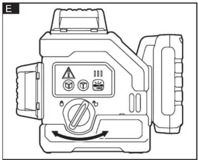
■ Rotate the locking rotary knob (7) to the "☐" position according to the arrow in the figure (Fig. E).
■ The tool is turned on and get into automatic balance mode. Immediately after switching on, the measuring tool sends laser beams out of the exit openings (1). Default the horizontal laser H is only turned on (Fig. F).
- Rotate the locking rotary knob (7) to the "🔒" position according to the arrow in the figure to turn off the tool (Fig. E).
Operating Modes
The measuring tool has several operating modes between which you can switch at any time. These are for:
- Generating a horizontal laser plane
- Generating a vertical laser plane,
- Generating two vertical laser planes,
- Generating a horizontal laser plane as well as two vertical laser planes.
After you switch it on, the measuring tool generates a horizontal laser plane. To change the operating mode, press the key "horizontal laser line (3)" or "vertical laser line (4)".
CAUTION!
Select the appropriate mode before using the tool.
The position of laser maybe changes if move or vibrate the tool while it is being used.
Select the laser mode
Press the key "horizontal laser line (3)" or "vertical laser line (4)" to select a specific laser projection mode whether in auto-leveling mode or lock mode.
Horizontal laser line control
■ Press the key "horizontal laser line (3)" to turn on or turn off the horizontal laser line.
■ The horizontal laser line H is a 360° horizontal laser (Fig.F).
Vertical laser lines control
- Press the key "vertical laser line (4)" to turn on or turn off both groups of the vertical laser lines V1V2 and V3V4 (Fig.G).
Auto-leveling mode
NOTE
The indicator light (2) will be red flashing with buzzer warning and the laser will keep flashing, while the tool cannot finish auto-leveling.
If auto-leveling is always not possible, it means the surface on which the tool stands deviates by more than auto-leveling range 4^ from the horizontal plane. Please place the tool in a position closed to level ( ≤4^ from the horizontal plane).
■ Position the measuring tool on a level and firm support, attach to the tripod.
■ Push the locking rotary knob (7) to the "☐" position.
i NOTE
After switching on, the levelling function automatically compensates irregularities within the self-levelling range of ±4^ . The levelling is finished as soon as the laser beams do not move any more.
Vertical laser line
- When the horizontal laser line is lit up, press the key "vertical laser line (4)" to control the vertical lines V1V2 and V3V4 to light up or just to the side, or off at the same time.
- When the horizontal laser line is not lit up, press the key "vertical laser line (4)" to control the vertical lines V1V2 and V3V4 to light up or only on the side, but the two groups of vertical laser lines cannot be completely turned off at the same time.
Horizontal laser line
- Only when at least 1 group of vertical laser lines is lit up, the horizontal laser line can be turned off.
Work without auto-leveling mode (Lock mode)
This mode always be used as adjust or mark the line exceeds 4^ from the horizontal plane. For example, set up the stair rail.
NOTE
■ Pay attention that the tool will not come out any warning sound in this mode even it exceeds the auto-leveling range 4°. This mode cannot be used to perform horizontal or vertical leveling.
- Keep the locking rotary knob in “🔒” position, press the key “horizontal laser line (3)” or “vertical laser line (4)” for a long time to open the corresponding laser, the tool will work in lock mode.
■ Press the key "horizontal laser line (3)" or "vertical laser line (4)" to select a specific laser projection mode.
■ The indicator light (2) will always be red to caution the function mode;
■ Position the tool naturally at the desired angle and then go on working with the laser to proceed to the next step.
■ After the laser is all off, the tool shuts down simultaneously.
Outdoor mode
■ Press the switch button (6) for a while to select outdoor mode. The laser will dim a little while in outdoor mode, which is normal.
■ Please use the tool with a receiver (sold separately) while in outdoor mode.
Indicator light
Indoor mode
■ Default indoor mode after starting up the tool.
■ At this moment, the indicator light (5) comes on two on the left
■ Short press switch button (6) to select different brightness.
Outdoor mode
Long press the switch button (6), and then the indicator light (5) will only light up one on the far left and it will be flashing, prompting to enter the outdoor mode.
Accuracy Check of the Measuring Tool
Influences on Accuracy
■ The ambient temperature has the greatest influence. Especially temperature differences occurring from the ground upward can divert the laser beam.
■ Because the largest difference in temperature layers is close to the ground, the measuring tool should always be mounted on a tripod when measuring distances exceeding 20m. If possible, also set up the measuring tool in the center of the work area.
In addition to external influences, device-specific influences (e.g. falls or heavy impacts) can also lead to deviations. For this reason, check the levelling accuracy each time before beginning work.
■ Firstly, check the levelling accuracy of the horizontal laser line and then the levelling accuracy of the vertical laser lines.
■ Should the measuring tool exceed the maximum deviation during one of the tests, please have it repaired by a Flex after-sales service.
Checking the Horizontal Levelling Accuracy
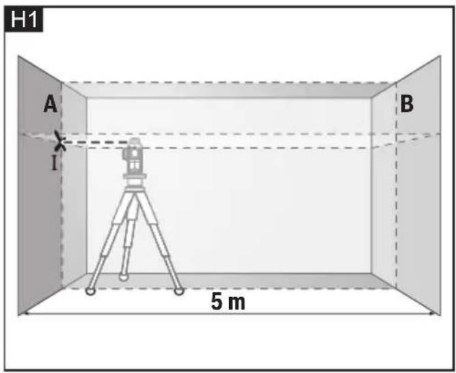
For this check, a free measuring distance of 5 m on a firm surface between two walls A and B is required.
- Mount the measuring tool onto a tripod, or place it on a firm and level surface close to wall A. Switch on the measuring tool to operation with automatic levelling. Select the operating mode in which a horizontal laser plane as well as a vertical laser plane in front of the measuring tool are generated. (Fig.H1)
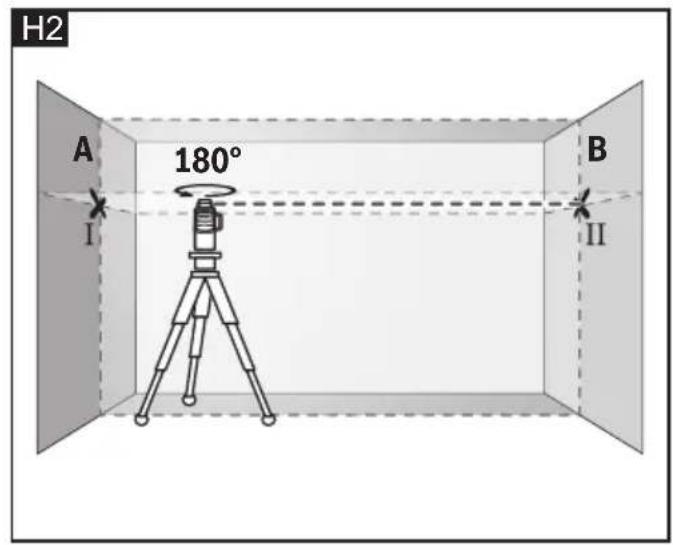
- Direct the laser against the close wall A and allow the measuring tool to level in. Mark the centre of the point where the laser lines cross each other at wall A (point I). (Fig.H2)
- Turn the measuring tool by 180^ , allow it to level in and mark the cross point of the laser lines on the opposite wall B (point II).
-
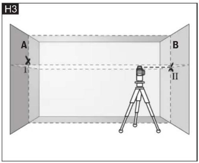
Without turning the measuring tool, position it close to wall B. Switch the measuring tool on and allow it to level in. (Fig.H3)
-
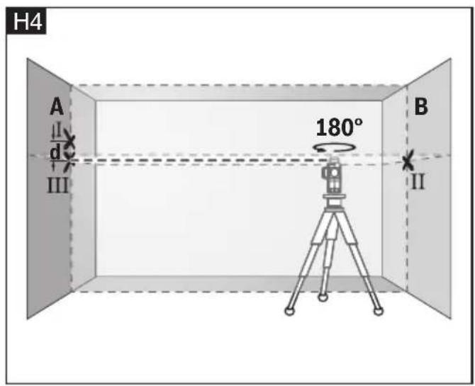
Align the height of the measuring tool (using a tripod or by underlaying, if required) in such a manner that the cross point of the laser lines is projected against the previously marked point II on the wall B. (Fig.H4)
- Without changing the height, turn around the measuring tool by 180^ . Direct it against the wall A in such a manner that the vertical laser line runs through the already marked point I. Allow the measuring tool to level in and mark the cross point of the laser lines on the wall A (point III).
- The difference d of both marked points I and III on wall A results in the actual height deviation of the measuring tool alongside the lateral axis.
On the measuring distance of 2 × 5 m = 10 m , the maximum allowable deviation is: 10 m × ± 0.3 mm/m = ± 3 mm .
Thus, the difference d between points I and III must not exceed 3 mm (max.).
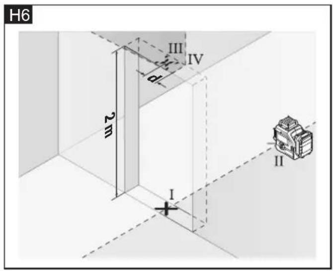
Checking the Levelling Accuracy of the Vertical Lines
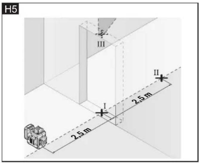
For this check, a door opening is required with at least 2.5 m of space (on a firm surface) to each side of the door.
- Position the measuring tool on a firm, level surface (not on a tripod) 2.5m away from the door opening. Switch on the measuring tool to operation with automatic levelling. Select an operating mode in which a vertical laser plane is generated in front of the measuring tool. (Fig.H5)
- Mark the centre of the vertical laser line at the floor of the door opening (point I), at a distance of 5 m beyond the other side of the door opening (point II) and at the upper edge of the door opening (point III). (Fig.H6)
- Rotate the measuring tool by 180^ and position it on the other side of the door opening directly behind point II. Allow the measuring tool to level in and align the verticallaser line in such a manner that its centre runs exactly through points I and II.
- Mark the centre of the laser line at the upper edge of the door opening as point IV.
- The difference d of both marked points III and IV results in the actual deviation of the measuring tool to the plumb line.
- Measure the height of the door opening. Repeat the measuring procedure for the second vertical laser plane. For this, select an operating mode in which a vertical laser plane is generated aside of the measuring tool, and turn the measuring tool by 90^ before beginning with the measuring procedure.
The maximum admissible deviation is calculated as follows:
Doubled height of the door opening x 0.3 mm/m Example: For a door-opening height of 2m, the maximum deviation may be 2 x 2m x ±0.3 mm/m = ±1.2 mm. Consequently, points III and IV may be no more than 1.2 mm (max.) apart from each other for each of both measurements.
Accessories
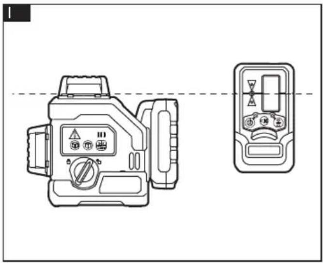
Laser receiver (sold separately)
Use the laser receiver 11 to improve detection of the laser lines in adverse lighting conditions (outdoor, bright environment, direct sunlight) and over greater distances. (Fig.1)
Magnetic Pivoting base / Back hanging board
■ With the magnetic pivoting base (12) / back hanging bracket (13), you can fasten the measuring tool, e.g., to vertical surfaces, pipes, pillar or magnetizable materials.
■ The magnetic pivoting base (12) / back hanging bracket (13) can also make the measuring tool with 2.5 Ah battery pack turn around 180 degree as you like.
■ Adjust the magnetic pivoting base (12)/back hanging bracket (13) roughly before switching on the measuring tool.
Working with the magnetic pivoting base / back hanging board
The magnetic pivoting base
- mounted on the working plane directly (Fig.J1).
- attached to the steel or metal wall by magnets at the back (Fig.J2).
- fastened to the wall by screw (Fig.J3).
-
fixed on the upholder by clamping on the back hanging board (Fig.J4).
-
fixed on the wall surface by back hanging board and screw (not included) (Fig.J5).
- fixed on the upright column by the clamp of the back hanging board (Fig.J6).
Tripod (not included)
■ By the tripod the tool can easily be adjusted to a proper height and orientation.
■ This tool can be mounted onto the thread of a general 1/4" or 5/8" tripod directly (Fig.K).
■ Tighten the measuring tool with the tripod mounting stud.
■ Adjust the tripod roughly before switching on the measuring tool.
Working mode
- Working with the tripod directly (Fig.L1).
- Working through a magnetic pivoting base(Fig.L2)
Laser Viewing Glasses
The laser viewing glasses filter out ambient light. This enhances the laser visibility for the eye.
NOTICE:
Do not use the laser viewing glasses as safety goggles. The laser viewing glasses are used for improved visualization of the laser beam, but they do not protect against laser radiation.
Do not use the laser viewing glasses as sun glasses or in traffic. The laser viewing glasses do not afford complete UV protection and reduce color perception.
Laser Target Plate
■ Position the laser plate on the target, and whether the height of the targets is equal is determined by comparing the distance between the laser line on the laser plate and the target.
■ The laser target plate 16 increases the visibility of the laser beam under unfavorable conditions and at large distances.
Working with the laser target plate (e.g.)
- Determine whether the column height is equal (Fig.M).
Maintenance and care

WARNING!
In order to maintain the product performance, you should always follow these simple directions below.
Cleaning
- Keep the measuring tool clean at all times.
■ Do not immerse the measuring tool in water or other fluids.
■ Always keep the product free of dust and liquids as much as possible. Use only a clean, soft cloth for cleaning. If necessary, slightly moisten the cloth with pure alcohol or a little water. Do not use any cleaning agents or solvents. Do not Wash with water directly.
■ Do not touch the lens with your fingers.
■ Regularly clean the surfaces at the exit opening of the laser in particular, and pay attention to any fluff or fibers.
Storage
■ Always store the product indoors. Always handle or store the product with original packaging parts.
■ Store and transport the measuring tool only in the protective pouch or in the case.
Battery
■ While the product not been in use for long time, do regular inspection on the batteries. Take off the batteries or charge and discharge the Li-ion battery to extend the service life.
■ Charge the Li-ion battery or change the batteries when the low battery capacity warning occurs.
Repairs
■ Do not attempt to repair or disassemble the product. Any repair or disassemble required on this product should be performed only by authorized service personnel, otherwise serious injury may occur.
Spare parts and accessories
Exploded drawings and spare-part lists can be found on our homepage:
www.flex-tools.com
Disposal information

WARNING!
Render redundant tools unusable:
- mains operated tool by removing the power cord,
– battery operated tool by removing the battery.

EU countries only Do not throw electric power tools into the household waste!
In accordance with the European Directive 2012/19/EC on Waste Electrical and Electronic Equipment and transposition into national law used electric power tools must be collected separately and recycled in an environmentally friendly manner.

Raw material recovery instead of waste disposal.
Device, accessories and packaging should be recycled in an environmentally friendly manner. Plastic parts are identified for recycling according to material type.

WARNING!
Do not throw batteries into the household waste, fire or water. Do not open used batteries. EU countries only: In accordance with Directive 2006/66/EC defective or used batteries must be recycled.

NOTE
Please ask your dealer about disposal options!
C €-Declaration of Conformity
We declare under our sole responsibility that the product described under "Technical specifications" conforms to the following standards or normative documents:
EN 60745 in accordance with the regulations of the directives 2014/30/EC, 2006/42/EC, 2011/65/EC.
Responsible for technical documents:
Technical Head Head of Quality
Department (QD)
Exemption from liability
The manufacturer and his representative are not liable for any damage and lost profit due to interruption in business caused by the product or by an unusable product. The manufacturer and his representative are not liable for any damage which was caused by improper use of the product or by use of the product with products from other manufacturers.
Technical specifications
Trépied (non fourni)
Peter Lameli Klaus Peter Weinper Technical Head Head of Quality
Department (QD)
10m x ± 0.3 mm/m = ± 3 mm.
Peter Lameli Klaus Peter Weinper Technical Head Head of Quality
Department (QD)
Peter Lameli Klaus Peter Weinper Technical Head Head of Quality
Department (QD)
Peter Lameli Klaus Peter Weinper Technical Head Head of Quality Department
(QD)
Peter Lameli Klaus Peter Weinper Technical Head Head of Quality
Department (QD)
Technical Head Head of Quality Department (QD)
10m x ± 0.3 mm/m = ± 3 mm.
Peter Lameli Klaus Peter Weinper Technical Head Head of Quality
Department (QD)
Technical Head Head of Quality
Department (QD)
Peter Lameli Klaus Peter Weinper Technical Head Head of Quality
Department (QD)
Technical Head Head of Quality
Department (QD)
Technical Head Head of Quality
Department (QD)
Technical Head Head of Quality
Department (QD)
Peter Lameli Technical Head
Klaus Peter Weinper Head of Quality Department (QD)