
BV 170 - Heating Master - Free user manual and instructions
Find the device manual for free BV 170 Master in PDF.
| Product type | Mobile professional hot air heater |
| Brand | Master |
| Model | BV 170 |
| Fuel | HVO 100 Biofuel, Diesel B7, Kerosene |
| Combustion type | Direct or indirect depending on model |
| Power supply | 220-240V / 110-120V (DV models) |
| Heating power | 170,000 BTU/h (approx. 50 kW) |
| Dimensions (approx.) | 800 x 500 x 500 mm |
| Weight (approx.) | 35 kg |
| Safety distance in front | 2.5 m |
| Safety distance sides, top, rear | 1.5 m |
| Tank capacity | Not specified |
| Filters | Loading filter, suction filter, pump filter |
| Recommended cleaning | Depending on fuel quality |
| Safety | Safety thermostat, solenoid valve, fuse, manual reset |
| Usage | Well-ventilated areas, temporary professional use |
| Thermostat connection | Possible (option) |
| Repairability | Spare parts available, service center |
Frequently Asked Questions - BV 170 Master
User questions about BV 170 Master
0 question about this device. Answer the ones you know or ask your own.
Ask a new question about this device
Download the instructions for your Heating in PDF format for free! Find your manual BV 170 - Master and take your electronic device back in hand. On this page are published all the documents necessary for the use of your device. BV 170 by Master.
USER MANUAL BV 170 Master
IMPORTANT: Please use only one of the following fuels: HVO 100 Biofuel, Diesel B7 and Kerosene.

IMPORTANT: In order to have a correct function you must use an electrical generator in class G3 or more (frequency variation ±1%, on variation ±2%). The maximum power of electrical generator must be three time the nominal power of device that you must connect.
TECHNICAL DATA TABLE - TABELLA DATI TECHNICI - TECHNISCHE DATENTABELLE - TABLA DE DATOS TECNICOS - TABLEAU DES DONNÉES TECHNIQUES - TABEL TECHNISCHE GEGEVENS - TABELA DE DADOS TÉCNICOS - TEKNISK DATATABEL - TEKNISTEN TIETOJEN TAULUKKO - TABELL FOR TEKNISKE DATA - TABELL MED TEKNISKA EGENSKAPER - TABELA DANYCH TECHNICZNYCH - TABLIUE TEXHNUCKNX DAHHbIX - TABULKA TECHNICKYCH UDAJU - MUSZAKI ADATOK TÁBLAZATA - TEHNICNI PODATKI - TEKNIK VERILER TABLOSUNDA - TABLICI S TEHNICKIM PODACIMA - TECHNINI DUOMENU LENTELEJE - TEHNISKO DATU TABULA - TEHNILISTE ANDMETE TABEL - TABELUL CU DATE TEHNICE - TABULKA TECHNICKYCH UDAJOV - TABLIUCA TEXHNUCKNX DAHHN - TABLIU CI TEXHIVHIX DAHNX - TABELI SA TEHNICKIM PODACIMA - INAKIAA TON TEXNIKON ΣTOIXEION - 技术参数 - TEXHNKAJbIK KÖPCETKIWTEP KECTECI
| MAX | B 230 B 360 | |
| 65 kW-κВт 56.000 kcal/h-κкал/ч 222.000 Btu/h-БТЕ/ч | 111 kW-κВт 95.460 kcal/h-κкал/ч 379.000 Btu/h-БТЕ/ч | |
| 3.000 m³/h-M³/ч 3.300 m³/h-M³/ч | ||
| 5,2 kg/h-κг/ч 8,83 kg/h-κг/ч | ||
| DIESEL-HVO100-KEROSENE Дизель-HVO100-Керосин | DIESEL-HVO100-KEROSENE Дизель-HVO100-Керосин | |
| 65 I-л 105 I-л | ||
| ~220-240 V-B (-15%÷10%) 50 Hz-Гц 3,5 A 0,8 kW-κВт | ~220-240 V-B (-15%÷10%) 50 Hz-Гц 4,6 A 1,06 kW-κВт | |
| ~110-120 V-B (-15%÷10%) 50 Hz-Гц 7,5 A 0,8 kW-κВт | ~110-120 V-B (-15%÷10%) 50 Hz-Гц 9,2 A 1,06 kW-κВт | |
| 57 kg-κг 86 kg-κг | ||
| 1,25 US gal/h 80°SDANFOSS | 2,00 US gal/h 80°HDANFOSS | |
| 1.200 kPa-κПа 12 bar-бap | 1.300 kPa-κПа 13 bar-бap |

IMPORTANT: Please use only one of the following fuels: HVO 100 Biofuel, Diesel B7 and Kerosene.

IMPORTANT: In order to have a correct function you must use an electrical generator in class G3 or more (frequency variation ±1%, on variation ±2%). The maximum power of electrical generator must be three time the nominal power of device that you must connect.
TECHNICAL DATA TABLE - TABELLA DATI TECHNICI - TECHNISCHE DATENTABELLE - TABLA DE DATOS TECNICOS - TABLEAU DES DONNÉES TECHNIQUES - TABEL TECHNISCHE GEGEVENS - TABELA DE DADOS TÉCNICOS - TEKNISK DATATABEL - TEKNISTEN TIETOJEN TAULUKKO - TABELL FOR TEKNISKE DATA - TABELL MED TEKNISKA EGENSKAPER - TABELA DANYCH TECHNICZNYCH - TABLIUE TEXHNUCKNX DAHHbIX - TABULKA TECHNICKYCH UDAJU - MUSZAKI ADATOK TÁBLAZATA - TEHNICNI PODATKI - TEKNIK VERILER TABLOSUNDA - TABLICI S TEHNICKIM PODACIMA - TECHNINI DUOMENU LENTELEJE - TEHNISKO DATU TABULA - TEHNILISTE ANDMETE TABEL - TABELUL CU DATE TEHNICE - TABULKA TECHNICKYCH UDAJOV - TABLIULA TEXHNUCKNX DAHHN - TABLIUNI TEXHNUHIX DAHNX - TABELI SA TEHNICKIM PODACIMA - INAKIAA TON TEXNIKON ΣTOIXEION - 技术参数 - TEXHNAJIbIK KÖPCETKIUTEP KECTECI
| MAX | B 230DV B 360DV | |
| 65 kW-κВТ56.000 kcal/h-κкал/ч222.000 Btu/h-БТЕ/ч | 111 kW-κВТ95.460 kcal/h-κкал/ч379.000 Btu/h-БТЕ/ч | |
| 88 | 3.000 m³/h-M³/ч 3.300 m³/h-M³/ч | |
| 5,2 kg/h-κг/ч 8,83 kg/h-κг/ч | ||
| DIESEL-HVO100-KEROSENEДизель-HVO100-KEROSIN | DIESEL-HVO100-KEROSENEДизель-HVO100-KEROSIN | |
| 65 I-л 105 I-л | ||
| ~110/240 V-B (-15%÷10%)50 Hz-Γι7,5/3,5 A 0,8 kW-κВт | ~110/240 V-B (-15%÷10%)50 Hz-Γι9,2/4,6 A 1,06 kW-κВт | |
| 57 kg-κг 86 kg-κг | ||
| 1,25 US gal/h 80°SDANFOSS | 2,00 US gal/h 80°HDANFOSS | |
| 1.200 kPa-κПа12 bar-6ap | 1.300 kPa-κПа13 bar-6ap |

IMPORTANT: Please use only one of the following fuels: HVO 100 Biofuel, Diesel B7 and Kerosene.

IMPORTANT: In order to have a correct function you must use an electrical generator in class G3 or more (frequency variation ±1%, n variation ±2%). The maximum power of electrical generator must be three time the nominal power of device that you must connect.
TECHNICAL DATA TABLE - TABELLA DATI TECHNICI - TECHNISCHE DATENTABELLE - TABLADATLABUS TECNICOS - TABLEAU DES DONNÉES TECHNIQUES - TABEL TECHNISCHEGEGEVENS - TABELA DE DADOS TECNICOS - TEKNISK DATATABEL - TEKNISTEN TIETOJENTAUUKKO - TABELL FOR TEKNISKE DATA - TABELL MED TEKNISKA EGENSKAPER -TABELA DANYCH TECHNICZNYCH - TABLIUE TEXHNUCKNX DAHHbIX - TABULKATECHNICKYCH UDAJU - MUSZAKI ADATOK TABLAZATA - TEHNICNI PODATKI - TEKNIKVERILER TABLOSUNDA - TABLICI S TEHNICKIM PODACIMA - TECHNINI DUOMENULENTELEJE - TEHNISKO DATU TABULA - TEHNILISTE ANDMETE TABEL - TABELUL CUDATE TEHNICE - TABULKA TECHNICKYCH UDAJOV - TABLIUa TEXHNUCKIN DAHHIN- TABLIUI TEXHUYHX DAHNX - TABELI SA TEHNICKIM PODACIMA - INAKIAA TONTEXNIKON 2TOIXEION - 技术参数 - TEXHNKAJbIK KOPCETKIWTEP KECTECI
| MAX | BV 69E BV 77E | |
| 21 kW-κВт18.100 kcal/h-κkan/ч71.700 Btu/h-BTE/ч | 21 kW-κВт18.100 kcal/h-κkan/ч71.700 Btu/h-BTE/ч | |
| S | 1.550 m3/h-M3/ч 1.550 m3/h-M3/ч | |
| 1,67 kg/h-κг/ч 1,67 kg/h-κг/ч | ||
| DIESEL-HVO100-KEROSENEДизель-HVO100-керocин | DIESEL-HVO100-KEROSENEДизель-HVO100-керocин | |
| 36 I-л 36 I-л | ||
| ~220-240 V-B (-15%÷10%)50 Hz-Γι1,5 A 0,3 kW-κВт | ~220-240 V-B (-15%÷10%)50 Hz-Γι1,5 A 0,3 kW-κВт | |
| ~110-120 V-B (-15%÷10%)50 Hz-Γι3 A 0,3 kW-κВт | ~110-120 V-B (-15%÷10%)50 Hz-Γι3 A 0,3 kW-κВт | |
| 33 kg-κr 33 kg-κr | ||
| 0,40 US gal/h 80°SDANFOSS | 0,40 US gal/h 80°SDANFOSS | |
| 1.200 kPa-κПа12 bar-бap | 1.200 kPa-κПа12 bar-бap |

IMPORTANT: Please use only one of the following fuels: HVO 100 Biofuel, Diesel B7 and Kerosene.

IMPORTANT: In order to have a correct function you must use an electrical generator in class G3 or more (frequency variation ±1%, on variation ±2%). The maximum power of electrical generator must be three time the nominal power of device that you must connect.
TECHNICAL DATA TABLE - TABELLA DATI TECHNICI - TECHNISCHE DATENTABELLE - TABLA DE DATOS TECNICOS - TABLEAU DES DONNÉES TECHNIQUES - TABEL TECHNISCHE GEGEVENS - TABELA DE DADOS TÉCNICOS - TEKNISK DATATABEL - TEKNISTEN TIETOJEN TAULUKKO - TABELL FOR TEKNISKE DATA - TABELL MED TEKNISKA EGENSKAPER - TABELA DANYCH TECHNICZNYCH - TABLIUE TEXHNUCKNX DAHHbIX - TABULKA TECHNICKYCH UDAJU - MUSZAKI ADATOK TÁBLAZATA - TEHNICNI PODATKI - TEKNIK VERILER TABLOSUNDA - TABLICI S TEHNICKIM PODACIMA - TECHNINI DUOMENU LENTELEJE - TEHNISKO DATU TABULA - TEHNILISTE ANDMETE TABEL - TABELUL CU DATE TEHNICE - TABULKA TECHNICKYCH UDAJOV - TABLIUA TEXHNUCKN DAHHN - TABLIUI TEXHNUHX DAHNX - TABELI SA TEHNICKIM PODACIMA - INAKIDA TONTEXNIKON ΣTOIXEION - 技术参数 - TEXHNKAJbIK KOPCETKIUTEP KECTECI
| MAX | BV 69DV BV 77DV | |
| 21 kW-κВт 18.100 kcal/h-κкал/ч 71.700 Btu/h-БТЕ/ч | 21 kW-κВт 18.100 kcal/h-κкал/ч 71.700 Btu/h-БТЕ/ч | |
| 1.550 m³/h-M³/ч 1.550 m³/h-M³/ч | ||
| 1,67 kg/h-κг/ч 1,67 kg/h-κг/ч | ||
| DIESEL-HVO100-KEROSENE Дизelines-HVO100-keposин | DIESEL-HVO100-KEROSENE Дизelines-HVO100-keposин | |
| 36 I-л 36 I-л | ||
| ~110/240 V-B (-15%÷10%) 50 Hz-Γι 3/1,5 A 0,3 kW-κВт | ~110/240 V-B (-15%÷10%) 50 Hz-Γι 3/1,5 A 0,3 kW-κВт | |
| 33 kg-κr 33 kg-κr | ||
| 0,40 US gal/h 80°SDANFOSS | 0,40 US gal/h 80°SDANFOSS | |
| 1.200 kPa-κПа 12 bar-бap | 1.200 kPa-κПа 12 bar-бap |

IMPORTANT: Please use only one of the following fuels: HVO 100 Biofuel, Diesel B7 and Kerosene.

IMPORTANT: In order to have a correct function you must use an electrical generator in class G3 or more (frequency variation ±1%, on variation ±2%). The maximum power of electrical generator must be three time the nominal power of device that you must connect.
TECHNICAL DATA TABLE - TABELLA DATI TECHNICI - TECHNISCHE DATENTABELLE - TABLADATLABUS TECNICOS - TABLEAU DES DONNÉES TECHNIQUES - TABEL TECHNISCHEGEGEVENS - TABELA DE DADOS TECNICOS - TEKNISK DATATABEL - TEKNISTEN TIETOJENTAULUKKO - TABELL FOR TEKNISKE DATA - TABELL MED TEKNISKA EGENSKAPER -TABELA DANYCH TECHNICZNYCH - TABLIUE TEXHNUCKNX DAHHbIX - TABULKATECHNICKYCH UDAJU - MUSZAKI ADATOK TABLAZATA - TEHNICNI PODATKI - TEKNIKVERILER TABLOSUNDA - TABLICI S TEHNICKIM PODACIMA - TECHNINI DUOMENULENTELEJE - TEHNISKO DATU TABULA - TEHNILISTE ANDMETE TABEL - TABELUL CUDATE TEHNICE - TABULKA TECHNICKYCH UDAJOV - TABLIULA TEXHNUCKINDAHHIN- TABLIUITEXHIUYHX DAHNX - TABELI SA TEHNICKIM PODACIMA - INAKIAA TONTEXNIKON 2TOIXEION - 技术参数 - TEXHNKAJbIK KOPCETKIWTEP KECTECI
| BV 110E BV 170E BV 290E | ||
| MAX | 34 kW-KBTV29.200 kcal/h-Kkcal/h116.000 Btu/h-BTE/h | 49 kW-KBTV42.100 kcal/h-Kkcal/h167.200 Btu/h-BTE/h |
| 8 | 1.800 m³/h-M³/h 1.800 | m³/h-M³/h 3.300 m³/h-M³/h |
| 2,71 kg/h-Kr/ч 3,9 kg | h-Kr/ч 6,8 kg/h-Kr/ч | |
| DIESEL-HVO100-KEROSENEni3eNb-HVO100-keposin | DIESEL-HVO100-KEROSENEni3eNb-HVO100-keposin | |
| 65 l-л 65 l-л 105 | -l | |
| ~220-240 V-B (-15%÷10%)50 Hz-Гц3,5 A 0,8 kW-KВт | ~220-240 V-B (-15%÷10%)50 Hz-Гц3,5 A 0,8 kW-KВт | |
| ~110-120 V-B (-15%÷10%)50 Hz-Гц7,5 A 0,8 kW-KВт | ~110-120 V-B (-15%÷10%)50 Hz-Гц7,5 A 0,8 kW-KВт | |
| 61 kg-кг 67 kg-кг | 101 kg-кг | |
| 0,65 US gal/h 80°SDANFOSS | 1,00 US gal/h 80°SDANFOSS | |
| 1.200 kPa-кПа12 bar-бap | 1.000 kPa-кПа10 bar-бap |

IMPORTANT: Please use only one of the following fuels: HVO 100 Biofuel, Diesel B7 and Kerosene.

IMPORTANT: In order to have a correct function you must use an electrical generator in class G3 or more (frequency variation ±1%, on variation ±2%). The maximum power of electrical generator must be three time the nominal power of device that you must connect.
TECHNICAL DATA TABLE - TABELLA DATI TECHNICI - TECHNISCHE DATENTABELLE - TABLA DE DATOS TECNICOS - TABLEAU DES DONNÉES TECHNIQUES - TABEL TECHNISCHE GEGEVENS - TABELA DE DADOS TÉCNICOS - TEKNISK DATATABEL - TEKNISTEN TIETOJEN TAULUKKO - TABELL FOR TEKNISKE DATA - TABELL MED TEKNISKA EGENSKAPER - TABELA DANYCH TECHNICZNYCH - TABLIUE TEXHNUCKNX DAHHbIX - TABULKA TECHNICKYCH UDAJU - MUSZAKI ADATOK TÁBLAZATA - TEHNICNI PODATKI - TEKNIK VERILER TABLOSUNDA - TABLICI S TEHNICKIM PODACIMA - TECHNINI DUOMENU LENTELEJE - TEHNISKO DATU TABULA - TEHNILISTE ANDMETE TABEL - TABELUL CU DATE TEHNICE - TABULKA TECHNICKYCH UDAJOV - TABLIUA TEXHNUCKN DAHHN - TABLIUI TEXHNUHX DAHNX - TABELI SA TEHNICKIM PODACIMA - INAKIDA TONTEXNIKON ΣTOIXEION - 技术参数 - TEXHNKAJbIK KOPCETKIUTEP KECTECI
| MAX | BV 110DV BV 170DV BV 290DV | ||
| 34 kW-KBt 29.200 kcal/h-Kkaj/ч 116.000 Btu/h-BTE/ч | 49 kW-KBt 42.100 kcal/h-Kkaj/ч 167.200 Btu/h-BTE/ч | 85 kW-KBt 73.100 kcal/h-Kkaj/ч 290.000 Btu/h-BTE/ч | |
| 1.800 m³/h-M³/ч 1.800 | m³/h-M³/ч 3.300 m³/h-M³/ч | ||
| 2,71 kg/h-Kr/ч 3,9 kg/ | h-Kr/ч 6,8 kg/h-Kr/ч | ||
| DIESEL-HVO100-KEROSENE Дизelines-HVO100-Керосин | DIESEL-HVO100-KEROSENE Дизelines-HVO100-Керосин | DIESEL-HVO100-KEROSENE Дизelines-HVO100-Керосин | |
| 65 I-л 65 I-л 105 | -л | ||
| ~110/240 V-B (-15%÷10%) 50 Hz-Гц 7,5/3,5 A 0,8 kW-KBT | ~110/240 V-B (-15%÷10%) 50 Hz-Гц 7,5/3,5 A 0,8 kW-KBT | ~110/240 V-B (-15%÷10%) 50 Hz-Гц 9,2/4,6 A 0,8 kW-KBT | |
| 61 kg-кг 67 kg-кг | 101 kg-кг | ||
| 0,65 US gal/h 80°SDANFOSS | 1,00 US gal/h 80°SDANFOSS | 1,50 US gal/h 80°SDANFOSS | |
| 1.200 kPa-кПа 12 bar-бap | 1.000 kPa-кПа 10 bar-бap | 1.200 kPa-кПа 12 bar-бap | |

IMPORTANT: Please use only one of the following fuels: HVO 100 Biofuel, Diesel B7 and Kerosene.

IMPORTANT: In order to have a correct function you must use an electrical generator in class G3 or more (frequency variation ±1%, on variation ±2%). The maximum power of electrical generator must be three times the nominal power of device that you must connect.
PICTURES - FIGURE - ABBILDUNGEN - FIGURES - FIGURES - FIGUREN - FIGURES - FIGURER - KUVAT - FIGURER - FIGUR - RYSUNKI - PNCYHKN - OBRAZKY - ABRAK - SLIKE - SEKILLER - SLIKE - PAVEIKSLÉLIAI - ATTÉLI - JOONISED - IMAGINI - OBRAZKY - ΦИГΥРΑ - MAJIIOHΚΝ - SLIKE - EIKONEΣ - 图 - CYPETTEP
PICTURES - FIGURE - ABBILDUNGEN - FIGURES - FIGURES - FIGUREN - FIGURES - FIGURER - KUVAT - FIGURER - FIGUR - RYSUNKI - PNCYHKN - OBRAZKY - ABRAK - SLIKE - SEKILLER - SLIKE - PAVEIKSLÉLIAI - ATTÉLI - JOONISED - IMAGINI - OBRAZKY - ΦИГΥРΑ - MAJIIOHKN - SLIKE - EIKONEΣ - 图 - CYPETTEP
PICTURES - FIGURE - ABBILDUNGEN - FIGURES - FIGURES - FIGUREN - FIGURES - FIGURER - KUVAT - FIGURER - FIGUR - RYSUNKI - PNCYHKN - OBRAZKY - ABRAK - SLIKE - SEKILLER - SLIKE - PAVEIKSLÉLIAI - ATTÉLI - JOONISED - IMAGINI - OBRAZKY - ΦИГΥРΑ - MAJIIOHKN - SLIKE - EIKONEΣ - 图 - CYPETTEP
PICTURES - FIGURE - ABBILDUNGEN - FIGURES - FIGURES - FIGUREN - FIGURES - FIGURER - KUVAT - FIGURER - FIGUR - RYSUNKI - PNCYHKN - OBRAZKY - ABRAK - SLIKE - SEKILLER - SLIKE - PAVEIKSLÉLIAI - ATTÉLI - JOONISED - IMAGINI - OBRAZKY - ΦИГУРА - MAJIIOHК - SLIKE - EIKONEΣ - 图 - CYPETTEP
PICTURES - FIGURE - ABBILDUNGEN - FIGURES - FIGURES - FIGUREN - FIGURES - FIGURER - KUVAT - FIGURER - FIGUR - RYSUNKI - PMCYHKN - OBRÁZKY - ÁBRÁK - SLIKE - SEKÍLLER - SLIKE - PAVEIKSLÉLIAI - ATTÉL - JOONISED - IMAGINI - OBRÁZKY - ΦИΓΥPA - MAJIIOHKN - SLIKE - EIKONEΣ - 图 - CYPETTEP
NOTE:
IMPORTANT: READ AND UNDERSTAND THIS MANUAL PRIOR TO ASSEMBLING, STARTING UP OR CONDUCTING MAINTENANCE ON THIS HEATER. USING THE HEATER INCORRECTLY CAN CAUSE SERIOUS INJURY. KEEP THIS MANUAL FOR FURTHER REFERENCE.
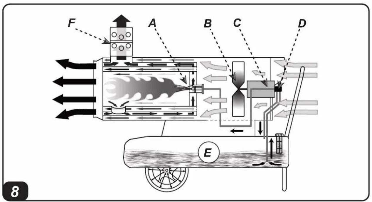
1.DESCRIPTION
This series of heaters is particularly suited to heating medium to large-sized rooms or areas. The series is divided into direct heaters and indirect heaters.
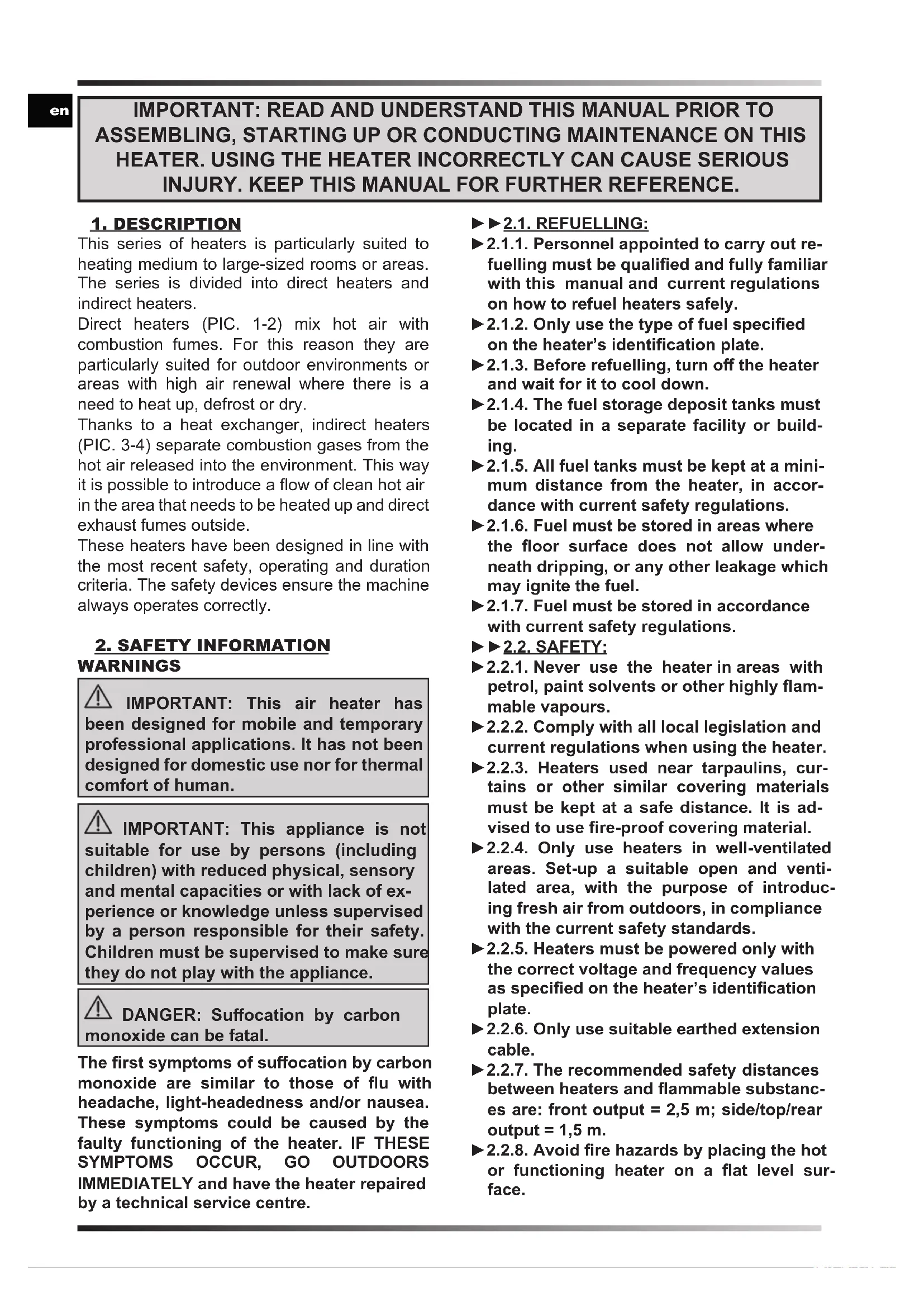
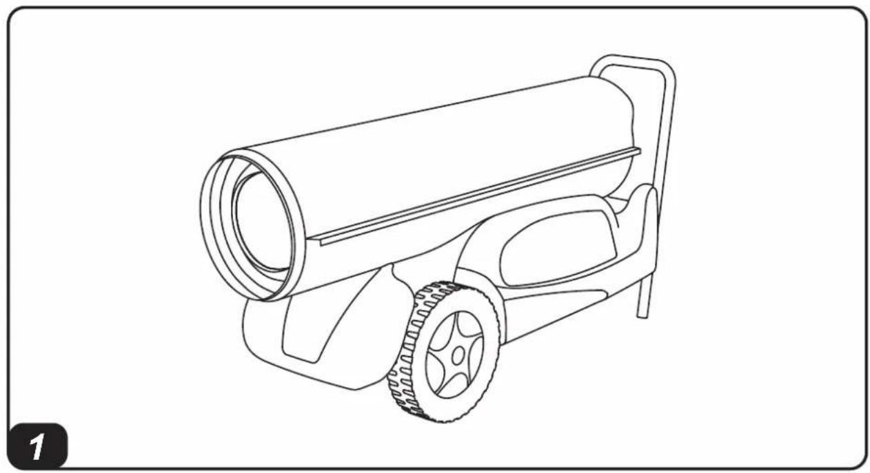
Direct heaters (PIC. 1-2) mix hot air with combustion fumes. For this reason they are particularly suited for outdoor environments or areas with high air renewal where there is a need to heat up, defrost or dry.
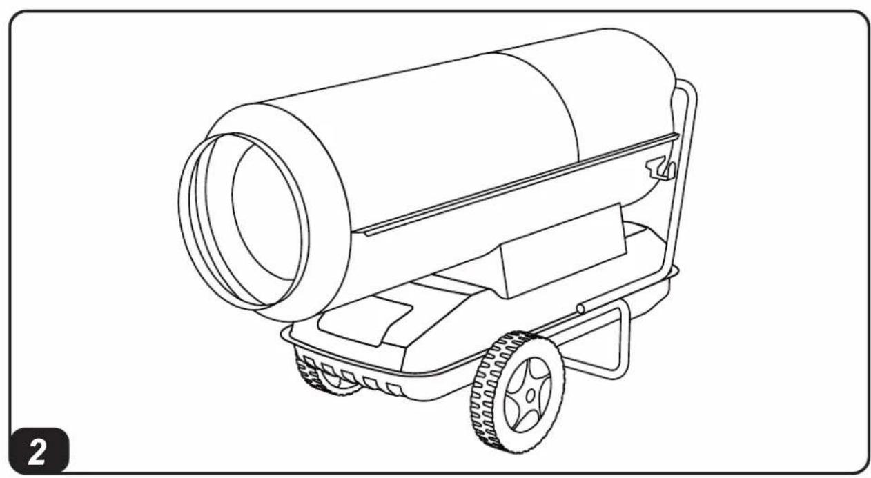
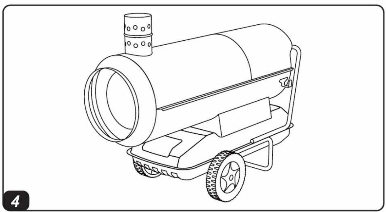
Thanks to a heat exchanger, indirect heaters (PIC. 3-4) separate combustion gases from the hot air released into the environment. This way it is possible to introduce a flow of clean hot air in the area that needs to be heated up and direct exhaust fumes outside.
These heaters have been designed in line with the most recent safety, operating and duration criteria. The safety devices ensure the machine always operates correctly.
2. SAFETY INFORMATION Warnings
IMPORTANT: This air heater has been designed for mobile and temporary professional applications. It has not been designed for domestic use nor for thermal comfort of human.
IMPORTANT: This appliance is not suitable for use by persons (including children) with reduced physical, sensory and mental capacities or with lack of experience or knowledge unless supervised by a person responsible for their safety. Children must be supervised to make sure they do not play with the appliance.
DANGER: Suffocation by carbon monoxide can be fatal.
The first symptoms of suffocation by carbon monoxide are similar to those of flu with headache, light-headedness and/or nausea. These symptoms could be caused by the faulty functioning of the heater. IF THESE SYMPTOMS OCCUR, GO OUTDOORS IMMEDIATELY and have the heater repaired by a technical service centre.
2.1. REFUELLING:
2.1.1. Personnel appointed to carry out refuelling must be qualified and fully familiar with this manual and current regulations on how to refuel heaters safely.
2.1.2. Only use the type of fuel specified on the heater's identification plate.
2.1.3.Before refuelling, turn off the heater and wait for it to cool down.
2.1.4. The fuel storage deposit tanks must be located in a separate facility or building.
2.1.5. All fuel tanks must be kept at a minimum distance from the heater, in accordance with current safety regulations.
2.1.6. Fuel must be stored in areas where the floor surface does not allow underneath dripping, or any other leakage which may ignite the fuel.
2.1.7. Fuel must be stored in accordance with current safety regulations.
2.2.SAFETY:
2.2.1. Never use the heater in areas with petrol, paint solvents or other highly flammable vapours.
2.2.2. Comply with all local legislation and current regulations when using the heater.
▶2.2.3. Heaters used near tarpaulins, curtains or other similar covering materials must be kept at a safe distance. It is advised to use fire-proof covering material.
2.2.4. Only use heaters in well-ventilated areas. Set-up a suitable open and ventilated area, with the purpose of introducing fresh air from outdoors, in compliance with the current safety standards.
2.2.5. Heaters must be powered only with the correct voltage and frequency values as specified on the heater's identification plate.
2.2.6. Only use suitable earthed extension cable.
2.2.7. The recommended safety distances between heaters and flammable substances are: front output = 2,5m side/top/rear output = 1,5m
2.2.8. Avoid fire hazards by placing the hot or functioning heater on a flat level surface.
▶2.2.9. Always keep animals at a safe distance.
2.2.10. Disconnect the heater from the main power supply when not in use.
2.2.11. When controlled by a thermostat, the heater can turn on at any time.
2.2.12. Never use the heater in frequently used rooms or in bedrooms.
▶2.2.13. Never block the heater's air inlet (rear) or the air outlet (front).
2.2.14. Never move, handle, refuel or conduct maintenance on the heater when it is hot or when connected to the power supply or when in operation.
2.2.15. Only use original kit/hose to direct air flow (in and out) (where applicable).
2.2.16. Keep heater's hot parts at as safe distance from inflammable materials (including the power supply cable).
2.2.17. If the power supply cable is damaged, it must be replaced by a technical service centre, in order to prevent further risks.
3.UNPACKING
WARNING: The packaging material is not a toy. Keep the plastic bag out of the reach of children; danger of suffocation!
3.1. Remove all packaging materials used to wrap and deliver the heater and dispose them in compliance with current regulations.
3.2 If the heater is placed on a moving platform, make sure it is moved gently.
3.3. Check for any damage that might have happened during transport. If the heater looks damaged, immediately inform the dealer from which it was purchased.
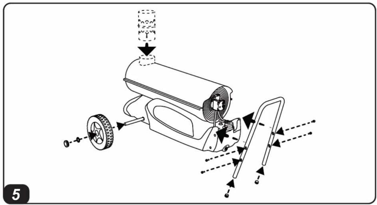
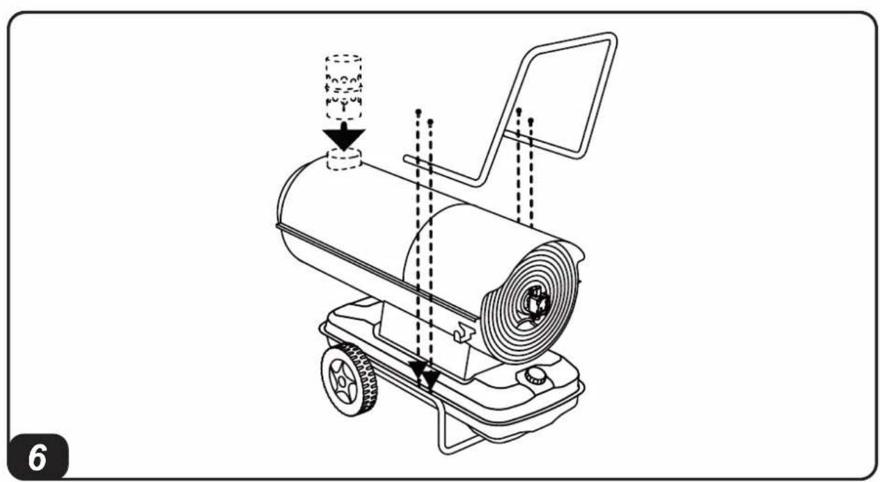
4. ASSEMBLY
These heaters are fitted with wheels, a handle and a chimney depending on the model (PIC. 5-6). These parts, which come with the relative nuts and bolts, are in the heater's packaging.
5. FUEL
WARNING: The heater only works with HVO 100 Biofuel, Diesel B7 or Kerosene.
In order to avoid explosions or any fire hazards, use only diesel or kerosene fuel.
Never use petrol, naphtha, paint solvents, alcohol or any other highly inflammable fuels.
Non-toxic, anti-freeze additives can be used in case of very low temperatures.
It is advisable to use winter diesel below 5^
6. OPERATING PRINCIPLES
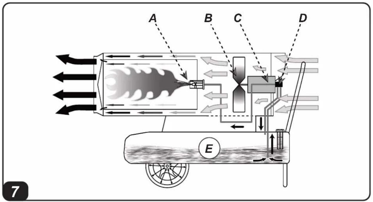
A. Combustion chamber and burner, B. Fan, C. Motor, D. Pump, E. Tank, F. Chimney (indirect models).
The pump draws fuel from the tank and brings it to the operating pressure. The fuel is brought to the nozzle that sprays it into the combustion chamber. The combustion is carried out with a mix of air and fuel and the flow of air generated is pushed outside via the rotation of the fan. In direct models (PIC. 7) combustion products flow together with heated air. In indirect models (PIC. 8) combustion products are directed outside through the chimney. A series of sensors connected to an electronic control board constantly keep the correct operation of the heater monitored and stops the cycle in the event of anomalies.
7. OPERATION
WARNING: Carefully read the "SAFETY INFORMATION" before switching on the heater.
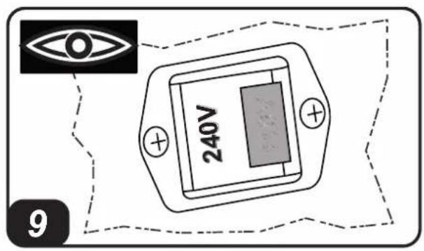
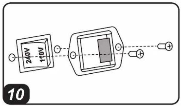
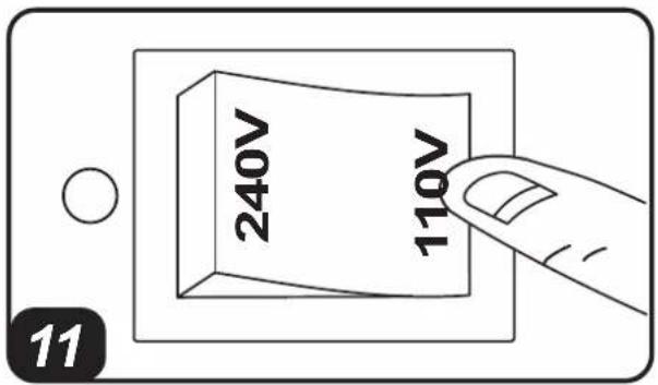
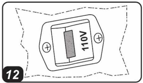
IMPORTANT: In models with dual voltage (...DV), check the position of the dual voltage switch (220-240V / 110-120V) (PIC. 9). If the voltage set on the heater does not correspond to the mains supplied voltage, it is necessary to adjust it. Unscrew the two securing screws of the cover (PIC. 10), adjust/press the switch to the correct voltage (PIC. 11) and reassemble the cover (PIC. 12).
VERIFY THE CONGRUENCE BETWEEN POWER TENSION SUPPLY, SETTING OF DUAL VOLTAGE SWITCH AND TYPE OF PLUG, BECAUSE IMPROPER USE MAY CAUSE DAMAGE TO THE HEATER.
7.1.SWITCHING ON THE HEATER:
7.1.1 . Please follow the safety instructions.
7.1.2. Check if there is enough fuel in the tank.
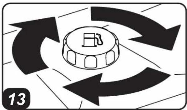
7.1.3.Close the tank cup (PIC. 13).
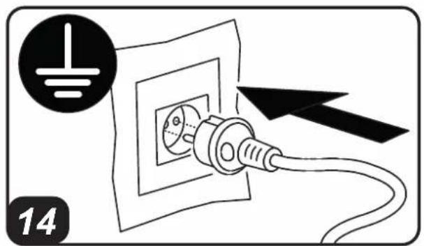
7.1.4. Connect the power supply plug to the mains electricity (PIC. 14) (SEE VOLTAGE IN THE "TECHNICAL DATA TABLE").
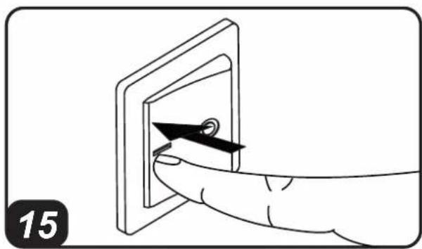
7.1.5. Set the "I/0" switch to "I" (PIC. 15). The heater should turn on within a few seconds. If the heater does not start, refer to paragraph "12. TROUBLESHOOTING".
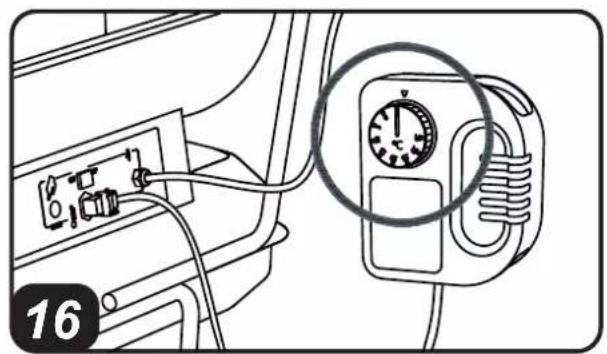
7.1.6. For models with a room thermostat, check the position of the knob (PIC. 16).
PLEASE NOTE: IF THE HEATER SWITCHES OFF DUE TO LACK OF FUEL, TOP UP THE
TANK AND RESET THE HEATER (SEE PAR. 7.2.).
IMPORTANT: In indirect models, combustion products are directed outside through suitable chimney. CARRY OUT THE CHIMNEY IN ACCORDANCE WITH CURRENT SAFETY REGULATIONS AND FOLLOW THE INSTRUCTIONS IN THE RELEVANT SECTION OF THE MANUAL.
7.2. RESETTING THE HEATER:
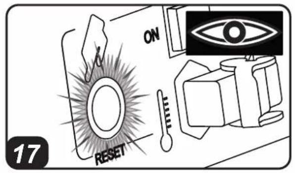
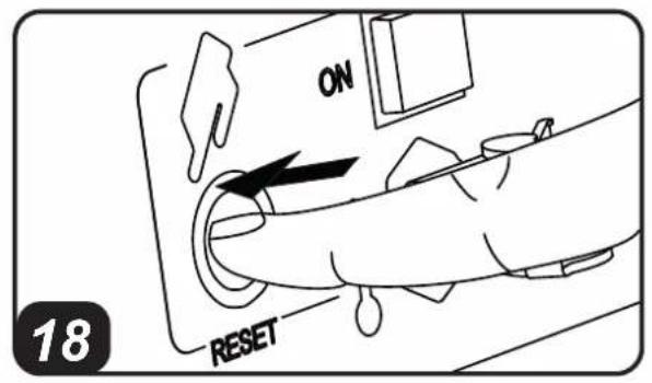
The appliance stops when an anomaly occurs. The reset button turns on with a steady red light (PIC. 17), it means the heater needs to be reset. To reset the heater, press the reset button all the way down (PIC. 18). Identify and remove the cause that stopped the appliance (for instance, obstruction of air intake and/or outlet, total block of the fan, etc.). Please contact an appointed service center for assistance in case it is impossible to solve the problem.
7.3.SWITCHING OFF THE HEATER:
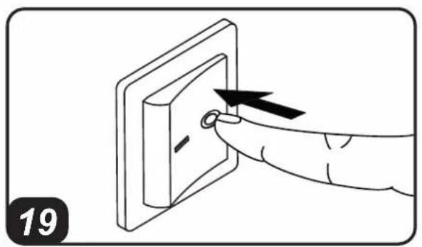
Set the "I/O" button to "0" (PIC. 19). Flames extinguish and the fan keeps on working until the combustion chamber has fully cooled down. Do not pull the plug out until the cooling cycle has totally ended.
8. CLEANING THE FILTERS
THE FILTERS MAY NEED TO BE CLEANED DEPENDING ON THE QUALITY OF THE FUEL USED.
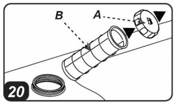
8.1. FUEL TANK FILTER (PIC.20):
8.1.1. Remove tank (A) cap.
8.1.2. Take out the filter (B) from the tank.
8.1.3. Clean the filter (B) with clean fuel, without damaging it.
8.1.4. Put the filter (B) back in the tank.
8.1.5.Close cap (A).
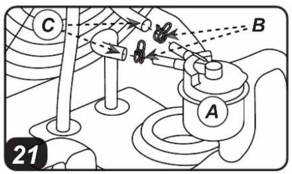
8.2 INTAKE FILTER, (PIC. 21) DEPENDING ON THE MODEL:
8.2.1. Take out the filter (A).
8.2.2. Remove the pipe-clamping straps (B).
8.2.3. Take out the pipes (C).
8.2.4. Replace the filter (A) with an original spare part.
8.2.5. Put the pipes (C) back.
8.2.6. Put the pipe-clamping straps (B) back.
8.2.7. Put the filter (A) back into its original position.
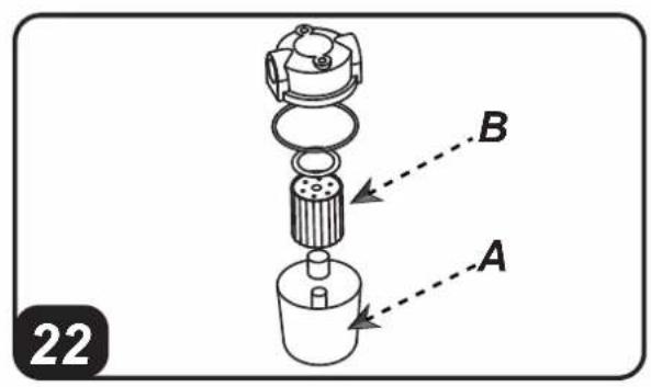
8.3. INTAKE FILTER, (PIC. 22) DEPENDING ON THE MODEL:
8.3.1. Remove the cup (A).
8.3.2. Take out the filter (B) from the cup. Keep gaskets for later use.
8.3.3. Clean the filter (B) with clean fuel, without damaging it.
8.3.4. Put the filter (B) back in the cup.
8.3.5. Put the glass (A) back on and reassemble the gaskets correctly.
8.4. FUEL PUMP FILTER:
See the preventive maintenance schedule.
9. STORAGE AND TRANSPORT
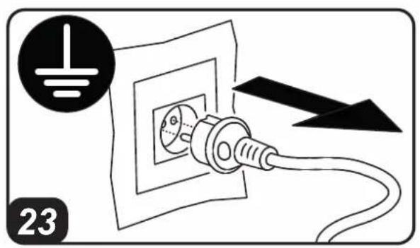
WARNING: Before moving the appliance, the heater must be stopped (SEE PAR. 7.3.) and disconnected from the power supply by pulling out the plug (PIC. 23), wait for a complete cool down and close the tank cap properly to prevent fuel leakage. Keep the heater in horizontal and stable position during transport.
IN ORDER TO KEEP THE HEATER IN THE BEST POSSIBLE CONDITIONS, WE RECOMMEND TO FOLLOW THE BELOW PROCEDURE:
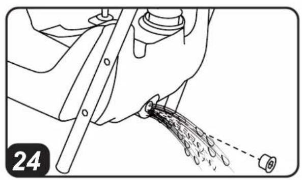
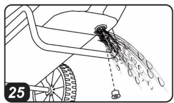
9.1 Empty the fuel by removing the drain cap at the bottom of the tank (PIC.24-25). Dispose the fuel in an appropriate container in accordance with the current safety regulations.
9.2. To remove any residual remaining, pour clean fuel and rinse the tank again.
9.3 Close the drain cap and the tank cap.
9.4. In order to keep the heater in the best possible conditions, we recommend placing it in a dry and safe place.
10. CONNECTING THE ROOM THERMOSTAT
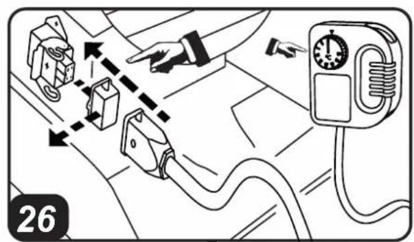
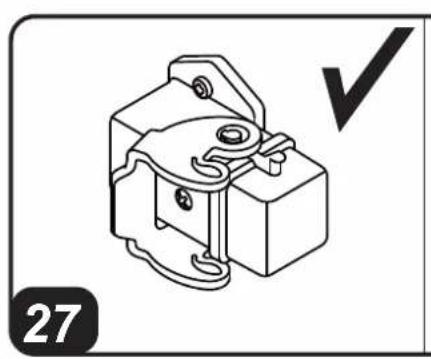
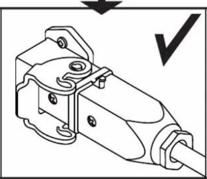
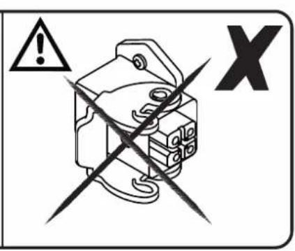
In models with a thermostat connection, remove the cap connected to the appliance and connect the room thermostat (optional) (SEE PIC. 26-27).
11. PREVENTIVE MAINTENANCE SCHEDULE
| COMPONENT MAINTENANCE FREQUENCY MAINTENANCE PROCEDURE | ||
| Fuel tank Clean once a year or as required Empty and rinse the tank with clean fuel (SEE PAR. 9.) | ||
| Filters Clean or replace once a year or as required (make sure they are intact) | Clean the filters (SEE PAR. 8.) | |
| Fuel pump filter Clean or replace once a year or as required (make sure they are intact) | Contact a service centre | |
| Electrodes Clean as required Contact a service centre | ||
| Fan Clean as required Contact a service centre | ||
| Combustion chamber Clean as required Contact a service centre | ||
12. TROUBLESHOOTING
| PROBLEM | POSSIBLE CAUSE POSSIBLE SOLUTION | |
| The heater does not start or does not operate | 1. Starter switch in “OFF” (0) position | 1. Set starter switch to “ON” (I) position (PIC. 15) |
| 2. No power supply | 2a. Insert the power plug into the mains socket correctly (PIC. 14) | |
| 2b. Check voltage of your electric supply system | ||
| 2c. In dual voltage models (...DV) (PIC. 9), set the switch to the correct voltage position required | ||
| 3. Power supply cable interrupted | 3. Contact a service centre | |
| 4. Electronic control board blocked or malfunctioning | 4a. Reset the heater (SEE PAR. 7.2.) | |
| 4b. Contact a service centre | ||
| 4c. Contact a service centre | ||
| 5. Incorrect setting of the room thermostat (if present) | 5. Set the room thermostat to a temperature higher than the working environment temperature (PIC. 16) | |
| 6. No fuel | 6. Top up fuel and reset heater | |
| 7. External substances or dirt in the fuel circuit | 7a. Empty, rinse and refill the tank | |
| 7b. Rinse the filters (SEE PAR. 8.) | ||
| 7c. Contact a service centre | ||
| Smoke while operating | 1. External substances or dirt in the fuel circuit | 1a. Empty and refill the tank with clean fuel |
| 1b. Rinse fuel filters | ||
| 1c. Contact a service centre | ||
| 2. Obstructed inlet air vent | 2. Remove all air vent obstructions | |
| The heater does not turn off | 1. Faulty electronic system 1. Contact a service centre | |
IMPORTANTE: LEGGERE E COMPRENDERE QUESTO MANUALE OPERativo PRIMA DI EFFETTUARE L'ASSEMBLAGGIO, LA MESSA IN FUNZIONE O LA MANUTENZIONE DI QUESTO RISCALDATORE. L'uso ERRATO DEL RISCALDATORE PUO CAUSARE LESIONI GRAVI O FATALI. CONSERVARE QUESTO MANUALE A TITOLO DI FUTURO RIFERIMENTO.
1.DESCrizIONE
7.1.ACCENSIONEL RISCALDATORE:
OMGEVINGSTHERMOSTAAT
O6orpeBaTeN npMOro HarpeBa (PNC. 1-2)
CMEUBAIOT TROPYN BO3dyxC napamn npoDyKTAMN CROPAHNA. IOnTOMy OHN ppeHa3NaueHb IIN pa60TbI CHAPXNI INB NOMeHINx C BbICOKIM yPOBHEM BO3dyXoo6MeHa, rDe eCTb Heo6xoJMoCTb o6OrpeBa, pa3MOPo3KN nn cyuKn.
ObopeBaTeHn HnnpMOro HarpeBa (PNC. 3-4),
6bnarap TaennooMeHHky, No3BOJnOT OTDeIaTb Ra3bl npOyKtbl CropaHnO rOpyeRO Bo3dyxa, NoctynaoUcero B nOmeueHne. Takm o6pa3OM, B O6orpeBaemoe NOMEuHne NOCTynaET NOTOK YnCTORO rOpyeRO Bo3dyxa, a npOyKtbl CropaHnBbBOJrTcH hapyKy.
Данные обorpeВателп pa3pa6оТаны В COOTBEТСТВИСcamыМСOBрЕмEHьIMN КРИТЕРЯМN 6e3ОПаСHOCТи,ФунКцИНэHLбОCTи ИджХСТ.N.3aUITHBIEyCTpoIeCTBa rapaHTnpyIOT npaBUNbHyIO pa6OtyoborpeВателЯ.
2.ИHΦOPMAUЯ OBE3OJACHOCTN IPEyIpeKdEHH

BAXHO: 3TOT BO3dyxoharpeBaTeJb
pa3pa6oTaHДЯMObHoroN BpeMeHHoro npoepccnHaJIbHoro NcNoJIb3OBAHna. OH He npedHa3HaueH HДЯ DomaUHero npmHeHna, Hn DnA Co3dAnHr TEnIbOBOr KOMΦopTa yeNoBeka.

BnKOpNCToByTe HeTOKcNHi DoabKn npOTN 3aMeP3aHHBpa3i DyKe Hn3bKx TempePaTyp.
PekomeHnyetbcBnKOpncTOByBaTn 3mOBe n3eIbHe naNBO npTemnpaTypi HxKYe 5^
6. ПИNHцПИ NOBOTN
A. Kamepa 3ropaHH i naBnK, B. KpunbuaTka, C. DnuryH, D. Hacoc, E. Pe3epByap, F. DmMoBa Tpy6a (moJeni Hnpamoro HarpiBaHH).
Hacoc BCMOKTye naIINBO 3 pe3epByapy,doBOnaNIO TnCK do po6Ouro. PAnIIBo HAdxOanTb y fOpcyHKy, Ika Ioro p03nnlIOE B Kamepi 3ropaHH. TogIHNaBI6yBaetbcra 3abJcKc cymiwi nobITpr/naINBa, a Ioro npOdykTN BHXODaTb Ha3OBHI 3abJcKn NOtOKy NobITpr, CTBOPIOBAHO rKnIbUaTkoIO. Y moDenX npAmoro HarpIBAHNRA (MAJ.7) npOdyKTn rOPIHH noTpapanLIObY cepeoDBuIe 10 obirpaETbcR, B ToI qac kY moDenX HenpAmoro HarpIBAHNRA (MAJ.8) npOdyKTn rOPIHH MOkyTB BiDBoNTbcr y npocTip, 3OBHIHN BIDHOCHO npocToP, 10 obirpaCTbcR, 3a DoNOMOrIO CnCTeMn KaHAI.B.Cepia DaTChIKB, 3eHaHnx 3 eNeKTPoHHIO nLaTOO ynpabInH, 6e3nepePBHO nepeBipae npabInbHicTB po6OTn obirpIBaHa, nepePBauOnu kn Ly pa3i HeNoJaOk.
7. POBOTA
PONEPENXEHH: YBaXHo 03HaNoMTeec3 "IHΦOPMALICIO 3 BE3NEKN", nepu, HIX BBIMKHyTn o6irpiBaq.
BAKJIINBE 3AYBAXEHHY: Y MODEJAX 3 NOBBIHOH HANpyo ...DV),nepebipte NOLOXKeHH nepeMnKaHa HAnpyr (220-240B / 110-120B) (MAJ.9).JaKIO HAnpyra, BnCTaBHeHa O6irpiBaHi, He BiNObiAc HAnpy3i Mepexi, Heo6xIDHO BnCTaBHTn HaJeKHy BeJInuHy. BiKpyTb Dba RbHnT KpInIeHHa KpnKn (MAJ.10), nepemicITb/HaTHcHtB Ha BmNKaHa BeJInuHi HAnpyr, 1O MaC NoDaBaTncsA (MAJ.11)i 3HOBy BCTaHOBiTB KpnKy (MAJ 12).
IOMNIKOBE CHN HENPABUNbHE BCTAHOBJIeHHI NAPAMETPIB HANPYrMOXKe IPN3BECTN DO CEPNo3HNX IOsKOJKeHbOBIPIBAuA.
▶7.1.BMUKAHHOBIGPIBAHA:
7.1.1.BuKoHaIe Bci Bka3iBKn,IO BiHocrTbcra Do 6e3neKn.
7.1.2. IpepeipTe HABHicTB nannBa B pe3epByapi.
7.1.3. 3akniTe np6ky pe3epByapa (MAJ.13).
7.1.4.ПИДКПЮчITьВИЛКУЖИВLEнHЯdo eJIeKTPNUHoiМерекi(MAI.14)(INB.HANPYV B《TABJIINLITEXHIUHNX DAHNX》)
7.1.5. Npebeiditb Bminkau «I/0» y noJoxeHn «I» (MAI. 15). O6irpiBaMae BKNHOHTncr npotrarom deKibkoX cekyHd. Raio o6irpiBaH He BKnIOuaetbcra, nB naparpaΦ «12. BINRAEHHN PPOBJIEM»
▶7.3. BUMNKAHH NOBIPIBAHA:
IpebeEditb Bmikau «I/O» y noJoxeHHA «O» (MAJI. 19). POnym' 3rache, a BeHTnIaTOp npoDobKInTb po60Ty do nobHoro oxoNoJxehn KaMepn 3roprHH. He BiD'edHyTe XnBHeHHa Do 3aBepWeHHa cNKny oxoNoJxehHH.
8. OuHueHHaΦIbTPIB
BNUKOPNCTOBYBAHORI NAJINBA MOXE 3HAIOBNTUCR OUYUENHHAΦINbTPIB:
VOR REPARATUREN RADER AM

WHEELS POSITION 1 - POSIZIONE RUOTE 1 ROUES EN POSITION 1 - RÄDERSTELLUNG 1
Easy movement with empty or half load tank. This position will allow any kind of maintenance. Not suitable for substantial movement with full load tank.
1. Questa posizione permette un facile sped
serbatoio non supera la meta di carico.
Cetie position ouvempertra des mouvements et un entretien racle, meis onllement ait raccions est wite auoiti remoi
Mais seulement sfe reservoir est vide ou a montie rem. Einfache Bewegung mit leerem oder halb vollem Tank.
WHEELS POSITION 2 - POSIZIONE RUOTE 2 - ROUES EN POSITION 1 - RÄDERSTELLUNG 1
Easy movement with full load tank.
Questa posizione permette un facile spostamento se il serbatoio è a
Cette positio
estcompletementrempli.
Einflache Bewegung mit volem Tank.
NOTE:
| CE CONFORMITY CERTIFICATE | CE |
| CE CONFORMITY CERTIFICATE - DICHIARAZIONE DI CONFORMITA CE - EG-KON-FORMITÄTSERKLÄRUNG - DECLARATION DE CONFORMIDAD CE - DECLARATION DE CONFORMITA CE - EG-CONFORMITEITVERKLARING - DECLARATION DE CONFORMIDA-DE CE - EU-OVERENSSTEMMELSESERKLÄERING - EY-VAATIMUSTENMUKAIUSVA-KUUTUS - CE-SAMSVARSERKLÄERING - EG-FÖRSÄKRAN OM ÖVERENSSTÄMMELSE - DEKLARACJA ZGODNOSCI WE - DEKJIAPAUÇIA O COOTBETCTBUNI CE - PROHLÁSENİ O SHODE CE - EK MEGFELELOSEGI NYILATKOZAT - IZJAVA O SKLADNOSTI IN OZNAKA CE - CE UYGUNLUK BEYANI - IZJAVA CE O SUKLINADNOSTI - ES ATITIKTIES DEKLARACIJA - EK ATBILSTIBAS - DEKLARACIJA - EÜ VASTAVUSDEKLARATSIOON -DECLARATIOIE DE CONFORMITATE CE - PREHLAGASE NZE HODE CE - DEKJIAPAUÇIA 3A CßBMECTIMOCT CE - DEKJIAPAUÇIA BIDNOBIDHOCTI CE - IZJAVA CE O PRIKLADNOSTI ΔHAΩΣΗ ΣΥΜΟΡΦΟΣΗ ΕC - CE 符合性声明DANTHERM S.p.A. Via Gardesana 11, -37010- Pastrengo (VR), ITALY | |
| Product: - Produkt: - Produkt: - Produkt: - Produkt: - Produkt: - Produkt: - Produkt: - Produkt: - Produkt: - Produkt: - Produkt: - Produkt: - Produkt: - Produkt: - Produkt: - Produkt: - Produkt: - Produkt: - Produkt: - Produkt: - Produkt: - Produkt: - Produkt: - Produkt: - Produkt: - Produkt: - Produkt: - Produkt: - Produkt: - Produkt: - Produkt: - Produkt: - Produkt: - Produkt : - IZVIJIAO ΣΥΜΟΡΦΟΣΗ ΕC - Product: - Product: - Product: - Product: - Product: - Product: - Product: - Product: - Product: - Product: - Product: - Product: - Product: - Product: - Product: - Product: - Product: - Product: - Product: - Product: - Product: - Product: - Product: - Product: - Product: - Product: - Product: - Product: - Product: - Product: - Product: - Product: - Product: - Product: - B 130 - B 180 - B 230 - B 360 - BV 69E - BV 77E - BV 110E - BV 170E - BV 290E | |
| We declare that it is compliant with: - Si dichiara che è conforme a: - Es wird als konform mit den folgenden Normen erklär: - Se declara que está en conformidad con: - Nous déclarons sa conformité à: - Hierbij worden verklaard dat het product conform is met: - Declara-se que está em conformidade com: - Vi erklær at Produktoi overensstammelse med: - Vakuutetaan olevan yhdenmukainen: - Man erklær at apparatet er i overensstammelse med: - Härmed intygas det att produitär ärendlig med fölljande: - Osciadzca sie, ze jest zgodny z: - 3aЯвсям o cootbetebrn trpebovanma: - Prohlasje se, ze je v souladu s: - Kijelentjuk, hagy a termek megfe- lez alalbbiaknak: - Izpolnjue zahteve: - Aşaqidaki standartlara uygun olduğunu belyan ederiz: - Izjavluje se da je u skladu s: - Pareisiškame, kad atitinka: - Tiek deklarets, ka atbilist: - Käesolevaga deklareeritakse, et toode vastab: - Declaram că este conform urmátoarelor: - Prehlasje sa, ze je v súlade s: - Deckapira ce ye otrobatpá na: - Biñnoviidae bimorgam: - Izjavluje se da je u skladu s: - Δηλώνουμε στι είνα σύμφωνο με: - 兹证明符合:2014/30/EU, 2014/35/EUEN 62233:2008, EN 61000-3-2:2014, EN 61000-3-3:2013, EN 55014-1:2006/A2:2011, EN 55014-2:2015, EN 60335-1:2012/A11:2014, EN 60335-2-102:2016Stefano Verani (Member of the Board) | |
| Pastrengo, 2022 | |
| UKCA CONFORMITY CERTIFICATE | UK CA |
| UKCA CONFORMITY CERTIFICATE DANTHERM S.p.A. Via Gardesana 11, -37010- Pastrengo (VR), ITALY Product: | |
| B 130 - B 180 - B 230 - B 360 - B 230DV - B 360DV - BV 69E - BV 77E - BV 69DV - BV 77DV - BV 110E - BV 170E - BV 290E - BV 110DV - BV 170DV - BV 290DV | |
| We declare that it is compliant with: 2014/30/EU, 2014/35/EU BS EN 62233:2008, BS EN 61000-3-2:2014, BS EN 61000-3-3:2013, BS EN 55014-1:2017+A11:2020, BS EN 55014-2:2015, BS EN 60335- 1:2012+A2:2019, BS EN 60335-2-102:2006+A2:2016 Stefano Verani (Member of the Board) | |
| Pastrengo, 2022 | |
NOTE:
en - DISPOSAL OF THE PRODUCT
-This product has been designed and manufactured with top-quality materials and components, which can be re-cycled and re-used.
-When a crossed-wheely bin symbol is attached to the product, it means that the product is protected by the, 2012/19/UE European Directive.
-Please obtain information regarding the local differentiated collection system for electrical and electronic products.
- Respect local Standards in force and do not dispose of old products as normal domestic waste. Correct disposal of the product helps to prevent possible negative consequences for health, the environment and mankind.
it - SMALTIMENTO DEL PRODOTTO
bg-IMXVBpJIHHEHA YPEDA
-ToBa 3dEJIe e npoeKTIpaHO n npoI3BeDeHO C MaTePnAII N KOMNoHEHTN OT BucOko KaueCTBO, KOITo MOraT da ce pezIKnPaT nnn I3NO3BAT NOBTOPO.
-Korato Ha Haryoe n3dene e noCTabeH c mB0J C 6nIOH Ha KOJIeIa, MapKnpaH C XNKC, TOBa O3HaYaba, Ye n3denneto e 3aUHTeHO cbrnaCHO Ebponeecka DupekTNaBa 2012/19/UE.
-Monla ce HhOpmpate OTHOcH MeCTema 3a pa3dEnHO n3XbBpIHe Ha eJektpnueckn neJektpoHHn n3deJIy.
-Cn3BaIITeINCTBaUNTe MeCTHn HOpMaTINBn INe IN3XbPnIeTe IN3dEJIyTA, 3aEDHO C HopMaJInTE DOMAKINCKN OTNaIDbU. IpaBnIHOTO IN3XBpIaHE Ha IN3dEJIyTA, NOMaRa 3a IN36yRBAHe Ha Bb3MOKHN OTPuCaTeHNO NocJeDnU, 3a 3dpABeTO Ha Xopata IN 3a ONa3BaHe Ha OKoJHaTa CpeDa.
uk-UTNI3ALIIBNPO6Y
-LeBnBn6 6yB cnpoeKToBaHn i BnPo6IeHn 3 BnKOpNCtAHHm BnCOKoRiChnx MaTePiJIb i KOMnJIeKTyIOUHX, RKi MOKyTb 6yTN NOBTOHO nepeo6JIeH i BnKOpNCtAHi.
-Якuto Ha Bupi6 haheceHo cmbon nepekpecneHoro 6aka 3 konecamn dna CmTTra, ue o3hauae, zu Bupi6 Biinobiae DnpekTnbicBponebckoRo Cooy 2012/19/UE.
-Прсимо ознайомпгся 3 iнфорmaцю сидду micueboi cnctemn po3dilbHoro 36opy cmTTя eNeKtpuHoro i eNeKtpoHoro 6bnHaHH.
-DoTpMmYtecb HHHnx MlceBnX npabnI he BnKndaTe capi Bnpo6n do 3BnuaHnx NObyTOBnX BiXdOIB. PpaBnHa yTuNi3aui Bnpo6y donomarae yHKHytn MOkNbNx HeratNBHX HacniikB dner DOkBknI i 3DopOB'JIOdei.
bs-ODLAGANJE PROIZVODA
-Ovaj je proizvod dizainiran i proizveden koristenjem materijala i komponenata visoke kvalitete koji se mogu reciklarati i ponovo koristiti.
Kada se na ovaj proizvod postavi simbol prekrižene kante /obilježene krstom na točkovima, to znači da je proizvod podložan Evropskoj Direktivi 2012/19/UE.
-Molimo Vas da se informirate o lokalnom sistemu diferencijalnog sakupljanja elektrichni i elektronskih proizvoda.
-Postujte lokalne propise na snazi i ne odbacujte stare proizvode u obicni kuçanski opad. Pravilno odlaganje proizvoda pomaže i onemogucuje negativne posljedice za zdravlje ljudi i okolisa
- IMPORTANT: READ AND UNDERSTAND THIS MANUAL PRIOR TO ASSEMBLING, STARTING UP OR CONDUCTING MAINTENANCE ON THIS HEATER. USING THE HEATER INCORRECTLY CAN CAUSE SERIOUS INJURY. KEEP THIS MANUAL FOR FURTHER REFERENCE.
- 1.DESCRIPTION
- SAFETY INFORMATION Warnings
- 3.UNPACKING
- ASSEMBLY
- FUEL
- OPERATING PRINCIPLES
- OPERATION
- 7.1.SWITCHING ON THE HEATER:
- RESETTING THE HEATER:
- 7.3.SWITCHING OFF THE HEATER:
- CLEANING THE FILTERS
- FUEL TANK FILTER (PIC.20):
- INTAKE FILTER, (PIC. 21) DEPENDING ON THE MODEL:
- INTAKE FILTER, (PIC. 22) DEPENDING ON THE MODEL:
- FUEL PUMP FILTER:
- STORAGE AND TRANSPORT
- IN ORDER TO KEEP THE HEATER IN THE BEST POSSIBLE CONDITIONS, WE RECOMMEND TO FOLLOW THE BELOW PROCEDURE:
- CONNECTING THE ROOM THERMOSTAT
- PREVENTIVE MAINTENANCE SCHEDULE
- TROUBLESHOOTING
- IMPORTANTE: LEGGERE E COMPRENDERE QUESTO MANUALE OPERativo PRIMA DI EFFETTUARE L'ASSEMBLAGGIO, LA MESSA IN FUNZIONE O LA MANUTENZIONE DI QUESTO RISCALDATORE. L'uso ERRATO DEL RISCALDATORE PUO CAUSARE LESIONI GRAVI O FATALI. CONSERVARE QUESTO MANUALE A TITOLO DI FUTURO RIFERIMENTO.
- 1.DESCrizIONE
- 7.1.ACCENSIONEL RISCALDATORE:
- OMGEVINGSTHERMOSTAAT
- 2.ИHΦOPMAUЯ OBE3OJACHOCTN IPEyIpeKdEHH
- ПИNHцПИ NOBOTN
- POBOTA
- ▶7.1.BMUKAHHOBIGPIBAHA:
- ▶7.3. BUMNKAHH NOBIPIBAHA:
- OuHueHHaΦIbTPIB
- WHEELS POSITION 1 - POSIZIONE RUOTE 1 ROUES EN POSITION 1 - RÄDERSTELLUNG 1
- WHEELS POSITION 2 - POSIZIONE RUOTE 2 - ROUES EN POSITION 1 - RÄDERSTELLUNG 1
- en - DISPOSAL OF THE PRODUCT
- it - SMALTIMENTO DEL PRODOTTO
- bg-IMXVBpJIHHEHA YPEDA
- uk-UTNI3ALIIBNPO6Y
- bs-ODLAGANJE PROIZVODA
Brand : Master
Model : BV 170
Category : Heating