CG 36DL - Grass trimmer HITACHI - Free user manual and instructions
Find the device manual for free CG 36DL HITACHI in PDF.
| Brand | Hitachi |
| Model | CG 36DL (CG36DL, CG36DL(L), CG36DAL, CG36DAL(L)) |
| Category | String trimmer (brush cutter) |
| Type | Cordless, lithium-ion battery |
| Cutting diameter | 310 mm |
| No-load speed | 5800 - 7000 min⁻¹ (adjustable) |
| Battery | Lithium-ion 36 V (BSL3620 2.0 Ah, BSL3626 or BL36200) |
| Charger | UC36YRSL (14.4 - 36 V) |
| Weight (with head, battery, strap and guard) | 5.5 - 6.0 kg depending on version |
| Runtime | Approximately 35 min (normal) / 15 min (high) with BSL3620 |
| Cutting system | Semi-automatic nylon line head (tap-and-go), optional blade |
| Nylon line length | 4 m, cutting length 90-110 mm |
| Sound power level | 85 dB(A) |
| Sound pressure level | 76 dB(A) |
| Vibration | 4 m/s² (uncertainty K = 1.5 m/s²) |
| Brake | Automatic electric brake (stops in 1-3 seconds) |
| Safety | Locking lever, protective guard, emergency stop |
| Maintenance | External cleaning, checking and replacing carbon brushes |
| Spare parts | Nylon head, blade, carbon brushes, battery, charger |
| Repairability | Hitachi authorized maintenance centers |
| Warranty | Complies with national regulations (excluding misuse) |
Frequently Asked Questions - CG 36DL HITACHI
User questions about CG 36DL HITACHI
0 question about this device. Answer the ones you know or ask your own.
Ask a new question about this device
Download the instructions for your Grass trimmer in PDF format for free! Find your manual CG 36DL - HITACHI and take your electronic device back in hand. On this page are published all the documents necessary for the use of your device. CG 36DL by HITACHI.
USER MANUAL CG 36DL HITACHI
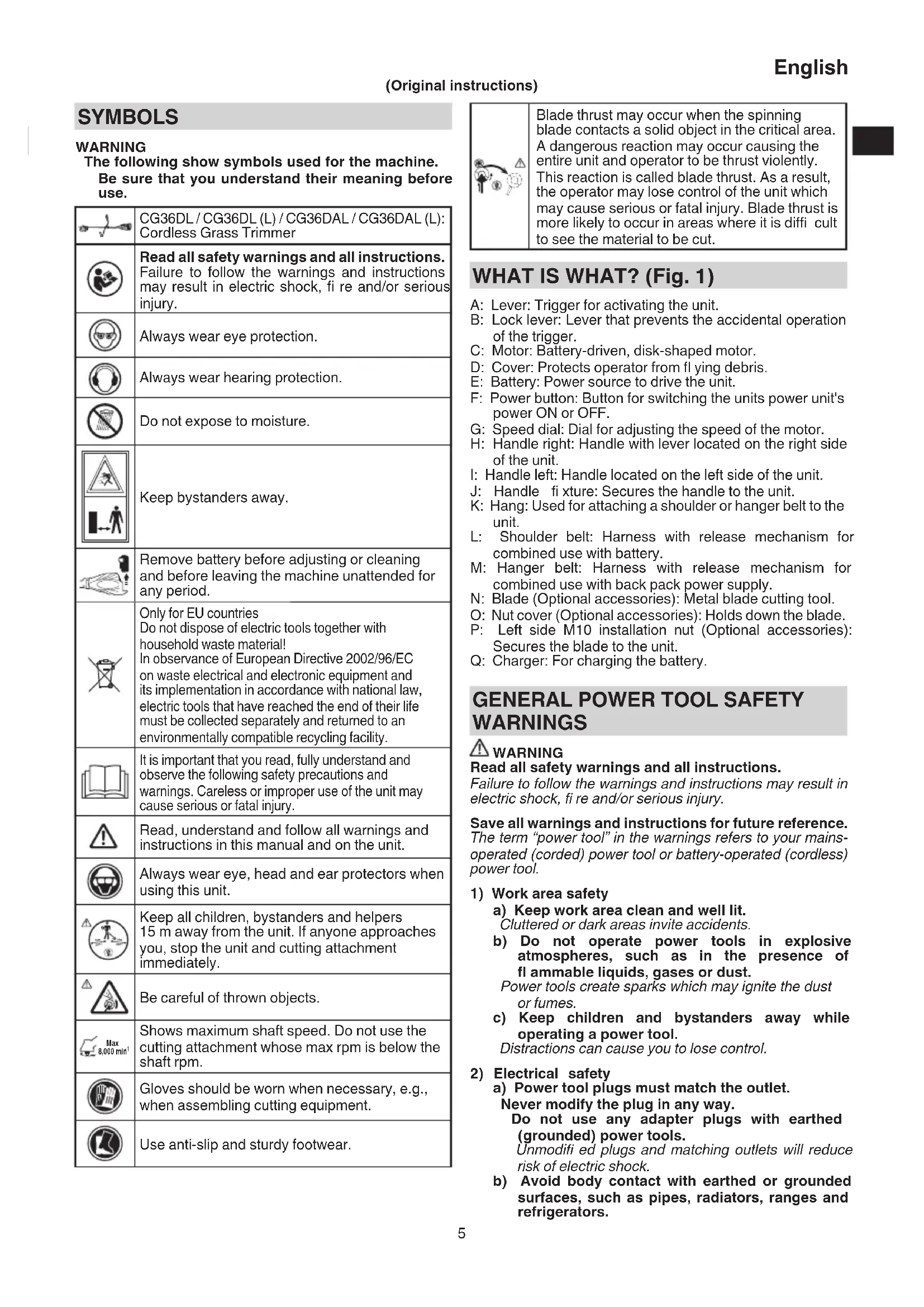
The following show symbols used for the machine. Be sure that you understand their meaning before use.
| CG36DL / CG36DL (L) / CG36DAL / CG36DAL (L): Cordless Grass Trimmer | |
| Read all safety warnings and all instructions. Failure to follow the warnings and instructions may result in electric shock, fire and/or serious injury. | |
| Always wear eye protection. | |
| Always wear hearing protection. | |
| Do not expose to moisture. | |
| Keep bystanders away. | |
| Remove battery before adjusting or cleaning and before leaving the machine unattended for any period. | |
| Only for EU countries Do not dispose of electric tools together with household waste material! In observance of European Directive 2002/96/EC on waste electrical and electronic equipment and its implementation in accordance with national law, electric tools that have reached the end of their life must be collected separately and returned to an environmentally compatible recycling facility. | |
| It is important that you read, fully understand and observe the following safety precautions and warnings. Careless or improper use of the unit may cause serious or fatal injury. | |
| Read, understand and follow all warnings and instructions in this manual and on the unit. | |
| Always wear eye, head and ear protectors when using this unit. | |
| Keep all children, bystanders and helpers 15 m away from the unit. If anyone approaches you, stop the unit and cutting attachment immediately. | |
| Be careful of thrown objects. | |
| Max 8,000 min- | Shows maximum shaft speed. Do not use the cutting attachment whose max rpm is below the shaft rpm. |
| Gloves should be worn when necessary, e.g., when assembling cutting equipment. | |
| Use anti-slip and sturdy footwear. |
Blade thrust may occur when the spinning blade contacts a solid object in the critical area. A dangerous reaction may occur causing the entire unit and operator to be thrust violently. This reaction is called blade thrust. As a result, the operator may lose control of the unit which may cause serious or fatal injury. Blade thrust is more likely to occur in areas where it is difficult to see the material to be cut.
WHAT IS WHAT? (Fig. 1)
A: Lever: Trigger for activating the unit.
B: Lock lever: Lever that prevents the accidental operation of the trigger.
C: Motor: Battery-driven, disk-shaped motor.
D: Cover: Protects operator from flying debris.
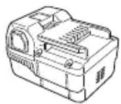
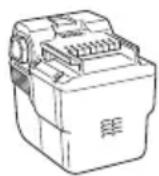
E: Battery: Power source to drive the unit.
F: Power button: Button for switching the units power unit's power ON or OFF.
G: Speed dial; Dial for adjusting the speed of the motor.
H: Handle right: Handle with lever located on the right side of the unit.
I: Handle left: Handle located on the left side of the unit.
J: Handle fi xture: Secures the handle to the unit.
K: Hang: Used for attaching a shoulder or hanger belt to the unit.
L: Shoulder belt: Harness with release mechanism for combined use with battery.
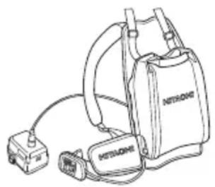
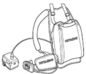
M: Hanger belt: Harness with release mechanism for combined use with back pack power supply.
N: Blade (Optional accessories): Metal blade cutting tool.
O: Nut cover (Optional accessories): Holds down the blade.
P: Left side M10 installation nut (Optional accessories): Secures the blade to the unit.
Q: Charger: For charging the battery.
GENERAL POWER TOOL SAFETY WARNINGS
WARNING
Read all safety warnings and all instructions.
Failure to follow the warnings and instructions may result in electric shock, fire and/or serious injury.
Save all warnings and instructions for future reference. The term "power tool" in the warnings refers to your mains-operated (cored) power tool or battery-operated (cordless) power tool.
1) Work area safety
a) Keep work area clean and well lit. Cluttered or dark areas invite accidents
b) Do not operate power tools in explosive atmospheres, such as in the presence of flammable liquids, gases or dust.
Power tools create sparks which may ignite the dust or fumes.
c) Keep children and bystanders away while operating a power tool.
Distractions can cause you to lose control.
2) Electrical safety
a) Power tool plugs must match the outlet.
Never modify the plug in any way.
Do not use any adapter plugs with earthed (grounded) power tools.
Unmodified plugs and matching outlets will reduce risk of electric shock.
b) Avoid body contact with earthed or grounded surfaces, such as pipes, radiators, ranges and refrigerators.
English
There is an increased risk of electric shock if your body is earthed or grounded.
c) Do not expose power tools to rain or wet conditions.
Water entering a power tool will increase the risk of electric shock.
d) Do not abuse the cord. Never use the cord for carrying, pulling or unplugging the power tool.
Keep cord away from heat, oil, sharp edges or moving parts.
Damaged or entangled cords increase the risk of electric shock.
e) When operating a power tool outdoors, use an extension cord suitable for outdoor use.
Use of a cord suitable for outdoor use reduces the risk of electric shock.
f) If operating a power tool in a damp location is unavoidable, use a residual current device (RCD) protected supply.
Use of an RCD reduces the risk of electric shock.
3) Personal safety
a) Stay alert, watch what you are doing and use common sense when operating a power tool. Do not use a power tool while you are tired or under the influence of drugs, alcohol or medication.
A moment of inattention while operating power tools may result in serious personal injury.
b) Use personal protective equipment. Always wear eye protection.
Protective equipment such as dust mask, non-skid safety shoes, hard hat, or hearing protection used for appropriate conditions will reduce personal injuries.
c) Prevent unintentional starting. Ensure the switch is in the off position before connecting to power source and/or battery pack, picking up or carrying the tool.
Carrying power tools with your finger on the switch or energising power tools that have the switch on invites accidents.
d) Remove any adjusting key or wrench before turning the power tool on.
A wrench or a key left attached to a rotating part of the power tool may result in personal injury.
e) Do not overreach. Keep proper footing and balance at all times.
This enables better control of the power tool in unexpected situations.
f) Dress properly. Do not wear loose clothing or jewellery. Keep your hair, clothing and gloves away from moving parts.
Loose clothes, jewellery or long hair can be caught in moving parts.
g) If devices are provided for the connection of dust extraction and collection facilities, ensure these are connected and properly used.
Use of dust collection can reduce dust related hazards.
4) Power tool use and care
a) Do not force the power tool. Use the correct power tool for your application.
The correct power tool will do the job better and safer at the rate for which it was designed.
b) Do not use the power tool if the switch does not turn it on and off.
Any power tool that cannot be controlled with the switch is dangerous and must be repaired.
c) Disconnect the plug from the power source and/ or the battery pack from the power tool before making any adjustments, changing accessories, or storing power tools.
Such preventive safety measures reduce the risk of starting the power tool accidentally.
d) Store idle power tools out of the reach of children and do not allow persons unfamiliar with the power tool or these instructions to operate the power tool.
Power tools are dangerous in the hands of untrained users.
e) Maintain power tools. Check for misalignment or binding of moving parts, breakage of parts and any other condition that may affect the power tool's operation.
If damaged, have the power tool repaired before use.
Many accidents are caused by poorly maintained power tools.
f) Keep cutting tools sharp and clean.
Properly maintained cutting tools with sharp cutting edges are less likely to bind and are easier to control.
g) Use the power tool, accessories and tool bits etc. in accordance with these instructions, taking into account the working conditions and the work to be performed.
Use of the power tool for operations different from those intended could result in a hazardous situation.
5) Battery tool use and care
a) Recharge only with the charger specified by the manufacturer.
A charger that is suitable for one type of battery pack may create a risk of fire when used with another battery pack.
b) Use power tools only with specifically designated battery packs.
Use of any other battery packs may create a risk of injury and fire.
c) When battery pack is not in use, keep it away from other metal objects, like paper clips, coins, keys, nails, screws or other small metal objects, that can make a connection from one terminal to another.
Shorting the battery terminals together may cause burns or a fire.
d) Under abusive conditions, liquid may be ejected from the battery; avoid contact. If contact accidentally occurs, fl ush with water. If liquid contacts eyes, additionally seek medical help.
Liquid ejected from the battery may cause irritation or burns.
6) Service
a) Have your power tool serviced by a qualified repair person using only identical replacement parts.
This will ensure that the safety of the power tool is maintained.
PRECAUTION
Keep children and infirm persons away.
When not in use, tools should be stored out of reach of children and infirm persons.
GRASS TRIMMER SAFETY WARNINGS
IMPORTANT
READ CAREFULLY BEFORE USE KEEP FOR FUTURE REFERENCE
Safe operation practices
- Training
a) Read the instructions carefully. Be familiar with the controls and the correct use of the machine.
b) Never allow people unfamiliar with these instructions or children to use the machine. Local regulations can restrict the age of the operator.
c) Keep in mind that the operator or user is responsible for accidents or hazards occurring to other people or their property.
Preparation
a) Before use check the supply and extension cord for signs of damage or aging. If the cord becomes damaged during use, disconnect the cord from the supply immediately.
DO NOT TOUCH THE CORD BEFORE DISCONNECTING THE SUPPLY.
Do not use the machine if the cord is damaged or worn.
b) Before use, always visually inspect the machine for damaged, missing or misplaced guards or shields.
c) Never operate the machine while people, especially children, or pets are nearby.
d) Never replace nylon head with metallic cutting means.
Operation
a) Wear eye protection, stout shoes and long trousers at all times while operating the machine.
b) Avoid using the machine in bad weather conditions, especially when there is a risk of lightning.
c) Use the machine only in daylight or good artificial light.
d) Never operate the machine with damaged guards or shields or without guards or shields in place.
e) Switch on the motor only when the hands and feet are away from the cutting means.
f) Always disconnect the machine from the power supply (i.e. remove the plug from the mains or remove the disabling device)
- whenever the machine is left unattended;
- before clearing a blockage;
- before checking, cleaning or working on the machine;
- after striking a foreign object;
- whenever the machine starts vibrating abnormally.
g) Take care against injury to feet and hands from the cutting means.
h) Always ensure that the ventilation openings are kept clear of debris.
i) Never modify the unit/machine in any way. Do not use your unit/machine for any job except that for which it is intended.
- Maintenance, transport and storage
a) Disconnect the machine from the power supply (i.e. remove the plug from the mains or remove the disabling device) before carrying out maintenance or cleaning work.
b) Use only the manufacturer's recommended replacement parts and accessories.
c) Inspect and maintain the machine regularly. Have the machine repaired only by an authorized repairer.
d) When not in use, store the machine out of the reach of children.
e) When transporting in a vehicle or storage, cover blade with blade cover.
PRECAUTIONS FOR CORDLESS GRASS TRIMMER
WARNING
- Exercise patience in all work with the tool. And dress properly to keep warm.
- Plan all work ahead to prevent accidents.
- Do not operate the tool at night or under bad weather conditions when visibility is poor. And do not operate the tool when it is raining or right after it has been raining.
Working on slippery ground could lead to an accident if you lose your balance.
- Inspect the nylon head before starting work.
Do not use the tool if the nylon head is cracked, scarred or bent.
Make sure the nylon head is properly attached. A nylon head that falls apart or comes loose during operation could cause an accident.
- Be sure to attach the cover before starting work.
Operating the tool without this parts could lead to injury.
- Be sure to attach the loop handle before starting work. Make sure it is not loose but properly attached before starting work. Hold the loop handle firmly during work and do not swing the tool around, but use the correct posture and maintain your balance.
Losing your balance during work could lead to an injury.
- Take care when starting the motor.
Place the tool on level ground.
Do not operate the tool within 15m of people or animals.
Make sure that the nylon head does not come into contact with the ground or trees and plants.
A careless start could lead to injury.
-
Do not secure the lock lever.
-
Accidentally pulling back the lever could lead to unexpected injury.
-
Before leaving the tool, press the power button to turn it off.
-
Operate the tool with care near electric cables, gas pipes and similar installations.
-
Look out for and remove empty cans, wire, stones or other obstacles before starting work. And do not work near tree roots or rocks.
Working in such areas could damage the nylon head or lead to injury.
- Never touch the nylon head during operation.
Also make sure it does not come into contact with your hair, clothes, etc.
- In the following situations, turn off the motor and check that the nylon head has stopped rotating.
To move to another work area.
To remove rubbish or grass that has become stuck in the tool.
To remove from the work area obstacles or the rubbish, grass and chips generated by trimming.
To lay down the tool
Doing this with the nylon head still rotating could lead to unexpected accidents.
- Do not use the tool within 15m of another person.
When you work with someone else, maintain a distance of more than 15m
Flying chips could lead to unexpected accidents.
When working on unstable surfaces like slopes, make sure that your co-worker is not exposed to any hazards. Use whistles or other means for calling the attention of your co-workers.
- When grass and other objects become entangled in the nylon head, turn off the motor and make sure the nylon head has stopped rotating before removing them.
Removing objects from the nylon head when it is still rotating will lead to injury.
Continuing operation when foreign matter is stuck in the nylon head may lead to damage.
English
- If the tool is operating poorly and produces strange noise or vibrations, turn off the motor immediately and ask your dealer to have it inspected and repaired.
Continued use under these conditions could lead to injury or tool damage.
- If you drop or bump the tool, inspect it carefully to check there is no damage, cracks or deformation.
Using a tool that is damaged, cracked or deformed could result in injury.
- Secure the tool during vehicle transport to ensure that it lies still.
Failure to heed this warning may result in an accident.
- This product contains a strong permanent magnet in the motor.
Observe the following precautions regarding adhering of chips to the tool and the effect of the permanent magnet on electronic devices.
CAUTION
- Do not place the tool on a workbench or work area where metal chips are present.
The chips may adhere to the tool, resulting in injury or malfunction.
If chips have adhered to the tool, do not touch it. Remove the chips with a brush.
Failure to do so may result in injury.
If you use a pacemaker or other electronic medical device, do not operate or approach the tool.
Operation of the electronic device may be affected.
Do not use the tool in the vicinity of precision devices such as cell phones, magnetic cards or electronic memory media.
Doing so may lead to misoperation, malfunction or loss of data.
CAUTION
-
Do not turn on the nylon head for cutting objects other than grass. Do not operate the tool in water puddles and make sure that soil does not come into contact with the nylon head.
-
The tool contains precision parts and should not be dropped, exposed to strong impact or water.
The tool could be damaged or malfunction.
-
When the tool is to be stored after use or be transported, remove the nylon head.
-
Do not expose the tool to insecticide and other chemicals. Such chemicals could cause cracking and other damage.
-
Replace warning labels with new labels when they become difficult to recognize or illegible and when they start to peel.
Ask your dealer to provide the warning labels.
- Do not touch the motor immediately after use since it may be very hot.
PRECAUTIONS FOR BATTERY AND CHARGER
-
Always charge the battery at a temperature of 0^- 40^ A temperature of less than 0^ will result in over charging which is dangerous. The battery cannot be charged at a temperature higher than 40^ The most suitable temperature for charging is that of 20^ - 25^
-
When one charging is completed, leave the charger for about 15 minutes before the next charging of battery.
Do not charge more than two batteries consecutively.
-
Do not allow foreign matter to enter the hole for connecting the rechargeable battery.
-
Do not insert object into the air ventilation slots of the charger. Inserting metal objects or inflammables into the charger air ventilation slots will result in electrical shock hazard or damaged charger.
-
Using an exhausted battery will damage the charger.
- Bring the battery to the shop from which it was purchased as soon as the post-charging battery life becomes too short for practical use. Do not dispose of the exhausted battery.
- Never disassemble the rechargeable battery and charger.
- Never short-circuit the rechargeable battery. Short-circuiting the battery will cause a great electric current and overheat. It results in burn or damage to the battery.
- Do not dispose of the battery in fire. If the battery is burnt, it may explode.
CAUTION ON LITHIUM-ION BATTERY
To extend the lifetime, the lithium-ion battery equips with the protection function to stop the output.
In the cases of 1 to 3 described below, when using this product, even if you are pulling the switch, the motor may stop. This is not the trouble but the result of protection function.
- When the battery power remaining runs out, the motor stops.
In such case, charge it up immediately. - If the tool is overloaded, the motor may stop. In this case, release the switch of tool and eliminate causes of overloading. After that, you can use it again.
- If the battery is overheated under overload work, the battery power may stop.
In this case, stop using the battery and let the battery cool. After that, you can use it again.
Furthermore, please heed the following warning and caution.
In order to prevent any battery leakage, heat generation, smoke emission, explosion and ignition beforehand, please be sure to heed the following precautions.
- Make sure that swarf and dust do not collect on the battery.
During work make sure that swarf and dust do not fall on the battery. - Make sure that any swarf and dust falling on the power tool during work do not collect on the battery.
- Do not store an unused battery in a location exposed to swarm and dust.
Before storing a battery, remove any swarf and dust that may adhere to it and do not store it together with metal parts (screws, nails, etc.). - Do not pierce battery with a sharp object such as a nail, strike with a hammer, step on, throw or subject the battery to severe physical shock.
- Do not use an apparently damaged or deformed battery.
- Do not use the battery in reverse polarity.
- Do not connect directly to an electrical outlets or car cigarette lighter sockets.
- Do not use the battery for a purpose other than those specified.
- If the battery charging fails to complete even when a specified recharging time has elapsed, immediately stop further recharging.
- Do not put or subject the battery to high temperatures or high pressure such as into a microwave oven, dryer, or high pressure container.
- Keep away from fire immediately when leakage or foul odor are detected.
- Do not use in a location where strong static electricity generates.
- If there is battery leakage, foul odor, heat generated, discolored or deformed, or in any way appears abnormal during use, recharging or storage, immediately remove it from the equipment or battery charger, and stop use.
CAUTION
- If liquid leaking from the battery gets into your eyes, do not rub your eyes and wash them well with fresh clean water such as tap water and contact a doctor immediately.
If left untreated, the liquid may cause eye-problems.
- If liquid leaks onto your skin or clothes, wash well with clean water such as tap water immediately.
There is a possibility that this can cause skin irritation.
- If you find rust, foul odor, overheating, discolor, deformation, and/or other irregularities when using the battery for the first time, do not use and return it to your supplier or vendor.
WARNING
If an electrically conductive foreign object enters the terminals of the lithium ion battery, a short-circuit may occur resulting in the risk of fire. Please observe the following matters when storing the battery.
- Do not place electrically conductive cuttings, nails, steel wire, copper wire or other wire in the storage case.
Either install the battery in the power tool or store by securely pressing into the battery cover until the ventilation holes are concealed to prevent short-circuits (See Fig. 2).
REGARDING LITHIUM-ION BATTERY TRANSPORTATION
When transporting a lithium-ion battery, please observe the following precautions.
WARNING
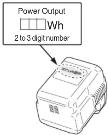
Notify the transporting company that a package contains a lithium-ion battery, inform the company of its power output and follow the instructions of the transportation company when arranging transport.
Lithium-ion batteries that exceed a power output of 100Wh are considered to be in the freight classifi cation of Dangerous Goods and will require special application procedures.
For transportation abroad, you must comply with international law and the rules and regulations of the destination country.
DESCRIPTION OF NUMBERED ITEMS (Fig. 2 - Fig. 46)
| ① | Rechargeable battery | 26 | Extend | 51 | Appropriate length 90 - 110 mm | 76 | Protrusion of carbon brush |
| ② | Latch | 27 | Holder case | 52 | Cover | 77 | Contact portion of brush tube |
| ③ | Battery cover | 28 | Lock | 53 | Case | 78 | Pull |
| ④ | Terminals | 29 | Projection of locking lever | 54 | Hook | 79 | Hanger |
| ⑤ | Ventilation holes | 30 | Hole | 55 | Press tabs (2 areas) | 80 | Bracket |
| ⑥ | Push | 31 | Cover | 56 | Reel | 81 | Quick-release belt |
| ⑦ | Insert | 32 | Knife | 57 | Groove | 82 | Hook |
| ⑧ | Pull out | 33 | D5 tapping screw | 58 | Fold back the middle part | 83 | Quick-release bracket |
| ⑨ | Pilot lamp | 34 | Cover bracket | 59 | Direction to wind nylon cord | 84 | Press |
| ⑩ | Line | 35 | M6x25 hex. socket button bolts | 60 | Secure in the stopper | 85 | Release mechanism |
| ⑪ | Power button | 36 | Cover holder | 61 | Stopper | 86 | Box spanner |
| ⑫ | Remaining battery indicator lamp | 37 | Flange ass'y | 62 | Eyelet line guide | 87 | Tighten |
| ⑬ | Main pipe | 38 | Wing | 63 | While holding the reel | 88 | Loosen |
| ⑭ | Housing side | 39 | Motor case | 64 | String the line through the eyelet line guide | 89 | Nut cover |
| ⑮ | Loop handle | 40 | Hex. bar wrench 4 mm | 65 | Locking holes of cover (2 holes) | 90 | Cutting blade |
| ⑯ | Handle fi xture | 41 | Threaded fastener of the motor case | 66 | Tabs of case (2 tabs) | 91 | Flange assy |
| ⑰ | M6x43 bolts | 42 | Hole | 67 | Power lamp | 92 | Motor case |
| ⑱ | M6 nuts | 43 | Nylon head | 68 | Handle | 93 | Cutting blade cover |
| ⑲ | Handle right | 44 | Screw (left rotation) | 69 | Lock lever | 94 | to detach |
| ⑳ | Lever | 45 | Nylon line | 70 | Lever | 95 | to attach |
| ㉑ | Handle left | 46 | Tap | 71 | Speed dial | 96 | Left side M10 installation nut |
| ㉒ | Handle fi xture | 47 | Button | 72 | Projection of locking lever | 97 | Projection of fl ange assy |
| ㉓ | M5 x 25 hex. Socket bolts | 48 | Tap/release | 73 | Wear limit | ||
| ㉔ | Locking lever | 49 | Wear limit mark (2 marks) | 74 | Brush cap | ||
| ㉕ | Release | 50 | Extends in 30 mm increments | 75 | Nail of carbon brush |
SPECIFICATIONS
POWER TOOL
| Model CG36DL CG36DL(L) CG36DAL CG36DAL(L) | ||||
| Pole type Straight type Extendable type | ||||
| Cutting capacity diameter 310 mm | ||||
| Rotation direction Counterclockwise as seen from above | ||||
| No-load speed 5800 - 7000 min | -1 | |||
| Operating time on one charge* (When supplied rechargeable battery is fully charged) | BSL3620 35 min (Normal) 15 min (High) BL36200 5.5 h (Normal) 2.5 h (High) | |||
| Battery BSL3620: Li-ion 36 V (2.0 Ah 10 cells) | ||||
| Weight (with nylon head, rechargeable battery, shoulder belt and cover) | 5.7 kg 5.5 kg | 6.0 kg 5.8 kg | ||
- The data in the above table is provided only as an example. Since type of grass, ambient temperature, rechargeable battery characteristics, work methods, etc. can vary widely the above should only be used as a rough guideline. Conditions: Outer diameter of nylon head 310 mm ,speed dial set to Normal or High. (lever left ON all the time)
CHARGER
| Model UC36YRSL | |
| Charging voltage | 4.4 V – 36 V |
| Weight 0.7 kg |
STANDARD ACCESSORIES
| CG36DL (LBR) | ① Battery (BSL3620)......................................1 |
| ② Charger (UC36YRSL)......................................1 | |
| ③ Nylon head......................................1 | |
| ④ Cover......................................1 | |
| ⑤ Hex. bar wrench 4 mm......................................1 | |
| ⑥ 17×19 Combi box wrench......................................1 | |
| ⑦ Protective glass......................................1 | |
| ⑧ Shoulder belt......................................1 | |
| ⑨ Hanger belt......................................1 | |
| ⑩ Battery cover......................................1 | |
| CG36DL (NN) | ① Nylon head......................................1 |
| ② Cover......................................1 | |
| ③ Hex. bar wrench 4 mm......................................1 | |
| ④ 17×19 Combi box wrench......................................1 | |
| ⑤ Protective glass......................................1 | |
| ⑥ Shoulder belt......................................1 | |
| ⑦ Hanger belt......................................1 |
| CG36DL(L) (LBR) | ① Battery (BSL3620)……1 |
| ② Charger (UC36YRSL)……1 | |
| ③ Nylon head……1 | |
| ④ Cover……1 | |
| ⑤ Hex. bar wrench 4 mm……1 | |
| ⑥ 17×19 Combi box wrench ……1 | |
| ⑦ Protective glass……1 | |
| ⑧ Shoulder belt……1 | |
| ⑨ Hanger belt……1 | |
| ⑩ Battery cover ……1 | |
| CG36DL(L) (NN) | ① Nylon head……1 |
| ② Cover……1 | |
| ③ Hex. bar wrench 4 mm……1 | |
| ④ 17×19 Combi box wrench ……1 | |
| ⑤ Protective glass……1 | |
| ⑥ Shoulder belt……1 | |
| ⑦ Hanger belt……1 | |
| CG36DAL CG36DAL(L) (LBR) | ① Battery (BSL3620)……1 |
| ② Charger (UC36YRSL)……1 | |
| ③ Nylon head……1 | |
| ④ Cover……1 | |
| ⑤ Hex. bar wrench 4 mm……1 | |
| ⑥ 17×19 Combi box wrench ……1 | |
| ⑦ Protective glass……11 | |
| ⑧ Shoulder belt……1 | |
| ⑨ Hanger belt……1 | |
| ⑩ Battery cover ……1 | |
| CG36DAL CG36DAL(L) (NN) | ① Nylon head…………………………1 |
| ② Cover…………………………1 | |
| ③ Hex. bar wrench 4 mm……………………1 | |
| ④ 17×19 Combi box wrench……………………1 | |
| ⑤ Protective glass…………………………1 | |
| ⑥ Shoulder belt…………………………1 | |
| ⑦ Hanger belt…………………………1 |
Standard accessories are subject to change without notice.
OPTIONAL ACCESSORIES (sold separately)
Battery
(BSL3620)
(BSL3626)
Back pack power supply
Cutting blade (CG36DL only)
(BL36200)

NOTE
For details of the operations, please see the BL36200 instruction manual.
When using the Cutting blade, have the Nut cover, Left side M10 installation nut and Counter weight set ready for installation.
Nut cover (CG36DL only)
Left side M10 installation nut (CG36DL only)
Counter weight set (CG36DL only)
NOTE
For details of the operations, please see the Counter weight set instruction manual.
Optional accessories are subject to change without notice.
APPLICATIONS
Trimming, scaling and mowing of weed.
BATTERY REMOVAL/INSTALLATION
1. Battery removal
Hold the housing tightly and push the battery latches to remove the battery (see Fig. 3).
CAUTION
Never short-circuit the battery.
2. Battery installation
Insert the battery while observing its polarities (see Fig. 3).
CHARGING
Before using the power tool, charge the battery as follows.
-
Connect the charger's power cord to a receptacle. When the power cord is connected, the charger's pilot lamp will blink in red. (At 1-second intervals)
-
Insert the battery into the charger.
-
Firmly insert the battery into the charger until the line is visible, as shown in Fig. 4 and 5.
3. Charging
When inserting a battery in the charger, charging will commence and the pilot lamp will light continuously in red.
When the battery becomes fully recharged, the pilot lamp will blink in red. (At 1-second intervals) (See Table 1)
(1) Pilot lamp indication
The indications of the pilot lamp will be as shown in Table 1, according to the condition of the charger or the rechargeable battery.
Table 1
| Indications of the pilot lamp | ||||
| The pilot lamp lights or blinks in red. | Before charging | Blinks | Lights for 0.5 seconds. Does not light for 0.5 seconds. (off for 0.5 seconds) | |
| While charging | Lights | Lights continuously | ||
| Charging complete | Blinks | Lights for 0.5 seconds. Does not light for 0.5 seconds. (off for 0.5 seconds) | ||
| Charging impossible | Flickers | Lights for 0.1 seconds. Does not light for 0.1 seconds. (off for 0.1 seconds) | Malfunction in the battery or the charger | |
| The pilot lamp lights in green. | Overheat standby | Lights | Lights continuously | Battery overheated. Unable to charge (Charging will commence when battery cools). |
(2) Regarding the temperatures of the rechargeable battery The temperatures for rechargeable batteries are as shown in Table 2, and batteries that have become hot should be cooled for a while before being recharged.
Table 2 Recharging ranges of batteries
| Rechargeable batteries | Temperatures at which the battery can be recharged |
| BSL3620 0°C – 50°C |
(3) Regarding recharging time
Depending on the combination of the charger and batteries, the charging time will become as shown in Table 3.
Table 3 Charging time (At 20^ C )
| Charger Battery | UC36YRSL |
| BSL3620 Approx. 60 min. |
NOTE
The charging time may vary according to temperature and power source voltage.
4. Disconnect the charger's power cord from the receptacle.
5. Hold the charger firmly and pull out the battery.
NOTE
After operation, pull out batteries from the charger first, and then keep the batteries properly.
How to make the batteries perform longer
(1) Recharge the batteries before they become completely exhausted.
When you feel that the power of the tool becomes weaker, stop using the tool and recharge its battery. If you continue to use the tool and exhaust the electric current, the battery may be damaged and its life will become shorter.
(2) Avoid recharging at high temperatures.
A rechargeable battery will be hot immediately after use. If such a battery is recharged immediately after use, its internal chemical substance will deteriorate, and the battery life will be shortened. Leave the battery and recharge it after it has cooled for a while.
CAUTION
If the battery is charged while it is heated because it has been left for a long time in a location subject to direct sunlight or because the battery has just been used, the pilot lamp of the charger lights up green. In such a case, first let the battery cool, then start charging.
- When the pilot lamp flickers in red (at 0.2-seconds intervals), check for and take out any foreign objects in the charger's battery connector. If there are no foreign objects, it is probable that the battery or charger is malfunctioning. Take it to your authorized Service Center.
Since the built-in micro computer takes about 3 seconds to confirm that the battery being charged with UC36YRSL is taken out, wait for a minimum of 3 seconds before reinserting it to continue charging. If the battery is reinserted within 3 seconds, the battery may not be properly charged.
ABOUT POWER LAMP
The power lamp indicates various statuses for the tool. (Fig. 6)
Table 4 shows the various statuses indicated by the power lamp.
Table 4
| State of lamp Status | Tool |
| Off | Power OFF |
| Red | Power ON |
| Blinking red | The lever is being pressed while the overload protection circuit of the tool is operating. |
| Quickly blinking red | The tool is operating abnormally. |
ABOUT REMAINING BATTERY INDICATOR
When pressing the remaining battery indicator switch, the remaining battery indicator lamp lights and the battery remaining power can be checked. (Fig. 6) When releasing your finger from the remaining battery indicator switch, the remaining battery indicator lamp goes off. The Table 5 shows the state of remaining battery indicator lamp and the battery remaining power.
Table 5
| State of lamp | Battery Remaining Power |
| The battery remaining power is enough. | |
| The battery remaining power is a half. | |
| The battery remaining power is nearly empty. Re-charge the battery soonest possible. |
As the remaining battery indicator shows somewhat differently depending on ambient temperature and battery characteristics, read it as a reference.
NOTE
Do not give a strong shock to the switch panel or break it. It may lead to a trouble.
To save the battery power consumption, the remaining battery indicator lamp lights while pressing the remaining battery indicator switch.
When using a back pack power supply (BL36200), please check the battery level on the battery level display of the back pack power battery.
For details, please see the BL36200 instruction manual.
PRIOR TO OPERATION
CAUTION
Pull out battery before doing any assembly.
1. Installing the loop handle (Fig. 7) (CG36DL (L), CG36DAL (L) only)
(1) Remove the M6 × 43 bolts (2 pcs.).
(2) Install the loop handle on the main pipe so that it leans against the housing.
(3) Place the handle fixture at the lower end of the main pipe and secure it firmly using M6 × 43 bolts (2 pcs.) and M6 nuts (2 pcs.).
NOTE
Secure the loop handle in a location that provides a good grip.
CAUTION
Install the loop handle properly and securely as instructed in the handling instructions.
If not attached properly or securely, it may come off and cause injury.
English
2. Installing the bicycle-style handlebars (Fig. 8)
(1) Using the 4mm hex wrench that is included, remove the four bolts that have been temporarily secured to the handle brace (A).
(2) Attach the right-hand side handgrip that has the lever and the left-hand side handgrip, and then carefully secure the handle brace (A) using the four bolts.
NOTE
Secure the left and right handgrips in a position that provides a good grip.
CAUTION
Install the left and right handgrips properly and securely as instructed in the handling instructions.
If not attached properly or securely, it may come off and cause injury.
3. Extending the main pipe (Fig. 9)
(1) Release the locking lever to allow the main pipe to be extended.
(2) Extend the main pipe as far as it will go, making sure that you hear it click.
NOTE
The motor will not operate unless the main pipe is fully extended.
When you push the power button, the red power light will flash rapidly.
(3) After extending the main pipe until it clicks, check that the hole of the holder case is aligned with the hole of the main pipe and lock the locking lever to fix the main pipe securely.
4. Installing cover (See Fig. 10 and 11)
WARNING
Be sure to install the cover in its designated location.
Failure to heed this warning may result in injury from flying stones.
NOTE
Use the supplied hex. bar wrench 4mm for installation.
(1) Use the supplied D5 tapping screw to install the knife in the cover. (Fig. 10)
(2) Align the two holes in the cover bracket and the cover and insert two M6 × 25 hex. socket button bolts. (The cover bracket is installed in the motor case.)
(3) Place the cover holder on the underside of the cover and use the supplied hex. bar wrench 4mm to alternately tighten the two M6 × 25 hex. socket button bolts until they are properly tightened.
CAUTION
Take care to avoid cutting yourself on the knife inside the cover.
Install the cover and knife properly and securely as instructed in the handling instructions.
If not attached properly or securely, they may come off and cause injury.
5. Installing the cutting blade (optional accessory) (CG36DL only)
WARNING
Before installing the cutting blade, be sure to attach the blade cover, wear thick gloves and take any other necessary precautions to protect yourself.
Before installing the cutting blade, check carefully and make sure that it is not cracked, deformed or in any other way damaged.
When installing the cutting blade, first attach the cutting blade cover, securing the hole in the middle of the cutting blade to the fl ange assy projection so that the cutting blade fi ts into the nut cover and the center part of the cutting blade does not slip. (See Fig. 21)
After installing the cutting blade, don't forget to remove the hex wrench and box spanner.
- If the left side M10 installation nut or the nut cover shows signs of wear or abrasion, replace with a new installation nut or nut cover.
(1) Insert the flange assy into the motor case. At this time, the wing of the fl ange assy should face the motor case side. (Fig. 18)
(2) To install the cutting blade, insert the supplied hex. bar wrench into the holes in the fl ange assay and the motor case, and, in order, attach the cutting blade and nut cover. (Fig. 19)
Install the cutting blade by rotating in the direction indicated by the arrow.
NOTE
After tightening securely, adjust so that the left side M10 installation nut can be fastened and loosened.
Failure to do so can cause deformation of the flange assay or baffle failure.
(3) Position the rounded side of the left side M10 installation nut so that it faces the box spanner side and then fasten securely. (Fig. 20)
(4) Check and make sure that the cutting blade has been properly installed. (Fig. 21)
6. Installing the shoulder belt
Use in combination with a BSL3620 battery.
WARNING
Be sure to attach the shoulder belt so that the grass trimmer can be carried correctly.
If you get the feeling the tool is not operating normally, turn off the motor immediately, remove the quick-release bracket of the shoulder belt and remove the tool.
CAUTION
If you do not support the tool when you pull the quick-release belt, it may fall causing injury or damage.
Hold the main pipe with one hand while you pull with the other hand.
Make sure the quick-release function operates normally before you start working.
(1) Place the shoulder belt on the shoulder as shown in Fig. 12 (For use outside of Europe, see Fig. 14) and engage it with the hanger on the tool. Adjust the shoulder belt to suitable length.
(2) To remove the tool from the shoulder belt, support the tool by holding the main pipe with one hand and use the other hand to pull the quick-release belt as shown in Fig. 12 (For use outside of Europe, see Fig. 14) to free it from the bracket.
(3) To strap on the tool, insert the bracket in the hook and insert the quick-release bracket over the hook and into the wide opening of the bracket. (Fig. 13) (For use outside of Europe, see Fig. 15)
Gently pull the shoulder belt to make sure that it is properly attached.
7. Installing the hanger belt
Use in combination with a BL36200 battery.
WARNING
- Be sure to attach the hanger belt so that the grass trimmer can be carried correctly.
If you get the feeling the tool is not operating normally, turn off the motor immediately, press the release mechanism of the hanger belt and remove the tool.
CAUTION
If you do not support the tool when you press the release mechanism, it may fall causing injury or damage.
Hold the main pipe with one hand while you push with the other hand.
Make sure the release function operates normally before you start working.
(1) Hook the hanger belt to the BL36200 harness (two places) as shown in Fig. 16. Then hook the belt to the hanger of the main pipe (one place). Adjust the hanger belt to a suitable length.
(2) To detach the tool from the hanger belt, hold the main pipe with one hand and press the release mechanism of the hanger belt from both sides as shown in Fig. 17.
To attach the tool, insert from below, making sure that is it properly attached
NYLON HEAD
Installation of semi-auto nylon head
1. Function
Automatically feeds more nylon cutting line when it is tapped.
Specifications
| Code No. | Type of attaching screw | Direction of rotation | Size of attaching screw |
| 335234 | Female screw | Counterclockwise | M10× P1.25-LH |
Applicable nylon cord
Cord diameter:
Fig. 22
Length: 4 m
CAUTION
The case must be securely attached to the cover.
Check the cover, case and other components for cracks or other damage.
Check the case and button for wear.
If the wear limit mark on the case is no longer visible or there is a hole in the bottom of the button, change the new parts immediately. (Fig. 25)
The nylon head must be securely mounted to the threaded fastener of the motor case.
For outstanding performance and reliability, always use Hitachi nylon cutting line. Never use wire or other materials that could become a dangerous projectile.
- If the nylon head does not feed cutting line properly, check that the nylon line and all components are properly installed. Contact your Hitachi dealer if you need assistance.
2. Installation (Fig. 18 and 23)
(1) Insert the flange assy into the motor case. At this time, the wing of the fl ange assy should face the motor case side. Next, align the holes of the fl ange assy and the motor case, insert the hex. bar wrench 4mm , and then turn to tighten the fl ange assy.
(2) Screw the nylon head directly to the threaded fastener of the motor case.
The mounting nut of nylon head is left-hand-threaded. Turn clockwise to loosen/ counterclockwise to tighten.
CAUTION
Install the nylon head properly and securely as instructed in the handling instructions.
If not attached properly or securely, it may come off and cause injury.
3. Adjustment of line length
Rotate and tap the nylon head on the ground. Nylon line is drawn out abt, 30mm by one tapping. (Fig. 24)
Also, you can extend nylon line with hands. This time the motor must be completely stopped.
Confirrm the line extends in 30~mm increments by tapping and releasing the bottom button while pulling the line ends of the nylon head. (Fig. 25)
Appropriate Length of Nylon Line
The appropriate length of the line when the tool is in use is 90 - 110mm . Extend the line to the appropriate length.
4. Nylon line replacement
(1) Prepare 4m of genuine nylon line in Fig. 22. (Code No. 335235)
(2) Press the opposing tabs, and then remove the cover from the case. (Fig. 26)
(3) Remove the reel from the case. (Fig. 27)
If there is nylon line remaining, hook the line in the groves, and then remove the reel.
If the nylon line does not extend when there is enough nylon line remaining, or when replacing the nylon line (Code No. 335235), wind the nylon line using the following procedure.
(4) Release about 150mm of the nylon cord from both ends, fold the middle part and attach to the hook on the spool. Next, wind the cord on the spool in the direction shown by the arrow, being careful not to crisscross it (Fig. 28, 29).
(5) Leave about 100mm - 150mm nylon cord unwound, hook and secure the line in the stopper. (Fig. 30)
NOTE
Do not cross the nylon line when securing the line in the stopper. (Fig. 31)
(6) Align the position of the stopper and eyelet line guide, and then insert the button through the case.
Release the line from the stopper while holding the reel lightly, and then string the line through the eyelet line guide. (Fig. 32)
(7) Press and snap the tabs of the case in the locking holes of the cover. (Fig. 33)
WARNING
Check to make sure the tabs are firmly snapped into the locking holes.
Operating the tool while the parts are not firmly snapped together may results in accidents or injury from flying part.
(8) Pull the line taught so there is no slack, and then cut the line to an extended length of 90mm - 110mm with scissors. (Fig. 34)
OPERATION
Trimming grass
WARNING
Do not operate the tool at night or under bad weather conditions when visibility is poor.
- Do not operate the tool when it is raining or right after it has been raining.
- Wear proper footwear to prevent slipping that could cause you to lose your balance and fall.
Do not use the tool on steep slopes.
When trimming grass on slopes that are not so steep, trim by moving towards the ridge.
Place the right hand on the handle and the left hand on the loop handle and hold it firmly.
Take care not to move the nylon head too close to your feet.
Do not raise the nylon head above your knee during cutting.
Do not use the tool where the nylon head may come into contact with stones, tree and other obstacles.
A nylon head can injure while it continues to spin after the motor is stopped. When the unit is turned off, make sure the nylon head has stopped before the unit is set down.
Do not use the tool within 15m of another person. When you work with someone else, maintain a distance of more than 15m .
- Blade thrust may occur when the spinning blade contacts a solid object in the critical area.
A dangerous reaction may occur causing the entire unit and operator to be thrust violently. This reaction is called blade thrust. As a result, the operator may lose control of the unit which may cause serious or fatal injury. Blade thrust is more likely to occur in areas where it is difficult to see the material to be cut.
- Insert the battery while observing its polarities.
2. Turn on the tool. (Fig. 35)
Press the power button on the housing, the power goes on and the power lamp on the handle lights red.
Pressing the power button a second time turns the power off and the red lamp on the handle goes off.
[Auto power off]
When the power is turned on but the lever is not used for one minute, the tool is automatically turned off. To turn the tool on again, press the power button a second time.
WARNING
Never leave the tool with the power on. This could result in an accident.
3. Lever operation and brake (Fig. 36)
To start rotation of the cutting blade, with the power turned on, pull the lever while pressing the locking lever.
When you release the lever, the brake engages in 1 - 3 seconds, stopping rotation of the cutting blade.
Make sure that the brake operates normally before using the tool.
4. Speed dial (Fig. 37)
A speed dial for changing the rotational speed in the range of 5800 - 7000min^-1 is provided on the housing. Turn the dial clockwise to increase the speed and counterclockwise to reduce the speed.
5. Trimming grass
Grip the handle from above, press the locking lever and pull the lever to start cutting head rotation. (Fig. 38)
Release the lever when you finish trimming and stop the motor.
- Place your thumb on the handle and grip the handle with your other fingers. (Fig. 39) (CG36DL, CG36DAL only)
Place your thumb on the loop handle and grip the handle with your other fingers. (Fig. 40) (CG36DL (L), CG36DAL (L) only)
Take a posture that makes it easy to move.
[Grass trimming techniques]
Do not swing the pipe, but use the hips to move the nylon head horizontally from right to left in an arc while going forward and use the left side of the nylon head for cutting grass. (Fig. 41)
OPERATIONAL CAUTIONS
Continuous work
This tool comes with an over-heat protection circuit that protects the electronic parts that control the rechargeable battery. In continuous trimming work, tool temperature will rise and eventually trigger the over-heat protection circuit, which will shut down the tool.
If this happens, let the tool cool for a length of time. When the temperature drops, it will again become possible to use the tool. When the rechargeable battery has to be exchanged during continuous operation, let the tool rest for about 15 minutes.
Overload Protection
This tool comes with an overload protection circuit to protect the electronic parts controlling the tool. In continuous overload during trimming work (locking the nylon head, etc.), the overload protection circuit shuts down the motor. If this happens, turn OFF the power, and then resolve the problem causing the overload.
The power lamp blinks if the lever is pressed after the motor has stopped (see page 13, "ABOUT POWER LAMP"). The power automatically turns OFF if the power lamp blinks longer than 5 seconds. If this happens, resolve the problem causing the overload, and then switch the power button ON to resume using the tool.
Carrying the tool (Fig. 42)
CAUTION
- Remove the storage battery and use the cutting blade cover to protect the cutting blade when carrying the tool. Carrying the tool without first putting the cutting blade cover in place exposes the human body to the blade, which can result in injury.
○ Carry the tool holding with hands and keeping the cutting blade away from the body. - When retracting the main pipe, be careful of the pointed end and take care not get your fingers caught. (CG36DAL, CG36DAL (L) only)
Release the locking lever and retract the main pipe. Lock the locking lever until the projection hits the main pipe. This procedure allows you to reduce the tool to a compact size.
The main pipe can be retracted to any position. Choose a suitable length for carrying and storage. (CG36DAL, CG36DAL (L) only)
MAINTENANCE AND INSPECTION
CAUTION
Pull out battery before doing any inspection or maintenance.
1. Checking the condition of the nylon head
The nylon head should be checked regularly. If worn or broken nylon head can slip or decrease the efficiency of the motor and burn it out.
Replace worn nylon head with new ones.
CAUTION
If you use a nylon head of which point is worn or broken, it will be dangerous. So replace it with a new one.
2. Check the Screws
Loose screws are dangerous. Regularly inspect them and make sure they are tight.
CAUTION
Using this power tool with loosened screws is extremely dangerous.
3. Inspecting the carbon brushes (Fig. 43)
The motor employs carbon brushes which are consumable parts. Since and excessively worn carbon brush can result in motor trouble, replace the carbon brush with new ones when it becomes worn to or near the "wear limit". In addition, always keep carbon brushes clean and ensure that they slide freely within the brush holders.
NOTE
When replacing the carbon brush with a new one, be sure to use the Hitachi Carbon Brush Code No. 999015.
4. Replacing carbon brushes
Take out the carbon brush by first removing the brush cap and then hooking the protrusion of the carbon brush with a slotted head screw driver, etc., as shown in Fig. 44.
When installing the carbon brush, choose the direction so that the nail of the carbon brush (see Fig. 45) agrees with the contact portion of brush tube. Then push it in with a finger as illustrated in Fig. 46. Lastly, install the brush cap.
CAUTION
Be absolutely sure to insert the nail of the carbon brush into the contact portion of brush tube. (You can insert whichever one of the two nails provided.)
Caution must be exercised since any error in this operation can result in the deformed nail of the carbon brush and may cause motor trouble at an early stage.
5. Cleaning of the outside
When the grass trimmer is stained, wipe with a soft dry cloth or a cloth moistened with soapy water. Do not use chloric solvents, gasoline or paint thinner, as they melt plastics.
6. Storage
Store grass trimmer in a place in which the temperature is less than 40^ and out of reach of children.
NOTE
Storing Lithium-ion Batteries
Make sure the lithium-ion batteries have been fully charged before storing them.
Prolonged storage (3 months or more) of batteries with a low charge may result in performance deterioration, signifi cantly reducing battery usage time or rendering the batteries incapable of holding a charge.
However, significantly reduced battery usage time may be recovered by repeatedly charging and using the batteries two to five times.
If the battery usage time is extremely short despite repeated charging and use, consider the batteries dead and purchase new batteries.
CAUTION
In the operation and maintenance of power tools, the safety regulations and standards prescribed in each country must be observed.
SELECTING ACCESSORIES
The accessories of this machine are listed on page 362.
Important notice on the batteries for the Hitachi cordless power tools
Please always use one of our designated genuine batteries. We cannot guarantee the safety and performance of our cordless power tool when used with batteries other than these designated by us, or when the battery is disassembled and modified (such as disassembly and replacement of cells or other internal parts).
TROUBLESHOOTING
Use the inspections in the table below if the tool does not operate normally. If this does not remedy the problem, consult your dealer or the Hitachi Authorized Service Center.
| Symptom Possible cause Remedy | ||||
| Charger The Charge lamp does not go on. | The power plug is not connected to an AC outlet. | Connect the power plug to an AC outlet. | ||
| The battery is not properly connected to the charger. | Insert the battery so that it is properly seated in the charger. | |||
| The battery or charger electrodes are soiled. | Use a cotton swab or other tool to clean the electrodes. | |||
| The battery is extremely hot. Allow the battery to properly cool before charging. | ||||
| Tool Does not operate. The rechargeable battery is depleted. Charge the rechargeable battery. | ||||
| The rechargeable battery has not been properly installed. | Remove the rechargeable battery from the battery compartment in the tool and check for and remove any foreign matter. Also check the battery electrodes for soiling, water or other foreign matter. Use a cotton swab for cleaning. Make sure that the rechargeable battery is pressed in until it clicks into place. | |||
| The power has not been turned on. Press the power button on the housing to start the tool. This tool comes with an auto power off function. The power is automatically turned off if nobody pulls the lever during a one minute period after power on. To turn the tool on again, press the power button a second time. Pressing the power button a second time turns the power off. | ||||
| The main pipe is not fully extended (The red light blinks rapidly) (CG36DAL, CG36DAL (L) only) | To prevent accidents due to malfunction, the tool is designed so that the motor will not operate unless the main pipe is fully extended. Extend the main pipe fully until it clicks. | |||
| The lock lever was not pressed when the lever was pulled back. | To prevent accidents from incorrect operation, the lock lever must be pressed while the lever is pulled back to start the motor. Hold the handle from above and press the lock lever while pulling the handle. | |||
| The tool pulls in large volumes of grass that are caught between the cover and the nylon head, the tool is overloaded. | This is the effect of a function that protects the rechargeable battery by turning off the motor when the tool is exposed to an excessive load. Turn off the tool and remove the cause of the overload. Press the power button once again to continue operation. | |||
| Symptom Possible cause Remedy | ||||
| Tool Goes on, but soon stops. | ||||
GUARANTEE
We guarantee Hitachi Power Tools in accordance with statutory/country specific regulation. This guarantee does not cover defects or damage due to misuse, abuse, or normal wear and tear. In case of complaint, please send the Power Tool, undismantled, with the GUARANTEE CERTIFICATE found at the end of this Handling instruction, to a Hitachi Authorized Service Center.
NOTE
Due to HITACHI's continuing program of research and development, the specific cations herein are subject to change without prior notice.
Information concerning airborne noise and vibration
The measured values were determined according to EN50636-2-91 and declared in accordance with ISO 4871.
Measured A-weighted sound power level: 85 dB (A).
Measured A-weighted sound pressure level: 76 dB'A).
Uncertainty K: 3 dB (A).
Wear hearing protection.
Vibration total values (triax vector sum) determined according to EN50636-2-91.
Vibration emission value a_h,w = 4m / s^2
Uncertainty K = 1.5m / g
The declared vibration total value has been measured in accordance with a standard test method and may be used for comparing one tool with another.
It may also be used in a preliminary assessment of exposure.
WARNING
The vibration emission during actual use of the power tool can differ from the declared total value depending on the ways in which the tool is used.
- Identify safety measures to protect the operator that are based on an estimation of exposure in the actual conditions of use (taking account of all parts of the operating cycle such as the times when the tool is switched off and when it is running idle in addition to the trigger time).
SYMBOL
WARNING
Cordon de nylon applicable
VEILIGHEIDSWAARSCHUWINGEN
VOOR ELEKTRISCH GEREEDSCHAP
WAARSCHUWING
VOORZORGSGMAATREGELEN VOOR ACCU EN LADER
Si no se conecta adecuadamente y de forma segura, seSEOSEOSEOSEOSEOSEOSEOSEOSEOSEOSEOSEOSEOSEOSEOSEOSEOSEOSEOSEOSEOSEOSEOSEOSEOSEOSEOSEOSEOSEOSEOSEOSEOSEOSEOSEOSEOSEOSEOSEOSEOSEOSEOSEOSEOSEOSEOSEOSEOSEOSEOSEOSEOSEOSEOSEOSEOSEOSEOSEOSEOSEOSEOSEOSEOSEOSEOSEOSEOSEOSEOSEOSEOSEOSEOSEOSEOSEOSEOSEOSEOSEOSEOSEOSEOSEOSEOSEOSEOSEOSEOSEOSEOSEOSEOSEOSEOSEOSEOSEO SEO
HVAD ER HVAD? (Fig. 1)
- Inspiser nylonodet for du begyinner a arbeide.
Ikke bruk verktoyet hvis nylonhodet er sprukket, skadet ell er boyd.
VEDLIKEHOLD OG INSPEKSJON
FORSIKTIG
TENIKEΣ ΠPOEIΔΟΙΟΗΣΕΙΣ
AΣΦΑΛEIAΣ HΛEKTPIΚΟΥ EPΓΑΛΕΙΟΥ
IPOEIAOIOIHEN
4 Vymena nylonov struny
2. Introduceti accumulatorul in incarcator
| Incărcător Accumulator | UC36YRSL |
| BSL3620 Approx. 60 min. |
NOTA
Cepel (Iba modely CG36DL)
(BL36200)

POZNÁMKA
OBsI MEPH3A B63OJACHOCT IPN PABOTAC EJEKTPUQECHN HHCTPYMEHTN
NPEAUYPENKDEHNE
PpoyeTe BCnHN HnCTpyHcHn N npEynpeKHeHna 3a 6e3onacHOCT.
HecnasaBHeTo Ha nHCTpyKunTe n npdeynpeKeJdEHNrTa MoKe Da DoBeDe Do eJeKTpnueckn ydap, noKap N/nn cepno3Hn HapaHbAHn.
3ana3ete n cbxpaHraBaIte HnCTpyHcHnTe nocleDbau cnpaBn npnoJeHne.
TePMnHbT "eIeKtpnueckn HNcTpymeHT B npdynpexKeHHra Tce OTHaCdo Baunr eIeKtpnueckn (Ka6eJeH) nn anymylaTopeh (Be3KnuE) nHCTpyMeHT.
1) Be3onachocHT Ha pa6oTHOTMRCTO
a) PoiBpHaIe pa6OHTo MRCTo NOpeHcN Do6pe OCBTeHo. Pa3xBpIaN Hn Cna6o OCBTeHN pa6OTHN MeCTa Ca IpeDIOCTaBAk 3a INuDEHTN.
b) He n3noI3BaIte eIeKtpnueChn HNCTpyMeHT BBB B3pHBOONacHa CpeDa, npn HaJIuYe Ha 3aIaIMN TeUHOCTn, ra3 nn Ipax. EJeKtpnuecknte INCHTpymeHTn IPOIN3BeJdAt NcRpn, KOHTo MORaT da DOBeaT da Bb3IINaMeHRAHe.
c) He no3BolBaIte DoCTbI Ha CtpaHnHn Iuca N Deua npa p6oTa c eIeHTpueChn HNcTpymEnTu. HeBHmAHne IO BpeMe Ha pa6oTa MoKe Ja DOBeDe Do 3aY6a Ha KOHTPOBbpxy IpOceca.
2) EJektpnuecka 6e30nachOCT
a) ⅦeNcEJIte Ha eIeHTpUeCHTe HhCTpyMeHTn TpRABa Da OTROBAPr HA KOHTaKTHe. HmKora He npabTe KaBHTo N da6bNo IpomEHn No ⅦeNcEJIte. He n3noJ3BaIte npexoHN ⅦeNcEJIH CbC 3a3eMeHN eIeHTpUeCKn HhCTpyMeHTn. ⅦeNcEJI, KOHTo He ca MoDnΦuIpaHN cBoTBETCTBaT Ha KOHTaKTHe HamaJIbaT pNcKa OTe IeIeKTpUeCKn yJaP.
b) H36raBaiTe HOHTaKT C TaJIoTO npn pa6ota c eIeHTpueechn HNCTpyMeHTn NO 3a3eMeHN NOBbpxHOCTn, HATO Tpb6n, paHaTOpH IN XlaAunHnU.
CbuecTByBa NOBnWeH pIck OT eNKeTpneChn yIap, aKO TJIATO Bu cTaHe qAcT OT 3a3eMHTenHHa KOHTyp.
c) He n3laarte eIeHTpuechHTE HNCTpyMeHTn Ha IbHKn Blarra.
IonaandaHTo Ha Bnara B eJekTpuecknte HnCTpyMeHTn NOBnShaBa pNcKa OT eJekTpueckn ydap.
d) He hapywaabaTe ueocCTTa Ha Ka6eHnTe. Hnkora He Hocete N He dbpnaite eIeHTpueechn HnCtpymeHT 3a Ka6eHa; npn n3KIOUbaHe ot KOHTaTbPnaTe 5eenceJa, He Ka6eHa.
Na3ete Ka6eJnte OT n3ToUHnHa Ha TOnnHa, OT cMa3OChn MaTePnaJn, OcTpN p6ObE N NOBHHN KOMNOHEHTN.
HapaHeHn nn npenIteHn Ka6eHn nobuaBaT pncKa OT eJeKtpueeckn ydap.
e) Horato pa6oHTe c eIeKtpnueechn HnHCTpymeHT Ha oTKpHTO, n3noJ3BaHTe ydJIHNTeJ, NOxOJa, 3a pa6oTa Ha oTKpHTO.
H3noJ3BaIte Ka6eI , NOxOJa 3a BbHsHn yCIOBn, KOITo HAMaJIBa pIcKa OT eJIeKTpueckn yIap.
f) Aho e HaIOXHTeJIHO 3nOJI3BaHeTo Ha eIeHTpUeCKH HcTpymEHT BbB BnaHH yCIOBn, n3nOJI3BaHTeypeN C dInepeHuaHa 3aunTa (RCD) cpeuyteuKa.
13noI3BaHeTo Ha yCTpoIcTBO 3a DnΦepeHuaHa 3aunTa (RCD) HamaJIyBa pncKa OT eJeKTpueckn yap.
3)Лична6e3oNaCHOCT
a)БbTe 6dTeHNH, BHMMaBaIte B DeICTBnraT a cn n3noJ3BaIte pa3yMHO eJeHTpueeCKnTe HhCTpyMeHTn.
He n3no3BaIte eIeHTpueeCKn HNCTpyMeHT, HORATO CTE n3MOpEHN, INN NOD BINRAHNETo Ha JeKapCTBeHN cpeCDTa, anHOxOJ INN ONHaTH.
BcraKo HebHMaHHe npu pa6To c eNeKtpnueckn HNCTpyMeHTN MOHe da DOBeDe Do cepNo3HN HapaHbAHn. 2
b) H3noJ3BaIte IHHn npedna3Hn cpeCTBa. BHHaHnocTe 3auHTN OuHa nMaca.
3aunTHnTe cpeCTBa, KaTO npOTNBONpaxOba MACKa, 3aunTHn ObyBKN C yCTOuYBa Ha NtB3raHe NOmETKa, KACKa HnAHTNFOHn, CNOpe YCNOBnTa Ha paBoTa, HamaJIbBAT ONaCHOCTTA OT HapaHBAHe.
c) PpeoTbpaTaBaHe Ha CnyaHNO BHIIOUbaHe. YBepete ce, ye 6yToHbT 3a CTapr Ha ypeDa e B n3KIOUeHO NIOJOKeHne, npEn Da CBbpKeTe eJeKTPnueChn HNCTpyMeHT KbM N3TOuHN Ka3xpaHbAne H/nn 6atepna, KaHTo N npEn da ro B3emTe nn ppeHacrte.
IpehaHTo Ha HCTpyMeHTn C npbCT Ha CTapT 6yToHa, HnHa npeBKnUOyBaTeNa Ha 3axpaHbaHeTo, Hocn OnaCHOCT OT HNcNDeHTN.
d) OtcpaheTe BCnHn raeuHn n dpyrN KIOObe, npedn da BKnIOHTe ypea.
Faeuen KJIou HIN INHCTpymeHT, 3a6paBEN B PotaunOHn KOMNOHeHTn Ha eJeKTPnueckn INHCTpymeHT, MoHe da DoBeDe do HapaHraBaHe.
e) He ce npecraaTe. Ppe3 qnoTo Bpeme Tp6Ba Da mate Cta6nHa onopa n da noDbPkaTe BaIaHC Ha TJIOTO.
Toba OCHyprBa NO-IO6bP KOHTpOIN Bbpxy eNEKtpnuecknte INHCTpyMeHTN Pn IN3BbHpeDn CInTuayu.
f) Hocete npoxoio o6leKno. He hocete npekaIeHO shpOKn dpexn nn 6NHyTa. Na3eTe Hocata, dpexnte n pbKaBnCtne cn OT noDbHnn KOMTOHEHTN.
Unpoknte dpexn, bnyta n Dbna Kocmaorat da 6bdat 3axbaHATN OT NOBvHHNTe KOMTOHEHTN.
g) Ako ca ocHrypeHn ycTpoHcTBa 3a cBbP3BaHe c npaxoyIOBHTeHH HhCTaIauHN, yBepTe ce, Ye Te ca Cbbp3aHn n Ce n3NoJ3Bat npabUInHO.
H3noJ3BaHeTo Ha npaxoyIOBNTeN u cHJHOH MOHe Da HamaJIb Cbbp3aHHTe Cbc 3aMbpcBAHeTO pICHOBe.
4) Ehcnoataa n nodpbHHa Ha eJeHTpueechn HhctpyMeHTn
a) He hacnBaIte eIeHTpueeCKHTE HcHTpyMeHTN. N3noJ3BaIte NOxOJaE eJIeHTpueeCHN HHCTpyMeHT 3a CbOTBeTHNTe cJIH.
Iopxodnay eNektpueckn HNCTpymeHT OCHyprBa no-dobpa n no-cnrypha pa6ota npn PpeBnDeHnte HOMHaHn npaMeTp.
b) He n3no3BaIte eIeKtpnuecknT HNCTpyMeHT, aHO He MoKe Da 6bDe BKNIOUeH NIN N3KNIOUeH OT cbOTBETHNcTApT 6yTOH NIN PpeBKnIOUBATeJ.
BceH eJektpueckn HcTpyMeHT, KOHTo He MoKe Da ce KOHTpOJIpa O T CnycbKa, e ONaCeH N NOJIeKHa peMOHT.
c) N3HIOUeTe 电CEnca Ha HnCTpyMeHTa OT N3TOOHNa Ha 3axpaHbAne n/nn O6aTePnTa, npedn da N3BbPwBaTe HAcTpoiKn, npn CmHa Ha npncTabHN nn npn cbxpaHeHne.
Te3n npedna3Hm MepKn HamaJraBt pNcKa OT CnyaHNO HeKeHaHO BKNIOUbaHe Ha eNEKtpnueckn INHCTpyMeHT.
d) CbxpahraBaHTe HEn3noJ3BaHHTe eIeHTpuYeCKn HHCTpymeHTn DaJeY OT DOCTbn Ha Deua N He No3BOJRAHTe Ha IInca, He3aNo3HaTHn C HaunHa Ha pa6Ota C IHCTpyMeHTnte, n C Te3N HHCTpyKcUn, da pa6OTr CTAX.
EneKtpueechnte HnCTpyMeHTn npedctabIraBt onaCHOCT BpbTeHa HeONITHn Iuca.
e) NpOdbpKaHte eJektpnuechnte HNcTpymeHTn. PpOBepaBaiTe cHtPOBkata n 3aKpeNBaHeTo Ha NpOdBnHHte qactn, npOBepaBaTe 3a NobpeDeHN qactn n dpyr n cbctoHHn, KOnTO MORAT da ce oTpa3rHa pa6otata Ha eJektpnuechnte HNcTpymeHTn.
Ako yctaHOBHTe NOBpeHn,OTCTpaHete rH npEdu Da H3noL3BaTe eLEKTPnueCHNTe HHCTpyMeHTN.
MHoro 3IIOJOLyKHe Ce IbJIHaT Ha IOna IODpBHKHa HaeNekTpncckte NHCtpymentn.
f) PoiDbPkaIe peKeIuTe HNCTpyMeHTn HatoyeH N uCtN.
PpaBnHNO nOaIbPkaHnTe peKeu nHCTpyMeHTn, C HatoeHN peKeu enEmeHTn, Ce ynpablaBaT N KOHTPOINpAT NO-JleCHO.
g) H3noI3BaIte eIeHTpueeCKn HNCTpyMeHTn, npHcTAbHN n AHCecOaPn, n T.H., CbIraCHO Te3n HNCTpyKUHN, KATO B3EmTe NpeBnD pa60THnte ycNoBnN n BnDa pa60TH, KOITo ige ce H3BbpWBat.
H3noI3BaHeTo Ha eJekTpueeCKn HNCTpyMeHTn He NO npEaHa3NaYeHne MOHe da DOBeDe Do NOBuWeH pNCK N ONaCHN CNTyaUHN.
5) EKcNlloataunn H noDpBkHa Ha eJeHTpnueckn HHCTpyMeHTn 3axpaHbHN OT 6aTePN
a) 3apeHdaTe ypeDnte cMo cbc 3apAHDHTe yctpoiCTBa, nocouehn OT npOn3BOIDNTeI.
3apAnHO yCTPOINCTBO, NOxOJaIO 3a eINH TnIbATEPN, MoKe Da Cb3daJe pNCH OT NOnHAp PnNn3No3BaHe c Dpyr TnIb BATEPN.
b) H3noJ3BaIte eJIeKTPnueCKeHTE NHCtpymeHTN camO c nocouehna 3a TxA TIN 6aTePHN.
H3noJ3BaHeTo Ha npyr TnB 6aTeepu Cb3daBa pNCK OT HapaHBAhe N noKap.
c) Horato 6aTeepHnTe He ce n3noJ3BaT, Te He TpA6Ba Da Ce CbXpaHnBat B 6n3oCT Do dpyrM MeTaJIHH npeDMeTH Hato HJaMePn MOHeTn, KIOOyOBe, NPOHn, BHTObE nn dpyrMaJIHN MeTAJIHH npeDMeTH, HOHTO MORaT da OcbIeCTBt KOHTaHT MeKdy KJIeMNTe HM.
HOHTAKT MeKdy KJIeMnTe Ha 6aTePnHte MoKe da DOBeDe OT NCKPN NnN NoHaP.
d) Ipn HeNoDxOJaUyCNoBnHa CbXpaHeHne, 6aTeepnte Morat Da N3TeKaT; N36raRbaIte HOHTaHT. AHO ClyuayHo BJe3eTe B HOHTaTc C eJeKTPoNtHaTa TeYHOCT, N3IIaKHeTe O6NJHO C BODa. AHO nonaJHe eJeKTPoNt B OUYTe, N3IIaKHeTe O6NJHO nOTbpcTe MeiunHcA NOMOUI.
EeKToPnTbT Ha 6aTepeHnTe MoKe da npuHHn Bb3naHeHne HnNn3raepHHn.
6) 06cIyHbAHe
a) 06cIyHbAHeTo Ha eIeHTpNueChnTe HhCTpyMeHTn TpaBb Da ce N3BbPbBa cAmO OT KBaJIHΦHnIpaHn CepBn3Hn pa6oTHnI, npH n3NoJ3BaHe HaOpHnHaJIHn pe3epBHN qAcTn.
ToBa ige rapaHTnpa 6e3oNaChocTt npn pa60Ta c eIeKtpuuecknte HNcTpymEnTu.
BHIMAHNE
He donychaite B 30Hata Ha pa6ota deua n Bb3paCTHn xopa.
Horato He H3noI3BaTe eIeHTpuYeCHnte HHcTpymENTn, cbxpaHbBAute rHa daJeu OT DOCTbN Ha Deua N Bb3pactTHXopa.
ПЕРОРьн 3A БE3ONACHOCT ПИ ПАБOTA C TРИМЕР 3A TPEBA
BAHHO
IPOYETETEBHIMATEJIHO IPEENYIOTPEBA3ANA3ETE 3A BbDEU CNPABKNI
Noctabete HNCTpyMeHTa Bbpxy paBHa NOBbpxHOCT.
He pa6oTeTe c HnCTpyMeHTa Ha pa3cToHHe Do 15 M oT Xopa N KINBOTHN.
YBepeTe ce,Ye HauIIOHOBaTa InaBa He ce DoInpa Do 3eMaTAtbPBeTaHnIpaCTeHnI.
БezOTROBOPHOTo CTAPHTIPAHe MoKe Da DoBeDe Do HapaHRABaHe.
8.He nKcpaIte IocTa 3a 3acToOpraBaHe.
CnyaHTo H3dbpNaHe Ha3ad Ha loCTa MoKe da DOBeDe Do HeOyakBaHO HapaHraBaHe.
He doKocBaTe CTpyKHN, noJenHaJIIN NO IHCTpyMeHTA. OTCpaHETe HcYetKa.
Hecnata3BaHeTo Ha TOBa MoKe Da DoBeDe Do HapaHaBaHe.
Ako n3no3BaTe neiCMeHbP HnI pyro MeuHcHo eEeKtpoHHO yCTpoHCTBO, He paBOTe C n He do6nKaBHe INCTpyMeHTa.
Pa6oTaHa eJIeKTPpoHHOTyCtpoNCTBO MoHe da 6bJe IOBJIINrHa.
He n3noI3BaIte HnCTpyMeHTa B 6JIH3OCT Do Ipeu3HN yCTpOJCTBA KaTO KJIeTbUHN TeJefoHN, MaHHTHN KapTN nn EJIeKTHPOHH MeDNIH NyCTpOJCTBa 3a CbXpaHEHne Ha daHHN.
Ako Hapabnto Ta, MoKe Da ce CTnHr Do He npBnHa pa6Ota, Nobpea nn 3aYbHa daHHN.
BHIMAHNE
- He BkIIOuBaIe HauIOHOBaTa rnaBa 3a p3aHe Ha dpyro,OCBeH TpeBa.He n3NoI3BaIte HnCTpyMeHTa B IOKBn I ce yBepTe,Ye NoUbaTae He BIn3a B DoCer C HauIOHOBaTa rnaBa.
-
HhctpymehTcBbPka npeun3Hn yactn He 6nBa da 6bJe n3nyckan nn noDnaRn Ha cnIeH yap nn BOda. HhctpymehTMOKe da ce nobpei nn da He pa60tn npabuHIO.
-
Korato INHCTpyMeHTbT Ⅲe ce cbxpaHraBa cIeD n3noJI3BaHe IIN Ⅲe ce TpaHCnOpTnpa, IpemaxHeTe HauJIOHOBAtA rJaBa.
4.He TpeTnpaTe HnCTpyMeHTa C nHcKtNcUdIn Nn DpyrXmMknA. TaHnBa XmMknAIn MoKe Da npuHrt NyHaTHnN n DpyrNOBpeH. - CmeheTe npdeynpeDHTe eTNKeTn c HOBN, KOraTo Te CTaHaT TpydH 3a pa3no3HaBaHe NIn HeueTINBn IN KOraTO 3anOHT da ce 6eJIrT.
PonckaTe npedynpeDnteHn eTNKeTOn OT dNlbpa cn.
6.He DoKocBaIte DnIraTeIeH HenOceDCTBeHO CneIynoTpe6a,3aIoTO MOKe Da e MHoro ropeu.
ПЕДПАЗНМЕPHN3A 3APЯДHOTO YCTPOICTBO
- Binhari 3apeKdaIte 6atepnaT npn TempepaTpa ot 0^ - 40^ . TempepaTpa noD 0^ ue npuHH npesapeKdaHe, KOeTO e onaCHO. BatepTa He MoKe da 6bJe 3apeKdaHa npn TempepaTpH nAd 40^ Hai-noxOJaTa TEMpepaTpa 3a 3apeKdaHe e 20^ - 25^
- Korato eHNO 3apeKdaHe npHKIOUH, ocTaBeTe 3aprHOTO yCTPOIcTB0 3a OKoJIO 15 MNHyTN ppeIN cJeBaIoTO 3apeKdaHe Ha 6aTePn. He 3apeKdaIte NOBue O T DBe 6aTePn nocLeDoBaTeJIHo.
3.HeDonyckaTeHaBIn3aHeTo HaUyKnTeNa BOTbopa 3a Cbbp3BaHe Ha aKymJaTopH6aTeepn. - He noctabrayte npedmetn Bbpxy OTbopnte 3a oxlaqdahe Ha 3aprdHOTO yCTPOIcTBO.BkapBaHeTo Ha MeTaJIHN HJN 3anaJIIMN IpemETn BBB EHTINaLIOHHNTe CLOTOb e IOBeDe DO ONaCHOCT OT eJEKeTHpUeCKn YdAp JNJ NJIe NOBpeRt 3aprHOTo yCTPOIcTBO.
5.ИЗнOL3BaHToHaИЗTOUeHa6aTePnI ΜE NOBpeN 3aprHOTO yCTpOInCTBO. - BbPheTe 6aTePnraTa B Mara3Ha, OT KoITo e 3aKynHe, BeHara CneI KaTO uKbJa Ha KINBOT Ha 6aTePnraTa cTaHe npeKaJIeHO KbC, 3a Da ce N3NoJ3Ba. He H3XBpJIrTe N3TOUeHN 6aTePnN.
- HnKora He pa3rno6BaIte akymyIaTOPHITe 6aTePN nn 3apAnHOTo yCTpOInCTBO.
- HnKora He daBaIte Ha Kbco aKymyIaTOPHHe 6aTePnH. Kbco cBeINHeHne MoKe Da npuHHrToJAM eJeKtpnueckn Tok n npperpaHahe. Toba moKe da DOBeE do NOBpeHa Ha 6aTePnra.
9.He n3xBpIyTe 6aTePnB OrBn. Ako 6aTePnTa n3ropn, Tm MoHe da ekcnloDnpa.
ГРИХА 3A ЛNTHEBO-иOHHATA BATEPЯ
3a da ydbnHHTe HNBOTa Ha JNTHeBO-NOHHata 6aTePnra, TnIMa 3aunTHa FyHKpna 3a npekbcBaHe Ha NODabaHTo Ha3apn.
B clyuante 1 do 3, onncan no-dony, korato n3no3BaTe TOBA u3dene, dopn npn HATNCKaHe Ha cnycbKa, MOTOpbT MOKe da cnpe. TOBa He E B CLeDCTBne Ha NOBpeDa, a Ha 3aunTHa fYHKqyra.
- Korato pa3pndbT ha 6aTeepnra HamaJe e 3NaHTeJHo, MOTOpbT cnpa.
B TaKbB CnyaH, 3apeTe 6aTeepnra He3a6abHO.
-
Ako INHCTpymEnTbTe 6nI npTeOBapeH, MOTOpbT MOHe Da cnpe. B To3n CnyaH, OCBO6ODeTe cnycbKa N OTCTpaHete npuHHaTa 3a npetOBapBaHe. CJeD TOBa MOHe Da n3NoJ3BaTe ypeDa OTHOBO.
-
Ako 6atepna Ta e nperepa I npn npetobapbahe, TMOKe da OTHaKe Da pa6oTn.
BTo3nCnya, CnpTe n3noJ3BaHeTo N, N octaBeTa da ce oxlaDi. CJIeT TOBa MoKe Da n3noJ3BaTe ypeDa OTHOBO.
OcBeHToBa,MOJI,CnA3BaIte CLeHNITe npeDynpexDeHna. IPEyNPEKDEHNE
3aДа npedOTbpaTHTe pa3peKdAhe Ha 6atepnaTAt, 3aRpaBaHe, NOBa Ha dIM, 3anaIbAbe n ekCnIO3n, yBepete ce, ye cna3BaTe yKa3aHnTa 3a 6e3OnaCHOCT. - YBepeTe ce, Ye no 6aTeepnra He ce HaTpynBaT npax n CTpyKnn.
O YbepeTe ce,Ye no 6aTePnraTa He ce HaTpynBaT npax n CTpyKnn No BpeMe Ha pa60ta.
O YBepeTe Ce, Ye npax N CTrpyHHn He Ce HaTpyNBaT Bbpxy 6aTeepnra Tn No Bpeme Ha pa6oTa.
He cxbxaHbAaTe HeN3No3BaHnTe 6aTepn B MeTa, KbJeTo ca N3IOKeHN Ha Bb3DeIcTBnETo Ha npax n CTpyKnn.
OПисьханене Ha 6aTeprn,OTcTaPHeTe eBENTyaJIHo HATpynaHn CTpyKn n npax,KaTO He TpR6Ba Da ce CbXpaHra 3aeJHO C MeTaNn PpeDMeTn (6oJIToBe, rBO3dEN n dp.). - PaseTe 6aTePnTa OT npObBaHe C octpN npeMeTn KaTo rBo3DeN,OT yDap C uYK,HaCTbIbAHe,IIIO T cIJIeH fHIuYeCKn yDap.
3.He n3noJI3BaITe BnDnMo noBpeDeHa nn DeΦopMnpaHa 6aTePnI. - He n3noJ3BaIte 6aTepeJra T c o6paTeH noJIpaIteT.
5.He cBb3BaIte 6aTepeHra Ta HpeKTHo KbM eJIeKtpnueckn N3TOuHnU, JIn KbM KyNlYHra Ha 3anaJkata B JeKa Kola. - He n3no3BaTe 6aTepeHraTa 3a ceJI, pa3nUHn OTo npedHa3NaHeHneTo N.
- Ako 6atepnaTa He MoKe Da ce 3apei HnblHo, DOpN CteI KaTO n3TeHe IpeNoPbUbaHn IepNOd OT BpeMe, He3a6abHO npEkpateTe nocJeBaun OOnTHn 3a 3apeKdaHe.
- He n3laaTe 6aTeepraHa BnCOH TempeTpnu Hn HaIraHe, He NOCTaBnTE B MKNpOBbHOba npa, CyuINHn KOTeHepn NOD BnCOKO HaIraHe.
- Pn yCTaHOBBAHe Ha Teu HnHnepnTHa Mnpn3Ma OT 6aTePnTa, He n3JaRaIe Ha Bb3DeiCTBHeTO Ha CNHa TOJIINHa HNI ONKpNTn IJIaMbU.
10.He n3no3BaIte 6aTepyTa B MeTa, KbTeTo ce reHepnpa CNIHOCtAHTNHO eNEKTPnueCTBO.
11.Ako 6aTeepnra Teue, HMa He npnTHa Mnpn3Ma, 3aRpaBa nn Ce oBe3CBETn n DeOpmnpa, nn aHO ce NOBt Heo6uHn NpN3Haun Pn yNoTpe6a, npe3apeKdaHe n CbXpaHHeHne, He3abHOr O TcTaPaHete OT ObopydBaHTo nn 3apJHOTO n He r H3noI3BaYte.
BHIMAHNE
- Ako eIeKToPiT O7 BaTePnTa TOnaJaHe B OChte, He rN TbPkaHrTe, a N3PJIaKHeTe 06NJHo C YnCTa, HApp. YeShMaHa, BOa n IOTbpcTe He3a6aBHO JeKapcKa NOMOu.
Ako He ce B3eMaT MepK, eIeKtpoNtBt MoKe Da npuHH OUYn IpO6JIemn.
- Ako eIeKToPiT O6aTepeHra IonoAHe Bbpxy KOnHaTa HIN dpexHTe, He3a6abHO N3MnIte C YncTa, HAnp. YeIIMrHa, BOda.
Bb3MOxHo e eJIeKtpoJNTbT da npuynH KoxHo Bb3paleHne.
3.AKOp npn pBpBOTo n3NOJ3BaHe Ha 6aTePnraTa 3a6eJIeHnTe pBJKa, HEnpIyTeH MnpUC, npePRABaHe, OBe3cBETBAHe, DeΦOpMnPaHe N/INn DpyrN HepeDHOCTn, He r N3NOJ3BaIte N BbPHeTe Ha DOCTaBvNkA INn TbProBeua, OT KOITo CTE r 3aKynnl.
PNEyPENKDEHNE
Ako ToKoNpOBoDm UyKd PpeDMeT NOnaHHe B KOHTaKT C KJIeMnTe HaJIHTneBO-IOHHaTa 6aTePnA, MoKe Da cCe NOnyuN KbCO CBeDnHEHne, KOEt Da Cb3daJe ONaCHOCT OT NOnkap. MoJr, Cna3BaIte CNeDnTe MepKn Ppr CbXpaHeHne Ha 6aTePnra.
He cIaraaTe ToKOnpOBoDMn NapyTa, NIpOnH, CTOMaHeHa, MeHa HIn Dpyra TeB KytTnTa 3a cbxpaHenHe.
O Hn cnoheTe 6aTePnTa B ypea, Hn npnbepete, Kato Npbo NoCTabte HanaKa N, TaHa Ye BEHTnlaucnOHnTE OTBOpN Da ce CkPnT, 3a da npedotbpaNTe Kbco CbeDnHeHne (BNTe Phr.2).
OTHOCHO TPAHCNOPTA HA JIHTHEBO-NOHHA BATEPNA
Ptn TpaHcnpTnpeHa JNTHeBO-NOHHa 6aTePN,MOJ cna3BaIte CneHNTE npedna3Hm MepKn.
PDEyPExKDeHNE
YBeIOMeTe TpaHCnOpTHaTa KOMnHa, Ye npaTKaTa CbDbpHa NITHeBO-IOHHa 6aTePn, INHOpMnpaHTe KOMnHaHrTa 3a HeHATA n3XoDHa MOUHOCT N CnA3BaHTe IHCTpyKUnTE Ha TpaHCnOpTHaTa KOMnHa, KOraTo ypeKaTe TpaHCnOpTa.
O JntHeBO-NoHHTe 6aTePN, KOHTo HADBnHaBaT n3xoJHa MoUHOCr OT 100 Wh, ce CHTaT 3a TpaHCnopTHa KaTeOpNr ONaChn CTOKn H3NCKBaT npHlaRaHTo Ha CneuaHn NpoeDpyn.
3a TpaHcnpTnpaHe B yKbHa Tp8Ba Da Cn3nTe MeKdYHapOndHte 3aKOHn H npAByIa N pa3nope6n Ha cTpaHata,do KOrTo Ce TpaHCnpTnpaT.
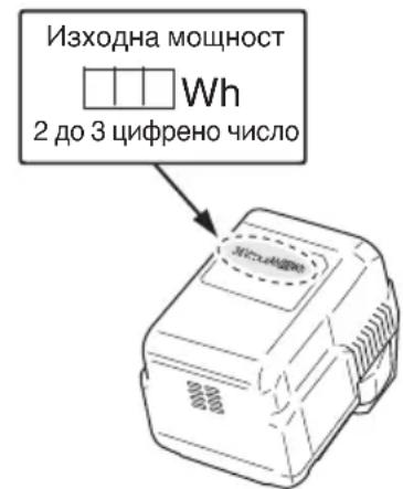
ONICAHNE HA HOMEPINAHITE ELEMENTN (Фиг. 2 - Фиг. 46)
CTAHДAPTHN AHCECOAPN
| CG36DL (LBR) | ①Баэрия(BSL3620)......................................1 |
| ②Зардно устroduстwo(UC36YRSL)......................................1 | |
| ③Найлонова галва......................................1 | |
| ④Калak......................................1 | |
| ⑤Шеб.гаячен Клич 4 ММ......................................1 | |
| ⑥17x19Комби Ктугягаячen Клич......................................1 | |
| ⑦Зашатно съкло......................................1 | |
| ⑧Ремьк за рамо......................................1 | |
| ⑨Ремьк на okоча.... ......................................1 | |
| ⑩Калak на баэрия.... ......................................1 | |
| CG36DL (NN) | ①Найlorонова галва......................................1 |
| ②Калak......................................1 | |
| ③Шеб.гаячен Клич 4 ММ......................................1 | |
| ④17x19Комби Ктугягаячen Клич......................................1 | |
| ⑤Зашатно съкло......................................1 | |
| ⑥Ремьк за рамо......................................1 | |
| ⑦Ремьк на okоча.... ......................................1 |
| CG36DL(L) (LBR) | ①Баэрия(BSL3620)......................................1 |
| ②Зарядно устroduстwo(UC36YRSL)......................................1 | |
| ③Найлонова галва......................................1 | |
| ④Калak......................................1 | |
| ⑤Шес.T.гаechен Клич 4 ММ......................................1 | |
| ⑥17x19Комби Ктугягаechen Клич......................................1 | |
| ⑦Зашатно съкло......................................1 | |
| ⑧Ремьк за рамо......................................1 | |
| ⑨Ремьк на okанbaнe......................................1 | |
| ⑩Калak на баерята......................................1 | |
| CG36DL(L) (NN) | ①Найlorонова галва......................................1 |
| ②Калak......................................1 | |
| ③Шес.T.гаechen Клич 4 ММ......................................1 | |
| ④17x19Комби Ктугягаechen Клич......................................1 | |
| ⑤Зашатно съкло......................................1 | |
| ⑥Ремьк за рамо......................................1 | |
| ⑦Ремьк на okанbaнe......................................1 | |
| CG36DAL CG36DAL(L) (LBR) | ①Баэрия(BSL3620)......................................1 |
| ②Зарядно устroduстwo(UC36YRSL)......................................1 | |
| ③Найлонова палва......................................1 | |
| ④Калak......................................1 | |
| ⑤Шеб.гаячен кюч 4 ММ......................................1 | |
| ⑥17x19Комби Ктугяаячen кюч......................................1 | |
| ⑦Зашатно съкло......................................1 | |
| ⑧Ремьк за рамо......................................1 | |
| ⑨Ремьк на okанbaнe......................................1 | |
| ⑩Калak на сьerteшитta......................................1 | |
| CG36DAL CG36DAL(L) (NN) | ①Найlorонова палва......................................1 |
| ②Калak......................................1 | |
| ③Шеб.гаячен кюч 4 ММ......................................1 | |
| ④17x19Комби Ктугяаячen кюч......................................1 | |
| ⑤Зашатно съкло......................................1 | |
| ⑥Ремьк за рамо......................................1 | |
| ⑦Ремьк на okанbaнe......................................1 |
CtaHdapTHnTe akcecoapn ca npedmet Ha npomHa 6e3 npedynpexKdene.
ДОПьЛНITEЛНИ AHCECOAPN (прдават ce OTделно)
O BaTePnA
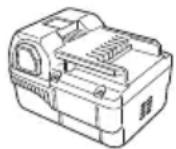
(BSL3620)
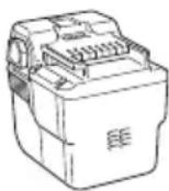
BSL3626)
EJIeKtpnuecko 3axpaHbaHe PeKeu 3b6 (CG36DL caMo)
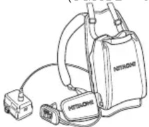
(BL36200)

3ABEJIEXHA
3a daHHn 3a onepaunnte, moJI, BnKTe pBkoBOdCTBOTO C nHcTpyKuIN 3a BL36200.
Pn n3noJ3BaHe Ha peHaeu 3b6, noJrTOBte 3a HCTaJIpaHe KaJInaKOBuDHa raKa, RaKa 3a HHTaJIpaHe OT JIbAta CtpaHa M10 u KOMNJIeHT 3a npOTNBtoEKeCT.
HaIINaKOBuHa raHa (CG36DL camo)
O HnctaInpaHe Ha raKaTa M10 ot IaBaTa cTpaHa (CG36DL camo)
HOMnJIeK3a npoTnBoteJHexc (CG36DL cMo)
3ABEJIEXHA
3a NOBuee DaHHN 3a OepauNTe, MOJI BnKTe INHCTpyKuNTe 3a KOMNJIeKTA 3a npOTNBOTeJcEeT.
IOnbJIHHTeJIHHTe aKCEcoapn noJteKaT Ha npomHa 6e3 npedn3BecTne.
ПИЛОЖЕНИА
Iopra3BaHe,IOuHCTBaHe H KocHe Ha nJIeBeJI.
N3BAHDAHE/IOCTABRHE HA BATEPNYTA
1.ИЗвадан Ha 6aTePnraTa
XBaHeTe3IpaBO KOpnyca HAtncHeTe 3aKIOUaIKNtE Ha6bATEpIraTa,3aJa I3BaINTe (BnKeTeΦIr.3).
BHIMAHNE
Hnkora He daBaTe HaKbCo 6aTePnraTa.
- NocTabaHHe Ha 6aTepeHraTa
CLOKHe 6aTePnTa, KaTo BHMaBaTe 3a NOLcHte (BHTeΦr.3).
3APEKDAHE
Ipei Da H3noJ3BaTe eJeKtpnuecknT INHCTpyMeHT, 3apeTe 6aTeepnTa KaKTo CneJa.
- BkIIOyTe 3axpaHbauuHa Ka6e Ha 3apHHOTo yCTPOyCTBO B HOHTaKaTa.
Korato 3axpaHbauNT Ka6e e CBbp3aH, INdikatopHaTa lamna Ha 3apJHOTO yCTPOcTBO ue Mnra B YepBeHo. (Ha INHTepBaJIn OT 1 cekyHda)
- NocTabete 6aTePnra Tb 3apAnHOTo ycTpoCTBO.
BkapaTe 6aTePnra Ta NbTHO B 3apAnHOTo yctpoiCTBO,doKaTo ce BNIN LInHnTa,KaHTo e nokaHaHO HaΦnr.4n5.
3.Заразецданe
Horato nocTabite 6aTepeHnTa B 3apdHOTO yctpoiCTBO, 3apeXdaHeTo 0e 3anoHHe, a INHdkatopHaTt JAmna 0e CBETN NOCTORHHB YepBeHo.
Korato 6aTePnraCe 3apeHnBJIHo, INdikatopHaTata lamna ue Mira B YepBeHo. (Ha INHTepBaJIn OT 1-ceKyHda) (BnKTe Ta6nua 1)
(1)ИндикадиHAплOTнlaJaMaNa
HnKaunTe Ha nIOTHaTajamna 6bDat Te3n KaTO nOKa3aHNTe B Ta6nua1, cnopeC bCToHNHeTo Ha 3apAHO TO yCTpoNCTBO NN aKymNaTopHaTa 6aTePn.
Ta6nua 1
| Индikаци на плотна тампа | ||||
| Индikatopната лamпа сбети лим мига в червен. | Преши зарождане | Мига | Сбета за 0,5 сени. He сбети 0,5 сени. (изгасва за 0,5 сени) | |
| По вreme на зарожданe | Свети | Сбети несякьсано | ||
| Заврышени зарожданe | Мига | Сбета за 0,5 сени. He сбети 0,5 сени. (изгасва за 0,5 сени) | ||
| Невоземно зарожданe | Мига | Сбета за 0,1 сени. He сбети 0,1 сени. (изгасва за 0,1 сени) | Повсяв в батерия лим заюустристvo | |
| Индikatopната лamпа сбети в зелен. | Рек imm Изчakвае поади пergявае | Свети | Сбети несякьсано | Пөрөлэхы сбети. 3аөрөданeto Невьзmonног (заөрөданeto ще започе сдд охлajдане на састристу). |
(2) OTHOCHO TEMNepaTpaTa Ha aKymyIaTOPHaTa 6aTePnB Ta6Iuca 2 e NOKa3aH TemNepaTpPNrT dIana3oH 3a 3apeJdaHe Ha 6aTePnra; 3aRpeJIte 6aTePn TpRbBa Da n3CTINat Ppei npe3apeKdaHe.
Ta6nla 2 Tempeatypen dnaana3oH 3a npe3apeJdahe Ha 6aTeprn
I3BaTe 6aTepeNn3BbPbBaHe Ha BcKaKbMOHTaK.
1.ИнсталupaHe Na BbTpewHaTa pBHOXBaTHa (Фиг.7) (CG36DL(L),CG36DAL(L)camo)
(1) OTCpaHete 6oIToBete M6 × 43 (2 6poj).
(2) MoHTnpaTte BbTppeShHaTa pbKoXBaTKHa Ha rIaBHaTa Tpb6a, taKa Ye da Ce HAMnpa cpeu KapTepa.
(3) NocTaBete npKpenBaunia MexaHn3bM Ha pkoxBaTKata B DOJIINH KpaI Ha rIaBHATA Tpb6a Iro fHKcapaIte cTaNIO C nOMOHTa H a 6oITOBe M6 x 43 (26p0r) mM6raIKN (26p0r).
3ABEJIEXHKA
IocTabete BbTpeHnata pBkoXBaTKa Ha MCTO, oCnrypraBaaso do6po 3axBauahe.
BHIMAHNE
MOnTnpaIte BbTpewHata pBkoXBaTKa npabNJIHO n CTa6NJHO, KaKTO e yKa3aHO B INCTpyKcUNTe.
Ako He nocTaBeHa npabuHNO HnCTa6HNO,MOKe Da naHe n da npuHn HapaHBAhe.
- MoHTnpaHe Ha BeNoCHneH BnD pBHOXBaTHN (ФИR.8)
(1)ИзпольвайкОсичуреня 4 MM Weec.T. raeунOTCTpaHETe YeTnpHTe 60ЛТа, KOnTO ca BpeMeHHO3axBaHaTN KbM ChObaTa Ha pblkoXBaTHaTA (A).
(2)ПркpeneteЯснata ctpaHa Ha pkoxBaTkata, KOrTo CbIbPka loCTa, И ЛВаТа ctpaHa Ha pkoxBaTkata I CneI TOBa BHNMaTeJIHo Пркpenete ChO6aTa HApBHKaTAtA),ИЗпOL3ВaHn YeTnpIte 6oI Ta.
3A6EJIENKHA
PpInKpeIeTe IaBaTa n DcHata pBHOxBAHTN BIOJIOJOHeH, OCHyprBaAio Do6po 3axBaJauHe.
BHIMAHNE
MOnTnpaIte npabHIO n CTaBnHO JARbAta n DcHAta pKoXBaTK, KaTTo e yKa3aHO B HcTpyKuNTe. Ako He e noCTaBeHa npabHIO nIN CTaBnHO, MoKe da naHe n Da npuHHn HapaHBAhe.
3.ИЗпьваеHa rnaBhaTa Tpb6a(Фиг.9)
(1)Ocbo6oTeJeIOCTa3a3actOnOpBaHe,3aJaNo3BOJInTe H3PbBAHETOHaTlaBHaTa Tp6a.
(2)Изпь Hedge Гльната Трба B MaKcHMaJHa CTeNeH, DOKaTO Chyete Da UpaKHe.
3ABEJIEXHA
DnIraTeJIaT HMa Da pa6oTn DOKaTo INaBHaTa Tp6a He e N3PbHaTa MaKcHMaJHO.
Korato hatuchete 6yToHa 3a 3axpaHbaHe, YepBeHaTa CBETInHa 3a 3axpaHbaHEto ige Mna 6bp30.
(3) Cnei n3nBbaHe Ha rnaBHata Tp6a DoKaTo UpaKHe, npOBepTe DaJIH OTBOpBT Ha KyTHraTa Ha DbpKHa e NpOpaBHeN C OTBopa Ha rnaBHata Tp6a N 6IoKnpaTe IocTa 3a 3actOnopBaHe 3a Cta6uIHO fHKcnpaHe Ha rnaBHata Tp6a.
4.Инсталпанои Канакa(Bинг.TeФиг.10и11) INPEДУПЕХДEHNE
YBepeTe ce, Ye cTe HcTaHpaN KaNkA B npedHa3NaHeHOTo 3a ueTAMrTO. Hecna3BaHeto Ha TOBa npedynpexHene MOKe Da DOBeDe Do HapaHbAe OTeTnKambHn.
3ABEJIEXHA
I3noJI3BaIte npedocTaBeHn IeCT. raeueH KIOU 4 MM 3a INCTaIIpaHe.
(1)ИзлбайтpeпeдocтавенясD5camohapra3baBnHT 3a INHCTaJInpaHe Ha HOKa B Kanaka.(Фиr.10)
(2)Подравнente ДваТОВОРА BСКOBаТа Ha KAnaKa N KaNaka N BKapAte DBA M6 × 25 WeCt. CBp3BaUH 6OJIta. (СКOBаТа Ha KAnaKa e MOHTnPaHa B KyTЯТа Ha DBuRaTeIa.)
(3) NocTaBete DbpaHa Ha KaNaka OT DoJIHaTa CtpaHa Ha KaNaka H3NoJ3BaIte PpeOCTaBeHn IeCT. Raeyeh KIOU 4 MM 3a PnCtTgAHe Ha DaBaTa M6 × 25 WecT. CBbp3BaUn 6oJTa, DOKaTO He 6bDaT npabNIHO 3aTeHaTH.
BHIMAHHE
O BHMaBaIte Da He Ce IopeKeTe C HOHa BBB BbTpewHaTa YacT Ha KaNaKa.
O MoHTnpaIte npabNlHO n Cta6nIHO KanaKa HoxKa, KaKTo e NocOueHO B INHCTpyKuINTE. Ako He ca npkpeHen npabNlHO n Cta6nIHO, Te MOKe Da N3JIa3AT N da npuHHaH HapaHbAHe.
5.Инсталпа He pexeun36 (He3aIbHHTeH aHcecoap) (CG36DL camo)
IPEdynpeKDEHNE
O Ipei Da HcTalnpate peKeu3b6, He 3a6paBnTe Da cI0KHTe KaNaka Ha 3b6a, HocTe De6eIn PbKaBnU IN B3eMeTe BCNUKN DpyrH Heo6xOdMn IpeDna3HN MepKn.
O Ipei Da HnctaInpate peKeuIg 3b6, npoBepTe BnMaTeJIHO n Ce yBepTe, ye He e HaNyKaH, DeOpMnpaH NIO dpyr HauHH NOBpeDeH.
O PnHCTaInpaHe Ha peKeueyra 3b6, nbpBPO npKpeNete HerOBn KaNaK, ObezonacBaNk OTbopa B CpeDaTa Ha peKeueyra 3b6 KbM npoeKpyra Ha MexAHn3Ma Ha PhaHeca, TaKa Ye peKeueyra 3b6 Da ce BMeCTBa B KaIInakOBnHaTa rAka N CEHTpaJHaT My Yact Da He ce nn3ra. (BnXteΦnr.21)
CneMOnHTnpaHeHapeKeeuN3b6,He3a6paBnTeJaOTCTpaHNTeIWeCT.RaeueH KJIouN KUxN Tpb6eH RaueH KJIou.
Ako raikata 3a HcTaInpaHe OT IaBaTa CtpaHa M10 nn KaIIaKOBnHaTa RaKa NOKa3Ba PpN3Haun 3a n3xa6raBe nn n3TpnaHe, CMeHeTe rC HOBa RaKa 3a IHCTaInpaHe nn KaIIaKOBnDa raKa.
(1) BkapaTe MexaHn3Ma Ha ΦlaHeuBa B KyTnaTa Ha dBurTaTeJa. B TO3N MOMENT KpIIOTo Ha MexaHn3Ma Ha ΦlaHeua Tpr6Ba Da e CpeUy KyTnaTa Ha dBurTaTeJa. (Фиr.18)
Блгарский
(2)3a da HnctaInpate pekeun 3b6, BkapaTe OCnrgpeHna WeCT. raeuen KInou B OTBOpHTe Ha MexaHn3Ma Ha fanaHeua Ha kyTnraTa Ha dBnraTei N B nocJeIOBaTeIeH pe npKpeIeTe pekeun 3b6 n KaIINaKOBnHaTa raKa.(Φnr.19) MoTHnpaTe pekeun 3b6ype3 3abbpTahe B yka3aHaTAtOT cTpeJIkata nocoka.
3ABeJIeHHKA
CnE cnpyhOTo npTgAne, perynnpaTe taka, ye raHkata 3a nHctaInpaHe OT IaBata cTpHa M10 da MOHe Da 6bDe paXla6eHa nOCBO6oDeHa. Hen3PbJIHeHHeTo Ha rOpEnocOeHTo MoHe Da npUHNi DeOpMaun HA MexAH3Ma Ha fNaHeua nn NOBpeDa.
(3)ПозиюнраиTe 3akpbглeHata ctpaHa Ha raHkaTa 3a ИнсталпаHe M10 taKa, Yeда e cpeSu KyTnIraHa raeuHnЯ KJIIOU, И сLEД TOBa 3aTeHete cTa6NJIHo. (Фиг.20)
(4)Поверетен ce yvere,чpeхшгт 36 e npabuHOMHTnpaH.(Фиr.21)
6. Истелега на ремьна на pamOTO Изплбайта вkomбионця сbaтугь BSL3620.
PNEpyPENKDEHNE
He 3a6paBnTe da npnKpeNITe peMbHa Ha pAMTo nO haunH, no3BOJIyBaU, npaBnIHOTo HOceHe Ha TpIMepa 3a TpeBa.
Ako CHTate, Ye INHCTpyMeHTbT He pa60TH HOpMaJIHO, N3KIIIOUeTe BeDHara DnBraTeJRA, N3BaJeTe 6bp3O-OCBO6OXJaBAaTaCkObaHa peMbKa Ha paMTo n OTCTpaHete INHCTpyMeHTa.
BHIMAHNE
Ako He noDbpxaTe HnCTpyMeHTa npu n3dbpNaHe Ha 6bp3o-ocbo60KdaBaun KOLaH, ToJ MOKe Da naHe N da pnuHHn HapaHnBaHe nnIOBpeHa. PnpDbpaTe rnaBnata Tpb6a c edHa pbKa,doHaTo n3dbpNaBe Tc pyrata.
O Ybepete ce, Ye yHKnraTa 3a 6bp3o OCBO60HdaBaHe pa60TH HOPMaIIHO, npei Da 3anoHte da pa60Tne.
(1) NocTaBeTe peMbKa Ha paMTo, KaKTo e noKa3aHo Ha Phr.12 (3a yNoTpe6a n3BbH Ebpona, BnKTe Phr.14) I ro npKpeneTe c OKaHaun eneMeHT Ha INCTpyMeHTa. PeryIinaPe mbKa Ha paMTo Ha noXoJaHa dJbnHa.
(2) 3a Da OTCTpaHHTe INHCTpymeHTa OT peMbKa Ha pamOTO, NOIbPkaIte INHCTpymeHTa, KaTO 3aDbPnHTe rIaBHaTaTpb6a C eHa pbKa H N3NoJI3BaTe dpyrata, 3a Da N3DbPnATE 6bp3O-OCBO60KdAbaunpeMbk, KaKTo e NOKa3aHO Ha Phr.12 (3a yNtpe6a N3BbH EBpona, BnKTe Phr.14) 3a OCBO60KDaBaHe OT cKO6aTa.
(3) 3a CTIrahe c IeHTa Ha INHCTpyMeHTa, BkapaTe CKO6aTBA OKaYBaUIM MEXAH3bM NIOCTaBeTe 6bp3OOCBO6OJDAbaUa CKO6a HAD KyKaTa N B WnPOKNr OTBOP Ha CKO6aT. (ΦIr.13) (3a ynoTpe6a n3BbH Ebpona, BNKe T EInr.15) BHIMATEJIHO n3DbpNaIte peMbHa Ha paMOTo, 3a da ce yBepHe, Ye e npabNIHO NOCTaBeH.
PpnoJHMM HaJIHOHB HHyP
3. PerylnpaHe Ha IbIHHHaTa Ha IHHnraTa
3aBbptete n onpeTe haJIIOHOBA tIaBa Do 3eMraT. HaJIIOHOBNr peMbK e N3TeIeH OKOLO 30 MM OT eDHO HApR3BaHe. (Φn.r.24)
Cbto taka, moheTe da n3nBHeTe haioHOBn peMbK c pue. B TOBa BpeMe DnRaTeJr Tp6Ba da e HantbIHO cnprH.
NotbpeTe 3nBbaHeTo Ha JINHnTa c 30 MM yBeJIuYeHnIype3 "HapraBaHe" n,OCBO6OJdaBaHe" Ha 6byToHa BdbHOTo, DOKaTO N3DbPnBaTe KpaIuTaHa JINHnTa Ha HauNoHObata TnaBa. (ФИR.25)
O POnxOJaHa DbJnHa Ha NaHaiHOOBnpeMbK
POnxOJaTa TaBnKHa Ha pEmbKa npu yNoTppe6a Ha HnCTpyMeHa e 90-110 MM. N3nBHeTe pEmbKa Do POnxOJaTa TaBnKHa.
4.CMaHa Ha HauHOHpEmbK
(1)IopDrTBeTe 4 M opuHnHaJIeH HaJIHOHOB peMbK BΦnr.22.(KoD No 335235)
(2)HaTnCHeTe CpeUyNoJHnIte fHKCaTopn n cIeI TOBa CBaIeTe KanaKa OT KyTnIraT. (ФИг. 26)
(3)ИЗbaTeMaKaPaTaOTKуТЯ.(Фиr.27)
B cnyuha, ye hma ocTaHa haJIOHOB pembK, OKaYeTo B MExAHN3MNTe H CJeD TOBa OTCpaHETe MaKaPaTa.
AHO HauHIOHOBnT peMbK He ce n3nBa, KOraTO mHa DOCTaTbHIO OCTaHaI HaNIOHOB peMbK, IIN npn CmHa Ha HauHIOHOBnPeMbK (KoD No 335235), HABNIte ro, CbrlacHO CJIeHaTa PPOeDpya.
(4)Ocbo6oTe OKOIO 150 MM OT HaHNOHOBnI SHypOT BaTa Kpa, CbHeTe CpeHaTa Yact N npKpeTe KbM KyKaTa HA MaKapata.CJeToba 3aBNITE Hhypa Ha MaKapata B yKa3aHATA OT CTpeNkata NOcOKa, KaTO BHIMABATE Da He FO KpbCTOCate (Fnr.28,29).
(5)OctaBeTe OKoI0 100 MM - 150 MM HaJIOHOB HHyp HeHaBNT, OKaHTe N IOcHpypeTe peMbKa B orpaHnHTeJI. (ФИr.30)
3ABEJIEXHA
He npecuHaTe HaJIOHOBnpeMbK npn 3aKpenBaHc My B orpaHnUteJI. (Phr. 31)
(6) NoppaBHeTe no3nUraHa orpaHnUteIa I BODaHa Ha yXOTO Ha peMbKa n CJIeD TOBa NOCTaBeTe 6yToHa B KytTnTa.
Ocbobodepe pmbka OT orpaHnHTeJ KATO eHOBpemEHNO npndbpKaTe Jeko MaKapata N cJeT TOBa npokapai Te JINHnTa Ipe3 BODaHa Ha yxOTo Ha peMbka. (PhiR. 32)
(7)HaTnCHete H3aTBOpTe ΦHcCaTOPHe Ha KyTnTa B 6JoknpaunTe OTBOpHa KaNaKa. (Φnr. 33)
PDEyPExKDeHNE
PpOBepeTe H ce yBepeTe, Ye fHKcaTopHte ca 3dpaBO 3aKpeHn B 6IoknpuNTe OTbOpN.
Pa60ata c HhCTpyMeHT, DOKaTO YactHte He ca CTa6uHNO npnKpeHn 3aeHNO, MOKe Da DOBeDe Do 3JIOJOLyKn Hn HapaHbAHnO TJeTua YaCT.
(8)ИздьрnaitepeMbha,Taka QueHaHЯMa HeH3NbHaT auctи cnei TOBa cpeKeTe peMbka Do ydJIHeHa IbJIHHaOT 90 MM-110 MMcHOxNt.(Фнr.34)
PABOTA
Kactpehe Ha TpeBa
PNEyPENKDEHNE
He pa6oTeTe c HnHcTpymeHa Tnpes HOnTa Hn npn louMeTeOpOJIoRyHn ycIOBn CbC cna6a BUnMoCT.
He pa6oTeTe c HnCTpyMeHTa, KOrato BaJIu nn HeNoCpeDcTBeHO CJeI DbKJ.
O Hocete noDxOJnO oByBKn 3a npedOTbpaTbaHe Ha nOxIb3BaHe, KOeTo MOKe Da HApUu PaBHObecneTO Bu n da naHHeTe.
He n3noI3BaIte HnCTpyMeHTa Ha CtpbMHN CHIOHOBE. Pn noPra3BaHe Ha TpeBa HA CKIOHOBE, KOHTo He ca MHOro CTpBMn, NOpr3BaTe, DOkATO CE pNDBHKBaTe KbM Bbpxa.
O NocTabete JIChata cn pKa Bbpy pbKoXBaTKata, a IaBaTc n pKa Bbpy BbTpewHaTa pbKoXBaTKa I XBaHeTe 3npabo.
BnHmabAte Da He npMeCTHe HauHObata rIaBa npekaJIeHO 6JIn3O Do KpaKaTAtn.
He BnraTe HaJIOHObTa TnaBa HAd BaWeTo KOJHNO BpeMe Ha P3aHe.
He n3noI3BaIte HnCTpyMeHTa, KbJeTO HaJIIOHOBaTa rnaBa MoHe Da BLeSe B KOHTaKT C KaMbHn, DbpBO N dpYr npenTCTBn.
HaIIOHObAra IaBa MoKe Da npuHn HapaHbAhe, KOrato npOdbJIkaBa Da ce BbpTn Cnei N3KIOUbaHe Ha Dbratela. Korato yCTpoNCTBOTo e N3KIOUeHo, yBepTe Ce, Ye HaIIOHObAra IaBa e cnpraJa, npedn da CBaInTe yCTpoNCTBOTo.
He n3no3BaIte HnCtpymeHa pa3ctOHHne noMaJIkoOT 15 M OT Dpyr YOBek. KoraTo pa60THe 3aeHNo C HAKo Dpyr, ce DpbXte Ha pa3ctOHHne NOBee O 15 M.
HaIrahe Ha 3b6a MoKe Da ce noLyuH, KOraTO BbptTnHT Ce 3b6 BnE3e B KOHTaKT C TBbpD npeDMET B KpITnTuHaT a Oblact.
MoKe Da Bb3HnKHe onaCha cnTyauZna, npuynHbua Ca rpy6o n3TlackBaHe Ha zIaIOTO yCTPOJCTBO n Otepatopa. Ta3n peakunCe hapnuHa Hnrahe Ha 3b6a.Bpeyntat Ha ToBA, onepatoBt MoKe da 3ary6n KOHTpol Bbpxyypeda,KoTe Da npuHHn cepno3HO nn PhataHn HapaHbaHe.Ha JraHe Ha 3b6a e noBepoTHo Da ce Cnyu B o6laactn, KbTeTo e TpydHo Da ce BVn MaTePnAJa 3a P3aHe.
1. NocTaBete 6aTepeRrTa Hato BHMaBaTe 3a HeHHTe NOJIHOCh.
2. BhInouTe HnCtpymeHTa. (ΦnR. 35)
HaTnCHete 6yToHa 3a 3axpaHbAHe Ha KyTnTa, 3axpaHbAHeTO Ce BkIIOUBa I JAmnata 3a 3axpaHbAHeTo Ha pBkoXbTkata CBeTBa B YepBeHO.
O NobTOpHTo HaTnCKaHe Ha 6yToHa n3KJIouBa 3axpaHbAHeTo Hn3rACBa IaMnTa B YepBeHo Ha pBkoXBaTKaTa.
[Фуннцяза abTomatuHOnинluOyBaHe]
Korato 3axpaHbAHeTo e BkIIOyeHo, Ho IocTbT He ce n3IOJI3Ba 3a eHa NMHyTa, INHCTpyMeHTbT ABTomATuHO ce n3KIOUBy. 3a da BkIOUHTe INHCTpyMeHTa OTHOB, HAtNCHEte NOBTOHO 6yToHa 3a 3axpaHbAHeTo.
IPEDyPENPEXDAEHNE
Hnkora He octabTne HNCTpyMeHTa BkIouen. ToBa MoKe da npedn3BnKa 3JIOJyKa.
3. Pa6ota Ha IocTa H cnIpaHata (Phr. 36)
3a da 3aIOUHe BbPteHTo Ha peKeIeN3b6 CBKIOUeHO 3axpaHbAHe, H3DbpNaIte IocTa, KaTO CbIeBpeMeHHO npITnCKaTe 3aKIOUBaIINIOCT.
PnO tnyckane Ha loCTa, cnnpaaykata ce 3aedcTba 3a 1-3 cekyHdn, cnnpaIKn BbptHeTo Ha peKeuHa 3b6. YBepete ce, ye cnnpaaykata paobTu HopMaIHO npedi Da n3NoJ3BaTe HhCTpyMeHTa.
4. PerynaTop ha ckopocTtA (ΦnR. 37)
Perynatopt 3a npomraHa chopocTtHa BbpteneB 0xbataOT 5800-7000 mH-1e ocnrgen Ha kytnraTa. 3aBbptete uphipe6nata no nocoka Ha yacobhikOBaTa CTpeJka, 3a da ybeJIuHTe chopocTTHa 6paTHo Ha yacobhIKOBaTa CTpeJka, 3a da HA haJaNTte.
5. Kactpene Ha TpeBa
XbaHete dpbHKHaTa OTROpe, HATNCHEte loCTa 3a 3actONOpRAHe n dpbnHete loCTa, 3a da 3anOHe da ce BbpTn peKeuata rnaBa. (MnR.38)
Ocbo6oTe IocTa, KOrato 3aBbPwHte NOpra3BaHeTo n CnpTe DBrIgATEJI.
O NocTaBete BaunnaLeu Bbpxy pbKoXBaTHaTn XbaHete c ocTaHaJIte npbCTn. (39) (CG36DL, CG36DAL camo)
O NocTaBete Baunnae Bbpxy BbTpneHaTa pboKoXBaTHa n XBaHTe C oCTaHaJIte npbcTn. (40) (CG36DL (L), CG36DAL (L) camo)
3aemeTe no3nui, KOTo yIeCHBa npuBnXBaHeTO.
[TexHHnH 3a nOdpra3BaHe Ha TpeBa]
He BbptTe Tpb6aTa, a n3noJ3BaIte 6eApTa, 3a da npdBnHInTe HaJIOHOBA TaIaBa XOpN3OHTaJIHO OT DaCHO HAIJIBO B apKOBuHa φOpMa, DOKaTO BbPbNTe Hanpei N3noJ3BaIte JIABa CTpaHa Ha HaJIOHOBA Ta IaBa 3a NoDpR3BaHe Ha TpeBa. (Φnr.41)
ПРЕДПАЗНМЕРКИ 3A PAБOTA
PpOdbJIHHTeJHa pa6oTa
To3n INHCTpymeHT e cHa6dEN cBc 3aunTHa Bepnra npOTNB ppeprbaHe, KOJTO npeDna3Ba eJeKTPoHHnTe Yactn, KOHTPOJInpaun npe3apeJdaauata ce 6aTePn. Pn npOdbJHKNTelHa paOta 3a NOpR3BaHe, TEMNepaTypata Ha INHCTpyMeHTa ige ce NOBUnn Iue 3aJeCHTBa 3aunTHaTa Bepnra npOTNB npERpaBe, KOJTO 0e rN3KIOUHy. Ako TOBa Ce cLyu, OCTabeTe INHCTpyMeHTa Da ce OXlaDu 3a N3BecTHO BpeMe. Korato TemnepaTypata CnAdHe, 5e 6bDe Bb3MOxHO OTHOBO Da N3NoI3BaTe INHCTpyMeHTa. Korato npe3apeJdaauata ce 6aTePnRA Tp8Ba Da ce CmEH npn npOdbJHKNTelHa paOta, OCTabete INHCTpyMeHTa da NoOHne 3a OKOJO 15 MInHyTu.
3aunTa cpeu npetOBapBaHe
To3n INHCTpyMeHT e cHa6dEHN CbC 3aunTHa BeprA npOTNB ppeTOBapBaHe, KOrTO ppeIa3Ba EJIeKTPoHHTe YAcTn, KOHTPOINHpauN INHCTpyMeHTa. Pn HENPEKbCHaTO ppeTOBapBAHe NO Bpeme Ha pa60Ta NO NODPRA3BaHe (3aCtONOPRABaHE Ha HAIIOHOBAta rnaBa n dp.), 3aUNTHaTA BeprA cpeUy ppeTOBapBaHe N3KIOUBy DnURateJ. Ako TOBa Ce cLnyu, N3KIOUte 3axpaHBAHeTO i CLeD TOBa pa3peWeTe np6leMa, npedIN3BnKAL npETOBAPBaHETo. INHdkaTOPbT Ha 3axpaHBAHeTO MIRA, aKO IocTbTe HaTHcHAT CneI CnIPAHe Ha DnURateJIA (BNHTe CTp.294,3A INHdkATOPHATA JAMNA HA 3AXPAHBAHETO). 3axpaHBAHeTO ABTomTuHNo ce N3KIOUba, aKO INHdkaTOPbT Ha 3axpaHBAHeTO MIRA No-dbIro OT 5ceKHydn. AKO TOBa Ce cLnuu, pa3peWeTe np6leMa, npedIN3BnKAL npETOBAPBaHETo i CLeD TOBa BHIOUte 6byToHa 3a3xpaHBAHeTO, 3a da IN3NOI3BaTe OTHOBO INHCTpyMeHTa.
Ipehahe Ha Hctpymenta (42)
BHIMMAHNE
O Tcpanhe 6aepnra H n3no3BaTe KanaKa Ha peKeun 3b6, 3a Da ro npedna3nte npi npehacrHe Ha HHCTpymEnTa.
IpeHacraHTo Ha HnCTpyMeHTa 6e3 IpeBapntHo NOCTABrAHe Ha KanaKa Ha peKeuHa 3b6, N3laRa YOBeWKOTo TIAHO NaCHOC, KOETOMe Da DOBeDe Do HapaHBAhe.
Hocete HnCTpyMeHa c pue n dpbKTe peKeunr 36 daJeU OT TAnTo.
OПи пибиранеHa rnaBHaTa Tpb6a,BHIMaBaNTe 3a HacoueHЯ Край nДа He 3axBaHete npbCTnTe Cn. (CG36DAL, CG36DAL (L) caMo)
Ocbo6oTe loCTa 3a 3actOnopBaHe n npnbepete IlaBHata Tpb6a. 3akIIOyTe loCTa 3a 3actOnopBaHe, DOKato PPOeKuYTA CTnHRe IlaBHata Tpb6a. Ta3n npOceDypa N03BOJBA Da CBeDeTe INHCTpyMeHTa B KOMNaKTeh pa3Mep.
Tnabhata Tpb6a MoHe da 6bJe npnbpaHa BbB BCaHO noLoKeHne. N36peTe noXoJa7a DblKnHa 3a HocHe n cbxpanHe.(CG36DAL, CG36DAL (L) caMo)
ПОДДРьЖКА И ПЮВЕРHA
BHIMAHNE
IpeuHnCneKunu HIn NpDpbXka H3BaTe6aTePnTa.
- NpOBepete CbCTOAHHeTo Ha HauHOHObTa IaBa HauHOHObTa TnaBa Tpa6Ba Da ce npOBepraPeIOBHO. 3HOceHa nn CyneHa, HauHOHOb TaNaBa MoKe da Ce
N3XJy3n NIN Da HamaJIeΦeKTHBHOCTTa Ha DBNrAteJIa N da Tn3rOpN.
3ameheTe n3HOceHaTa HaIIOHOBa rIaBa C HOBA.
BHIMAHNE
N3NoJ3BaHeTo Ha HauJIOHOBA rIaBa, YHnTO BpBX e H3HOceH NIn CuypeH, e OnaCHO. 3aTOBa J3ameHeTe C HOBA.
2.ПоверяBaite BnHTOBete
Xla6abNTe BnHTOBe ca onacn. IpOBepaBte rpeoBHO n ce yBepaBte, ye ca 3aTeHaTH.
BHIMAHNE
N3noJ3BaHTo Ha To3n eJeKtpnueckn HnCTpyMeHT pa3Xla6eHN BnHTObe e N3KIOUHTeJIHO ONaCHO.
3.ПроветаHa Kap60HOBNTe YETKn (ФИг.43)
MToopbT 3nOJ3Ba KAp6oHOBu YeTKu, KOUTo Ca KOHCymaTHB. TbN KaTO CUNHO N3HOceHN KAp6oHOBu YeTKu MoTa Da DOBeaT Do npo6JIemn C DnurateJIa, CMeHrIte Tn C HOBu, KOrato Ce N3HOcRt, ININ Ca NoHTN N3HOceHN. OCBEN TOBa, BInHaN NOdNbPkaHTe KAp6oHOBuTe YeTKu YnCTNu CE yBepeTe, Ye Ce NlNb3rAT CBO6oNDHO B DbPkaHTe.
3ABEJEKHA
Horato CmeHrTe Kap6oHOBnTe YeTKn C HOBN, yBepeTe ce, Ye n3NoJ3BaTe Kap6oHOBn YeTKn Hitachi o KaTaoKeH No. 999068.
I3MepeHO A-tpeTeJIeHO UyMoBO HnBO: 85 dB (A)
H3MepeHO HnBO Ha A-tpeTeJIeHO 3ByKOBO HaJIraHe:76 dB (A) HeToUHocK:3dB(A).
Hocete aHTnfoHN.
O6u n cToHocTn Ha Bn6paunn (BeKTopHa cyMa) onpeJeIeHNcBrlaCHO EN50636-2-91.
CToHocT ha reHe npaHnTe Bn6paunu aH, w = 4 M/ceK2
HeTOuHOCT K=1,5 M/ceK2
IeknapaHte 06u CToHocTu Ha Bn6paunn ca N3MEpeHH CbflacHO CTaHapTHHe MeTOU HauN3NTBaHe N MoT a 6bDat N3NoJ3BaHn 3a CpabHeHne MeKdy pa3NIuHHTe INCTpyMeHTn.
OcbEN TOBa cToHOCHTe MORaT da ce H3NoI3BaT 3a npedBapNTeHa OueHka.
PDEyPExKDeHNE
Bn6paunnte no BpeMe Ha DeiCTBnteHa ynoTpe6a Ha HnCTpyMeHTa MoTa Da ce pa3JInuHaBAT OT DeKnapnPahnte O6u CToHOCTH B 3aBNCMOCT OT HaUNHa HA N3N0J3BaHe Ha HnCTpyMeHTa.
O Mepknte 3a 6e30nacnoct Ha onepatopata Tp6ba da ce 6a3npat Ha OceHka Ha Bb3dEICTBNETo B peaHn ycIOBna (KATO CE B3EMe PpeBnD UeHNr pa6oTe HIKbI - BpeMeTO, Ppe3 KOeTO ypeBt E HATOBapeH nn pa6OTn Ha npa3EH XOD, IN BpeMeTO, Ppe3 KOeTO e n3KnIOueH).
OZNAKE
UPOZORENJE
Ovde su prikazane oznake koje se koriste na masini.
Postarajte se da razumete njihovo značenje pre upotrebe.
Hnue HabeedeHO CMBOIN, Aki 3a3HaayoTbCn Ha npctpoi. Nepw hix HopncTyBaTHcN npctpoeM, BN NOBHHI p0syMitn ix 3HaueHH.
| CG36DL / CG36DL (L) / CG36DAL / CG36DAL (L): AkymylarTopHH TpIMMep | |
| Почитыte Bci npabnila 6e3neHn ta Bkazibn. HeBHKoHaHnЯцх npabnil ta iNCTpyKuzi moJHe npin3BeCTndo ydapny cTpyMOM,poJekzI ta/a6o cepHoz3hoi TpABym. | |
| Завдян користугеся засобамн дя захису очey. | |
| Завдян користугеся symonorlinhaJIbHIMn HabuShNKamn. | |
| Оберiate iNCTpyMeNT bID BOJON. | |
| Стжente 3a TIm,zz6 no6no3y He 6bylo stopohnix oci6. | |
| Виимаite 6batapeU,napsh nIX pergulovatn abo YNCTHTN iNCTpyMeNT qY 3aJIshHTN IYoro 6e3 DoTJMy Da Hb-8KIN nepoiD uacy. | |
| Лше Дд КраiH EC HE BHKndaite eJeKTPnHi iNCTpyMeNT i3 no6yTOBIMn Bixxodamn! 3rJIO EByonecBkoI DnpeKTHBn 2002/96/EC pro Bixxodn eJeKTPnHO Ta eJeKTPnHOrO Bnpo6HnTBA i II 3anpoBaJHEnHra 3rJIO MlcZebnX 3akOHIB, eJeKTPoIHCTpyMeNTn, rki BicJcIyJHKInIpo6OuHn CTPOK CIId yTNl3yBatn OKPemO i NOBepTaTn Do yCTAHOB, lso 3aIMaOTbcEKOJIOTHQIO nepep6bKOIO 6puyTx. | |
| Ретьно O3HaIOMTeCЯ i3 BHKlaDeHIMn daji npabnilamn TexHikn 6e3neKn Ta nopepeJHKENHMn i 3aBxJdi IX doTPmUyTECb. HeDbale a6o HeJaLeJHNe KORISCTyBaHnna PnscTPOe MoJce npin3BeCTn Do cepNo3HOro TpaBMyBaHHa 6o Cmepti. | |
| ОзнайомТeСя 3ycima nopepeJHKENHMn Ta BHA3iBKMn, 3a3NaYeHIMN B zuBOMy Noci6HnKu a6o 6e3nocepRednbo Na npin3PoI, i 3aBxJdi IX doTPmUyTECb. | |
| Ha cac KOPnCTyBaHnЯ npin3PoE M 3aBxJdi OJraaTne 3axnChi OkJyRpn, 7oJOM Ta 7umOnorJIHaJIbHI HabuShNIK. | |
| ДITN, iHsiЛЮДn ta NOMiHKN NobINHn i 3hAxODHTNc Ha BiDcTahi 15 M BID npin3PoI. RaKZO xTOCB 6yde Do BAC Na6blnKaTncs, odpa3y BVMNKaIte npin3pi i pi3aJIbHn MexaHl3M. | |
| OstepiraTecRa BIDKnDaHnЯ pemedetib. | |
| Max 8,000 min' | BidobpaKae maKcimalbHy shBnDnictb bAlv. He BVKOpNCToBvIte pI3aJIbHn MexaHl3M,Якso Myoro MaKcimalbHa shBnDnictb obepTaHnЯ MeHsa 3a 7bNdkicTb obepTaHnBaIy. |
| 3a Heo6xIdnOcti (HapnKlnd,пд чac 3bipahnry pI3aJIbHOrO mExaHl3My) сIД BHKOpNCToBvBAtn pyKabNi. |
c)Пдчacpo6OTn ABTOMaTHHMM IHCTpyMeHTOM He nIpyncHaTe Do ce6e diTei npocTo 6baiaOuHx NOINBHTNcH Na BaWy po6Oty.
Hkuo Bac BiBbONlKaTHMyTb, Bn MoKeTe BtpaHTN KOHTPOJIb HAD IHCTpyMeHTOM.
2) Be3neKa eJekTpponpncTpoIO
a) ⅢtenceIbHa BndeJha aBtOMaTHHOro IHCTpyMeHTy MycHTb NiIXoAHTN Do PO3eTHNeEJIeKTPoMEpeHi.
Hikon HINHIM YHOM He 3miHOte BnDEhky. He KopNCTyTEcH KOHNH NacadHAMn- aadantepaMn dIra 3a3eMLeHnx ABTomaTHHNX IHCTpymENTIB.
He3mHeni wTeNceIbHi BnIeIKN Ta BiIDNoBIdHi IM pO3ETH 3MeHsuOTb pu3NK ydpay eNeKTPOCTpyMOM.
b) He TopkaηTecr TlOM 3a3eMJIeHn X npEμmTeiB a6o NOBepxOHB, TaHnx YK Tpy6n, 6aTaapei onaJIeHHI xOJIoHNbHHN.
Akuo Bu TopKHeTcTINOM 3a3emIeHOrOpneMety,ue 3bIbWye pN3NK ydpy ctpymom.
c) He donychaite, 06 ha aBtOMaTHHi IHCTpyMeHTN noTpannAIOu a6o BOJORA.
Boa, kna notpannla do aBtOMaTHNHOIhCTpymeHTa, nIBNcye pn3NK yapy cTpyMOM.
d) 06epenno NOoBbTecra 3i wHypom. HikoN He Hecitb iHcTpymeHT Ha wHpyi, He BOIOuITb Noro 3a wHyp i He BNTraIte wTeNCelbHy BnDElHy 3 po3ETKn, TARHyUH 3a wHyp.
Bepenitb uhyp BiD tenla, oni, roctpxn nobepxohb ta pyxomnx deTanei.
NoKoJKeHia 3aNlyTaH iHypn 36iNbSyIb np3nK ypaKeHH eneKTPOcTpyMOM.
e) Ppaiooun ABTomauHm iHCTpyMeHTOM npocTo He6a, HOpNCTyIteCra NOOBHyBaayAMn, npctocobAHMN dna 3actocybaHH npocTo He6a.
HopncTyBaHHa Hhypom, npncTOcOBaHm do KOpNCyBaHHn pOcTo He6a, 3HNKye Pn3NK ypaKeHHA CTPYMOM.
f) Hhio He yHnHytn po60Tu y BOJoromy cepeoBnui, HOpNCTyntecy DHepeIOM HnBleHHn i3 npNCtpoem 3axncty BiD 3aMHKaHH Ha 3eMJIIO.
Pnucpi3axhctyBid3aMkaHHHa 3eMIO 3HHyE pN3NK ydapy cTpyMOM.
3)Oco6ncta 6e3neka
a) He Btpaayte nHbHocTi, cTeHTe 3a THM, zo po6nte, i KopnCTyIeTec3dOpOBm rIy3dom NiJ qac po60TH ABTomATnHHM IHCTpymeHtOM.
He npaiothe aBtOMaTHHm iHCTpyMeHTOM, KOHN Bn BTomJIeHI a6o 3haxOAnTEcR NiD iieIO liKIB, aNkorOIIO a6o HApKOTnKIB.
Mntb Heybarn iD yac po60TN aBtOMaTHHIM IHCTpymeHTOM MOKe CnpuynHHTN BaXKy TpaBMy.
b) HopncTyItec3ac06amn iHdNbiyalaBHoro 3axncty. 3aBKn BdaIraTe 3axnChi OkyIrpn.
3acobn iHdNBIyalbHoro 3axnctTy, TaKi JPKecnipatop, YpeBvKn i3 npoteKTopamu, KaKa a6o bepywi y BiINOBiHNx yMOBX 3MeHsaTb pn3NK TpaBMyBaHHa.
c) 3ana6iraTe BnnaKOBOMy yBIMHHHeHHIO. NpepeKaHTEcA, 10 nepeMnKau 3haxoNDtbcB B NOLOKeHHI «BmKHeHO», nepu HIX nIDHIOHTNcdo DHEpeLa HNBLeHHa i/a60 anMyJLTopa, B3rTncs 3a IHCTpyMeHt a60 nepeHoCHTn Ioro.
JaHIO nepehoCTn aBOMaTuHi iHCTpyMeHTN yBIMKHeHMn abo TpMaOuN naeueb Ha nepeMnKai, ue MOKe CTaTN npuHNOHO HeuacHO BnAaHy.
d) 3HimiTb 6yDb-9i peryIHOUOci HIOUa 606loKaTopn, nepu HIX BMNHATn IHCTpymeHT.
Hkuo peryIIOUH KIOU a6o 6noHaTOp JINHTn npKpInHeHM Do YacTHHN IHCTpyMeHTa, RaKa oBeptTaetbC, ce MoKe CnpuHHHTn TpaBMY.
e) He TaHnItbcn i He nepexnnaTecn, npauoUOu n IHcTpymeHTOM. 3aBHN HaDiHo CTiTe H Horax i 36epiraTe pIBHObary.
He Hadae Kpaun KOHTpOlb HaABTomTuHHM IHCTpyMeHToM y HeCNOJIBaHnx CHTyaIax.
f) Hocitb npabHbHn po6oHn oJr. He Hocitb Wnpokn oJr a6o 1OBeJIpHi npHKpacn. TpMaIte BOLOcc, oJr i pyHabHn noaJI BiD pyxomnx qactnH.
Unpokn Oja,IOBeIipHi npHpacn a6o doBre BOLOCC MoHe NOTpanHTn Do pyxomnx YactnH.
g) RaHcO y po6oOmy npMmIeHHI e BHTaHHa, CKOpNCTyIteCn Heo 3a yMOBn, 00 BOHa npabInbHO nIDKIOHeHa i npaioC.
KopnCTyBaHHBUTRAHKOIO MOKe 3HN3HTN He6e3neH, NOB'ra3aHi i3 HaKONuEHNM NnIy.
4) Ehcnyataia i dorgla3a aBTOMaTHHm IHctpymeHTOM
a) He 3actocobyte HAdmipHy cnIy do ABTOMATNHOI IHCTpyMeHTy. IINBHKOHANHRI p3HHX BnIDIB po6IT niIDbnpaHTe BiINOBiHi IHCTpyMeHTN.
IpaBnIbHO nIiIbpaHn ABTomaTHHn IHCTpyMeHT KpaSe BnKoHaC po6Oty i rapaHTyBaTMe 6IbWe 6e3neKn.
b) He KOpHcTynTeCn aBTOMaTHUHM IHCTpyMeHTOM, AnIoo nepemHau He npaioe.
Byb-jknn aBtOMaTHHn iHCTpyMeHT, kN HEMOHNBO KOHTPOJIOBaTH NepemKauem, Hebe3neuHM. Ioro cnid noIarOHTN.
c) BiKlouitb BnDey 3 DHepeHa HNBLeHHa i/a6o anMyJrTop BiABTOMaTHUHorO IHCTpyMeHTy, nepw HIX 6yDb-uo peryIIOBaTH, 3MiHOBaTH aKcecyapn a6o 36epiratn ABTOMATuHi IHCTpyMeHTN.
Li 3axoyn 6e3neKn 3HHyIOb pn3NK BnnaKOBO yBIMKHTn ABTomaTHHn IHCTpymENT.
d) 36epiraTe IHctpymeHTy Micx, HeoctynnHex IaItei, i He O3BOJnTe IIOqM, He O3HaHOMJIeHm i3 aBTOMaTHHMM IHctpymeHTamu i cHmH IHctpyKizHM KOpHCTyBaTHCABTOMaTHHMM IHcTPymeHtOM.
ABTomuHHi hCTpyMeHTn E He6e3neuHmN Bpykax HeniIroTOBaHnx KOpNCtYBaayB.
e) DOrJaTe 3a aBtOMaTHHmHnIHCTpyMeHTAMn. IpebipAte, Hn He 3cyHynCra iHn He 3irHylnCRA pyxomi yactHH, nHe 3Jamalncn OkpemIdetani, a TaOH Kn Hn He TpanHIOc RHNXOCb He6aHaHnx 3mH, kI MOHYtb NOraHO BnHInHyTH Ha po6Oy IHCTpyMeHTa.
Hkuo aBTOMaTHn IHCTpyMeHT NOHOdHeHH, Horo cIid nolaroHTn nepeD NOaBbHM KOpNCTyBaHHM.
Barato Heuachnx BnnaKIB TpannreTbcN Yepe3 noraHn DOrIa 3a ABTomATnHMn IHCTpyMeHTamN.
f) Buacho Ynctitb i 3aroctpnoTe IHcTpymentn dna piaHHa.
IhctpyMeHTn dIpaHna, 3a JkIMN npaBnBHO DOrJIaIOb I Kki BvacHO NiITOuyIOb, pIdwe 3rHaIObC, iX NerWe KOHTpOJIOBaTH.
g) HopnctyntecraBtOMaTHHm IHCTpyMeHTOM, akcecyapamn i HacaKaMaN 3rIHO uNX IHCTpyKcii, BpaxOByUoH pO6Oi yMOBn Ta 3aBdaHH.
3actocobyte pi3hi abTOMaTHUHI iHCTpyMeHTn IJI p3HNX BnDIB PO6iT. HeBIDNOBIDHICTb iHCTpyMeHTa 3actocyBaHH MoKe CTBOpHTN He6e3neHy cHTyaucio.
5) BnHOpncTaHH Ta 36epiraHHaTapei
a) IpoBoIbTe nepe3apAHy TlBHN 3a DonomorOIO 3apAHorO npucTPOU, nepe6aueHoro Bnpo6HHOM. 3apAHHI npncpti, kN NIXoNDtB dN OHO BnDy KOMJIeKHTy batapei, MOKe BNKNKaTN pN3NK BnHnKHeHH NOHexi npn BnKOpNCtAHHi 3 iHnM BnDOM KOMJIeKHTy batapei.
b) BnKOpNCTOByIe eJeKTPoPnJIaIe TlBKn 3 YITKO nepeD6aueHMM HOMNJIeKTamn 6atapei. BnKOpNCTaHH IHNIX KOMNJIeKTIB 6atapei MoKe BnHInKaTH TpaBMn a60 NOKeHy.
c) HoI KOMnJIeHT 6aTapeH He BnKOpNCTOByETbcra, 36epiraTe Horo NODani BiD MeTaJIeBHX npedmeti, TaNX JHK CHPINH, MOHeN, KIOUci, ZBAXN, BoITN YH INHIWI DpIbHi MeTAJIeBI npedmetn, Hki MOHyTB 3'EDHATN DBA BNXOHN. 3AMNKAHn BIXoID Batapei MoKe BnKNKaTH OIKn a60 NoJeHy.
d) Pn DyHe HecnpaTINBx yMObax 3 6aTaapei MOKe BntiKaTH pIDHn. YHHaHTe KOHTaKTy 3 HeIO. Pn KONTaHTi 3 pIDHNO npOMnTe BOHO. Pn NotpanJAAHHi B oOY 3BepHITbcra Do Iikapra.
PidnHa, 0BNTiKae 3 BaTapei, MoKe BnKlnKaTu po3paTyBaHHa 6o onIK.
6) 06cIyroByBaHHa
a) O6cIyroBbATn Baaw aBTOMaTHUHNI IHCTpymeHT MoKe IINWE KBaJIiΦIOBAHN INTEXH, 3AMIHIOUOn DeTALI NIIe Ha iIDEHTNUHI. LPe rapaHTyBaTMe 6e3neKv aBTOMaTHUHOrO IHCTpymeHTa.
3ACTEPEXHEH
He niDnychaTe do IHcTpymEnTy dTei HENOBHocnpaBnX oci6.
Holln iHctpymeHTOM He KopncTyIObC, Noro cIiD 36epiratn B Micux, HeoocTynnx dna ditee Ta HenoBHOcnpabHNX oci6.
TEXHIHA B63NEHIN KOPNUCTYBAHHJ EJEHTPOKOCIO
BAHJINBO!
YBAHXHO O3HAHOMTECA NEPEI BHKOPNCTAHHRM 36EPEKITb IJRA KOPNCTYBAHHB MAIBYTHbOMY
Ppabnla 6e3neB po60ti
HaBuaHHa
a) YBaHHo npOHTaIte IHCTpyKcII. O6pe 03HaHOMTeCE3 eIeMeHTaMn ynpaBJIHH Ta npaBnIbHM BHKOpNCtAHHm pNCTPOJ.
b) Hikon He Do3B0JnTe KopnCTyBaTncI HCTpyMeHToM Oc6am, kIe He O3HaNOMnInC3 ZmM IHCtpyKzimM, a6o dITaM. MiccEbi HopMaTHBHI NIOJXeHHa MoKyTb nepeD6aataNo6MeXeHHa 1Oo BIKy npaizIBHnka.
c) Pam'raTaIte, 0o npaizBnK qn KOpncTyBaH Hece BiINOBiAdJIbHicTb 3a HeuacHi BnJaKn a6o He6e3neuHi CHTyaui, RKi CTaIOTBcR 3 IHJHMN JIOdbMn a6o IXHIM MaHOM.
- Nidrotobka
a) NpeEd BnKOpncTaHHm nepeBipTe Ka6eIb JHNBHeHH Ta NOOBKyBaIbHN KabeIb Ha O3HaKn N0WKOJKeHH a6o 3HOuYBaHH. RaIO NiD Yac BnKOpncTaHH Ka6eIb NOWKODINBC, HeraiHo BiD'edHaNTE Noro BiD JHNBHeHH.
HE TOPKAHTECKABEJIIO,POKNHEBIID'EDHAETE IIOBIDHNIBIEHHA. He BIKOPNCOTByTe npncpti, RaHcO Ka6eIb noHKoJKeHO a60 3HoWeHO.
b) Ipeed BnKOpncTaHHM 3aBKnDn OOrJaTne npncTpHn HnABnCtB NOnKOJKeHb, BiCyTHicTb a6o He npabnIbHe BCTaHOBnEHHraXnCHnx Yn 3anO6iKnHnnpNCTOcyBaHb.
c) HateropnH 3a6oHHe KOHCTyBaTNCr IHCTpyMeHTOM, RkIIO NopRd nepe6yBAIOTB JIOHN, 3OKpMa DIITN, YN DOMAUNI TBAPINH.
d) HikoJI He 3aMIHIOJTe HeIIOHOBy TOLOBky 3 MeTaJIeBIMn pi3aJIbHIMN 3acO6amN.
Pobota
a) BnKOpncToBnyTe 3ac06n dIy 3axnctOuye, miHe HAdiH He B3yTT Ta DOBri wTahn Uop3y niD yac po6OTn 3 npNCtPoem.
b) YHnKaIte BHKOpNCTaHHI npNCTpOIO B IOraHnx IORoDnHX yMOBax, OCO6JIINBO KOJN iCHYe pN3NK 6JIICKABKN.
c) Kopnctyntecr iHCTpymehTOM IINe B yMOBax DeHHoro a6o HaneKHO 7TuHoro OCBITHeHH.
d) HikoNe KOpNcTyIeTecn npNCTpoEM 3 NOWkoJHeHMMn a6o He BcTaHOBJIeHMMn Ha CBOi MICy 3axNCHMn Yn 3an06jHKHMn pNtOCyBaHHaMn.
e) BmkaTe DnBryH IInIe TpMaIOuH pyH Ta HOrn Ha BiDcTaHi BiD pIKyUx YactH.
f) 3aBxDn BiDkIIOaNe iHCTpyMeHT BiD JKNBHeHHa (TO6TO BIDKIOaNe BiD po3eTKn a6o 3HimaTe npncTpi BIMNKaHHa
- KOHHoro pa3y, KOH npucptpi 3aIIuwaetbca 6e3 Hargny;
- nepsh HIX BndaJIHTN CTOpOHHi IpeMeT, RkH 6Iokye IHCTpymeHT.
- nepei orIyIOM, YIeHHM YI npoBeHHeHm po6IT Ha iHcTpymEnTI.
- nicla ydapy o6 cToPOHHi npeDMeT.
IHKUO IHCtpymeHT NOuHae BiOpyBaTH He3BnHm HINOM.
g) Ⅲo6 nonepaHTn TpaBMn HIR i pyk, TpMaTe ix Ha BiDcTaHi BiD pIKyHx YactHH.
h)CTeXTe 3a TmM, 0o6 BeHTnJIaIciHi OTBOpN 6yJIH 3aBXJIN YIcTHM.
i) 3a JODHx yMOB He BnKOHyTe HIAHX MoHPhiKaui npNCTpoIO. BnKOpNCTOByIe npNCTpii cybopo 3a npN3HaueHHM.
- Texhuihe 06cnyroByBaHHa, TpaHcnopTyBaHHa i 36epirahHH
a) BiHKIOHTbIHCTpymeHT BiKHNBJIeHHRA (TO6TO BIHKIOHTb BiD po3ETKn a60 3HIMITb npNCptpi BmHKaHHRA), nepi HIX NOHNATN TEXHcHcOByBaHHra a6o YnCTNTn IHCTpymeHT.
b) BnKOpncToBnyTe IInIe peKOMeHDoBaHi BnPo6HnKOM 3mHHi YacTHnT Ta akcecyapn.
c) Perylnpno orlaaTe iHCTpymEnI npoBoDbte Ioro texhiue 06CnyroByBaHH. Do pemOnTy Bnpo6y cnId 3anyatn liuwe BiIDNOiHO VNOBHOBAKeHX OCi6.
d) RaKIO iHCTpymEnr He BnKOpNCTOBYeTbCra, NOrO cIiD 36epiratn B MlCi, HEDOCYTNOMy dIa DITEe.
e) Ha yac TpaHcnpTyBaHHy YN 36epirAHn cIiD oJrATn HaJe3O YoXoJ.
3ACTEPEXHEHNAODA AHUMYJATOPHOJELEKTPOKOCH
NONEPEDXEHNA
- IpaIouTe 3 iHcTpymeHTom 6e3 nocnixy. He 3Mep3HyTu, OJraIaTEcHaJIeKHM YINOM.
- Poboty cniI pIaHbATn 3a3dAleriIb, 06 nonepenTn HeuacHi BnpaIkn.
- HekopnctyItecIhCTpyMeHTOM BHOi a6o 3a nOraHnx NoroHNHX yMOB i Hn3bKOI BnIMOCtI. TaKOH He KopnctyItecI hCTpyMeHTOM NiD Yac a6o BiPa3y niCJndoUy.
KopncTyBaHHI HcTpymeHOM Ha cIn3bKi 3emJI MoKe y BnnaKy BtpaTH pIBHOBArN pIN3BecTn Do HeuaCHO BnnaKy.
- IpepeI noaTkom po60Tu nepeBipTe cTaH HeJIoHOBoI rOJIOBKn.
yKpaIHcbKa
He Kopnctyntecr IHCTpymeHtOM, kso BOHa Tpichyla, noopraha a6o 3irHyta.
IpepeipTe HaleKHeCtB BCTaHOBJIeHHH HeJIOHOBOI roOBKn. Kaio HeJIOHOBa rOJOBKa 3nItae a6o BiXODHTb NiD Yac pOBoTH, ue MoKe npN3BeCTn Do HeUaCHOrO BnnaHy.
- O6OB'3K0BO BCTaHOBITb KpNkU, nepu HIX NOHNATn po6Oty.
Po6oTa 6e3 BnKOpNCtAHH NcEi YactHH MoKe npu3BecTH Do HeuacHNX BnnaNkB.
- 06OB'r3KoBO BCTaHOBITb pyuKy-CKO6y, nepu HIX noUHaTu po6Otu.
NepH HIX NOUHaTn pOBoTy, NpeKoHaITeCra, 10 BOHa BCTaHOBJIeHa HAJIeKHM YHOM I He BiJXODITb. MiHO TpMaIte pyHy-CKoby NiD Yac PObOt, He BoITb IHCTpyMeHTOM HABKOLO cEbe, a HATOMICb BIBePITb npaBnblHy NoCTaby Ta 36epiraTpe pIBHObary.
Btpata pibHObarn nIac po6OTn MOHe npu3BeCTn DO TpaBM.
- DToPmMyTeCra 06epeXHocTi nii Daac 3anyChy DnHyHa.
Po3aWyIe iHcTpymEnr Ha pibHomy MiCJI.
Пид ус роботи 3 Иструм entom Люд Та TBapин NOBUNHII 3HAxOHTNcRЯ HabiDCTaHI ΣОHaMehUe 15 M.
IpekoHaTeC, 0 HeJIOHOBa rOIOBka Hc TOpKaetbca 3emJI, DepeB uH pocInH.
Hed6aIcTb nID yac 3anycky MOKe CtaTN npNHHO TpaBM.
- He ki cyte BaikilbokybaHHa
BnanaKOBe Ioro HaTnCKaHH MoKe np3BeCTN Do Henepe6aUyBaHnx TpaBM.
-
Nepw HIX 3aIIuWHTn IHCTpyMeH 6e3 HaJIy, HAITCHiTb KHNKY XINBLeHHr Ta BUMKHITb NOrO.
-
DToPmMyTecra oBepeKHOCTi, KOIn npaioeTe 3 IHCTpyMeHTOM N6bN3y eJeKTPnuHnx Ka6eJIIB, Ra3OBHX Tpy6 Ta Noi6Hnx KOMYHikaui.
-
Nepu HIX NOATN POBOTy, ORJHbTe DINHKy Ta npn6epitb nopoxHH KOHCpBHi 6aHN, dpoTn, KAMIHHa Ta iHsi nepeWKoDN. He npaioHTe 3 IHCTpyMeHTOM BnptTuI DO KOpHH DepeB YN CKeJIb.
LcMoJHe npn3BecTn Do NOuKoJKeHHH HeHIOHOBoI rOIOBKn a6o TpaBM.
- HateropuHNo 3a6oPoHeNo TOpKaTHcA HeJIIOHOBOI roJOBKnPiD Yac po6OTh.
Takok cnid cTeHN3a Tm, 06 BOHa He TopHanaBaworo BOLOCC, OJrTOIO.
13.Y nepeJIueHnx HnKHe CNTyauiX BmKHiTb DnRyH i nepeBipTe, nPiINHHla OeptTaTncr HeJIOHOba roIobHa.
IoopeeHTHa iHsu dianHKy Ira po6oTH.
BnDnTb6pyd a60 TpaBy, 0o 3actprrn B iHCTpymenti.
Iio6 3i6patn 3po6ooi DianHHN nepeuHKn a60 CMITTR, TpaBY Ta TpICKN, Aki 3'YBUNICN icN HOCINH.
Ioo noKlaCTn iHcTpymeHT.
KuO NiD Yac Uboro HeNoHOBa RoOBKa npoIOBHyE OepeTaTnC, Ce MOKe PpN3BeCTn Do Henepe6aUyBaHnx HeuaChNX BnPaKnIB.
14.Пдчacpo6OTn3IHCtpymeHTOMiHJIIOJN NOBHHI 3haxOHTNCHa BiDCTaHI OHaImMeHwe 15 M.
KuO Bn npaioe T napi, cIiD 36epiraTn BiCTaHb BiHa napnka He MeHwe 15 M.
Tpickn, 0o po3nIaIOTbcra, MoKyTb cTaTN npuHIO Hepepe6aayBaHNx HeuaChNX BnapKnB.
IiD qac pOBoTn Ha HepiBnX NOBepxHx, HApnKlaHa CXnIax, nepekoHaITeC, 0o BaWOMy HAnapNHy HiO He 3aRpOxyE.
Дя npиВертанну yBaHn HanaPнИКа KOpNCTyITeCЯ CBNCTKAMn a60 iHWMn NOi6HIMN 3acO6aMn.
- RaHnHa HeNoHOBy rOIOBHy HaMOTyETbC TaPaba 60 iHIpipeMEn, BIMKHiB DnBuYH Ta DoyeKaITeCn NobHOi 3ynHHN OeptaHH HeNoHOBOI rOIOBKn, I nIwe NOTIM NoHHaHTe NCTHTn IHCTpyMeHT.
KuO Ounatn HeJIOHOBy rOIOBHy BiD CTOpOHIX npEometIB, KOIN BOHa npOIOBxye oBeptaTncr, cE MOKe pN3BecTN DO TpaBM.
KIO npOOBKyBaTHpo6OTy, KOIN B HeIIOHOBy roIOBky HabnncCTOpOHNI pEmdTn, ce MoKe np3BecTN Do II NOWKOJKeHH.
16.Якwo IHcTpymeH He npaioe HaJIeHHM YHOM I Bndae DnBHI 3ByKn a6o Bi6paIIO, HeraHOB NIMKHITb DBNHyT Ta 3BepHITbcrdo CBOrO dInIepa dIra OrlJyTa peMOHTy npHCTPOIO.
Ipoobxehnpo6tna TaHnx 0cbTaNH MoKe CTaN
npuHHIO TpaBM a6o NwKOxHeHH IHCTpyMeHTa.
17.Якso BV BnyctuHn IHctpMeHT a6o BdapuHn Hm, yBaJHo ORJIbTe NOrO Ha npeMet NOHKoJKeHb, TpiuH Yu DeΦopMauii.
KopncTyBaHHIhCTpyMeHToM,AnmMaO3HaNn OoKoJKeHH,TpiuHN a6o DeΦOpMOBaHn,MoKe np3BecTH Do TpaBM.
18.Пдчacперевозенн iHctpymeHTaВТраHCnopti KlaidihnoTak,ибBIn He pyxABca.
HeDToPImaHHIbOroNONepeJxHHeHHMOXeCTaTN npuHHIO HeUacHO BnnaNkY.
- Y DnBryHni ZbOro IHCTpyMeHTa BCTaHO BcTMyKHH NoCTiHm MarHiT.
Dotpmytecn nepelinydx dani 3actepeHHx 3axoib, kci CTocyIObCn HAIINaHH Taicok Ha IHCTpymEnI BnInBy noCTiHOro MarHITy Ha pO6Ty eJeKtpOHHN npICtpoIB.
OBEPEKHO
He cTaBte iHCTpyMeHT Ha po6Omy CTOni YN po6Omy Micci, de e metaIiHa CTpyKHa.
LcctpykKa MoKe HaJIINHyTu Ha IHCTpyMeHT Ta CTaTn npuHHIO TpaBM a6o N0WKoJKeHHN pncIptoI.
O Y BnnaKny HaJIInaHHa CtpyHKn Ha iHCTpyMeHT He TopKaIteCra Do Hei.
3nCTtB ctpyKHy zitkoIO.
HeDopTpMaHnI ciEi IHcTpkyKuMoKe npN3BecTN Do TpaM.
OЯкpoBn KOpNCTyETecn KapIOCTHmYJATOPOM a6o iHsIMM eIeKTPoHHm npuCTpOe MmHOro npn3HaueHn, He KopNCTyITecn IHcTpymeHTom I He Ha6nKaTecn Do HbOro.
Lc MoKe 3aUHOuNTn po6oTI TaKOrO eJIeKtpOHHOrnpNCtpoIO.
He KopnctyIteca IHCTpyMeHToM No6JN3y TaKHX ToHHX npnCTpoIB Jk CTJIbHNKOBI TelefoHN, MarHiTHi KapTn abo eJeKTPOHHi Hocii DaHNX.
Lc MoKe npn3BecTn Do HeHaJIeJHHOi ix po60TN, HecnpaBHOCTe a6o BpTaN daHx.
OBEPEKHO
-
HeIIOHOBy roIOBky cnID BMnKaTH nIwe dIy 3pIaHHra TpaBN.He KOpNCTyItecHCTpyMeHTOM y KaIIOHXa Ta CTeKTe 3a TM, IO6 Ha HeIIOHOBy roIOBky He NOTpanJIra 3emJRA.
-
B inctpymEnI e deTani Bucokoi ToHocTi, a TOMy Ioro He MOxHa BnyckaTN, iDabatn CnIbHM ydapam a6o II BOHN.
Lc MoKe npN3BecTn Do NOUKOJHHeHHa6o HecnpabHOCTi IHCTpyMeHTa.
- Raio nicra BnKOpncTahnn iHcTpymeHT 6yde 36epiraTnc a6o nepe6aayctbcr NOro nepeBe3EHn, cnid 3HrTH HeJIOHOBy roJOBky.
4.He donyckaIte noTpapanJHHa IHCTpyMeH tIHCEHTnUdIB Ta iHUnx ximHnx peOBNH.
BOHMOKytb npn3BecTN Do NOBn TpiuH Ta iHux noHKoJKeHb.
- KolnHaKLeiN3 nonepedKeHnMa BaxHo po3ni3HaTn 4 npOHTaTn a60 KOIn BOHn NOuHaIOb BiDcTaBaTn, 3aMIHiTb IX Ha HOI.
HaJIeIIN 3 nonepdHexHnM MoXHa OTpMaTn y cBOrO dIepe.
- He TopkaTecr DnBryHa BiDpa3y nicra npnnHeHH po60Tu, OCKJIbKn BIn MOKe 6yTu rapAHM.
3ACTEPEXEHHЯ ODOA KHYMЛATOPA TA 3APYdHOrO IPNCTPOIO
- 3aBKn 3apAnHaIte 6aTaPeIO npn TeMnepaTypi BiD 0^ do 40^
TemnepaTypa HnKHe 0 ^ C MoKe npu3BecTn Do nepe3apAKn, a ue He6e3neHNo. BaTape He 3MoKe 6yTu 3apAKeHa npu TemnepaTypi Bnue 40 ^ C
Haibu cnpraTna Ta temepaTypa 3apAn6aTaPeBiD 20 ^ C do 25 ^ C
-
HoJIN 3apAHa OndHie6aTapei 6yJe NOBHCIO 3aBepseHa, Heo6xIHHO 3aIINHTN 3apAHn npNCptpi I y BIMKHeHOMy CTAHI np6JIIN3HO Ha 15 XbINH, nepeI TmIK npCTyNTn Do 3apAKn HAcTyNHOI 6aTapei. He 3apAJaTe 6ilbwe, hIX DBI 6aTapei nocnilb.
-
He do3boJrte cToPOHHim peObHnAM nOTpanJIrTH B OTBip Ira nIKHIOeHHa kMyIaTOpHOi 6aTapei.
4.He BCTaBnIe 6yDb-RAKn CTOpOHnI npEmet B UJIINH NOBITPraHOI BEHTUNLA3apADHORO pncTPOU.
PonadaHnMeTaIeBnX npEdMeTIB a6oJeRko3aMnCTnx MaTepiAIB B ⅢiINH NOBITpRAHOI BEHTNIAI 3apdHoro npICrpoIO MOHe npBecTN B pe3yIbTaTI Do ypaKeHHa EJIeKTPuHNM cTpyMOM a6o Do N0UKOJKeHHa 3apdHoro pncrpoIO.
-
BnKOpncTaHnB iDnpaCObaHOi 6aTapei npn3BeDe do noHKoJKeHH 3apdHOrO npicToIO.
-
BiHecitb BnKOpncTaHi 6atapei B Maraun, De BOHN 6yIn npnd6aHI, RkIO TepMH CnyK6n 6atapei nicra 3apJKn cTaHe 3aHaTTO KOPOTKIM IJI IX npakTuHoro BnKOpncTaHH.
He liKbIyIte BiIpaIbOBoIi 6aTapei camocTiH.
-
Hikoli He po36bpaTe aKymyIaTOpHy 6aTapeIo Ta 3apdHn npncTpIi.
-
Hikon He 3amikaTe akymyIaTOpHy 6atapeo HaKopoTko, 3amHKaHHa 6atapei HaKopoTko np3BeDe do pi3koro 36iNbweHHa CtpMy i neperpiy.
Upezylbtai 6aTapea 3ropuMb a6o bye nouKoJKeHa.
9.He KnaTe 6aTapeo y BoroHb.
-
He npokoi Te 6atapeo roctpnm npedmTaMn, HapnKlaIaI, ZBaxOM, He 6nTe MOlOTKOM, He HactynaTe Ha Hei, He BnKaJaTe i He niDaBaTte 6atapeo CnIbHIM MexaHiHIM yDapam.
-
He BnKOpNCToBvIe YBHO NOnKoJHHeHi I DeΦopMOBaHi 6aTapei.
-
He BHKOpNCToBvIe 6aTapeIO, 3MIHIOUOu NIOJRAPHICb.
5.He 3eHyBaTH 6e3nocepEnHbO 3 eHeKtpnHmBHXoamn a60 MaunHHMn po3eTKaMn DJI npNKpIIOBaHHcIrapet.
-
He BnKOpncToBvIe 6aTapeo 3 MeToIO, RaCynpeuNTb 3a3HaueHIM.
-
RaKuo He Bdaetbca 3pO6nTu 3apRky 6aTapei HabiTb nICJ 3akHcEHnNeBHO racy dny nepe3apRKn, HeraHNO npinnHtB noaJIbUy nepe3apRky.
-
He po3miuye i He niDaaBte 6aTapeo BnNBy BnCOHX TemnepaTyp a0 BuCOKO TnCKy, TaHx Rk y MIKPOXBnIbOBi neHi, cywapci a0 KOHTeHepi BnCOKOro TnCKy.
-
TpmaTe noDani BiD BORHIO, OcO6JIbBO nicra BnBHeHHn BtOKy 3apAdy a60 cTOpOHbOro 3aNaxy.
-
He BnKOpncToByIe B npMiiueHHx, De Bnpo6JIeTbcra CnIbHa CTaTHuHa eJKeTpNka.
-
Y pa3i BnToKy 6aTapei, CTOpOHbOro 3anaxy, TeNlOyTBOpEHH, BnUcBiTaHH a6o DeΦopMauII, a6o 6yDb-RAkNX aHOPMaJIbHnx O3HaK iId Yac BnKOpNCtAHH, nepe3aprKn a6o 36epirAHH HeraiHo BnDaIITb 6aTapeIO 3 npJIAy a6o 3apRdHoro pnpCTpO I He BnKOpNCTOByIe II HaIani.
OBEPEXHO
-
Y pa3i JkUo piDnHa, JkA BVITiKae 3 6aTapei, NotpanJle B oOi, He TpiTb iX, a npOMnTe iX NCTOIO BOHO, HApnKlAd, npOTouHOIO, i HeraiHO 3BepHiTbcra Do Iikapra. JkUo He BKnTH 3axOdiB, pDiHa MoKe BnHInKaTH OCHI npo6JIemn.
-
RaHIO pIDnHa notpanIe Ha shkipy a6o OJr, HeraiHo do6pe npomnTe ix YnCTOIO BDOIO, HApNKnlaI, npotoUHOIO.
IChye MOxJIINBICThb NOBn PO3dpaTyBaHHHa uKipi.
- Raio nid yac nepworo BnKOpncTaHHa 6aTapei BN BnBnTe ipkny, cToPOHni 3anax, neperpiBaHHa, 3He6apBLeHHra, deOpmauiTO Ta / a0b iHwi BiDxNJIeHHra, npnnHiTB BnKOpncTaHHa i NobepHiB II CBOEmy NoCTaHaIbHNky a0b npOdaBuIO.
TONEPEXHEH
PonadaHn 3a6pydNIOUHX peOBN H KaIeMy IITi-iOHHO 6bataei E MOKJIINBOIO npuHHo KOpOTKOr 3aMnKaHH i 3aMaHH. Po3MIyUOnn IITi-IONHy 6bataeIO Ha 36epirAHn, dOTpIMyTEcB HAcTyNHx IHCTpyKci.
He po3miuyte 3aIIuHKn cTpyMONpOBIiHoro MaTepiany, uBaxn, dpit (HanpnHlaD, 3aI3Hn a6o MiHN pIT) B KOHTeINHep, B HOMy 36epiraactbc8 6atape.
yKpaIHcbKa
O Lio6 yHnKHyTH HOPOTHO 3aMHHaHH, NOMictiB 6atapeo B IHcTpMeHT a6o Ha nepiod 36epirAHn HAIDIHO 3aΦiKCyIe Ha Hi KpNHy, npHXOBuH NkpNHO BOHTnIaTOp (DVB. MaI.2).
IOHHOI AkyMylrTOPOI BATAPEI
IiD qac TpaHcnpTyBaHHaLiTi-IoHHO aKymyIaTOpHO 6bataei, bdyb IacHa, dOtpmYntecb HabeDeHX HnKHe nonepdKeHb.
NONEPEDXEHNA
NobidomTe TpaHcnpTHy KOMnaiIO, 10 NaHyOH MICTNTb IiTi-ionHy akymyIaTOpHy 6aTapeo, NOBIDomTe KOMnaiHO 1Odo BuxiDHOI NOTYKHOCTI 6aTaapei N BuKohyIte IHCTpyKuII TpaHCnoptHOI KOMnHi np NiDrTOyBaHHI Do TpaHCnoptyBaHH.
O IiH-IOHHI aKymJrTopHi 6aTapei, BHXHa NOTyHKHcTB RnX npeBnUye 100 Bt-roD, 3riHO 3 KlaacnphiKaicio BAHTaXIB BBKaIObC Hbe3neuHMn TObapamN Notpe6yIOb CneuaJIbHnx npoceDyp 3AcTOcyBaHHa.
O TpaHCnOpTyBaHHa 3a KOpDoHOM CnID OToPmMyBaTnC MxHaPODHoro npaba Ta npabn i HOpM KpaHN npn3NaueHH.

ОПИС ПО"HUMEPOBAHINX EJEMEHTIB (MaI. 2 - MaI. 46)
CTAHДAPTHI AHCECYAPN
Hikoln He 3aMnKaIte 6aTapeo NaKopoTko.
2. YctaHObHa 6aTapei
BCTaBTe 6aTapeIO, DToTpMMyOuHcB II NpIaPHOcTi (INB. Man.3).
3APRAH
Ipeed BnKOpncTaHHm eJeKtpoiHcTpymEnty 3apJITb 6aTapeo HAcTyNHIM YINHOM.
BnMaTe 6aTapeo 0uopa3y, KOnn BCTaHOBIOeTe 6yDb-ri YaactHNI.
- BctaHOBLeHn pyKn-Cho6n (MaI. 7) (JIne CG36DL (L), CG36DAL (L))
(1) BnKpyTtB 60JTN M6x43 (2IIT.).
(2) BcTaHOBIb pyHy-CHO6y Ha roJIOBHy Tpy6y TaKIM HINOM, 0o6 BOHa 6yJa HaxHHeHa Do KOpNcy.
(3) BcTaHOBITb KpInIeHHa PyKn Ha HnKHi KHeCb roIobHoi Tpyb Ta HadiH0 3aΦiHcyTe NOro 3a donomoroo 6oTrib M6x43 (2 wT.) Ta raioh M6 (2 wT.).
IPNMITHA
ΦiKcyIte pyHy-CKO6y B TaKOMy Micci, De 3a Hei 6ynde 3pyHOr TpImaTnCra.
OBEPEKHO
BctaHOJIIOte pyKc-CKOby HaleKHM YHOM i MiHOb fikCyIe II 3rIDHO 3 IHCTpyKciEIO 3 EKnnyatauii.
Y npOTnJIeHHOMy BnnaIky BOHa MoKe BiIDipBaTHc Ta CnpHnHTn TpaBMy.
- BctaHOBJIeHH pyOH BeIOcHneHOro TnIy (MaI.8)
(1) 3a DoIonomoroiO WeCTnIpaHHoro KJIIOUa 4 MM, JIKN BXoINrB DO KOIMJIeKTo, 3HIMITb QOTnpn 6oTn, JIKI TImuACOBO BkpyeHi y cKOby pUKN (A).
(2) BctaHOBIb npaby pyky, rka mictntb BaKinib, ta liby pyky, nicra yoro peTeJIbHO 3aphiHcyIte cKoby (A) 3a donomorOIO YOTINpbox 60NTIB.
IPMIMITA
ΦikcyIeLiByTa npabypyuKINB3pyHOMynoJIOXehHI.
OBEPEKHO
BctaHOBJIOte IiBy Ta npaby pyuHN HaJIeHHM YHOM i MiUHO fIKcyTe ix 3riIDHO 3 IHCTpyKciEo 3 EKCnIyataii. Y npOTnIEJHOMy BnnaKy BOHIMoKytb BiIDipBaTcra Ta cnpunHHTn TpaBMy.
- BnOBoHKeHHraIolOBHOITpy6n (MaI.9)
(1) BiDnyctiB BaJIb 6IohyBaHHa, IIOBHTI roIobHy Tpy6y.
(2) BucyHbTe roIOBHy Tpy6y Ha MaKcImMaIbHy DoBxHHy Do 3ByKy KlaaHaHH.
IPMIMITA
BnHyH He npaIOBaTmE, RaIcO rOlOBHy Tpy6y H BnCyHyTO NOBHiCTIO.
Koln HATNCHTN KHOKNy KINBLeHHIHNKaTOp KINBLeHHNOHNE WBNDKO 6NIIMATU HePBOHM.
(3) BucyHyBn roJIOBHy Tpy6y Do KnaaHn, nepeBiPeTe, HOrBip Ha YoxJI TpImaHa 3bIgAeTbcra 3 OTBOpOM Ha roJIOBHi Tpy6i, nicJa QTO 3aΦiKcYnte BaJIb 6NoKyBaHH, uO6 HAdiHo 3aKpinITn RoIOBHy Tpy6y.
4. BcTaHOBHeHHa KpuuKn (DnB.Ma1. 10 Ta 11)
NONEPEDJXEHNA
KpnuCy cnIb BCTaHOBIOBAtn Nnue y BiNObiHe Micue. HeDToPMaHHN CboRo NonepeJKeHH MoKe CTaTN npuHIO TpaBM BHacIIOK po3JIaHH KaHHH.
NPMMITHA
BCTaHOBHeHH CnID BHKOHyBaTH 3a DOnOMOrIO WecTnRpaHrOTo TOpueBOrO KJIoua 4 MM.
(1) 3a donomoroio camohapi3Horo rBnHTa D5, 10 BxOuNbTb do KOMnIeKTy, BCTAHOBiTb y KpNshKy HIX. (MaJ. 10)
(2) BπiBnHηTe έBa OTbOpN y CkO6i KpNιKn Ta KpNιΣi N BCTaBTe έBa 6oJItn 3 KpyrIIO IO RoiOBHOIO M6x25 niD ΜεctThrpaHnN KlnOu. (Cko6a KpNιKn BCTaHOBJIeHa Ha Koprnyci DBnγHa.)
(3) BctaHOBIy yTPmMyOuy CkOby 3Hn3y Ha KpnIky Ta 3a DonOMOrIOU WecTnRpaHHoro TOpceBOrO KInOa 4 MM, RKnBxOAnTb y KOMNJIeKT, NO cep3i peTeIbHO 3aTARHIb Dba 6oJTN 3 KpyrIoIO rOJOBHOIO M6x25.
OBEPEKHO
O DToPmMyIteCn ObepeKHOCTi, 0o6 He npiaTnCn o6 HIXy Kpnsui.
O BcTaHOBJIouTe KpUHcy Ta HIX HaJIeHHM YHOM i MiIHO fIKCyIte IX 3riIDHO 3 IHCTpyKciEIO 3 EKCIpyaTauII. Y IpOTnJIeHKHomBy BnIaNHy BOHNMOKytb BiDipBaTINCA Ta CnpNCHHTn TpaBMY.
5.YctahOBLeHHaJe3a(doaTHOBe npnlaan)(nue CG36DL)
NONEPEDXEHNA
O Nepsh HIX BCTaHOBIIHOBAtn Ie3o, BCTaHOBiTb OoxoI ne3a, OJARHITb rpybi pyKaBniTa BxNITE IHnx NOTpi6HN 3axoDIB DnA 3axncty.
O Ipepe yctahOBHeHnIe3a oBepeXHo Ioro OrlhBTe N IpepeKoHaTecra B TOMy, 0o Ha HbOMy HeMaE TpiuH, 10o Ioro He DeOpMOBaHO a6o He NoWkoJKeHO B JKnI-He6ydb iHwI cnoci6.
OПд уас yctahOBJIeHHЯ le3a cnepy npHcHnTe YoxoJIe3a, 3akpiINBUn OTbip nocepeHi le3a Ha BnCTyniФlaHura TAKIM YIHOM, lo6 le3o CnIBnAo C KpHsKOIOraIKI Ta 06 ueHTpaJIbHa qactHa le3a He KOB3aJa.(Mn21)
O Picra BCTaHOBLeHHa He 3a6yIbTe np6paTu WectnprAHnn KIOU i TopueBn raiKOBn KIOU.
O RaHIO Ha MoHTaXHi rA M10 IJIaIbO iTcTOPOHN a6o Ha KpUuIraHKn E O3HaKn 3HOuYBaHHa 6o cnpauBoByBaHHa,3aMHITb II Ha HOBY MoTAtKHy raHKy a6o KpNkKy rAkn.
(1) YcTaBTe ΦlaHeu b y 36opi B Kopnyc DnHyHa.ПiД qac zuBo rKpHIOФlaHua B 36opi NOBHHO 6yTu CnpMaBaHe B 6ik Kopnyca DnHyHa. (MaI.18)
(2)ДЯВCTAHOBJIeHHJIe3aBCTaTe WcETnIRpaHHN TOpueBNI KIOUO, IIO NOCTaBJIeTbCBA, B OTBOPNФlaHCA B 36opi KOpnyca DBiRgamma Ta, NocIiIOBHO, PpIeDHaHTe JIe3o NKpIshky raiKn. (Ma1.19) YcTaHOBntb JIe3o, OBeptaIOH NOrO B HAnpMky, No3HaueHOMy CTpiIKHO.
NPMMITHA
HaHIO 3aTARHyBwraKy, BnKoHaTe Heo6xDiHpeRyIIOBaHHraKIM YINOM, 0o6 MoHTaHHy raKyM10 dIra IBOi cTOPOHN MOHb 6ylo NiITaHTHyTu a6o BiDnyCTNTu. HBeNkoHAnHH zieYMOBn MOKe CnpuHHNTNeΦOpMauiO PhaHua a6o HeBdaIe BiDeEHH.
(3) Po3mictiB 3aKpyrIeHy CTOpOHy MoHTaJHooI rAHN M10 IJIBOI CTOpOHn TaHIM YINHom, Uo6 BOHa 6yNa cnpMaBaHa B CTOpOHy TOPeBOrO rAIKOBOrO KInOHa, a NOTIM HAdiHO 3aTARHITb. (MaI.20)
(4) NpepeBipTe N pepeKoHaTecB TOMy, 00 Je30 BCTaHOBLeHO HaleHHM YHOM. (MaI.21)
6. YcTaHOBJIeHHa HAnJIiHOro peMeHa
BnKOpncTObyIte pa30m i3 akymyJrTopom BSL3620.
NONEPEJXHEHHA
O O6OB'3K0BO npHcHnyTe HnIyHn pemHb, 0o6 MoXHa 6yNo npaBnIbHO nepeHocHTn TprMep.
O RaKuo Bn BiDyBaTe, 10 iHcTpMeHT He yHKioHye HaneHHM YNHOM, HeraHNO BmMKHITb DBNrHy, 3HIMtB cKoby-3aunInKy HanJIuHOro peMeHry N 3HIMtB IHcTpMeHT.
OBEPEKHHO
O RaHIO He NiItpmByBaN IHCTpymeHT, KOIN Bn TAreHepemHb i3 3auiNkoIO, BIH MOKe Bnactn, CnpuHnHBUN TpaBMy a6o N0WKOJHeHH.
TpmaTe roBHy Tpy6y OndHieIO pyKOIO, TrrHyn peMInb iHoo pyKOIO.
O Ipeed noaTkom pobOTn nepekoHaHTecB TOMy, 00 cyHKi3auiKn npauoE HaJIeHHM YHOM.
(1) Po3mictiB haJIiyHn peMHb Ha nIeHi, Iy NOKa3aHO Ha Man. 12 (y pa3i BnKOpNCtAHHa MeJAMn CBpOIn dVB. Man. 14), i npEJaHte Horo Do ByuKa Ha IHCTpyMeHTI. BiDperyIOHte HAnLIHyn peMHb Ha 3pyHy DOBHNHy.
(2)ДЯ 3няTTЯ iHCTpyMeHTa i3 HanJIyHOro peMeHa IIDTPMByIte iHCTpyMeHT, TpIMaOHy rIoBHy Tpy6y ODiHcIO pyKOIO, a iHWOIO pyKOIO NOTrHiTb peMIh b 3aUInKHO, RA NOKa3aHO Ha MaI.12 (y pa3i BHKOpHCTaHHa MeJAmN EbpOnn DnB. Man.14), 06 BnHrtuNo 3i CkO6n.
(3)ДяЗakpinHHeHInCTpyMeHTa BCTaTe CkO6y Brayok i BCTaTe CkO6y-3aunKyYepe3raOKy WnPOKM OTBip CkO6n. (MaI.13) (Ypa3i BnKOpncTahHHa MeJAMN CBpONn DnB.Man.15)
ObepeKHo nOTaHrHiTb HAnJIiHyn peMiHb, 0o6 nepekoHaTncBa HAdiHocTi npEeDHaHH.
7. YctaHOBHeHHpeMeHa ByuKO
BnKOpncTObyIte pa30m i3 aKymJIaTOpom BL36200.
NONEPEДЖEHHA
O6oB'3KOBO npneHnyte pemihb Ha ByuKo, uoMoXHa 6yIo npaBnIbHO nepeHocHTn TpImep.
O RaKuo Bn BiDyBaTe, 10 iHCTpyMeHT He yHKUioHyE HaneHHM YNHOM, HeraiHO BmMKHITb DBNHy, HATNCHTb
Mexahi3M BnBilbHeHHa pemeHa Ba Bykny 3HimItb IHCTpymeHT.
OBEPEKHO
O RaKuo He NiIDTPMMyBaTH iHCTpymeHT, KOIN Bn HaTnCKaE Te MEXaHI3M BnBilbHeHHB, BIn MOKe Bnactn, CnpuHnHBuN TpaBMy a6o N0UKOJHeHH.
TpmaTe roIOBHy Tpy6y OndHieIO pyKOIO, HATNcKaOHNexaHI3M INHOIO pyKOIO.
O Ipepe noaTkom p6oTH nepekoHaItec B TOMy, 00 fynkjra 3auiKn npauoE HaJIeHHM YHOM.
(1)3aenitb pemihb Ha ByuHcy 3a KpInJeHHB BL36200 (y DBOX Micx), Ra 3o6paKeHo Ha Man. 16. Notim 3aenitb pemihb 3a ByuKo rOJOBHOI Tpy6n (B ODHOMy Micci). BiDpeRyIHOte pemihb Ha ByuHcy Ha 3pyHy DOBHNHy.
(2)ДлЯ BiD'EDHaHHI INCTpyMeHTa BiD pemehHa ByuKy, YtpmMyOuH rOIOBHy Tpy6y OndHIEO pykoHO,HaTCHiTb MExaHIM BnBiJIbHeHHr pemehHa ByuKy 3 DBOX CTOPIH, RaK 3o6paKeHo Ha Man.17.
IpyeHaHnIHCTpyMeHTa BCTaBTe peMHb 3HN3y I nepekoHaTEcraTOMy,IOHOHaHIO pneHaHO.
HEJIOHOBA TOLOBKA
BCTaHOBJENHHaIiBaBTOMaTHUHOI HeJIIOHOBOI TOLOBKIN
1.Фуннця
AToMaTuHaNoaDQaDQaTHOBOrHeHIOHOBOO UHypaIJ3piaHHyBnnaKkyIIHaTncKaHH.
TexhiHixapaKtepnCTnH
MoHTaXHa raKa HEnIIOHOBOI rOJOBHn MaE IIBOCTOPOHHIO p3b6y.
IobepTaHTe 3a roHHNKOBIO CTpiIKIO, 0o6 BiHKpyTHTn, a6o npOTn roHHNKOBOI CTpiIKN, 0o6 3aKpyTHTn.
OBEPEXHO
BctaHOBIIOIte HeIIOHOBY rOIOBky HaJIeHHM YINHOM iMiUHO fIKcyIte II 3riJHO 3 IHCTpyKciEo 3 EKCnIyatai. I y npOTIIeXHOMy BnIaNHy BOHa MoKe BiIDipBaTHcra Ta cnpuHHHTn TpaBMy.
3. PerylIOBaHHI DOBKnHn Hhypa
NobepHt Ta BdapTe HeJIOHOBOI rOJOBKOIO 06 3emnIO. Uopasy niD yac ydapy HeJIOHOBNI shyp BNCyBaetbca Ha IOBHNHy npn6n3HO 30 MM. (Man.24)
HeIIOHOBn UHyp TaOH MOKHa BNCyBaTN BpyHy.Y TaKOMy pa3i DnRyH Ma6 6TyN NOBHCtIO 3ynHeNo.
HaTnckAiou Ta BiDnyckAiou KNHOnKy 3Hn3y, BnCyBaTe shyp Kpokam no 30 MM, BoDNouc NiDTaRyUoH NKeHeCb HeNoHOBOrO shypa. (MaI.25)
HaIeKHaIOBKnHa HeIIOHOBOrO WHypa
HaJIeJHnA DOBKnHa IHypa NiI yac pOBoTn IHCTpyMeHTa CTaHOBNTb 90-110 MM. BInCyHbTe UHyp Ha noTppi6Hy DOBKNHy.
4. 3amina Heinohoboro shypa
(1)ПлготунTe 4 M opnirHaJIbHOro HeIIOHOBOrO shHypa BiNOBiIDNo Do Man.22 (KoD Ng 335235).
(2) HaTnCHiTB Ha npOTnJIeKHI nlaCTnHKn i 3HiMITb KpnUKy 3 Kopnyca. (MaI. 26)
(3) 3HimiTb KOTyUkHy 3 KopnyCy. (Man. 27)
O Kaio e 3aIIuHKn HeIIOHOBO O Zhupa, 3aTARHiTb NOro B Na3n i 3HIMiTB KOTyShKy.
OЯкuto HeJIoHOBn UHyp He BucyBaETbCra, KOJI NOro 3aJIINUIOcA ue DOCTaTHbO, a6o NiD Yac 3aMIHN HeJIoHOBOr O Hhpya (KoD No 335235),CKpyTiTb HeJIoHOBn UHyp,doTPMMyIOUChc HaBeDeEHx HmKHe BkazIBOK.
(4) BnncytiB 6bn3bKO 150 MM HeJIoHOBOrO uHypa 3 o6ox KInuB, CknaTb NocpeDHHi Ta 3aueNtB Ha raOH KaKOTUu. IOTIM HAnpyTiB Whyp Ha KOtyuKy B Hanpamky, No3HaueHOMy CTpiIKoH, CTeKTe 3a THM, Uo6 Bin He nepexpeuYBaBCa (MaI.28,29).
(5) 3aJinuiB npn6Jin3Ho 100-150 MM HeJIOHOBO rHypay BilbHomy cTahi, 3aenit Ta 3aΦIKcyIe uHyp y cTOnopi. (MaJ. 30)
NPMMITHA
He nepexpeuye HeHIOHOBNI uHyp niD qac noro 3aKpInnHnry cTOnopi. (MaI. 31)
HaTnCHiTB KNONky JINBLeHHa HApOpyci; yBIMKHeTbcJXNBLeHHI iHnKaTop XNBLeHHa pyuCi 3acBiITbCayepBOHM.
O JaKIO HaTnChyTN KHOJNky JINBLeHnBaDpyre, JINBLeHnBaSyde BnMKeHo I cepBOHn iHNkAtOp Ha pyuCi 3rache.
[ABTOMATNHE BUMKHeHHH HKBJIeHH]
Hkuo HnBHeHH BIMKHeHO, npote BaXnlb He BnKOpNCToByeTbcra NoHaXdHNHy, iHCTpyMeHT aBTOMaTHUHO BmHKaETbcra. 106 yBIMKHytn iHCTpyMeHT 3HOBy, HaTCHiTB KONKy HnBHeHH Bdpyre.
NONEPEJXEHHA
HikoJI He 3aIIuIaIe iHCTpyMeHT y BBIMKHeHOMy CTaHI. Ie MoKe CTAIT npNHHOIO HeUaCHOrO BnPaIky.
3. HopnictyBaHHaXHeIemaIraIbMOM (MaI. 36)
Ioo yBIMKHyTN OeptaHHn Ie3a, yBIMKHiTb KINBLeHHTa NotarHtB 3a BaJIb, BODHOac HATNCKAIOHNBaJIb 6LOkyBaHH.
KoIbBaxJIb 6ynde BiDnyuSeHO,raIbMo cnpaioe 3a 1-3 ceKHyDN,3yINHIOUO6ePtaHHJe3a.
Iepw HIX NOUHaTH KOpNCyBaTnC AINCTpyMeHOM, nepeBipTe CnpaBnHicThb pO6To nraJbMa.
4.ДиckperyIIOBAHHHbNkOCTi(MaI.37)
Ha Koprnyci BCTaHOBJeHOn DNCK peRyIIOBaHHa WbNIOKcTI 06ePtaHHa B dianaoHi 5800-7000 MmH1. 36iNbWHTn WbNIOcTB, NOePtaTe DNCK 3a rOuHHNKOBQo CTpiIKo, 3o6 3MeHwHTn - IpOTn rOuHHNKOBQo CTpiKN.
5. 3pi3aHHaTpaBn
O Tpmaioyu pyky 3a BepxHIO yactHy,HaTNCiB BaJIb 6IOKyBaHH Ta NotrHiTb 3a BaJIb,IO6 yBIMKHyTN o6eptanHpiKyuoi roLOBKn. (MaI.38)
O Iicra 3aBepweHH 3pi3aHH BIDnyctITb BaHilb i 3ynHtB DnHyH.
O6xonitb pyky naIbIaMn, po3TaUyBaBUn BeJIHKn Ha pyuCi. (MaI. 39) (JIiue CG36DL, CG36DAL)
O6xonitb pyky naIbIaMn, po3TaUyBaBUn BeJIHKn Ha pyuci-ckobi. (Man. 40) (Iiue CG36DL (L), CG36DAL (L))
Bn6epitb3pyne noLoXeHHa.
YkpaIHcbKa
3axnct BiD nepeBaHTaKeHHA
YcBOMy IHCTpyMeHTI BCTaHOBNeHO LaHcTOr 3axNCTy BiD nepeBaHTaKeHHra, KIN 3axNuae eEKeKtpOHi YacTHnH, 10o BiIDNOIBaIOb 3a KepyBaHHr pOboTOIO IHCTpyMeHTa. Y BnnaKy NoCTiHoro nepeBaHTaKeHHra NiC ac 3pi3aHHr TpaBN (6loKYBaHHr HeINOHOBoI rOLOBKn Toio) LaHcTOr 3axNCTy BiD nepeBaHTaKeHHra BmHKae DBNrHy. RaTo take cTaloc, BIMKHITb XNBLeHHra Ta yCyHBte np6Lemy, Ra np3BOdntb Do nepeBaHTaKeHHra. IHNKATOP XNBLeHHra 6JIMMaE, RaIO HAtNCHTu BAJIb NcIe 3yUnHHn DBNrHyHa (DNB.CTOp.339 «IPO IHDIKA(TOP XNBLEHHA).XNBLeHHra ABTomAtNUHO BmHKaETbcra, RaIO IHNDKATOp XNBLeHHra 6JIMMae DOBwe, HIX5ceUYHd. RaIO Take cTALOC, ycHybTe np6Lemy, Ra np3BOdntb Do nepeBaHTaKeHHra, NICRA QTO YBIMKHITb XNBLeHHra, HAtNCByBUN KONIKy XNBLeHHra, 0o npODOBKHTN KOpNCTyBAHHr IHCTpyMeHTOM.
IpeheceHHH iHcTpymeHTa (Ma. 42) OBEPEKHO
OДЯпегенснгиinctpymEnTa BnIMiTb 3 HbOrO 6aTapeIO Ta 3akpnTeJe3O YoXlOM.
HKepeHocHTn iHCTpyMeHT, He BHKOpNCTOBvOHy OxoJI DnJI Je3a, Ce MOHe pN3BeCTn Do TpaBM.
O Npehenocbte iHCTpymEnT, TpImaOnu Horo B pyKax, CTeKTe 3a TM, UoB He Ha6JIINKaTHn Je3O Do TINA.
O Y BnnaKy BTyBaHHraIIOBHOITpyb3BaKaHte Ha 3aROCTpeHNI KHeUc,CTeKTe 3aTtM,IO6 He 3aTtCHyNo naJIbci. (LIne CE CG36DAL,CG36DAL (L))
BiDnyctiB BaKilb 6LOKyBaHHa Ta BTRHITb roIOBHy Tpy6y.
FikCynte BaKilb 6LOKyBaHHa, NOKn BnCTyn He TopKHeTbcra
roIIOBHOI Tpy6N. TaHIM YINHom BN 3MOXKeTe CnlaCTn
IHCTpymeHT Do KOMNaKTHOr PO3mipy.
Tpy6y MoHb B7ryBaTH Do 6yNb-RAKOI NOJKeHH. Bn6epiB IOBxHHy, Ka 6ynde 3pyHIOI DnI NpeHeceHH Ta 36epirAHH IHCTpyMeHTa. (JIuwe CG36DAL, CG36DAL (L))
TEXHICHE OBCJYROBYAHH I NEPEBIPHA
OBEPEKHO
BnMaTe 6batapeIO uOpa3y, KOIN npoOIOte orIaD abo texHicHe oocnyroByBaHH iHCTpyMeHTa.
1. Nepebipka cTany HeJIOHOBoI rOJOBKn
HeNoHOBy roNoBky cnid peryIraHPO orlaDn. Ka
HeJIOHOBA rOLOBka Mae O3HaKn 3HOWeHHa a6o TpiuHn, BOHA MOKe 3ICKOB3HyTu a6o 3MeHUnTH eΦeHTNBHICTb po6OTn DBrHyTa cnpuHHTu NOro nepeoropHHa 3amHtB 3HOweHy HeJIOHOBy rOIOBky Ha HOby.
OBEPEXHO
Hkuo Bn KOpNCyTec HEnHOHOIO rOIOBOIO,RAMaO3HaKn 3HOWeHHa 60 TpiuHN,ue CTaHOBNTb He6e3neKy.ToK 3amHiTb II Ha HOBy.
2. NpepeBipHa rBnHTiB
Heocthbo 3aTHyTI BHTN CTaHOBnTb He6e3neKy. PeryraHPO ornaaTe ix Ta DToTayNe, RkUO notpiHo.
OBEPEXHO
He6e3neuHO KOpNCyBaTHcA UIM IHCTpyMeHTOM, HAUOBHbOMy E HeoCTaTHbO 3aTfHyTI TBnHTN.
3. OrJaB ByrInbHnx ③itOK (MaJ. 43)
B DaHOMy DnRhyHi BnKOpNCTOByOTbcyRiNbHi ⅢTkn, kIe BnTpAaHmMaTeiaJAmu. OckIbKn HaMipHO 3HoWeHi ByrIbHi ⅢTkn MoHyTb npn3BecTn Do HeCnpabHocTi DnRhyHa, 3amHtB ix HOBMn ⅢTkAmu, KOHN BOHn 6yDyTB 3HOWeHi 6ln3bKO Do MeXi 3HOsyBaHHra'. Kpim TORo, 3aBxDi TpMaNe Te ByrIbHi ⅢTkn B YnCTOtTa nepeBipnTe, 0o6 BOHn BiNbHO nepemiuYBaJInc BcepeDnHi depKaIB.
IPMIMITA
Плд часамин ByrilbHnx utOK obOB'3HOBO BnKOpHcTOBByTe ByrlbHi artzH Hitachi 3 KoIobHM HOMEpOM 999015.
4. 3aminaByrilbHnx icitOK
BHTARHITbByrIbHy cnoaTHky 3HRBWH KPNWKy
zITKN, a NOTIM 3aenHBW BnCTyn ByrIbHOI zITKN
PiIOCKIO BVKpyTKOIO TOIO, RIK NOKa3aHO Ha Man.44.
BCTAHOBIOUcN BYrIbHy zITKY, BN6epiTB HnPAMOK, 3a
JAKORO NiINpyKHeHH KOHTAKT ByrIbHOI zITKN (DNB.
MaI.45) 36iraTImeTbcra I3 dJIaHHKOIO KOHTAKTy 3OBHI
zITKBOOI rIB3N. Notim npoITOBXHITb II naIbceM, RIK
NOKa3aHO Ha Man.46. Picla cboRO BCTaHOBIb Ha zITKY
KOBNaOH.
OBEPEKHO
O6OB'3KOBO BCTaBTe rOLKy ByrIbHOi UITKn BCEpeHHy NOBepxHi KOHTaKTy 3OBHIuHBoI Tpy6Kn UITKn. (MOJHa BCTaBHTN Ody 3 DBOX HAABHNX rOLOK).
O Nopri6hO 6yTu yBaKHM, OckIbKn 6yDb-ka NOMIka nid Yac ci eI onepaui MoKe cnpuHHTn Do deΦOpMaui IroHK ByrJIbHOI uTkn Ta np3BecTn Do HecnPpaBHocTi DBNHyHa uepe3 KOpOTkn Yac.
5. 3OBHIIHRA OYNCHa
KoI npNb-uypynoBep 3a6pydHnTbC8, BnTpItb NOrO M'koIO cyXIO TKAHNHO a60 TKAHNHO, 3MoueHOIO MNbHO BOHO. He BnKOpNCToByTe XlOpNCTHX PO3HHNKIB, 6eH3Hy a60 pO3piJxhyBaiv dIy fap6n, TaK RBOH MoKyTb PO3HHNTn PIACTMacy.
6. 36epirahn
36epiraTe dpnIb-uypynoBepr B Micci, HeoctynHomy dna ditee, de TempepaTpya He nepebnu40°C.
NPMMITHA
36epirahnHIOHHoJIiTIEBHX 6aTapei
IepH HIX BiKlactn iOHNo-litieBi 6atapei Ha 36epirahH, yneBHITbcra, 10 BOHN NOBHCIO 3apdJeHi. Tpmbane 36epirahH (3 MICA a6o DOBwe) 6atapei i3 HIN3bKIM 3aprdom MOKe Ipn3BecTn Do nOriipweHH ixhix xapaKTepncTHK, 3OKPema CYTTeBOrO CHOPoeyHH Tpmbalocti EKnlyataa 6atape a6o H He3daTHocTi 6atapey TpyMByaTN 3apRd.
IpoTe 3apJHkaHHI BnKOpNCTaHH6batapeI Dba-n'raTb pa3iB nocnilb npn3BOoHTb Do BiIDHOBJeHHaCv BnKOpNCTaHH6bataei.
Hkuo H NOBTOpHe 3apJdxHaHHI BnKOpNCtAHNb6aTapeH He Donomarae i Yac BnKOpNCtAHNb 6aTapeYce ue HaTo KopoTKn, ce O3Haue, oixHi pecypc BnUepNaHO i cnid npnd6atn HOBI 6aTapei.
OBEPEKHO
PiJ uac pO60Tu i DOrIaNy cIiD 6paTn Do yBaru MicceBi HOpMn i CTAHApTu.
BHBIP AHCECYAPIB
Ipeiik akcecyapib daHOro npictpoB bKa3aHO Ha cTOpinu 362.
BaHnBa iHΦopMaia npo 6aTapei dIa 6e3dpoTOBnx eJeHTpOIHCTpyMeHTIB Hitachi
3aBnBuN BnKOpNCToByTe fipMoBi 6aTapei, npn3NaHeI came DaHOro IHCTpyMeHTy. Mn He rapaHTyEMO 6e3neKy i fyHKUioHyBaHHHaWx eJeKtpoiHCTpyMeHTIB npn BnKOpNCtAHHi 6aTapei, BnroTOBLeHNx He HaWoIO KOMnAHI, a60 K pO3i6paHnx i MoDiΦIKOBaHH 6aTapei (B RKnX 6yn DEmoHTOBaHi Ta 3amIneHi raJIbBAHHi eIemEHn 6aTapei a60 IHI BHyTpiiHni deTani).
UCYHEHHH HECNPABHOCTE
JHKIO nID yac pOBoTHnIHCTpymeHTa BUNHKAHOb He3BnuaHi O3HaKN, BUKOHaTe DII dIy nepeBipKn IHCTpymeHTa, nepeJIueHi B Ta6NIu HNKe. JHKIO npo6JIemy He Bdactbcra YcyHyTu, 3BepHIbCra Do dIJIepa aBO yNOBHOBaKeHOrO cepBicHoro ueHTpy Hitachi.
DETAJIYUCTPOICTBA(Pnc.1)
A: Pbyar: Kypok dny aKTHBaunn HNCTpyMeHTa.
B: Pbyar 6IIOHnPOBKn: Pbyar, KOToPbI npeoTbpauaet cnyuahoe cpaabaBaHne Kypka.
C:ДВИгATEЛБ:Pa6OtaUои OТ 6aTapeN DnСнOобpa3HbIMOTOP.
D:KpbuHaKa:3aunuaet onepaTopa ot letraux ockoikOB.
E: BaTapeI NcToHnK nTaHnI dJIy npaBHeHn HNCTpyMeHTOM.
F: KhoNka BkIIOueHn IITaHn: KhoNka IJI BkIOueHn IIN OTKIIIOueHn IITaHn IHCTpyMeHTa.
G:ДИССКСССССССССССССССССССССССССССССССССССССССССССССССССССССССССССССССCS
H:PyKoTHa cnpaba:PyKoTHa c pbIyarOM, pacnoJIOKeHHbIM C npaBOI CTopoHbI INHCTpyMeHTa.
I:PyKoTka cIeBa:PyKoTka,paCnoIooKeHHa n CJeBOI CTOpOHbI HNCTpyMeHTa.
J: KpenJIeHne pyKoTKn: 3aKpenJIeT pyKoTky Ha HnCTpyMeHTe.
K:ПоДBEcKa:ИспОьБуETСЯД npнКрпЕннHaHJIeUHOrO ИЛ ПОДBEcHOrO peMH RA INHCTpyMeHTy.
L: HanJIeHbI peMeHb: PeMeHb 6e3OnaCHocTn C yCTpOJCTBOM pa3beDInHeHn IIN COBMecTHORO HcNoJIb3OBAHnC 6aTaapeeN.
M:ПоДвЕСнОпpeMeHb:РeMeHb 6e3OanacHocTn C yCTpoIcTBOM pa3beINHeHЯДЯ COBMEcTHORO IICIOJIb3OBaHЯ C aKKyMylrTOpHbIM NepeHoCHbIM 6JOKOM.
N:Je3BHe (DOnoJIHHTeIbHbIe npHaIeKHOCTn): Pekyun HcTpymeHT CMetaJIHueCKM Je3BHeM.
O: Kpbiika raHn (DOnoJIHHTeIbHbIe npncno6JeHna): YdeprKHeBaet Ie3BVe.
P: JIeBOCTOPOHHЯ yCTaHOBOUHAR raHa M10 (OIOJIHNTeJIbHbIe npHaJdJIeKHeCHTu): PpIKpeNJIeTJIe3BHe K INCHTpymEHTy.
Q:3apnHoe yctpoiCTBO:ДЯЗAPN6aTapeN.
OBsIe IINPABNIA B3OINACHOCTH INPN PABOTE C 3JIKTPONHCTPYMEHTOM
PNEyPENKDEHNE
IpoHTte Bce npaBnla 6e3oNaChOCTn HnHcTpKcnn. He BbINONHeHne npaBn I nHcTpyKcnn MoKe T npHBecTN K npaHeHIO 3JIeKTpNueckm TOkOM, NOKApY NNN cepBe3HO TpaBME.
CoxpnaHrTe Bce npabnla n HNCTpyKcHn Ha 6yduee.
TepMH "3JenKTPoHnCTpymeHT B KOHTKeCTe BCex Mep npedocTopoHnOCTn OTHOCHTCA 3KcnIpyEmOMy Bamn 3JenKTPoHnCTpymeHTy C nITaHnEM OT CeTeBOH pO3eTKN (C cTeEBbIM IHHypOM) IINI 3JenKTPoHnCTpymeHTy C nITaHnEM OT aKHymyIATOPHO6aTapeN (6ecnpOBODHomY).
1)Be3onacHocTbHa pa6oey MeCTe
a) NopdepnHbAte YnctOtu XopoOee ocBeseHHe Ha pa6oem MecTe. BeCnpaIOK n IIOXoe ocBeseHne npIBoDAT K HeCuaCTHBIM CnyaM.
b) He nCnoJb3yIte 3JIeKTPoHnCTpyMeHTbI BO B3pblBOONaChbIX OHpyHaIOUx YcIOBnX, HApPIMep, B HenocpeCTBeHHo6IIN3OCTN orHeONaChbIX HnIKoCTe, ROpOuNX ra3OB Hnn IerKOBocnlaMeHHOSe cIbIIN.
3NeKToHCTpyMeHTbl NOpOHJaIO T NCHpbl, KOTOpbIe MOrT BOCJIaMaHEHTb PbIb IINNcnapeHn.
c) DepeHnTe TeTeu Ha6IIOdaIOUx Ha 6e3oNaChOM paCCTOaHHN BO BpeMg 3KcnJyataunn 3JeHTpOHnHCTpyMeHTa.
OTBLeueHHe BHMaHnMoJcTb DnBac npuHNOI NOTeN ynpabHeHn.
c) He noDBepraIte 3JeHTpOHHCTpyMeHTbI DeiCTBnIO BObl HIN BlaIaI.
Pn nonaahn H B 3neHTpOHNCTpyMeH BO3paTeT OAnCHOCTb NopaHeHNA 3neHTpHuYeCKHM TOKOM.
d) PpaBnIbHo 6paaItec b co shypom. HnkOrda He nepeHocHTe 3JeHTponHCTpyMeHT, B3raBwncb 3a shyp, He TAHHTe 3a shyp N He depraTe 3a shyp c ceJbIO OTcoEINHeHH 3JeHTponHCTpyMeHTa OT CeTEBOI po3eTHN.
PacnoIaraiTe uHyp nOdaJIbwe ot HcToUHNKOB Tenla, HeTepnpoDyHTOB, npEpmetOB C OCTpbIMN KpOMKaMn N DBHHuXxCr DeTaJe.
Поврждение ИИн 3anyTaHHbI e HHypbI yBelenuBaIOT onaCHOCTb NOPaXKeHn3JIeKTPnueckmTOKOM.
e) Pn 3KcNlyataun 3JeKTPoHCTpyMeHTa BHe NOMeueHn, NcNoJb3yIte ydInHNTeNbHbIu Whyp, npedHa3HaeeHHbI dIra NcNoJIb3OBAHnBHe NOMEueHn.
IcnoB3ObaHne shHpya, npedHa3HaueHHoro dna pa60bI BHe NOMEueHn, yMeHbWNT ONaCHOCTb nopaxeHn 3JIeHTpUeCKHM TOKOM.
f)Пиэнсплуациэлькроннctpymenta BO BlaЖноI CpeDE,нспь3уITE yCTpoIcTBO 3auntHorO OTHJIIOUeHnR (RCD) nCTOuHHHa NHTAHn.
HcnoB3ObaHne RCD yMeHbWNT ONaCHOCTb nopaKeHHa 3JIeHTpUeCKHM TOKOM.
3)JIuHn86e30NaChOcTb
a) BybTe rOToBbl K HeoHnDaHHbIM CHTyaunrM, BHMaTeIbHO CneIte 3a CBOHM DeIcTBnMn H pyKOBODCTByIeTcB 3dpaBBIM CmblON pNn 3KcnIyatauNN 3JeKTPoHnHCTpyMeNTa.
He nCnoJb3yIte 3JeHTponHCTpyMeHT, KOrda Bbl yctaII Hn HaxoNTecb NOB BnraHHem HaphotIOB, aHOROJI nn HekapCTBeHHbIX npenapaTOB.
MrHOBeHHa NOTeP BHMaHb BOBpeM 3KcNlyatau N 3JIeKTponHCTpyMeHTOB MOKeT npVBecTu K cepbe3HO TpaBme.
b) HcnoIb3yIte HnHnBnDyaIbHbIe cpeIcTBA 3aIHTbl. Bcerda HaedeBaIte cpeIcTba 3aIHTbl rla3.
3aunthoe chapjkeHne, Hanpimep, npntbobnbeBOI peCnnpatop, 3aunTHaO6yBb C HeCKoJIb3KoI NOoWBOI, 3aunTHbIu JIeM- KACKa IIN CpeCTBa 3aunTbI OprAHOB CnyxA, HcNOJb3yEmble IJI COOTBETCTBYIOxu YcNoBn, yMeHbSAt TpaBMbl.
c) H36eraIte HenpeDHaMepeHHoro BKNIOUeHNA DBNraTeJIy6eIHTecb TOM, YTO BBIKIOUaTeJIb HAXODNTcB NOLOHEHN NBIKIOUeHNA nepei NOHMaHHeM, nepeHOCHOIN IIN NOdCOeHNHeHEm K CeteBOJ PO3ETHe N/IN NOPTATNBHOMY 6atapeHOMY NCTOCHNY NITAHIA.
Ipehocha 3eKTPoHnHCTpymeHTOB, KOrda Bbl naelue depknte Ha BbIKIOuataene, HIN NOcOeHNHeHne 3eKTPoHnHCTpymeHTOB K CTeBOB po3eThe, KOrDa BbIKIOUaTeNb 6ydt HaxOHTbcB INTOJOKeHHN BKNIOUeHn, PnIBoNT K HeCuaCTHBIM clyuam.
d) CHHmnte BCE perylnipoBOHbIe HJIraeHbIe KIOUH nepeB BKIOUcEHnEM 3JIeKTHpOHNcTpymEHTa.
TaeuHbI Hn npKpEnHeBIM K BpaauouecA DeTaH NKeTPOHHCTpyMeHTa, MoKeT npNBecTH K NOJyehNTOpaBMbl.
e) He TepaTe yToUHBOCTb. Bce BpMa HMeTe TOHy ONOpbl N COxpaHnTe paBHOBeCne.
3TO NOMOKeT LyuWe ynpabnTb 3JIeHTponHCTpyMeHTOM B HepeBnDeHHbIX CHTyaunrX.
f) OdeBaItecb HaJIeHaaUM 6pa3OM. He HadeBaIte npocToPHyO ODeHdy HNI IOBeJIInpHbIe N3dJIIN. DepeHHTe BOIOcbl, OeHHy I nepaTHN HAn MOHHO daJIbWe OT DBHNuXcraacteI.
IpoctopnHa oedJa,IOBeJInpHbIe H3dJIINr IIN IINHHbIE BONOCbl MOryT NOnaCTb B DBNKUneCRA qACTn.
g) EcIn npedyucmOTpeHb yCTpoNcTba dIn npncOeHNHeHH npncnOC6NeH n OTbOa n c6opapnbln, y6eHTecb B TOM, YTO OH npncOeHNHeHb HcNoIb3yOTcHaJIeKaUHM 6pa30m.
IcnoB3 ObaHne daHHbIX yCTpoNCTB MOKET yMeHbUHTb ONaCHOCTN, CBRAHHbIE C NblbIO.
4) 3KcNpyataunn n 06cnyHbAHne 3JIeHTponHCTpymENTOB
a) He neperpykaIte 3JIeKTPoHnCTpymeHT. IcnoIb3yIte HaJIeJHaun nn BaWero npIMeHENr 3JIeKTPoHnCTpymeHT.
HaJIeJaHn 3NeKTHPONHCTpyMeHT 6yTeBbINJHrTa paOToI NyUHe I HaJeKHee B TOMpeKHMpeoTbI,Ha KOTOpbI OH paccuHtAH.
b) He nCnoIb3yIte 3JIeHTpOHHCTpyMeHc HEnCnpaBhbIM BbIKIOUaTeJeM, ecJN Cero NOMOuH HeIb38 6ydt BHKIOHTb N BBIKIOUHTb HHCTpyMeHt.
KaHbI 3JIeKTPoHCTpyMeHT, KOtOpbIM HeIb3a IynpabIaTb C NOMOuB bIKIOUaTeJRA, 6ydet IpeIcTaBIArToNacHOCTb, I erO 6ydeTHeo6xOJIMO OTpemOHTHPOBaTb.
c) OToCoeHNHHe WTeNceBHyO BnJHy OT HCToUHNHa NHTAHN H/NN NOPTaTHBbI 6aTapeHbI HCToUHN KNTAHN OT 3JeKTPoHnHCTpyMeHTa Neped Haayanom BbINOJIHeHNA KAO-Im60 H3 peryIINpOBOK, nepeD CmEHOn PnHApIeHHOCTe Hnn XpaHeHHem 3JeKTPoHnHCTpyMeHTOB.
Takne npoФинаKTnueckne Мрbl 6e3OnaNCHOT yMeHbwaT ONaCHOCTb HEnpeHaMEpeHHORO BKNIOUeHnI DVBraTeJIa 3JIeHTPOINHCTpyMeHTa.
d) XpaHnte HeNCNoJIb3yEmbIe 3JIeKTPoHHCTpyMeHTbI B HeDOCTyINHOM dIa JTei MeCTe, H He pa3peWaaIte IIOJAM, He 3HaIOUHM KaK O6paUaTbCc C 3JIeKTPoHHCTpyMeHTOM Hn He N3yUHBuHM daHHoe pyKOBOdCTBO, pa6OtaTb c 3JIeKTPoHHCTpyMeHTOM.
3NeKTPoHnCTpyMeHtI IpeDCTaBIAOT ONaCHOCTB pykax HenoIOrTOBHeHHbIX NOb3OBaTeJIeN.
e) Coepnnte 3JeHTpOHHCTpyMeHTbI B HcnpabHocTH. PpOBepbTe, Het IIN HecoochoCTN IIN 3aedAHNA DBNKUHXCAJCTe, NOBpeHdEHN DeTaleN IIN KaKOrOJIb6 Opyor o ObCToRteJIbCTBa, HOtOpoe MOKeT IOBJIrAHTb Ha FyHKuHOHPOBaHHe 3JeHTpOHHCTpyMeHTOB. Pn HAIChNIOBpeHdEHN OTpeMOHTnPyIe 3JeHTpOHHCTpyMeHTNEpe ERO 3HCNIyatauNei. BoJIbIOE KOJIyEcTBO HecAcTHbIX CInyAEB CBIRsHo C IIOXIM OBCJYHHBAHEm 3JeHTpOHHCTpyMeHTOB.
f) CopeKHTe peHcyuue HNCTpyMeHTbIO OCTPO 3aTOOeHHbIMN NCHCTbIMN.
HaJIeHauuM 6pa3OM coepKaunecB HcnpaBHOCTn peKyuune HHCTpyMeHTbIC OCTpbIM peKyuUMn KpOMkAmn BydyT MeHbWe 3aeDaTb N 6byyT IerYe B yypabLeHH.
g) NcnoJb3yTe 3JeHTponHCTpyMeHT, npHnHaJIeJHKHOCTN, HacaIHN T.I. B COOTBeTCTBUN C DaHHbIM pyHOBOIDCTBOM, npHnMaB BO BHMaHHe ycIOBnI O6bEm BblNOJHReMoPa6Otbl.
HcnoB3ObaHne 3JIeKTPoHHCTpyMeHTa IINy BbIOJHeHn pa60T He no npMOMy Ha3HaueHnIO MOKeT npBecTu K OnaCHO CtYaauu.
5)Использованeихраненe6atapen
a) PpOBoDHTe nepe3apRdHy TOnbHc NOMoUbO 3aprHOrO yCTpoHCTBa, PpeDyCMOTpeHHoro npOn3BOuHTeJEM.
3apHoe yctpoictBO, KOtOpoe nOdxoHT IIN ODHOROBaKOMNKeTA 6aTapei, MOKET BbI3BaTb PnCK BO3HNKHOBEHNA NOkapa npn HcNOJb3OBAHNN CdpyHM BNOM KOMNKeTA 6aTapei.
b) NcnoJb3yIte 3JIeKTPoHnCTpyMeHT ToJbHO c YETHO npedycMOTpeHHbIMN KOMnJIeHTaMn 6aTapei.
HcnoB3OBAHHe DpyrHex KOMnIeKTOB 6aTapeM OMeT Bbl3BaTb TpaBMbl NIN NOJap.
c) KOrda Komnent 6atape He nCnoB3yETc, xpaHnte ero noaIbwe ot metaanuechnx npedMeTOB, TaHX KaH cKpenHN, MOHeTbI, HIOUHy, rBO3dN, 6oNTbl HIN dpyrne MeHNHe metaannuechne npedMeTbI, KOtOpbie MoryT coeHNHTb DBA BbIXOJa.
3aMbKaHHe BbIXoOB BaTapeN MoKeT BbI3BaTb OKOrn Nn Nn Nnap.
d) Pn ouen He6laonpnaTbIX ycIOBnx, n3 6aTape MoKeT BbITEKaTb HNDKOCtB. N36eraIe KOHTAKTa C Heo.
Pn HOHTaTe C HNDHOCTbIO IpOMoIte BODo. Pn nonaHaHH B rla3a 06paTntecb K BpaCy. HNIOCTb, KOTOPaB bIteKaet N3 BaTapeN, MoHET BblBaTb pa3pAKeHne Nn OKOr.
6)O6cIyHHBaHne
a) O6cIyHbAHHe BaWero 3JIeKTPoHcTpyMeHTa D0JIHHO BbIIOHrTbcR KBAIIHΦNUPOBaHHbIM npedCTaBHTeJEM peMOHTHO ClyH6bl C HCNoJIb3OBAHNEM TOlbKO HdEHTNUHbIX 3anachbIX YacteJ.
3TO 06ecneuT coxpaHHocTh u 6e3onacHOCTb 3JIeKtpoHcHcTpymEHTa.
MEPA INPEDOCTOPOXHOCTN
AepHnTe nOaIbIe ot TeTn HEmoUhIx IIOJe.
Ecnn HNCTpyMeNTbI He NcNoJIb3yIOTcR, INx CneJeYET XpaHHTB HEDOCTyINHom IIN DeTeH N HEMOuHbIX IIOeMecTe.
MEPbI INPEAOCTOPOXHOCTN INPN PABOTE C HOCHIOH
BAHHAR INHΦOPMAUMR
BHIMATEJIbHO O3HAKOMbTECb IPEEd IPNIMEHEHHeM
COXPAHNTE HACTOUIEE PYKOBODCTBO
TexHHa 6e30nachOCTN
- 06yehne
- Nodrotobka
3Kcnnyatauia
a) BHIMaTeJIbHo npOHTaIe HcTpyKcHn. O3HaKOMbTeCb C 3JIeMeHTaMn yPpABJIeHn n PpaBnJIbHbIM NCIOJIb3OBaHHem yCTPOJCTBa.
b) Kateropnueckn 3anpeaaetc npmeHeHne TpMMepaTebMn IINuAMn, He O3HaKOMLeHHbIMN C npabnAmPa60tbc Hm. MeCThble npabnla MoYr HaKaIaBbTaBOrpaHnueHna Ha EKnIyatauIO TpMMepa.
c) OnepaTop TpHMMepa Hecet OTBETCTBeHHOCt b 3a Bpe, HaHeceHHbI 3DOpOBbIO JIODeN NMyuEeCTBy.
a) Ipeed nCnoJb3ObaHnem npOBepbTe uHyp nHTaHn yuHNHTeJIb Ha npN3HaKn NOBpeKdEHHn nn H3HOca. EcIn BO BpeMnCNoJb3ObaHnHyp noBpeDnIcR, HeMeJeHHO OTCoEdNHte erO TnTahn.
HE KACAITECb 1HYPa, NOKA HE OTCOEINHITE EROOTIHTAHN. He nCnoJIb3yIte yCTpoIcTBo, ecIn shHyp noBpeJdeH nn H3HOWeH.
b) Ipeed nCnoJb3ObaHnem Bcerda OcMaTpnaBaiTe yctpoiCTBO Ha npedMeT NOBpeKdEHN,OTcyTCTBn Hn HnepaBnIbHOYcTaHOBKn 3aUHTbIX nn npedeoxpaHnTeJIbHbIX npncnOC6JeHN.
c) Hateropnueckn 3anpeaetc npimehene TpMMepa B HeNOCpeCDtBeHHoB 6JIH3OCTn OT IHOe, BOco6eHHOCTn DeTei, N DOMaUHHX JINBOTbIX.
d) HnKOrda He MeHnTe roJIOBky C HeNIOHOBO CTpyHOc MetaJIInueckHMn peKyUHMn npncnocO6JeHHaMn.
a) NcnoIb3yIte cpeICTBa 3aunIbI rna3, npouHyO 6byBn nnHHbIe 6pOKn BCE Bpemr, KOrda pa6oTaet yctpoNCTBO.
b)Избerte ИсплььзовангустpoиCTBa B nIoXnx nOrOДнБIx yCIOBnIX,OCO6eHNo KOrda ecTb pNCH MOJHN.
c) Pa6Ota c TpHMMepom pa3peSeHa ToIbKO B DHeBHOe Bpemn npx OPOwEM NCKyCCTBeHHOM OCBeJeHN.
d) HnKorda He nCnoJIb3yIe YcTpoNCTBO C IOBpeJKeHHbIMn IIN He yCTaHOBJeHHbIMn Ha CBOI MeCTa npedoxpaHHTeJIbHbIMn IIN 3aUHTbIMn npncnoc6JIeHHaMn.
e) BkIIOUaIte DnBraTeIb TOnbKO y6eINBwncb B TOM, cyTO pyKN HOrN ONEpaTopa He HaxOJaTcR B 30He DeiCTBnpeKyuIeI roLOBKn.
f) B yka3aHHbIX HnKe CnyaX OTHIOUaTe TpMMep OT 3JIeKTPocEtN (I3BLeKNTe CeTeByO BuJIky U ydaJInte 6JoknapToP):
- BcRKn pa3, KOrDa MaunHa ocTaETc8e3 npncMOTpa;
- IpepeydaIeHem 3acopa;
- Ppeep npoBeeHnem npoBepKn, YnCTKn nnI INTexO6cnyKnBaHHa;
- Pocne cnyaHoro ydapa o nocToPOHHn npedMeT;
- B cnyae obhapyKeHHn HeHOpMaIbHOH Bn6paun.
g) ObeperaTe pyKn HOrn OT DeNCTBnpeKyuIe IroJIOBn.
h) Y6eNTecb, YTO BEHTINLAIOHhbIE OTBepCTnHE 3a6IOKnPOBaHbIMYCOPOM NIN OCTaTKAM TpaBbl.
i) 3anpeaetcBHOCTb KaKHe-JI6o N3MeHEny B KOHCTpyKUIO yCTPOINCTBa/MaunHbI. He npImeHnTe yCTPOINCTBO/MaunHy dJr Dpyrnx ceJe, KpOmeTex, dJI KOTOpbIX OHO npeHa3HaueHo.
TexHHueckoe 06cnyKnBaHne, nepeBo3Ha XpaHeHne
a) Ipepe qncKoHnTexHuecHm 06ClyHbAHnEM Tpmmepa OTKIOuAteeroOT3JeHTpcOeTN (N3BLeKeHTe ceTeByIO BnIKy U ydaJIte 6LOKHpApOp).
b) 3aMeHbI Heo6xOdmo NcNoJb30BaTb TOnbKO opnHaJIbHbIe 3aNaChbIe YactN I npHaJTeKHOCTN, peKOMeHNIOBaHHbIe K npImeHeHIO ppeIpnrTneMn3ROTOBHTeJeM.
c) IpoBODnTe peryIaRbHbO CMOTp N Texo6CnyHbAHne TpMMMepa.PeMoHTTpMMMepa DOJIKeH OcyUecTBJIaTbcr TOIbKO B aBTOPn30BaHHOM cepBCHOM ueHTpe.
d) EcIn TpIMMep He HcNoJIb3yETcR, NOMeCTIte ero Ha XpaHeHne B HeIOCTynHOe IJr DeTei MeCTO.
e) Pn nepeBo3Ke nIxpaHeHn Heo6xoDmO HaeBaTb HaJe3Bne YexoJ.
MEPbI INPEdoCTOPOXHOCTN PPNPABOTE AHHyMylrTOPHoH KOCJIHN
IPEDOCTEPEXHEHNE
- Pa6oTaIe C TpHMMepom aKKypaTHO n OCTOpOXHO. PpHMeHnTe TEnLyIO cneOdoKdy.
2.3apahee nlaHpyTe Bce pa60tI dI npedOTbpaueHn HecuactThbIX ClyuaeB. - 3anpeuaeTcA hCnIyataunr TpMMepa HocbIO nIN B yCIOBnX IIOXoBn BNDIMOCTH. 3anpeuaeTcpa6OtaB C TpMMepom BO Bpemn DOxJn nn Cp3y NocJe DOxJn.
Bybte ocToPOKhbI npa6oTe Ha cKoJIb3KOM rpyHTe. 3TO MoKET npVBecTn Knotepa paBHOBecn n naDeHnIO. - Ipeed Naayalom paobtbi npOBepbTe roIOBHy c HeJIOHOBOI CTpyHoi.
PnObHApUKeHH TpeuH, rIyboKx capanH Ha roNoBke C HeNIOHOB O CTpyHOn HIn ee DeΦopMaun HCNoJIb3OBA Tb PImMep 3aIpeuaTcra.
Y6eHntecb, yTO rOIOBHa C HeJIIOHOBc CTpyHOyCTaHOBLeHa npabNtBHO. OTcoEINHeHne NnHepoHoe KpeIeHHe rOIOBKn C HeJIIOHOBc CTpyHO npn paBoTe MoKeT npNBecTn K HecuactHOMy CnyAio. - Ipeed hauaIOM pa6oTbI yCTaHOBtE 3aunTHbI KOxUx. IprimeHHeHr TpMMepa 6e3 3TOrO npncnOCObHnMoKET pNBecTI K TpaBMam.
- Ipepe Naayalom paobToI npncoeHHnte pyky-ckoby. Y6eHNTecb,TO OHa npouHo 3aKpeHJIeHa n He KaayaTcR. Pn pa6oTe KpeHKO depHHTecb 3a pyky-ckoby, He BpaauTe TpHMMep, COxpaHJte yCTOuHByIO no3y n paBHOBecne.
IopepaPabHOBeCn npa6oTe MoKeT npuBecTu K TeleChbIM NOpeHDeHNM. - Пи 3ayncke ДнгATEЯ 6ydbTe OCTopoHHbl. YctahOBHTe TpMMep Ha pOBHyIO NOBepxHocTb. 3anpeaaetc pa6oTa C TpMMepom 6nHexe 15 M oT IIOde Hnn KINBOTbIX.
Bydte octopoknHy n obeperaTe roIOBky C HeHIOHOBO CTpyHOI OT COpNIKOCHOBENHc 3eMJIeN, DepeBbMaN NIN KcyTAPHNKAMN.
He6peKHOCTb npn 3ayncKe DBNrataTeMa MOKeT npNBecTN K TpaBMam.
8.He hKcpyIte 3anopHbI pbIar.
CnyaHoe OTTARHbHne 3TOrO pbIyara MOKET npHBCTN K TpaBMam.
9. IpepeTEm, KaK NoCTaBHTb TpMMep Ha XpaHeHne, HAnHMnTe KHOJIky BHIIOUeHHN INIITAHN N BbIKIOUHTe erO.
10.Будte octopoHHbI npi pa6oTe B6n3n 3JIeKTpOpiPoBOIOB,ra3OBbIX Tpy6 nB dpyrnx ONaChbIX MecTax.
11. Ipeud hauajom pa6oTbIO cmoTpnte MeCTO ydaJIte NcYtbie 6aHN, npoBOJOKy, KaMHN INpoHne nocToPOHHNE pEJMTeB. 3anpeuaeTcra pa6oTaB C TpIMMepOM BO3Je KOpHei DepeBBeB ININ BbICTyNAIOUxN H3 3emNI KAMHeI.
3TO MOKET npBecTN K NOBpeHdeHNIO TNOBKN C HeJIHOBOI CTpyHOINIK TpaBMam.
12. He npinacaiTecb K roIOBHe C HeJIIOHOBOI CTpyHOI BO Bpempa60Tb!
ObeperaTe BOLOcbl, OeHdy n T.I. OT KOHTaHTa C roIobKoH.
13.B nepeuHcJIeHHbIX HnHe cHTyaIaJx BbIKIOUHTe DBnraTeIb n y6eIITecb, YTO rOIOBka C HeNIOHOBOI CTpyHOJ nepeCTaIa BpaIaTbc:
Ipepe npexoomB dpyroe meTo.
Для удаленя Мсора Ил Травь, 3actpraBweiВТриммеpe.
Для удалина ИЗ paбочи зонь NOCTOPOHHINпрдмETOB,Танх Кк Мсор,ТраВИ NцENK,образовавшесг пп рзke.
Ipepe TEm, KaK PNOJIOHNb TpIMMep Ha 3eMIIo.
BbIOpHHeHne yKa3aHHbIX BbIe DeIcTBn npu BpaueHNrOLOBKNMOKeT6bITb ONaChbIM.
14.3anpeaaetcpa6oTa c TpHMMepom 6nHexe 15 M oT IIODeI.
Ppi pa6ote B nape, co6IIOaIte pacCToHne B 15 M. Pa3JIeT OCHOKOB MOKeT BbI3BaTb TpaMbI.
PpH pa6Ote Ha cIohax I dpyrnx HeycToHNBbIX NOBepxHOCTX y6eINTeCb, YTO HApHnK He NOBepraETcOnaCHOCTN.
Длгпрвь leehнь BhmaHnHa napHnKOB nCNoIb3yntcBnCTOK HIN dpyrne cpeDCTBa.
15. Ecnn Tpaba nn npyrnne noctopoHHne npedmetbl nonanB rOIOBHy C HeHIOHOBOn CTpyHO, BbIKIIOHTe DBNAtelb H y6eINTecb, YTO rOIOBka C HeHIOHOBOCTpyHO nepectana BpaataBcra, a 3aTeM ydaJIInTe nx.
YdaJIeHHe o6BeKToB npn BpaUeHn rOIOBKn MoKeT npNBecTH K TpaBMam.
IpoDolJKeHHe pa6Oblc HOpOdHbIMN O6BeKTAMN, nonaBWMn B rOIOBky, MoKHe npNBecTN K NOpYe TpMMepa.
16. EcIn npOn3BODnteIbHocTb TpMMepa yxuDlnlaCb n np pa6ote Na6JIIOdaetc TpaHHbI Wym IIN Bn6paCNI, HEmdIeHNO BbIKIOHTe DBrIraTeIb N o6paNTecb B peMOHTHOypeKJdeHne.
IpoDolJHHe pa6OBy I npu TaKnx ycNoBnX MoKeT npNBecTu K cepbe3Ho TpaBMe NIn NOBpeXJeHIO TpIMMepa.
17. EcIn TpMMep yan nn NIOBBePcra Bo3deIcTBnU OyapOB, TuaTeNbHO OCMOTpnte erO n y6eINTecb B OTCyTCTBnN NOBpeKdEHH, TpeuH nn DeΦopMaun. 3KcnNyataunr TpMMepa npn Hauynnn NOBpeKdEHH, TpeuH nn DeΦopMaun MoKeT pINBeCTn K erO nopue.
18.ПиТраHCNOpTnOBKe TpHMMepaHa aBTOMO6HNe TuaTeIbHo 3aKpeNITe erO JIA 3aUHTbI OT NOBpeJDeHnA.
HecobJeHne 3TOro Tpe6BaHn MoKeT npBecTN K NOBpeJHeHIO TpIMMepa.
- B DnBaTeIe 3TOro yCTpoiCTBa yCTaHOBJIeH CnIbHbI INOCTOARHHbIMaHTT.
CobIIOaIte cJeIyIoUne MepbI npEIOCTOpOHOCTH, npINBeHHeIe C yYeTOM npINInaHnO nINIOK INN CTpyHKN K INHCTpyMeHTy IN BO3DeIcTBnI NOCTORHHORo MaHHTa Ha 3JIeKTPoHNbIe YcTPOIcTBA.
OCTOPOXHHO
He KlaIaIte HNCTpyMeHT Ha BepcTaK nn pa6ooye MecTo, IDe eCTb MTeAJIInuecka CTPVHKa.
CtpyKa MoKeT npnHnHyb K nHCTpyMeHTy,TO npBedeK TpaBMnPOBaHHo Nn C6OIO B pa6Ote.
O EcIn cTpyKHa npnInnla K nHCTpyMeHTy, He 6epntecb 3a Hero.
YdaJInte cTpyKkU zEtKoH.
HecobIIOJeHne 3TOrO npEaHnMaHO MoKe TpNBecT N TpaBMnpoBaHIO.
O EcIn Bbl Nolb3yeTeCb KapDnOCTMnyIaTOpOM IIN DpyrHM 3JleKTPoHHbIM MeuHcHCKIM YcTPOIcTBOM, He pa6oTaIe C nHcTpymeHtOM n daKe He np6JIkaIteCb K Hemy.
HCTpymEnT MoKeT Bo3eNcTBoBaTb Ha pa6Oty 3JIeKTPoHHoro yCTPOINCTBa.
He nCnoJIb3yIte HnCTpyMeHT B6JIu3N ToUHbIX yCTpoINCTB, TaKIX KAK COTOBIIe TeJefoHBI, MaHNTHBiE KapTBI IIM 3JIeKTPoHHBiE HOCHTeIN DaHHbIX.
TO MOKET npBecTN K C6oM B IN pa6ote nn notepe DaHHbIX.
OCTOPOXHO
- 3anpeaaetcnaHcnoJb3oBaTb roIOBky c HeIIOHOBOI CTpyHOI pE3KN Hhblx O6beKToB. HocnHa npedHa3NaHeHa TolbKO dJa TpaBbl! He npimEnHrTe TpIMMeP Ha 3aJIHTbIX BOOy uAcTkax n ObepaIte erO OT KOHTaKTa C NOBOI.
- B TrpHMMpe HMeIOTc MeIckne DeTaJIc c ToCHoI npHrOHHoJ. OBepeaIte erO t YdapOB, TOnHKO B03DeEChTBnB ODbI.
3TO MOKET NOBpeINb TpMMep H npNBecTH K BO3HnKHOBEHNIO HeNoJaOK. - Ipeed xpaheHem nIITpAHCnOpTIpOBKo ydaJInte roJIOBky C HeIIOHOBOCCTpyHOI.
4.He npBepraTe TpMMpe BO3deIcTBIO INHCEKTHUINOB IN DpyTNX XIMNKaTOB.
OHH MOryT Bbl3BaTb NOBpeJdeHne KOpnyCa n nopCy TpIMMepa. - EcIn npedynpexkaiouine HaKeiHaayaIOnkLeuBaTbCn IIN nepeCTaII 6bITb pa3JIyHMBIM,3aMeHNTe IX.
Hobbie HauKlein MOxHo NOJyHTb y npOdaBua TpIMMepOB. - He npikacaiTecb K DnBraTeIIO cpa3y NocLe OKOHuaHn pa60tbi, TaK KaK OH MOKeT OKa3aTbCry OueHb TOpRyHM.
MEPbI INPEIOCTOPOJHOCHTN INPNPABOTE CAKHUMYJATOPAMN 3APyIHBIM YCTPOICTBOM
- Bcerda 3apnHaTe 6batapeo npu TemnepaType oT 0^ do 40^. TemnepaTypa Hnke 0^ MOKeT pInBecTu K nepe3apnke, a 3To onacHo. BaTapeHc CMOKeT 6bItb 3apnHa npu TemnepaType 6oJee, cem 40^.
Hain6oJee 6laornpnTna TEmpepaTpaDn3apAnKbatapeon 20°C do 25°C.
- Korda 3apdka OJHO6aTapeN 6yET NOHOCbIO 3aBepweHa, HeoOxOIMO OCTaBHT 3apdHoe yctpoiCTBO B BBIKIOeHHOM COCTOHN INPIMepHO Ha 15 MInyT, nepeD TEM KAn PnCtynIb K 3apdKe cJeDuOSe6aTapeN.
3anpeaetc3apKaTb 6oJee 2 aKKyMyIaTOPhBIX 6aTapei noDpA.
3.HeNo3BOJnTe NoCTOpOHnM BeueCTBaM NOnaTaB BOTBepCTne IINI NOKJIHOeHnA KKHymyIaTOpHO 6atapen.
4.He BCTabJHnTe KaOH-Jin6o NocToPOHHn PpeDMETB 电JIN BO3dyuHOBeHTnJIaun3aprHNOyCTPOIcTBa. IonaanHe MetaIIuecknx PpeMeTOB INI JERHO BOCnIaMeHIOUxxC MaTePnaIOB UZeJIN BO3duHOBeHTnJIaun3aprHNOYCTPOIcTBaMOKeT pINBeCTN B pe3yIbTaTe KnopAkeHNIO 3NeKTPnuCeKNM TOKOM INIK NOBpeJeDeHIO 3aprHNOYCTPOIcTBa.
5. NcnoJIb3OBAHnE Otpa6oTaHHo 6aTapeu npHBedet K NOBpeKdEnHIO 3apJHOrO yCTpoIcTba.
6. Othecite nCnoIb3ObaHHie 6aTapeu B MaRa3H, rDe OHn 6blnn npno6peTeHb, ecIn cpoK cnJHK6bl 6aTapeu Nocne 3apraKn CTaHET CInuKOM KOpOTHM DInr IN npaktueckoro nCnoJIb3ObaHHa. He LInKBuDnpyTe OTpa6oTaHHie 6aTapeu camocToTeNbHO.
7. HnKoIa He pa3bnpaIte aHcyMylrTopHyIO 6aTapeIO n 3apJdHoe yCTpoiCTBO.
8. Hikorda He 3ambKaIte aKHyMylTOpHyo 6aTaapeIO hakopOTko, 3amblHHe 6aTapen HakopOTKO npBedeT K pe3kOMy yBeInuHEnIO ToKa n nepeRpeBy. B pe3yJIbTaTe 6aTaper cropnt nn 6yDet nobpeKeHa.
9.He6pocaiTe 6aTapeoB orOHb. POnOxHHeHHa 6aTape MoKeT B3OpBaTbcra.
MEPbI INPEdoCTOPOXHOCTN INPHOBPAUeHn C NOHNO-JINTHEBOIAKKUMyJATOPHOB BATAPEEN
C cIeIbI npOJIeHnI CpOKa ClyK6bl HOHHO-INTHeBa 6aTape OCHAueHa FyHKUeN 3aunTbI DnI npIOCTaHOBKn pa3PdKn. B CnyAax 1-3, ONcAHbIX HnKe, pIn NCIOBAAHN DaHHORo PPOyKTA, MOTOP MOKeT OCTaHOBITbcR, daKe ecJIN Bbl HaKIMaeTe BbIKIOuATEJIb. 3To He ABJIeTcN HeNCpabHOCtBIO, TAK KaK 3TO CJIeCTBne Cpa6aTbIBaHnI FyHKUIN 3aunTbI.
- Korda moHocTb 6aTapen npoJnKae T CHHaTbcra, DBNfATEJIb BbIKIOHaETcra.
B 3TOM Cnyae Heo6xOIMO HemeIeHHO 3apnTb 6aTapeIO. - Ecnn nHcTpymeHT neperpyKeH, Dniratel MOKET octaHOBNTbC. B TaKoN cTyaun Heo6XoDmO OTNyCTNb BbIKIOUaTeJIb nHcTpymeHTa N yCTpaHNTb PpUHNbI neperpy3Kn. Pocne 3TOr MOHNO npoDoJKNb pa60Ty.
- EcIn 6atapee neperpelenacb npn neperpy3ke, 6atapeHoe NHTaHHe MOKeT 3aKOHHTbcr.
B TaHOM Clyuae, npEHPaTInTe HcNoIb3OBA Tb 6aTaapeo H daTe en OCTbITb. IocJe 3TOrO, MOKeTe BHOBb e HcNoJIb3OBA Tb.
Kpome TORO, pnpMITE BO BHMMaHne cIeDyUoJIe npedyIpexKeHn I npedocTepeKeHn.
PPEyIPPEKDEHNE
Bo n36eHnne yTeuKn 3apraJa 6aTapeN, TepIIOO6pa3OBAHnna, DbIMOBblJeLHeHn, B3PbIBa N 3aRopAHn, y6eINTEcb, YTO CO6JIIODaIOTcra CNeedyUoJne Mepbl npedocToPOXHOCTn:
- Y6eIITecb B TOM, YTO Ha 6aTapee HeT MeTaJIHueCKO CTpyHKN I PbJIN.
O Bo Bpempa60bIy6eHntecb,yTOHa 6aTaapeIO He HaceLa MeTannHecKa CTpyKHa Nblb.
O Y6eIITcB,HTo Ha 6aTapeH He HaceHaMeTaIIHueckar CTpyKHa HbIb, KOtOpA nonaAet Ha 3apJHoe yCTpOICTBO BO BpeM pa60Tbl.
He xpaHnte HeHCNoIb3oBaHHyO 6aTapeIO B MecTe, OTKpbITOM DnI MaTeJIInueCKO CTpyKKn N PbJIN.
O Ipeed XpaHHeHem 6aTapei npoTpnte Bc0 MeTaJIInueChyIO CTpyKHy I nbIb B MeCTe ee XpaHeHn I He XpaHNTe 6aTapeIO BMeCTe C MeTaJIInueCckHMn IpeDMeTamN (6oITamN, rBO3dAmN n T.D.)
Pycckn
- He npokalbIbaiTe 6aTapeIO OCTpbIMN npedMeTAMn, HApnpimep, rBO3dEM, He 6eHTe MOJOTKOM, He HAcTyNaIte Ha He, He BbIKIbIbAIte N He NOJaBaIte 6aTapeIO CNJIbHbIM MExaHHueCKIM yDapam.
3.He HcnoIb3yIte ABHO IOBpeJdeHHbIe I deΦOpMnPoBaHHbIe 6aTapeN.
4.He nCnoJIb3yIte 6aTapeIO, NImMeHra IOnJIpaHocTb. - He coeHnHnTe HEnocpeDCTBeHHO C 3JeKtpuYeCKHMn BbIXoJamn NII MaUHHbIMn po3eTKaMn dJI npHKypnbHnCnrapeT.
6.He nCnoB3yIe 6aTapeo c ueIbIO, KOtOpA npOTnBOpeuHT yKa3aHHbIM. - EcIn He ydaetc npoun3BecTn 3apAky 6aTape n daKe no nCTeueHn ONpeJeHHoro BpeMeHn dIa nepe3apAyn, HemeJleHNO ppeKpaTITe DaJIbHeNShyIO nepe3apAky.
8.He nomeuaiTe He noDBepraIte 6aTapeIO BO3dEiCTBIO BBICOKHX TEMnepaTyp NIN BBICOKOro DaBJIeHnRA, TaNX KaK B MmKpOBJHOBOI NeHN, CyUInKe INN KOHTeHpe BBICOKO rDaBJIeHnRA.
9.ДерхитЕВдалиOTOrHЯ,OCOBeHHO NOcJIe ObHApYKeHHa YTeHKn 3apJaA HnN NOcTOPOHrero 3anaxa.
10.He nCnoIb3yIte B NOMEueHnX, rDe BBipabTaBBAeTcA cnIbHOe CTaTHueCKoe 3JIeKTPnueCTBO.
11.B Cnyae yTeckn 6aTapei, noctopohero 3anaxa, TeNIOO6pa3OBaHnI, BblCBeTaHnI nn DeOpMaunn, HIN KaHX-JIn6o aHOPMaJIbHbIX PnI3HaKOB BO BpeMn HCNoJIb3OBaHnI, nepe3apJKn nn XpaHeHHn HeMeJeHNOyJaJIte 6aTapeoC np60paHnn 3apJndHO YoCTpOcTBa Hne IcNoJIb3yJNe ee B daJIbHeHsEe.
OCTOPOKHO
- Bcnyuae ecnnKndKocTb, KOTopaaBbITEKaetc6aTapeu, nonadae T rna3a, He Tpnte Hx, a npomOte Hx uCToH BOOn, HApnpMep, IpTOOHou, H He3aMeIInTeJbHO 6paTntecb K BpaCy. Ecn He npinraTb Mepbl, XNDKOCTb MoKeT BbI3BaTb rla3HbIe npo6JIembl.
- EcIn HxndKocTb nonaTaET Ha KOxy Hn OdeJy, He3aMeDInTeIbHO XopoWo npOMoIe NX YHCTOn BODO, HAnpIMep, IpOTouHOr. CyueCTByET BO3MOHHOCtB NOBJIeHn pa3dpaKeHn Ha KOKe.
- EcIn BO Bpem NepBOro HcNoIb3OBAHn6aTapeN Bbl ObHapyKHTe PxHaBHy, NOCTOpOHn 3anax, NpePerpeBaHne, oBeCuBeuHBaHne, DeOpMaunIO n/nn IpyTne OTKHOHeHn, PpeKpaTNe NCNoIb3OBAHne IN BepHNTe ee CBOeMy NoCTaBUnKy nn npOdaBu.
PDEyPExKDeHNE
Pn nonaHnn npoBOnx HOpOdbix TeHa noloc 6aTapeu BO3MOXHO KOpOTKoe 3ambKaHHe, YTO MOKeT npNBecTu K noKapy. CJeDnte 3a 3TNm Pnp XpaHeHHn 6aTapeu.
He xpaHnTe npoBOAnuO cypHHy, rBO3n, cTaIbHyIO nIN dppyrO npoBOJOny B OdHO ynaHOBKe C nHCTpymENTOM.
Bo n36eHaHHe KopoTHoro 3aMbIHaHHy yCTaHOBnTe 6aTapeo B 3JIeHTpOHnHcTpymeHT HIN, pN OTCyTCTBHN BEHTnIaRIOHOHBIX OTBepCTn, XpaHnTe ee B yynaOBHe. (Cm.Pnc.2)
OTHOCHTeJIbHO TPAHCnOPTNPOBKN JNTNIHOHHOJ BATAPEI
Pn TpaHcnpTIpOBHe NHTN-NOHHo 6aTapeu co6IouaTe CneDyUOune MepbI PpeOCTOpOXHOCTn. PPEUYPENEHNE
YBeDOMTe TpaHCnOpTHyIO KOMnHIO, YTO ynaKOBKa COePHTIIN-HOHHyIO 6aTapeIO, COO6uNTe KOMnAHN ee BbIXoNDHYIO MOUHOCTb N CLeNyITe INHCTpyKmI M TpaHCnOpTHoH KOMnAHN npOprAHH3aUN TpaHCnOpTnpOBH.
O JInTn-HoHHbIe 6aTapen, KOtOpbIE npeBbIaHOT MOUHOCTb 100 Bt.,CHTaIOrTaNo KlaCnHkaunn rpy3OB pInHaJNeKaUHMK ONaChbIM TOBaPAM IN Tpe6yIOT npImHeHn CneuaJIbHbIX npOueDyp.
OДЯ TpaHcnpOpTnOBKn 3a rpaHnCy Heo6XoDnMo CO6IIOdaT B MeKdyHapOdHom 3aKoHOdaTeNbCTBe HOpMbI N NOLOKeHnCtPaHbI Ha3HaueHn.
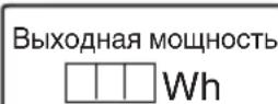
2-3-3NaHbI HOMep
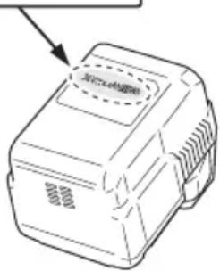
Описане НумЕРОВАньIX ПЕДMETOB (Pnc. 2 - Pnc. 46)
Ipeed c6bOpKoTprmmepa ydaJIte aKHyMylTOp.
- YctaHOBbA pyuKn-CHO6bl (Pnc. 7) (ToIbKO CG36DL (L), CG36DAL (L))
(1) YdaJInte 6oNTbI M6 x 43 (2 wT.).
(2) YcTaHOBnTe pyKy-CKO6y Ha rIaBHyTO Tpy6y HApPoTINB Kopnyca.
(3) YcTaHOBnTe KpeIeK pyuHn B HnHHeN qacTn rnaBHOn Tpy6bI n 3aHmTe erO 6oTAMn M6 × 43 (2 wT.) n raHKamn M6 (2 wT.).
ПОНМЕЧАНЕ
YcTaHOBnTe pyHy ckO6y B yIo6HOM MecTe, oBeCneuBaIOeM HaJeKHOe yIepKaHHe TpIMMepa npi pa6ote.
OCTOPOKHO
IpaBnIbHo nHaJeKHO yCTaHOBnTE pyuKy-ckOby, KaYka3aHO B INCHtpKcNIO NcNoJIb3ObaHIO.
Bcnyae HnepaBnIbHOnHnHeHaJeKHOyCTaHOBKnOHa MOKeT OTCoeDnHnTbcN nPnBeCTn K TpaBMnpoBaHNIO.
- YcTaHOBbA BeNoCnneHbIxpyJei(Pnc.8)
(1) C NOMOUIBIO 4 MM WecTnIpaHORo RaeyHoro KJIIOHa, BXOJAEERO B KOMNIEKT NOCTaBHN, ydaIInTe YeTbIpe 60JI Ta, KOtOpBle BpeMeHHO npKpEnIeHbI K pyIIO (A). 355
(2)ПрнкpenTe pyKoTkyДлправоуpyи,ИМeIoUyO pyiHaR,ИpyKoTkyДлпЯБоуpyи,a3aTeM TцaTeIbHO 3akpenTe pyIb(A)cnomoьuYeTbIpex6oIToB.
ПРИМЕЧАНЕ
3aKpeHnTe IeByIO n npaByIO pyKoTKn B NOLOKeHN, KOtOpoe o6ecneuBaET XopoWNI 3axBaT.
OCTOPOXHO
YctaHaBbBaIteJeByIO npaBvIO pyKoTKn npaBnIbHO nHaDeJxHo, KaYka3aHO BnHCTpyKcIMn O6paIeHIO.
B clyuae HnpaBnIbHoro Nnn HeHaedKHO npinkpenHeN OHa MoKeT OTBaJIITbcr N Bbi3BaTb TpaBMy.
- YdJIiHHeHne OCHOBHO Tpy6bl (Pnc. 9)
(1)OTnycnttepbHar6IOHnPOBHN,TO6bI 06eCneHTb BO3MOXHOCTb yDInHeHHOCHOBHO Tpy6bl.
(2) YdInHHe OCHOBHy Tpy6y HAcToIbKo, HAcOJIbKO 3TO BO3MOxHO, Y6eINBWHcB, YTO pa3daJcR ueJcK.
PIMMEUHNE
BnraTeIb He 6yDet pa6oTaTb, nOHa OCHOBHaa Tpy6a He 6yDet NOJIHOCTbIO yDNINHeHa.
Pn HkataH NHOHNIHTAHN KpaHaa JAMNOKA nHTaHb6ydt 6bICTPO MIRaTb KpaChbIM.
(3)Iocne ydHHeHH OCHOBHO Tpy6bI Do eJnKa, npOBepbTe, YTO6bI OTBepCTNe B yexJe DepeHaTeJIa COBnaJaIO C OTBepCTnEM B OCHOBHO Tpy6e, n 3a6loKnpyIte pbIar 6IoKupOBKn, YTO6bI HaJeHHO 3aΦHKpOBaTb OCHOBHyIO Tpy6y.
4. YctaHOBka 3aunTHoH KpbIshKn (cm.Pnc.10n11) IPEDOCTEPEKHEHNE
YCTaHOBITE3aIHTHyKpbIiKyHaMeCTO.
HecobJIOeHne 3TOro Tpe6OBAHHaMOKeI npHBecTH K TeJIeCHbIM NOBpeKdEHNAM, Bbl3BaHHbIM pa3JIeTOM o6pe3KOB.
PIMMEUAHNE
IyYCTaHOBNHCNoB3yTeWeCTnRpaHHbTOpOBBKJIIOU4MM.
(1)ДЯ yctaHOBKn HOKa B uHTOK KpbIuKn HcNoJIb3yInTe BnHT-cAMope3 D5.(Pnc.10)
(2) CoBmectnTe Dba OTBepCTnB CkO6e KpbIuKn N OTBepCTnB 3aunTHoN KpbIuKe N BCTaBBte 2 60NTa C BHyTpEHNM WeCTnIRpaHHNKOM M6 × 25. (Cko6a KpbIuKn yctHaabnBaetc Ha Kopnyce DbrarTeJ.)
(3) YcTaHOBnTe DepeKaTeIb KpbIuHn Ha HmHHIOO CTOpOHy KpbIuHn I C NOMOIbIO WecTINrpaHHOro TOpOBOrO KJIoua 4 MM NOpEpeMeHNO 3aTaNHe 2 60JTa M6 x 25 Do yNopa.
OCTOPOKHO
O Bydte ocTopoKHbI npa6oTe c HoxOM, HAXODAUMCRA NOJ KpblIKON.
O IpaBnIbHO nHaJeKHO yCTaHOBNTe KpbIuKy n HOK, KaKyKa3aHO B INHCTpyKUIN NO NcNoJIb30BaHNO.
B cIyae HnpaBnIbHOH nIN HeHaJeKHOYcTaHOBKn OHMOrT OTCoeHNHTbcra N npNBecTN KtpaBMnpoBaHIO.
5. YctahOBha peHcyuero Ie3Bn (DOnoJIHHTeJIbHbIe npHaJdJIeHHocTn) (ToIbHO CG36DL)
IPEDOCTEPEXHEHNE
O Ipepe yctahOBKo peKyueo Je3Bn8 O6ra3aTeIbHO npinkpenTe KpbIuKy Je3Bn8, HadeHbTe ToIcTbe pyKaBnCbl N BblIOJIHNTE npOue Heo6xOJIMbIe MePbI npedoctopoxHHocTn, YTO6bl ObecneHTb CO6CTBeHHyIO 6e3onacHOCTb.
O Ipepe yctahOBKo peHcyIeroJe3BnBHNMaTeIbHO npOBepbTe n y6eHTecb,TO OHO He TpeCHyIo, He DeΦopMnpoBaHo n He NMeet HnKaHX dpyrnx NOBpeXDeHn.
O Pn yctahOBKe peKyuJero Je3BnA ChaAna npKpeNITE KpbIshky peKyuJero Je3BnA, 3akpeNIB OTBepCTne B cepDInHe peKyuJero Je3BnC BbICTynom fHaHcEBoB c6OpKn, TaK, TTo6bl peKyuJee Je3BnB BXoHnIO B KpbIshky raIKN, a ceHTpaJIbHna JaCTb peKyuJero Je3BnH He npocKaJIb3bIbAlo. (CM.Pnc.21)
Pycchn
O NocIe yctaHOBKn peKHyUeeroJe3BnHe 3a6yDbTe y6paTb WeCTnyrOJbHbI raeuHbI KJIouH n TOpOBoi IraeHbIKIOU.
EcIn Ha IeBOcTOPOHHe yCTaHOBOUHOr rAIKe M10 nIN KpbIuKE raIKN BnDhBi CJIeDbI N3HOca INN HCTnpAHn, 3aMeHNTe Ha HOByO yCTaHOBOUHy OraKy INN KpbIuKy RaIKN.
(1) BctaBte ΦlaHueByo C6OpKy B Kopnyc DBnraTeJy. B 3TO Bpem KpbIIO φlaHueBOB C6OpKn DoJIHKHO 6bITb 6paueHO B CTopoHy Kopnyca DBnraTeJy. (Pnc. 18)
(2) yCTaHOBKn peKHyIeOJe3BnB, BCTaBbTe npInlaeraembi WeCTnIpaHHbT OTOOBH KIOUy B OTBepCTNaHaΦJaanCeBOBc6OpKe H Kopnyce DBNrTaTeN I NO OuepeNi pRkpenTE peKHyIee Je3Bne N KpbIuKy raikn. (Pnc. 19)
YcTaHOBnTe peKyuuee Ie3Bne, NOBOpaHbA erO B HApPaBHeHm, Yka3aHHOM cTpeJkoI.
PIMMEUAHNE
Nocne HaJeXHoro 3aKpyuBaHnO Otperyu npTe TaKIM o6pa3OM, YTO6bl IeBOcTOpOHIO yCTaHOBOUYo raHy M10 MoxHO 6bIIO 3aKpyuBaTb NOTKpyuBaTb. Ecn 3To He cdeLaTb, Bo3MOHHa DeΦopMaunr PhaHceBoi C6OpKn HnO Tka3 DeΦJIeKTopa.
(3) PacnoIIOKHTe 3aKpyrIeHHyIO CTOPOHy IeBOcTOPOHHeY cTaHOBOuHOI raiKn M10 TaH, YTO6bI OHa 6blna 6paueHa K TopceBOMy raeHOMy KInOhy, a 3aTeM HadeJHKHO 3aKpyTHe. (Pnc.20)
(4)ПоберьтейубиТecь,чTo peHyцeeлзВе yctaHOHnHaJIeKaUIMO6pa3OM.(Pnc.21)
6. Hpenlenne nIeBoropemn
IcnoB3yIe TB KOM6nHaunC 6aTapee BSL3620.
PNEOCTEPEKHEHNE
OДЯ npaBnIbHoi pa6oTbI c TpHMpeMOp Heo6xOHNMO 3aKpeNITb IJIeYeBOI peMeHb.
Ecn TpMMep He pa6oTaet HopMaIbHo, HEmeJeHBO BbIKIOHTe DBnraTeIb, pacCTeHNTE CKOby-3aUeKpy pEMHry n CHMITE TpMMep.
OCTOPOKHO
Ecn He 3aKpeNtB TpMMep NleHeBbIM peMHem, OH MOKeT yNaCTb IN NOBpeNTbcr Pn NaDeHm H/IN npuHHntb TpaBMy. DePKHTe rAABHyTOpy6y OndHO pyKoN TAHNTe 3a fHKcTop dpyro pyKoN.
O Ipeed hauaIOM pa6oTbI y6eHITecb, YTO 6bICTpopa3bemHa3aueJka pa6oTaET HopMaJIbHO.
(1)HaeneHbTe pemeHb Ha nIeO, KaK nOKa3aHO Ha Pnc. 12 (nIy IcNoJIb3OBAHnra 3a npedeJaMn EbpOnbl CM.Pnc.14) INoDBecbTe Ha Hero TpMMep. OtperyLnpyIte dINHy nIeYeBOrO peMHr.
(2) OTOOeHHeHr TpMMepa OT IJIeueBOrpoemH, BO3bMHTe 3a rIaBHyTOpy6y, YTO6bI ppeOxpaHHTb TpMMepOT NaEHHa, a Dpyroyn pyKoN OTCTERHnTe peMeHbOT CkO6bI, KaN NOKa3aHO Ha Pnc.12 (JIN HcNOJIb3OBAHn 3a IpeDeJaMn EbpOnbl cm.Pnc.14).
(3)ДлгпсоeннehнТрммepaКрemHbBCTaBBTe CkOby B KpOCH N BCTaBBte 6bICTpopa3bEmHyTO CkOby Hd KpOChKOM B WnPOKoe OTBepCTne KPOHwTeHa. (Pnc.13) (ДлгИСПОЛБ3OBAHN3aInpedIaMn EBponblcM.Pnc.15) CJIerkaNotTaNHTe 3apeMeHb,уTObIy6eINITbcra,чTO OH 3aKpePnIeH npabInbHo.
7. YctahOBKa NOBBeCHOro pemHr
IcnoB3yTe B KOM6nHaunC 6aTaapeeBL36200.
IPEDOCTEPEXHEH
O63aTeIbHO npKpeNte NOBecHO peMeH TaH, YTO6bI TpMMep MOHb 6bIIO npaBnIbHO nepeHocHTb.
EcnBbIyBCTByeTe,HTO INHCTpyMeHT He pa6oTaET HopMaJIbHO, HEmdJIeHHO BbIKIOHNTe DBnraTeJIb, HaKMITE BBICBO60JdaIOUIM MExaHn3M NOdBecCHOPOemHn CHMlTE INHCTpyMeHT.
OCTOPOXHO
EcIn BbI He NoJdepeKnBaete HNCTpyMeH Tnp HaKaTIN BbICBO6OxJaIOUeTo MExaHN3Ma, OH MoKeT yNaCTb, BbI3BaB TpaBMy INI NOBpeKdEHe.
DepKHTe OCHOBHyIO Tpy6y OJHOI pyKO, HAnHMaI pyrO pyKO.
O Ipeep Haayanom pa6oTb y6eHntecb, YTO fynKnBbICBO60KDeHn HOpMaJbHo fynKcNoHpyeT.
(1)Пицentе noBecHоpeMeHbK cTpone BL36200 (В дByx MecTax),Кан nOKa3aHoHa Pnc.16. 3aTeM npiCenTE peMeHb K NOBcHe OCHOBHOr Tpy6bl (B OdHOM MeCTe).OTperyIInPyIte noBecHoipeMeHbdo HxHOnДINHbI.
(2)ДлгOTcoeHHeHnIHCTpyMeHTa OT NOBecHOPOemH,уDEPKBaIte OCHOBHyTOpy6y OndHpyKoNHaKHMaITe BbICBO6OxHaIOUm MExaHn3M NOBecHOPOemHcO6eHX CTOpOH,KaK NOKa3aHO Ha Pnc.17.
IpynKpeHEnH INHCTpyMeHTa BCTaBJIte BH3y, y6eINBWHCB b npabNbHOCTn npKpeHEnH.
TOJIOBHA C HENJOHOBOICTPYH0I
YCTAHOBKa NOJyABTomATnueCHOI ROJOBHn C HeJIOHOBOI CTpyHO IHCTpyMeHTa
1.Функин
OcyuEcTBnEaBtOMaTneChyIONoaCyHeHIOHOBOI CTpyhbl npn cnaob ydape 0 3emnlo.
TexHHuechne xapaHTepnCTHKn
BbIaHHTe CtpHy Ha Heo6xOmyo DInHy.
4 3aMeHa HeIIOHOBoCtpyHbI
(1) PocroToBbTe 4 M opunHaJIbHoi HeIIOHOBo HHTn Ha Puc.22.(KoI n3JeINr No 335235).
(2)HaKMnte pacnoJIOKeHHbIe Ha npOTnBOJIOJHXbIX KOHcax 3aueJIKN I CHMNTe KpbIuHy c Kopnyca. (Pnc. 26)
(3) YdaJIInTe KaTuShy H3 KOpnyCa. (Pnc. 27)
Ecn HeNoHOB a CtpyHa eue ocTaNacb, 3aennte ee B Bblkax, a 3aTeM ydaJIte KaTyUky.
Ecn HeNoHOBc TpyHa (KoN3eNn N 335235) He BbITrNBaETC, XOTy ee OCTaIOcB eue IOCTaTOUHO, IIN BO Bpem ee 3ameHb CMotaTe CtpHy CJeDyUOuIM O6pa3OM.
(4) OctaBbTe npMepHo 150 MM HeJIoHOBOO shHypa c Obox KOHcOB, CIOXHTe CpeHIOU qACTb IN pNKePENTE K KpOky Ha 6o6nHe. 3aTem IpODeHbTe uHyp B 6o6Hy B HappaBLeHH, NOKa3aHHOM CTpeIKN, CJIeJ 3a TEM, YTO6bl OH He NepeKpeuBaIcR (Pnc.28,29).
(5)OctaBbTe HecMOtaHHbIMn npHmepHo 100 - 150 MM HeJIIOHOBOI cTpyHbI, 3aueHNTe n 3aΦHKcHpyIte ee B ΦHKcaTope. (Pnc. 30)
ПОНМЕЧАНЕ
He daBaIte HeJIOHOBO CTpyHe CnyTaTbCBO BVPeM 3aKpeJIeHnE ee BФHKCaTope.(Pnc.31)
(6) CoBmecTHTe NOIOXHeHne ΦHkCaTopa HnPaBIAHOUeI CTpyHbIC OTBepCTHEm, 3aTeM BCTaBbTe KhoNky B Kopnyc.
Ocb6oBnte ctpHy n3 fKcaTopa, cIerHa npnepxNBa KaTyuKy, 3aTe M yloHnTe ee B HanpaBnIOyUcTpyHb C OTBepCTHeM. (Pnc. 32)
(7)HaKMMTe 3aUeJIKNHTe 3aUeJIKN KOpnyca BΦHKCnpyUOxN OTBepCTnX KpbIuHKn. (Pnc. 33)
PNEDOCTEPEKHEHNE
Y6eIInTeCb, YTO 3aueJIKN NIOTHO 3aΦHKCnPOBaHbIB ΦHKcnpyUoX OTBepCTnX.
IcnoB3OBAHne yCtpoiCTBa 6e3 HdJIeHauei
fHKcauN 3JIeMeHTOB MOKeT PnPBecTN K
TpaBMnPOBaHIO OTJeTaIOUIMM DeTaJAMN.
(8)HaTaNHTe cTpyHy, 3aTeM o6peXbTe ee HOHNUaMN, OCTaBnB OTe30K 90-110 MM. (Pnc. 34)
3KcPJIyATAU
CTpHHKa TpaBbl
PPEOCTEPEXEHNE
O 3anpeaetc3Kcnnyataunr Tpmmepa Houbno nnB yCIOBnX IIOXoN BNDMOCTn.
O 3anpeaetcpa6oTaTb c Tpmmepom BO BpeMdoJnI npca3y nocJe doJd.
OДЯ npeDoTbpaueHn O T NaeHn BcIeCTBne NOTePn paBHOBecn Ha cKoJIb3KOM rpyHTe HaDeBaN Te NOxOJyUO6yBb.
O 3anpeaetcpa6oTa c TpHMMepom Ha KpyTbIX CKIOHax.
Pn CTpnKHe TpaBbHa CCHIOHAX yMepeHHOn KpyTN3Hbl,
DnRaITeCb No HApBaJIeHNIO BBepx.
O IonoHnTe npaByo pyHy Ha pyKoTky, a JeByo - HpyKy-cNo6y. KpeNko DeepHnTe TpMMep.
He noHocHTe rOIOBHy c HeJIOHOBOI CTpyHOI CnIHKOM 6JIH3KO K HORAM.
O Ppi pa6oTe He IIOHMaTe rIoBky C HeIIOHOBOI CTpyHOBbIe KOJIeHa.
3anpeaetcHcnoJb3oBaTb TpMMep B MecTax, rDe roJIOBka C HeJIOHOBOI CTpyHOH MOKeT BCTyNTb B KOHTaHT C KAMHAMN, DepeBbAMN HIN DpyHMN NOCTOpOHHMN PpeDMeTaMn.
O Pn BpaueHn rOIOBn C HeIIOHOB cTpyHO NocJe OTHIOUeHn DBNrAteN OHa MOKeT pNHyHnTb TpaMbI. EcIn yCTPOJCTBO OTHIOUeHO, y6eINTeCb, YTO rOIOBKa C HeIIOHOB cTpyHO OCTaHOBUNAcB, IpeKHeYEM CHrTB yCTPOJCTBO C pEmHra.
O 3aPpeaaeTcpa6oTa c TpHMMepom 6nHe 15 M ot IIOJe. Pn pa6oTe B nape, co6IIOaJTe pacCToHne B 15 M.
O EcIn Bpaauoueecra Je3BnI npuTy B COpnKOCHOBEHne C TBepbIMN 06beKTamn B KpHTnueckOn 30He, BO3MOxHO BO3HnKHOBEHne ynpa Jle3BnI.
MoJcET BO3HnKHyTb CHTyaun, HecyuaonacHOCTbIa onepatopu n o6OpUdoBaHna. 3TO RAJIeHne NOLyHIO Ha3BaHHe ynp JezBn. B pezylbTaTe onepatop MoKeT NOpePbTb YnpaBHeHne yCTpOInCTBOM, YTO MOKeT npINBeCTN K cepBe3HbIM I DaKe φaTalbHbIM TeJIeCHbIM IOBpeJeHnM. Ynp JezBnEM MOKeT pOn3oITN B MecTx C PLOXO BNIMOCtBu.
- BctaBbTe B TpHMMep aHHyMyIaTOp, co6IIOda nOJIaPHOCTb.
2. Bhlochnte Tpmmep (Pnc. 35)
HaHMMte KhoNky BkIIOUeHnna NtAHnHa KOpnyce yCTpOyCTBa. NtAHnE 6yDet BkIIOUeHO n Ha pyKoRrTe 3aROPNTc KpaCHa CnHaJIbHaJaAMNoOka NtAHn.
O NobTOpHo HaKMnTe KHOHky BKNIOUeHn NITaHnHa KOpNyCe yCTpOInCTBa. NITaHne 6yDet BbIKIOUeHO n KpaCHa CnHaJIbHn JaMIOuKa NITaHn Ha pyKoTKe NorachET.
[ABTomatHueechoBbIKIOUHeHne]
Ecn, nocne BkIOUeHn IITaHn He HaKaTb HapbIar B TeueHne 1 MHyTbI, TpMMep ABTOMaTHeCNBbIKIOHTc. IIN NOBTOPHO BkIOUeHn TpMMepaHaKMNTe KHOINy BkIOUeHn IITaHn ONrTb.
IPEDOCTEPEXEHNE
He octabnIte Tpmmep 6e3 npncmOTpa BO BHKIOHcHOM COCTOHN! 3TO MOKET pINBecTN K HeccaCTHOMy Cnyaio.
3. Pa6oTa pbIyara n TopMo3 (Pnc. 36)
YTo6bl 3aynctnB BpaueHne peKyuIero Je3Bn npn BHJIOeHHOM IINTaHHN, NOTARHITe pbIyar, HaxHMaR pbIur 6bLOKInPOBKn.
EcnBbO TnpyCTHe pbIar,TopMO3 npIeT B DeIeCTBHe Ha 1-3 ceKyHdbI,ocTaHaBnBaB aBpaueHne peKyuIero Je3BnA.
Ipeed nCnoJb3ObaHem HnCTpyMeHTa y6eINTecb, TTO Topm03 pa6oTaet HopMaJIbHo.
4.Дисн chopостeн(Pnc.37)
Ha Kopnyce NMeETcN DnCK CCHOPoCTe DnIyI3MeHEnn CHOPoCTu BpaUeHN B DnAna3OHe5800-7000 MNH-1. NOBOpaUNBaIte DnCK NO YacOBOn CTpeJIke DnI yBVeJIuYeHn CHOPoCTu IN pPOTNB YacOBOn CTpeJIKN DnI yMeHbUeHN CHOPoCTu.
5.CtpnHHa TpaBbI
O 3axBaTnTe pyKoTky Cbepx, HaKMnTe pbHar 6IOKnPOBKn I NOTHNe pbHar, YTO6bl 3aNyCTnTB BpaueHHe peKuIe RoJOBKn. (Pnc. 38)
O Nocle OKOHuaHnCTpNnKn TpaBbI OTnyCTnTe pbiHaR N BbiJIIOHTe DnRaTeNb.
O TomecHTe 60JIbwoI naiueHa pyKoTky N oxbaTHTe pyKoTky dpyrHmN naIbuaMn. (Pnc. 39) (ToIbko CG36DL, CG36DAL)
O OxbaTHe KnCTbIpyKn pyHy-CHO6y TaK, TTo6bI 60JIbIoI naneu HaxoDIncra CBepx.y. (Pnc.40) (ToIbKO CG36DL (L), CG36DAL (L))
O PnIMTe yo6Hyo n03y, KOtopa no3BOJareT IerKo DBrTaTbca.
[MeToaKa CTpHHN TpaBbl]
He kaayte Tpy6y. Nobopauhba 6eipa, nepemueaTe peKyuTo roIOBky B rOpH3OHTaIbHO NIOCKOCTn Cnpaba HaneBO NO dyre, npN 3TOM MeJeHNO DBVaRcB BnepeJ. Dnype3Kn TpaBbl NCNoIb3yIne Te IeByIO CTOpOHy roIOBHN C HeJIIOHOB ONCTpyHO.(Pnc.41)
MEPbI INPEIOCTOPOXHOCTN IPN PABOTE
Дительная pa6oTa
Tpmmep cna6ken Tepmopele, KOtOpoe npedotBpaaet nepereb 3neKtpOnHbix y3IOB, ynpablaHOx x aKHyMylTOpOM. Pn dIITeBHO pa6oTe TempepaTypa Tpmmepa BO3pactaET, uCTPONCBO 3auNTbI OT nepereBa MoKet cpaTaBtB, BbIKluOa DAIBrAteIb.
EcnI 3TO npOn3oUNo, Heo6xOJMo npeKpaTnB pa60Ty I DaTb yCTpOInCTBy OXlaDNTbc. NocJe TOrO, KaK TEMNepaTypa CHN3HTcR, MOHNO BO3o6HOBnTB pa60Ty C TpIMMepom. B clyae BO3HNKHOBEHnR Heo6xOJMOcTN B 3ameHe aKKyMyIATopa PnnpoDOJIHKTeNbHn PA60Te TpIMMepa, BblIOHOTe erO n OCTaBBte B BblIOHueHHOM COCTOHN pImMePHo Ha 15 MNHT.
3aunTa oT neperpy3KN
B daHhoe yctpoiCTBO BcTpoeHa cxema 3aunTbI OT neperpy3KN 3neKTPoHHbIX DeTaeN CnCTEmbl ynpabLeHn. Pn DInTeJbHOH neperpy3Ke BO BpeM NOpde3AHN (6bOKnPOBbHa HeJIIOHOBO CTpyHbI N T.n.) cpa6aTbIBaET CXema 3aunTbI OT neperpy3Kn, OTKIIIOUOJAA JBNrAteJIb. Ecn 3TO npOn3OJDeT, OTHJIOHTe NITaHHe yCTpoiCTBa, a 3aTEM yCTpaHNTe npuHHy neperpy3Kn.
Ecni nocle octaHOBa DnIraTeJIHaKaTb pbIyar, 6ydet MIRATb IaMNoUka NITAHNc (cm. cTp. 354, "O JAMNOUHE NITAHNc"). EcIn IaMNoUka NITAHNc 6ydet MIRATb 6oJIe 5 ceKHyd, NODaYa NITAHNc ABTomatUcheKn BbIKJIOuHTcR. EcIn 3TO npOn3OJeT, ycTaHNTe PpUHy Nepepy3Hu, a 3aTEM CHOBA HaKMITE KHOHky BkIIIOueHry NITAHNc, YTO6bl IpOdoJIHNb paBoTy C yCTPOINCTBOM.
IpehenocHa HnctpyMeHTa (Pnc. 42)
OCTOPOXHO
O YdaJInte aKHyMylTOpHyo 6aTapeo n HcNoIb3yIte KpbIshky peHcyuero Ie3BnI dIra 3aunIbIpeHcyuero Ie3BnI pni nepeHOcKe IHCTpyMeHTa.
Pn npehocke HnctpymEnTa 6e3 npedbapntelbHOn yCTaHOBn Ha MeCTo KpbIuKn peKyuIero Je3BnJ Ie3BnE HaxoDHTcR HeNOCpeDCTBeHHO pAOM C TeIOM, YTO MOKeT PnNBecT N TpaBMe.
O NpehenocHTe HNCTpyMeH, ydePKNBaI erO pyKaMn HnnpaBnB peKyuEe Je3BnB B CTOPOHy OT Ta.
O PtB TBAHIN OCHBOH Tpy6bI 6yDbTe OCTopoHHbIC 3aocTppeHHbIM KOHcOM Hne npuicMeTte naJIbci. (ToIbKO CG36DAL, CG36DAL (L))
Otnyctnte pbyar 6loKnpOBHn IN BTHNTE OCHOBHyIO Tpy6y. 3a6loKnpyIte pbyar 6loKnpOBHn, noka BbICTyn He ydapNTc06 OCHOBHyIO Tpy6y. DaHHa npoceDypa N03BOJAreYMeHbWHTb IHCTpymENT DO KOMNaKTHorO pa3Mepa.
OchOBHnA Tpy6a MoKeT BtRnBaTbC B JIO6OM NIOJKeHN. BbI6epnte nOxOJaUy O DnHy dNpeHoCCH N XpaHeHN. (ToIbKO CG36DAL, CG36DAL (L))
TEXHnueCHOE O6CJIyJHHBAHNE N OCMOTP
OCTOPOKHO
IpeepHaayamOcMToPa TpMMepa HINTexHnueCkOro 06cLyHbAHnH N3BLeHnTe aHHyMyJrTOp.
1. Поберka coctoHn rOIOBn c HeJIOHOBOI CTpyHOH.
Heo6xOIMOpeyIpaHO npOBnTb npOBepKycOCTOHHra
roBnC HeIIOHOBOc TpyHO. PpN CnHbOM N3HOce
HIN IIOLOMe rOIOBKn OHa MOKeT PPOKaJIb3bIBaTb,
PON3BOIDTeJIbHOCTb DBNaTeJIa 3HaYNTeJIbHO
CHINKaETCn IN DBrAteJIb MOKeT BByTIuN3CTPOJ.
B TaKOM Cnyuae Heo6xOdHMO yCTaHOBnTb HOByIO rOIOBHN C HEnJIOHOBOI CTpyHOI.
OCTOPOXHO
PpIMHeHnepeKyuIeRTOIOBcCnJIbHbIMN3HOCOM HINPOLOMKOONaCHO!3aMeHInTeROIOBkyHaHOByIO.
2.ПоверпгБИNTbl
EcnBnHTbHe 3aKaTbI,3TO Co3daeT onaChbIe ycIOBna.PeryJrpho npOBepRnTe BNHTbl. OHn doJIHHbIb6bITb 3aKaTbI.
OCTOPOXHO
IpImeHHeN TpIMMepa C BbIBHHYeHHbIMN BNHTAMN InpdctabJRE6oJIbSyIOOnaCHOCTb!
3. OcmToP yroIbHbIX ΜeToH (Pnc. 43)
B Dbratene HcnoJb3yIOTc yrolbHbIe 8ETK, KOtOpbe NoCTeEHNO 3HaunBaIOTc. TaK KaK Ype3MepHO N3HOweHHaYrOJIbHbA 8ETKa MoKeT PnPBecTH K HeNCpabHocTN DBratEn, 3aMeHnTe N3HOweHHbIe yOrlbHbIE 8ETKN HObIMN, KOrDa OHN DOCTHRHT COCTORHN, 6nN3KOrO K "PpeJeN u3HoCA". KpOME TOrO, Bcerda CoepKInTe yrolbHbIe 8ETKN B uHCTOTe I O6raTeJIbHO CLeIInTe 3a TeM, YTObI OHN MOJI N CBO6oHDHO CKoJIb3NTB B 8ETKOdepHataJIax.
PIMMEUAHNE
Pn 3ame He yrolbHOn uetKHO HOB OYrolbHOn uetKo HOBa3eJIbHO NcNoJIb3yIte yrolbHyO uetKu HInpMb1 Hitachi, KOD No 999015.
4. 3aMeHa yroIbHbIX uTeTOK
BbHbTe yroIbHyIO uTeKy, CnR B ChaHaJa KpbIuKy uTeTKN, a 3aTEM 3aueINB BbICTyNaUOyU YoACTb yroIbHOJ uTeKNI npN NOMOUI OTBePTHN C NIOCHM Je3BHeM N T.I., KaK NOKa3aHO Ha Puc.44.
Pn yCTaHOBe yroJIbHOJ uETKn BbICTyn Ha uETKe DOJIHHe cOpnHaCaTbcra C KOHTaKTHOJ NOBepxHOCTbIO rHe3da nIy uETKn (cM.Pnc.45).BCTaBBte uETky B rHe3do, KaK NOKa3aHO Ha Pnc.46. NocIe 3TOrO yCTaHOBNTe KOJINaOH uETKn.
OCTOPOXHO
A6COJIOTHO TOHNO y6eI NTecb B TOM, YTO BCTaBNI NODpyKHeHHbIK KOHTAKYROlbHOUeTKB UyactOK KOHTAKTa CHAPyKN UeToOHrNl3bl. (Bbl MOKeTe BCTaBNTb IIO60oOHNn 13 DByX PpeDyCMOTpeHHbIX NOIDpyKHeHHbIX KOHTAKOB.)
O Heo6xOdHMO co6nIOaTb ocToPOXHOCTb, nocKOBky IIO6a OwN6Ka npBbIOJHHeHN 3ToI ONepaUN MOKeT npNBecTN K DeOpMaUIN NODpyKHeHHORo KOtAKTa yroJbHOI UeTKN H CTaTB npuHHOI NOBpeHDeHN DBNrTaTeHa paHHe CTaDN.
5. HapyKHa OunchTa
Korda ydaphbl wypynOBep 3arp3nTcBbITpe ero mRkO cyxO TkaHbIO nIN TkaHbIO, CMOeHHoMblbHO BOD. He nCNoIb3yIne pactBOpNTeJn, coDeprKaUne Xlop, 6eH3nH nIN pactBOpNTeJb DJIkpackN, TaK KaON MOrTy pactBOpNTb NlaCTMaCCy.
6. XpaheHne
XpaHnte ydapHbI WypynOBepT B MecTe, HeIOCTyINHom DeTAM, n npn TemnepaType He Bbiue 40^
ПРИМЕЧАНЕ
XpaHeHne NOHHo-JIHTneBbIX 6aTapei
Y6eNTecb, YTO HONHO-NTNtneBbIe 6aTapeu NOLHOCTbIO 3apJKeHbI nepeD TeM, KaK y6paTb Nx Ha XpaHeHne.
XpaHHe 6aTapeB TeeHne IInTeIbHorO npomEHyTKa BpeMeHN (3 Mecau nn 6oJeep) npn HN3KOM ypoBHe 3apraMoKeT npNBecTH K yxUdHEnIO XapaKTepNCHK, 3HaHTeJIbHOMy COKpaueHENIO BpeMeHN ICNoJIb3OBaHnR 6aTapeN, a TaKHe MoKeT CTaTb HeBO3MOJHnA nepe3aprJa.
OHaKo 3HaHTeJIbHO yMeHbUWBueecBpeMnCNoJIb3OBaHH6BaTApEN MOKeT 6bITb BOCCTaHOBJIeHO npNIOBTOpHO 3apJKe NcNoJIb3OBaHH6BaTapeN OT DByx Do nIpa3.
EcnBpemnncnoIb3oBaHn6bTapeu qpe3blyaHo Hn3Koe HeCMOTpr Ha NOBTOPhyIO 3apAky n IcNoJIb3oBaHne, cpoK cnYk6bl 6bTapeu nCTeK, npno6peTHTe HOBbie 6bTapeu.
OCTOPOKHO
Pn HcnoJb3ObaHnn nn Texo6ClyKHBaHHn HNCTpyMeHTa Bcerda CNeIte 3a BblNOJIHeHEm BCex npabNI HOpM 6e3OnaCHOCTn.
BbIbOP PnHaJLeJXHOCTeI
Cnncok npHaJTeKHoCTe DaHHoMaHbI yKa3aH Ha cTpaHnce 362.
Baxnna HhOpMaun O 6aTapex JI86cnpoBOdHbIX 3JeKTPoHnCTpyMeHTOB Hitachi
Bcerda nCnoJb3yIte fHpMeHHbIe 6aTapeu, npedHa3NaueHHbIe NmEHNO DIAHHO INHCTpyMeHTa. Mbl He rapaHTnpyem 6e30nacHOCTb I yHKnIOHnPOBaHne HaNX 3JeKTPoHNCTpyMeHTOB pN HCNoJIb3OBAHIN 6aTapeu, hroTOBLeEHbIX He HauWe KOMnAHNeI, IIN JHe pa3o6paHHbIX N MoDnΦnUPOBaHHbIX 6aTapeu (B KOtOpbIX 6blI dEmOHtnPOBaHbl I 3aMeHebl RaJIbBAHnYeCHNE 3JIeMeHTbl 6aTapeu NN dpYrIe BHyTpEHHne DeTaII).
HEIOLADKIN CNOCOB INX YCTPAHEHNA
PnB O3HKnHOBeHn HenoIaOK npa6Ote TpMMepa Nolb3yTeCb CneDyHoue Ta6JIuee: Ecln, Nolb3yRcTa6JIuee, ycTpaHnITb HenoIaIKy He ydaIOcb, 6oPaTntEcB B aBTOpN3OBaHHb CEpBHCbY ceHTp KOMpaHIn Hitachi.
| Призник | Возможнaya priчниа | Способ устраенья | |
| Зарадhoe uстюстvo | Ламочka зардноу uстюства не горот. | Сөтевий shнур зардноу устюства не влкючень сөть. | ВлкючITE сөтевий shнур зардноу устюства сөть. |
| Нэр本场比赛 установа.akкумлajtorpa в зардноу устюстvo. | Встыte akкумлajtorb в зардноe устюствВ COOTBETCTBи C указаняМи HabToяцeroPykoBoDCTBa. | ||
| Заграденье заektpruchесни контактOB akкумлajtorpa пли зардноу устюства. | ПронзveдITE чicitКУ SFLEKTPRuchesKING KONTAKTOB BAtHBIM tamnoHOM. | ||
| Аккумлajtorс silentlyногHarpeBaetcra. | Перед зардковだайе akкумлajtorpyполноctью OCTыITb. | ||
| Инсттумент | Тримmedер не paботаet. | Аккумлajtorр разroduлься. | ЗагдITE akкумлajtorp. |
| Аккумлajtorр установ lien He npabvihlo. | Из玮ение akкумлajtorр иЗ akкумлajtorphoro OTCSEК Триммера и правьтЕ, HeT ЛВ akкумлajtorpHOM OTCSEК NOCTOPOHNIX Праздmetob.Tаюне правьтЕ akкумлajtorр на праздmetOTCYTCTBи Заграденье КонтактOB, ПonaДаняВODы пли дугин NOCTOPOHNIX Праздmetob.Длэчstkn ПОлььзчteь BaTHbIM tamnoHOM.При установке akкумлajtorpa в akкумлajtorрьн的眼OTSEK НжмITE на Hero до щeчka. | ||
| Питанные Тримmedera не влкючateя. | Для Внлоченя Тримmedera нажмite КногнуВнлоченя Питаняна Корпуне. ТримmedсабжениФунksей abTomatчесногВнлочenя.TримmedaВTomatчеснВнлочаeTCR, сelenВ точениODно МИнTuВпLoСе Внлоченя He нажат纳pblyhar.Для ПОВТOPHOrO Внлоченя ТримmedaНжмITE КногнуВнлоченя ПITANЯ ONЯТь.Dдя Вьнлоченя Тримmedera нажмite КногнуВнлочenя ПITANЯ оse pa3. | ||
| Признak Возь можная р以习近平 Способ устраеня | |||
| Исторгопment | Триммер не павOTаe. | Освовская труba не палною витяна (БыICTpoe магане Кра当然是) (Толък CG36DAL, CG36DAL (L)) | |
| При поемецни рынaria заимны рычаг не пол нахот. | |||
| Триммер заимец с来不及停下来. Триммер заимец с来不及停下来. Триммер заимец с来不及停下来. Тримm器 заимец с来不及停下来. Тримm器 заимец с来不及停下来. Тримm器 заимец с来不及停下来. Тримm器 заимец с来不及停下来. Тримm器 заимiec с来不及停下来. Тримm器 заимiec с来不及停下来. Тримm器 заимiec с来不及停下来. Тримm器 заимiec с来不及停下来. Тримm器 заимiec с来不及停下来. Тримm器 заимiec с来不及停下来. Тримm器 заимiec с来不及停下来. Тримm器 заимiec с来不及停下来. Тримm器 заимiec с来不及停下来. | |||
| Триммер заимец с来不及停下来. Тримm器 заимiec с来不及停下来. Тримm器 заимiec с来不及停下来. Тримm器 заимiec с来不及停下来. Тримm器 заимiec с来不及停下来. Тримm器 заимiec с来不及停下来. Тримm器 заимiec с来不及停下来. Тримm器 заимiec с来不及停下来. Тримm器 заимiec c Тримm器 заимiec c Тримm器 заимiec c Тримm器 заимiec c Тримm器 заимiec c Тримm器 заимiec c Тримm器 заимiec c Тримm器 заимiec c Тримm器 заимiec c Тримm器 заимiec c Тримm器 заимiec c | |||
| Триммер востановская рычаг. | Небостаочны зард akнунл�ота. | ||
| Преррев поимец. Спостаочны длины. Освовский трува BO Враимя. Рав�ы. (БыICTpoe магане Кра当然是) (ТOLък CG36DAL, CG36DAL (L)) | |||
| Спльна востановская рычаг. | Небостаочны установская рычаг. Спостаочны установская рычаг. Спostаочны установская рычаг. Спostаочны установская рычаг. Спostаочны установская рычаг. Спostаочны установская рычаг. Спostаочны установская рычаг. Спostаочны установская рычаг. Спostаочны uralan. Спostаочны uralan. Спostаочны uralan. Спostаочны uralan. Спostаочны uralan. Спostаочны uralan. Спostаочны uralan. Спostаочны uralan. Спostаочны uralan. Спostаочны uralan. Спostаочны uralAN. Спostаочны uralAN. Спostаочны uralAN. Спostаочны uralAN. Спostаочны uralAN. Спostаочны uralAN. Спostаочны uralAN. Спostаочны uralAN. Спostаочны uralAN. Спostаочны uralAN. Спostаочны uralAn. Спostаочны uralAN. Спostаочны uralAN. Спostаочны uralAN. Спostаочны uralAN. Спostаочны uralAN. Спostаочны uralAN. Спostаочны uralAN. Спostаочны uralAN. Спostаочны uralAN. Спostаочны uralIAN. Спostаочны uralAN. Спostаочны uralAN. Спostаочны uralAN. Спostаочны uralAN. Спostаочны uralAN. Спostаочны uralAN. Спostаочны uralAN. Спostаочны uralAN. Спostаочны uralAN. Спostаочны uralANS. Спostаочны uralAN. Спostаочны uralAN. Спostаочны uralAN. Спostаочны uralAN. Спostаочны uralAN. Спostаочны uralAN. Спostаочны uralAN. Спostаочны uralAN. Спostаочны uralAN. Спostаочны uralANO. Спostаочны uralAN. Спostаочны uralAN. Спostаочны uralAN. Спostаочны uralAN. Спostаочны uralAN. Спostаочны uralAN. Спostаочны uralAN. Спostаочны uralAN. Спostаочны uralAN. Спostаочны uralSAN. Спostаочны uralAN. Спostаочны uralAN. Спostаочны uralAN. Спostаочны uralAN. Спostаочны uralAN. Спostаочны uralAN. Спostаочны uralAN. Спostаочны uralAN. Спostаочны uralAN. Спostаочны uralTRAN. Спostаочны uralAN. Спostаочны uralAN. Спostаочны uralAN. Спostаочны uralAN. Спostаочны uralAN. Спostаочны uralAN. Спostаочны uralAN. Спostаочны uralAN. Спostаочны uralAN. Спostаочны ural_AN. Спostаочны uralAN. Спostаочны uralAN. Спostаочны uralAN. Спostаочны uralAN. Спostаочны uralAN. Спostаочны uralAN. Спostаочны uralAN. Спostаочны uralAN. Спostаочны uralAN. Спostаочны uralANI. Спostаочны uralAN. Спostаочны uralAN. Спostаочны uralAN. Спostаочны uralAN. Спostаочны uralAN. Спostаочны uralAN. Спostаочны uralAN. Спostаочны uralAN. Спostаочны uralAN. Спostаочны uralAS. Спostаочны uralAN. Спostаочны uralAN. Спostаочны uralAN. Спostаочны uralAN. Спostаочны uralAN. Спostаочны uralAN. Спostаочны uralAN. Спostаочны uralAN. Спostаочны uralAN. Спostаочны uralA. Спostаочны uralAN. Спostаочны uralAN. Спostаочны uralAN. Спostаочны uralAN. Спostаочны uralAN. Спostаочны uralAN. Спostаочны uralAN. Спostаочны uralAN. Спostаочны uralAN. Спostаочны ural安. Спostаочны uralAN. Спostаочны uralAN. Спostаочны uralAN. Спostаочны uralAN. Спostаочны uralAN. Спostаочны uralAN. Спostаочны uralAN. Спostаочны uralAN. Спostаочны uralAN. Спostаочны uralAM. Спostаочны uralAN. Спostаочны uralAN. Спostаочны uralAN. Спostаочны uralAN. Спostаочны uralAN. Спostаочны uralAN. Спostаочны uralAN. Спostаочны uralAN. Спostаочны uralAN. Спostаочны uralMAN. Спostаочны uralAN. Спostаочны uralAN. Спostаочны uralAN. Спostаочны uralAN. Спostаочны uralAN. Спostаочны uralAN. Спostаочны uralAN. Спostаочны uralAN. Спostаочны uralAN. Спostаочны uralAB Спostаочны uralAN. Спostаочны uralAN. Спostаочны uralAN. Спostаочны uralAN. Спostаочны uralAN. Спostаочны uralAN. Спostаочны uralAN. Спostаочны uralAN. Спostаочны uralAN. Спostаочны uralAN Спostаочны uralAN. Спostаочны uralAN. Спostаочны uralAN. Спostаочны uralAN. Спostаочны uralAN. Спostаочны uralAN. Спostаочны uralAN. Спostаочны uralAN. Спostаочны uralAN. Спostаочны uralAn Спostаочны uralAN. Спostаочны uralAN. Спostаочны uralAN. Спostаочны uralAN. Спostаочны uralAN. Спostаочны uralAN. Спostаочны uralAN. Спostаочны uralAN. Спostаочны uralAN. Спostаочны uralA Спostаочны uralAN. Спostаочны uralAN. Спostаочны uralAN. Спostаочны uralAN. Спostаочны uralAN. Спostаочны uralAN. Спostаочны uralAN. Спostаочны uralAN. Спostаочны uralAN. Спostаочны uralIAN Спostаочны uralAN. Спostаочны uralAN. Спostаочны uralAN. Спostаочны uralAN. Спostаочны uralAN. Спostаочны uralAN. Спostаочны uralAN. Спostаочны uralAN. Спostаочны uralAN. Спostаочны uralMAN Спostаочны uralAN. Спostаочны uralAN. Спostаочны uralAN. Спostаочны uralAN. Спostаочны uralAN. Спostаочны uralAN. Спostаочны uralAN. Спostаочны uralAN. Спostаочны uralAN. Спostаочны uralSAN Спostаочны uralAN. Спostаочны uralAN. Спostаочны uralAN. Спostаочны uralAN. Спostаочны uralAN. Спostаочны uralAN. Спostаочны uralAN. Спostаочны uralAN. Спostаочны uralAN. Спostаочны uralTRAN Спostаочны uralAN. Спostаочны uralAN. Спostаочны uralAN. Спostаочны uralAN. Спostаочны uralAN. Спostаочны uralAN. Спostаочны uralAN. Спostаочны uralAN. Спostаочны uralAN. Спostаочны uralLAN. Спostаочны uralAN. Спostаочны uralAN. Спostаочны uralAN. Спostаочны uralAN. Спostаочны uralAN. Спostаочны uralAN. Спostаочны uralAN. Спostаочны uralAN. Спostаочны uralAN. Спostаочны uralLAN Спostаочны uralAN. Спostаочны uralAN. Спostаочны uralAN. Спostаочны uralAN. Спostаочны uralAN. Спostаочны uralAN. Спostаочны uralAN. Спostаочны uralAN. Спostаочны uralAN. Спostаочны uralCAN. Спostаочны uralAN. Спostаочны uralAN. Спostаочны uralAN. Спostаочны uralAN. Спostаочны uralAN. Спostаочны uralAN. Спostаочны uralAN. Спostаочны uralAN. Спostаочны uralAN. Спostаочны uralCAN Спostаочны uralAN. Спostаочны uralAN. Спostаочны uralAN. Спostаочны uralAN. Спostаочны uralAN. Спostаочны uralAN. Спostаочны uralAN. Спostаочны uralAN. Спostаочны uralAN. Спostаочны uralANS Спostаочны uralAN. Спostаочны uralAN. Спostаочны uralAN. Спostаочны uralAN. Спostаочны uralAN. Спostаочны uralAN. Спostаочны uralAN. Спostаочны uralAN. Спostаочны uralAN. Спostаочны uralkan. Спostаочны uralAN. Спostаочны uralAN. Спostаочны uralAN. Спostаочны uralAN. Спostаочны uralAN. Спostаочны uralAN. Спostаочны uralAN. Спostаочны uralAN. Спostаочны uralAN. Спostаочны uralkan Спostаочны uralAN. Спostаочны uralAN Спostаочны uralAN Спostаочны uralAN Спostаочны uralAN Спostаочны uralAN Спostаочны uralAN Спostаочны uralAN Спostаочны uralAN Спostаочны uralAN Спostаочны uralAN Спostаочны uralAN. Спostаочны uralAN Спostаочны uralAN Спostаочны uralAN Спostаочны uralAN Спostаочны uralAN Спostаочны uralAN Спostаочны uralAN Спostаочны uralAN Спostаочны uralSAN Спostаочны uralSAN Спostаочны uralSAN Спostаочны uralSAN Спostаочны uralSAN Спostаочны uralSAN Спostаочны uralSAN Спostаочны uralSAN Спostаочны uralSAN Спostаочны uralSAN Спostаочны uralAN Спostаочны uralAN Спostаочны uralAN Спostаочны uralAN Спostаочны uralAN Спostаочны uralAN Спostаочны uralAN Спostаочны uralAN Спostаочны uralAN Спostаочны uralSAN Спostаочны uralSAN | ||
TAPAHTIN
Mbl rapaHTnpyem COOTBETCTBNE aBTOMaTHuecknX
HNCTPymeHOB Hitachi HOPMaTHNBbIM/HaUNOHaJIbHbIM
NIOLOKeHNrM DaHHaIraPANTn He pacnpoCTpaHReTcR
Ha DeΦeKTBi IINu yUep6, BO3HNKWH BCJeDCTBne
HeNPaBnIbHOro NcNOJb3OBoAHne IIN HeHaJNeJxAeero
OboaSeHnA, a TaKHe HopMaJIbHOrO n3HoCA. B clyuae
NoaHn JkALo6bI OTnPaBnIte aBTOMaTHueCKn
HNCTPymEHT B Hepa3ObpaHHom COCTOaHn BMeCTe
c TAPAHTNIHbIM CEPTNΦHKATOM, KOtOpBI
HaxODNTbcR B KOnCe INCHTpyKcNn No oboaSeHnIO, B
aBTOpN3OBAHHbI cHTp ObcLyHbAHn Hitachi.
PIMMEYAHNE
Ha ochobahnn noctoHHbIX nporpamm nccleobahn H pa3Bntna, HITACHI ocTabIaHOT 3a co60 npaBO Ha n3MeHeHne yka3aHHbIX 3decb TexHueeCKHX daHHbIX 6e3 npedBaHPteJIbHO rYBeDOMLeHn.
Hhopmaa, kacaouacra co3daBaemoro yma n Bn6paun
H3mepreBleBeIINuHHbI6blIOpeJeHeBIBCOOTBeTCTBn c EN50636-2-91 n 3aBHeBIB COOTBeTCTBnC ISO 4871.
I3MepeHHbI cpeHBeB3BeWeeHHbI ypoBeHb 3ByKOBO MOUHOCTn:85d5(A).
I3MepeHbI cpeDHeB3BeWeHHbI ypoBeHb 3ByHOBOrO daBJIeHnR:76 d5(A).
NorpeuHocTb K:3D5(A)
HaedeBaTe HayuHnKn.
O6uHe 3HaueHn Bn6paunn (cymma BeKTopoB TpnaKcnalbHoro Ka6eJ) OnpedelaIOTc B COOTBeTCTBn c EN50636-2-91.
BelenuHa Bn6paunah,w=4M/c2
IorpeHoctbK=1,5M/2
3aBHeHoe CymMapHoe 3aueHne B6paunn 6bIIO n3MepeHO B COOTBeTCTBUN CO CTaHApTHbIM MeTOdom hCbITAHNI MOKeT npImeHrTbcra Dn r CpabHeHn HhCTpymEHTOB.
OHO TaXKe MoKHe NcNoIb3OBaTbcr IJI npEaBapNTeIbHOn OueHKn BO3DeiCTBn.
PNEyPENKDEHNE
O YpOBeHb Bn6paunn BO BpeM qaHTuCeKOro HcNoJb3OBaHnEJIeKTPoIHNCTpyMeHTa MoKeT OTJIuHaTbCt OT 3aBJIeHHoro CymMaPHO 3HaueHn, B 3aBHCIMOCTHNOT CnOCo6a HcNoJIb3OBaHnMaUHbI.
O OnpedeIHTb Mepbl npedoctopoHHOCTH, YTO6bl 3aunTtB ONepaTopa, KOToPbIE OCHOBaHb Ha paCte Bo3dEnCTBn pN pKaTnuecknx ycIOBnX NCNoJIb3OBaHn (pNHNMa BO BHNMaHne BCE nepNOdbI KINla 3KcIIyatauN KpOME BpeMeHn 3anyCha, To eCTb KOrda INHCTpyMeH NT bIKJIooHe, pa60TaET Ha XOIOCTOM xOdy).
BSL3620 BSL3626 BL36200
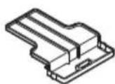
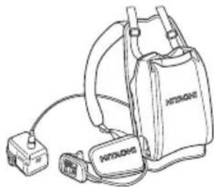
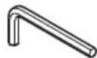
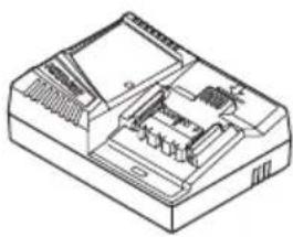
UC36YRSL 329897 6684813
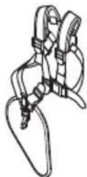
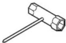
6684764 6699137 335757
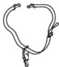
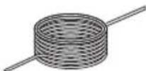
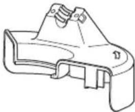
333899 335234 335235
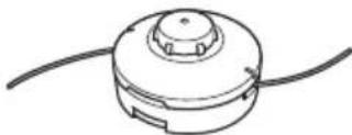
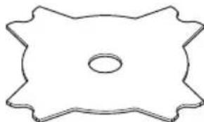
(CG36DL)
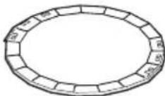
6684768
(CG36DL)
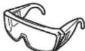
8757696684767

335759
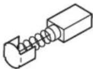
999016
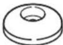
335233
(CG36DL)
335759
(CG36DL)
| English Dansk Română | |||
| GARANTIE CERTIFICATE 1 Model No. 2 Serial No. 3 Date of Purchase 4 Customer Name and Address 5 Dealer Name and Address (Please stamp dealer name and address) | GARANTIBEVIS 1 Modelnummer 2 Serienummer 3 Kebsdato 4 Kundes navn og adrasse 5 Forhandlers navn og adrasse (Indsæt stempel med forhandlers navn og adrasse) | ||
| Deutsch Norsk Slovenžina | |||
| GARANTIESCHEIN 1 Modell-Nr. 2 Serien-Nr. 3 Kaufdatum 4 Name und Anschrift des Kunden 5 Name und Anschrift des Handliers (Bitte mit Namen und Anschrift des Handler abstempelin) | GARANTISERTIFIKAT 1 Modelln. 2 Serienr. 3 Kjepsdato 4 Kundens navn og adrasse 5 Forhandlers navn og adrasse (Vennligst stemple forhandlers navn og adrasse) | ||
| Français Suomi Slovenžina | |||
| CERTIFICATE DE GARANTIE 1 No. de série 2 No de série 3 Date d'achat 4 Nom et adresse du client 5 Nom et adresse du revendeur (Cachet portant le nom et l'adresse du revendeur) | TAKUUTODISTUS 1 Malli nro 2 Sarja nro 3 Ostopävamārā 4 Asiakkaan nimi ja osoite 5 Myjiān nimi ja osoite (Leimaa myjiān nimi ja osoite) | ||
| Italiano Eλλινίκα Βυρarcsκη | |||
| CERTIFICATE DI GARANZIA 1 Modelo 2 N"di série 3 Data di acquirevo 4 Nome e indirizzo dell'acquirente 5 Nome e indirizzo del rivenditore (Si prega di apporre il timbro con quosti dati) | ΠΙΤΟΙΟΙHTΙΚΟ ΕΥΓΗΝΕΗ 1 Ap. Movτέλου 2 Θεμον Αρ. 3 Μερομινια γορός 4 Θονμα κα δειδύνωνη πελάτη 5 Θονμα κα δειδύνωνη μετατιλήτη (Πρακαλούμεν αν ύπομιοτοιθει σφραγιδα) | ||
| Nederland Polski Srpski | |||
| GARANTIEBEWIJS 1 Modelnumber 2 Serienummer 3 Datum van aankoop 4 Naam en adres van de gebruiker 5 Naam en adres van de handelaar (Stempel a.u.b. naam en adres vande de handelaar) | GWARANCJA 1 Model 2 Numer seryjny 3 Data zakupu 4 Nazwaclienta i adres 5 Nazwa dealer i adres (Pieczęc punktu sprozdaź) | ||
| Espanol Magyar Hrvatski | |||
| CERTIFICADO DE GARANTÍA 1Número do modulo 2Número do série 3 Fecha de acquisión 4 Nombre y direccion del cliente 5 Nombre y direccion del distribuidor (Se ruega poner el sello del distribuidor con su nombre y direccion) | GARANCIA BIZONYLAT 1 Tipusszám 2 Sorozatszám 3 A vasafrásá tíatuma 4 A Vázario neve és cime 5 A Kereskedő neve és cime (Kárjúk ide olhelyezni a Kereskedő nevēnek és címenek pecsétjét) | ||
| Portugues Česina Yürscheinényi | |||
| CERTIFICADO DE GARANTIA 1Número do modulo 2Número do série 3 Data de compra 4 Nombre e morada do cliente 5 Nombre e morada do distribuidor (Per favor, carimbe o nome e morada do distribuidor) | ZÁRUÇNI LIST 1 Model c. 2 Série c. 3 Datum nákupu 4 Mýné a adresa zákaznika 5 Mýné a adresa prodejece (Prosime o razitko se jmídem a adresou prodejce) | ||
| Svenska Türke | Rüsskni | ||
| GARANTICERTI KAT 1 Modellnr 2 Serienr 3 Inkópsdatum 4 Kundens namn och adress 5 Försäljarens namn och adress (Stámpla försäljarens namn och adress) | GARANTISERTIFIKASI 1 Model No. 2 Seri No. 3 Satun Alma Tarihi 4 Müşteri Advi ve Adresi 5 Bayi Advi ve Adresi (Lüften bayi admi ve adresini kaçé olarak basin) | ||
HITACHI
| ① | |
| ② | |
| ③ | |
| ④ | |
| ⑤ |
Hitachi Power Tools Europe GmbH
Siemensring 34, 47877 willich, Germany
Tel: +49 2154 49930
Fax: +49 2154 499350
URL: http://www.hitachi-powertools.de
Hitachi Power Tools Netherlands B.V.
Brabanthaven 11, 3433 PJ Nieuwegein, The Netherlands
Tel: +31 30 6084040
Fax: +31 30 6067266
URL: http://www.hitachi-powertools.nl
Hitachi Power Tools (U. K.) Ltd.
Precedent Drive, Rooksley, Milton Keynes, MK 13, 8PJ, U.K.
Tel: +44 1908 660663
Fax: +44 1908 606642
URL: http://www.hitachi-powertools.co.uk
Hitachi Power Tools France S. A. S.
Kjeller Vest 7, N-2027 Kjeller, Norway
Tel: (+47) 6692 6600
Fax: (+47) 6692 6650
URL: http://www.hitachi-powertools.no
Hitachi Power Tools Sweden AB
Rotebergsvagen 2B SE-192 78 Sollentuna, Sweden
Tel: (+46) 859899900
Fax: (+46) 859899940
URL: http://www.hitachi-powertools.se
Hitachi Power Tools Denmark A/S
Lillebaeltsvej 90, 6715 Esbjerg N, Denmark
Tel: (+45) 75143200
Fax: (+45) 75 14 36 66
URL: http://www.hitachi-powertools.dk
Hitachi Power Tools Finland Oy
Tupalankatu 9, 15680 Lahti, Finland
Tel: (+358) 207431530
Fax: (+358) 207431531
URL: http://www.hitachi-powertools.fi
Hitachi Power Tools Hungary Kft.
1106 Bogancsvirag U.5-7, Budapest, Hungary
Tel: +36 1 2643433
Fax: +36 1 2643429
URL: http://www.hitachi-powertools.hu
Hitachi Power Tools Polska Sp.z.o.o.
Modricka 205, 664 48 Moravany, Czech, Republic
Tel: +420 547 422 660
Fax: +420 547 213 588
URL: http://www.hitachi-powertools.cz
Hitachi Power Tools RUS L.L.C.
Kashirskoe Shosse 41, bldg. 2, 115409, Moscow, Russia
Tel: +7 495 727 4460
Fax: +7 495 727 4461
URL: http://www.hitachi-pt.ru
Hitachi Power Tools Romania S. R. L.
Ring Road, No. 66, Mustang Traco Warehouses, Warehouse
No.1, Pantelimon City, 077145, Ilfov County, Romania