
TRB 27EAP - Blower Tanaka - Free user manual and instructions
Find the device manual for free TRB 27EAP Tanaka in PDF.
User questions about TRB 27EAP Tanaka
0 question about this device. Answer the ones you know or ask your own.
Ask a new question about this device
Download the instructions for your Blower in PDF format for free! Find your manual TRB 27EAP - Tanaka and take your electronic device back in hand. On this page are published all the documents necessary for the use of your device. TRB 27EAP by Tanaka.
USER MANUAL TRB 27EAP Tanaka
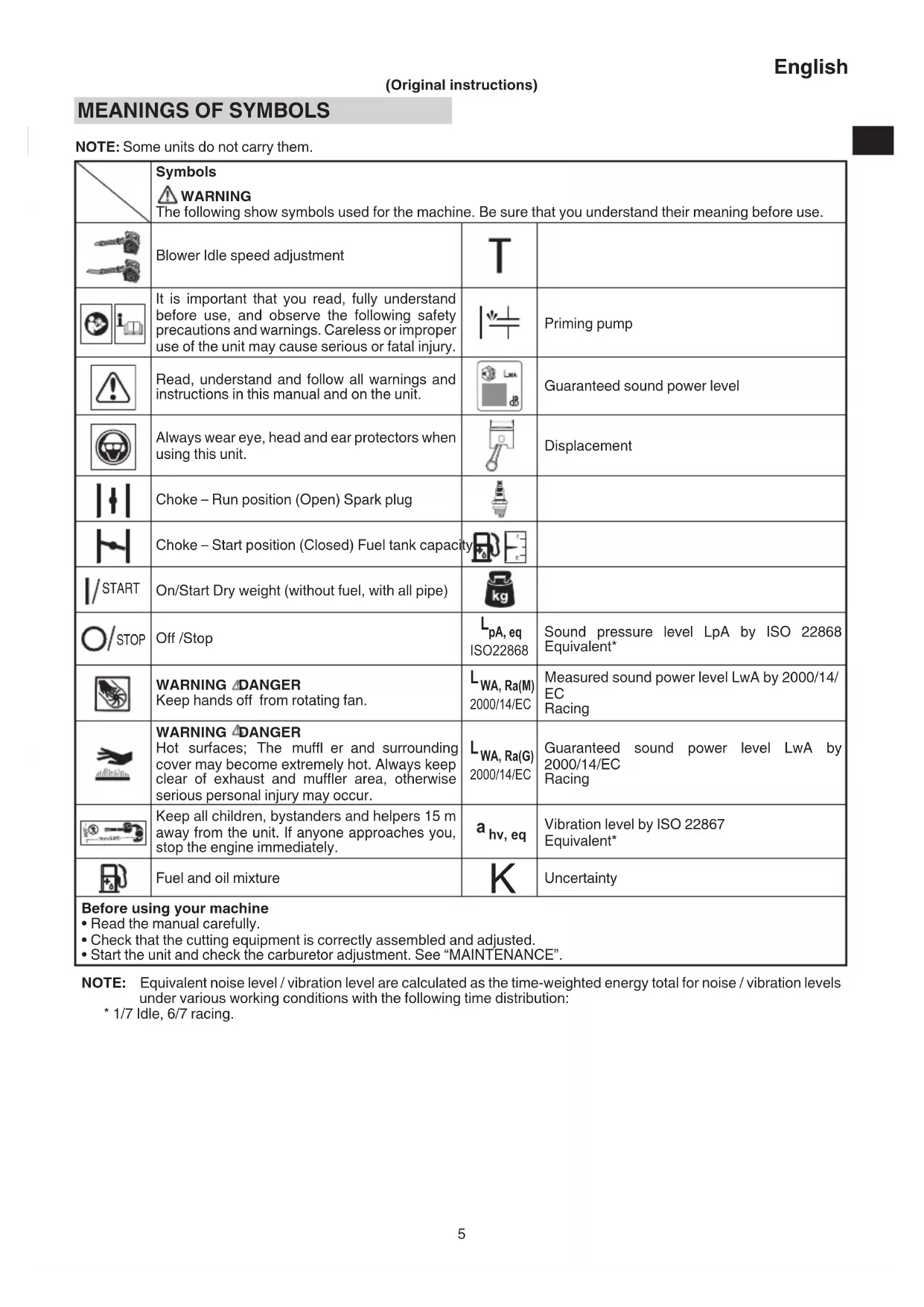
NOTE: Some units do not carry them.
| Symbols WARNING The following show symbols used for the machine. Be sure that you understand their meaning before use. | |||
| Blower Idle speed adjustment | T | ||
| It is important that you read, fully understand before use, and observe the following safety precautions and warnings. Careless or improper use of the unit may cause serious or fatal injury. | Priming pump | ||
| Read, understand and follow all warnings and instructions in this manual and on the unit. | Guaranteed sound power level | ||
| Always wear eye, head and ear protectors when using this unit. | Displacement | ||
| Choke - Run position (Open) Spark plug | |||
| Choke - Start position (Closed) Fuel tank capacity | |||
| I/START | On/Start Dry weight (without fuel, with all pipe) | kg | |
| O/STOP | Off /Stop | LpA, eq ISO22868 | Sound pressure level LpA by ISO 22868 Equivalent* |
| WARNING DANGER Keep hands off from rotating fan. | LWA, Ra(M) 2000/14/EC | Measured sound power level LwA by 2000/14/ EC Racing | |
| WARNING DANGER Hot surfaces; The muffl er and surrounding cover may become extremely hot. Always keep clear of exhaust and muffler area, otherwise serious personal injury may occur. | LWA, Ra(G) 2000/14/EC | Guaranteed sound power level LwA by 2000/14/EC Racing | |
| Keep all children, bystanders and helpers 15 m away from the unit. If anyone approaches you, stop the engine immediately. | ahv, eq | Vibration level by ISO 22867 Equivalent* | |
| Fuel and oil mixture | K | Uncertainty | |
| Before using your machine · Read the manual carefully. · Check that the cutting equipment is correctly assembled and adjusted. · Start the unit and check the carburetor adjustment. See "MAINTENANCE". | |||
NOTE: Equivalent noise level / vibration level are calculated as the time-weighted energy total for noise / vibration levels under various working conditions with the following time distribution:
* 1/7 Idle, 6/7 racing.
WHAT IS WHAT? (Fig. 1)
Since this manual covers several models, there may be some difference between pictures and your unit. Use the instructions that apply to your unit.
A. Fuel cap
B. Throttle trigger
C. Starter handle
D. Fuel tank
E. Carburetor
F. Air cleaner
G. Handle
H. Ignition switch
I. Straight pipe
J. Conic pipe
K. Guard net
L. Spark plug
M. Choke lever
N. Priming bulb
O. Recoil starter
P. Fan-headed pipe
Q. Cruise lever
R. Combi box spanner
S. Handling instructions
T. Knob volt
WARNING AND SAFETY INSTRUCTIONS
Pay special attention to statements preceded by the following words:

WARNING
Indicates a strong possibility of severe personal injury or loss of life, if instructions are not followed.
CAUTION
Indicates a possibility of personal injury or equipment damage, if instructions are not followed.
NOTE
Helpful information for correct function and use.
Operator safety
Wear head protection (1). (Fig. 2)
Always wear a safety face shield or goggles (2). (Fig. 2)
O Wear approved hearing protection (3). (Fig. 2)
Long-term exposure to noise can result in permanent hearing impairment.
Pay attention to your surroundings. Be aware of any bystanders who may be signaling a problem.
Remove safety equipment immediately upon shutting off engine.
Always wear heavy, long-sleeved shirts (4) and long pants (5) and non-slip boots (6) and gloves (7). (Fig. 2)
Do not wear loose clothing, jewelry, short pants, sandals or go barefoot.
Secure hair so it is above shoulder length.
Do not operate this tool when you are tired, ill or under the influence of alcohol, drugs or medication.
Do not operate the tool at night or under bad weather conditions when visibility is poor. And do not operate the tool when it is raining or right after it has been raining.
Working on slippery ground could lead to an accident if you lose your balance.
- Never let a child or inexperienced person operate the machine.
- Do not start the engine if there are any flammables such as dry leaves, waste paper or fuel in the vicinity.
- Never start or run the engine inside a closed room or building. Breathing exhaust fumes can kill.
- Keep handles free of oil and fuel.
- Keep hands away from moving part or heated area.
Do not grab or hold the unit by the blow pipe. - When the unit is turned off make sure the engine has stopped before the unit is set down.
- When operation is prolonged, take a break periodically so that you may avoid possible Hand-Arm Vibration Syndrome (HAVS) which is caused by vibration.
WARNING
Always operate the tool with proper protective equipment and clothing. Failure to do so may result in accidents such as burns or injuries. (Fig. 2)
- Do not touch the spark plug area or high voltage during operation. Doing so may result in electric shock.
Do not allow children near the tool during operation.
Do not touch the engine, top cover or exhaust vent during or shortly after operation. Doing so may result in burn or injury.
Antivibration systems do not guarantee that you will not sustain Hand-Arm Vibration Syndrome or carpal tunnel syndrome. Therefore, continual and regular users should monitor closely the condition of their hands and fingers. If any of the above symptoms appear, seek medical advice immediately.
Since this product is engine driven, make sure to wear the proper protective equipment to minimize the effect of vibration and sound to your body. Limit a single continuous operation between 30 to 40 minutes, and rest for 10 to 20 minutes. Also, limit your day's work time to 80 minutes.
If you are using any medical electric/electronic devices such as a pacemaker, consult your physician as well as the device manufacturer prior to operating any power equipment.
- If trash or collected waste including fallen leaves become trapped in the machine, make sure to cut the engine and remove the debris before resuming use. Using the machine without removing the obstructions may result in damage.
Unit/machine safety
Inspect the entire unit/machine before each use. Replace damaged parts. Check for fuel leaks and make sure all fasteners are in place and securely tightened.
Replace parts that are cracked, chipped or damaged in any way before using the unit/machine. Faulty parts may increase the risk of accidents and may lead to an injury.
- Keep others away when making carburetor adjustments.
- Use only accessories as recommended for this unit/machine by the manufacturer.
Before operation, make sure that there are no tools such as the adjustment key or spanner still attached to the unit.
WARNING
- Never modify the unit/machine in any way. Do not use your unit/machine for any job except that for which it is intended.
- Tampering with the engine voids the EU type approval of this engine.
Non-authorized modifications and/or accessories may result in serious personal injury or the death of the operator or others.
The guard net must be firmly fixed in place.
Fuel safety
Mix and pour fuel outdoors and where there are no sparks or flames.
O Use a container approved for fuel.
- Move at least 3m away from fueling site before starting engine.
- Stop engine before removing fuel cap. Do not remove the fuel cap during operation.
- Empty the fuel tank before storing the unit/machine. It is recommended that the fuel be emptied after each use. If fuel is left in the tank, store so fuel will not leak.

WARNING
Fuel is easy to ignite or get explosion or inhale fumes, so that pay special attention when handling or fi Iling fuel.
- Do not smoke or allow smoking near fuel or the unit/machine or while using the unit/machine.
O Wipe up all fuel spills before starting engine.
- Store unit/machine and fuel in area where fuel vapors cannot reach sparks or open fl ames from water heaters, electric motors or switches, furnaces, etc.
- When using the unit in dry areas, make sure that fire extinguishing equipment is readily available.
If you shut off the engine for refueling, make sure the unit has cooled down before adding fuel.
Blowing safety
-
Operate unit/machine only at reasonable hours - not early in the morning or late at night when people might be disturbed. Comply with times listed in local ordinances. Usual recommendations are 9:00 a.m. to 5:00 p.m., Monday through Saturday.
-
Never direct discharge of air toward bystanders nor allow anyone near the area of operation. Use care in directing discharge to avoid glass enclosures, automobiles, etc.
Check the work area and surroundings for empty cans, metal pieces and other obstructions which could cause injury, accident or damage. If there are any of these objects in the area, remove them in advance.
Stay alert for uneven sidewalks, holes in terrain or other unstable condition when using the tool.
Take all possible precautions when leaving the tool unattended such as stopping the engine.
-
Never operate the tool without blow pipes or other protective device in place. (If so equipped.)
-
Keep others including children, animals, bystanders and helpers outside the 15m hazard zone. Stop the engine immediately if you are approached.
Please exercise caution as engine startup may be delayed after pulling the starter handle.
Always keep the engine on the right side of your body.
-
Keep firm footing and balance. Do not over-reach. Losing your balance during work may lead to an injury
-
Keep all parts of your body away from the muffler when the engine is running.
Always carry a first-aid kit when operating any power equipment.
-
Avoid prolonged use at low speed range in which vibration is high. Doing so may result in engine damage.
-
When relocating to a new work area, or inspecting, adjusting or exchanging the unit's accessories, etc., be sure to shut off the machine.
-
Never place the machine on the ground when running.
If you accidentally bump or drop the unit, inspect it immediately to make sure there are no damage, cracks or deformations.
If the tool is operating poorly and produces strange noise or vibrations, turn off the engine immediately and ask your dealer to have it inspected and repaired.
Continued use under these conditions could lead to injury or tool damage.
Use in accordance with local laws and regulations.
- Loosen deposits with a rake or a broom before starting any exhaust or vacuum work.

WARNING
Work from ladders or high place (such as roofs) is prohibited and could result in severe injury.
Maintenance safety
-
Maintain the unit/machine according to recommended procedures.
Disconnect the spark plug before performing maintenance except for carburetor adjustments.
Keep others away when making carburetor adjustments. -
Use only genuine Tanaka replacement parts as recommended by the manufacturer.
CAUTION
Do not disassemble the recoil starter. There is a possibility of personal injury with recoil spring.
WARNING
Improper maintenance could result in serious engine damage or in serious personal injury.
Transport and storage
- Carry the unit/machine by hand with the engine stopped and the muffler away from your body.
- Allow the engine to cool, empty the fuel tank, and secure the unit/machine before storing or transporting. Failure to do so may result in fire or accidents.
- Empty the fuel tank before storing the unit/machine. It is recommended that the fuel be emptied after each use. If fuel is left in the tank, store so fuel will not leak.
- Store unit/machine out of the reach of children.
Clean and maintain the unit carefully and store it in a dry place. - Make sure engine switch is off when transporting or storing.
- You have to secure the machine during transport to prevent loss of fuel, damage or injury.
If a warning label cannot be read, peels off or becomes indistinct, replace it with a new one. To purchase new labels, contact Tanaka dealer.
If situations occur which are not covered in this manual, take care and use common sense. Contact Tanaka dealer if you need assistance.
SPECIFICATIONS
The SPECIFICATIONS of this machine are listed in the table on page 192.
NOTE
All data subject to change without notice.
ASSEMBLY PROCEDURES
WARNING
Make sure the engine is turned off/stopped and not hot before assembly.
Blow pipes to main body (Fig. 3)
Inspect the main body and accessories.
Connect straight pipe (I) securely. Align projection (8) in straight pipe with groove (9) on blower housing and slide the pipe into the blower housing.
Rotate the pipe clockwise to lock it into place.
Nozzle to straight pipe (Fig. 4 - 5)
[TRB27EAP]
Align groove (9) on the conic pipe (J) and projection (8) on straight pipe (I) and rotate the conic pipe in place. [TRB27EP]
Align groove (9) on the Fan-Headed pipe (P) and projection (8) on straight pipe (I) and rotate the Fan-Headed pipe in place.
NOTE [TRB27EP]
(Optiona)
Vacuum attachment is offered as an optional kit which converts the hand-held blower into a vacuum cleaner. For installation see Vacuum kit THV-260 (TRB27EP) manual.
(Safety future)
If you try to open the guard net (K) when engine is running, it will automatically stop the engine. (Fig. 1) But never try to open the guard net (K) when engine is running even with this future, otherwise serious personal injury may occur.
OPERATING PROCEDURES
Fuel (Fig. 6)

WARNING
The unit/machine is equipped with a two-stroke engine. Always run the engine on fuel, which is mixed with oil. Provide good ventilation, when fueling or handling fuel.
- Fuel is highly flammable and it is possible to get seriously injured when inhaling or spilling on your body. Always pay attention when handling fuel. Always have good ventilation when handling fuel inside building.
Fuel
Always use branded 89 octane unleaded gasoline.
- Use genuine two-cycle oil or use a mix between 25:1 to 50:1, please consult about the mixture ratio to Tanaka dealer.
If genuine oil is not available, use an anti-oxidant added quality oil expressly labeled for air-cooled 2-cycle engine use (JASO FC GRADE OIL or ISO EGC GRADE). Do not use BIA or TCW (2-stroke water-cooling type) mixed oil.
Never use multi-grade oil (10 W/30) or waste oil.
- Never mix fuel and oil in machine's fuel tank. Always mix fuel and oil in a separate clean container.
Always start by filling half the amount of gasoline, which is to be used.
Then add the whole amount of oil. Mix (shake) the fuel mixture. Add the remaining amount of gasoline.
Mix (shake) the fuel-mix thoroughly before filling the fuel tank.
Mixing amount of two-cycle oil and gasoline
| Gasoline (Liter) | Two-cycle oil (ml) | |
| Ratio 50:1 Ratio | 25:1 | |
| 0.5 10 | — | 20 |
| 1 20 | — | 40 |
| 2 40 | — | 80 |
| 4 80 | — | 160 |
Fueling

WARNING
Always shut off the engine and let it cool for a few minutes before refueling. Do not smoke or bring flames or sparks near the fueling site.
- Slowly open the fuel tank, when filling up with fuel, so that possible over-pressure disappears.
- Tighten the fuel tank cap carefully, after fueling.
Always move the unit at least 3m from the fueling area before starting.
Always wash any spilled fuel from clothing immediately with soap.
Be sure to check any fuel leakage after refueling.
Before fueling, in order to remove static electricity from the main body, the fuel container and the operator, please touch the ground that is slightly damp.
Before fueling, clean the tank cap area carefully, to ensure that no dirt falls into the tank. Make sure that the fuel is well mixed by shaking the container, before fueling.
Starting
CAUTION
Do not start if the pipe and guard net is obstructed.
(1) Starting the cold engine
1. Set ignition switch (H) to ON position. (Fig. 7)
2. Push priming pump (N) several times so that fuel flows through return pipe (10). (Fig. 8)
- Set choke lever (M) to START position (closed) (A). (Fig. 9)
- Pull starter handle briskly, taking care to keep the handle in your grasp and not allowing it to snap back. (Fig. 10)
- When you hear the engine want to start, return choke lever to RUN position (open) (B). (Fig. 9)
- Pull starter handle briskly again. (Fig. 10)
NOTE
If engine does not start, repeat procedures from 2 to 6.
- Then allow the engine about 2-3 minutes to warm up before subjecting it to any load.
(2) Starting the warm engine
Use only 1, 2 and 6 of the starting procedure for a cold engine.
Operating blower (Fig. 11)
A low speed should be used to blow leaves and dry grass.
A medium speed should be used to clean wet leaves and grass.
A high speed should be used when moving gravel, dirt or other heavy materials.
- When working in a dusty area, hose down the area with water.
WARNING
Do not direct discharge of air toward people or pet.
The unit should be operated in a well ventilated area.
- Never perform assembly or disassembly procedures with engine running or serious personal injury may result.
- Never touch muffler, spark plug, or other metallic parts while engine is in running or immediately after shutting off engine.
Do not use this blower indoors.
- Do not operate if there is an open window near the work area and its surroundings.
CAUTION
This blower has been designed and adjusted to be used with blowing pipes attached. It must never be operated without the straight pipe.
NOTE
- When you hear or feel strange sound or vibration, stop engine immediately and check if anything blocks fans or pipes. If so, remove it and check for damage.
Blowing Pipe Selection
Straight Blowing Pipe
Allows operation at maximum blow capacity.
Suitable for operation in widespread areas, engine revolution is kept at a minimum, resulting in improved fuel consumption when compared with the conic/fanshaped blowing pipe.
The straight blowing pipe is recommended for normal use.
- Conic/Fan-Shaped Blowing Pipe
Allows operation at maximum blow speed.
Ideal for blowing wet leaves stuck to the ground or releasing a powerful air discharge in limited spaces.
Stopping (Fig. 12)
Decrease engine speed and run at an idle for a few minutes, then turn off ignition switch (H) and keep the pressed until the engine comes to a complete stop.
MAINTENANCE
MAINTENANCE, REPLACEMENT OR REPAIR OF THE EMISSION CONTROL DEVICES AND SYSTEMS MAY BE PERFORMED BY ANY NON-ROAD ENGINE REPAIR ESTABLISHMENT OR INDIVIDUAL.
Carburetor adjustment (Fig. 13)
The carburetor is a precision part that mixes air and fuel, and it is designed to ensure high performance from the engine. Before the tool is shipped from the factory, its carburetor is adjusted during a test run. Only make adjustments if it is necessary because of environmental conditions (the climate or atmospheric pressure), the type of fuel, the type of two-cycle oil, etc.

WARNING
Because the carburetor is manufactured with a high degree of precision, do not disassemble it.
For this product, the only setting of the carburetor that can be adjusted is the idle speed (T).
T = Idle speed adjustment screw.
Idle speed adjustment (T)
Check that the air filter is clean. If adjustment is required, turn IDLE speed Adjustment Screw (T) close (clockwise) to increase engine speed, open (counterclockwise) to decrease engine speed. Standard Idle rpm is 2800-3200 rpm.
CAUTION
The above adjusting procedure must be followed when adjustment is MADE or DAMAGE to engine will occur because of the incorrect condition.
NOTE
Some models sold areas with strict exhaust emission regulation do not have high and low speed carburetor adjustments. Such adjustments may allow the engine to be operated outside of their emission compliance limits. For these models, the only carburetor adjustment is idle speed.
RECOMMENDATION
CARBURETOR ADJUSTMENT NEEDS THE SKILL OF EXPERIENCES OR WELL TRAINED PEOPLE, OR IS RECOMMENDED TO TAKE THE UNIT TO TANAKA DEALER.
Air fi lter (Fig. 14)
The air filter (11) must be cleaned from dust and dirt in order to avoid:
Carburetor malfunctions.
O Starting problems.
Engine power reduction.
Unnecessary wear on the engine parts.
Abnormal fuel consumption.
Clean the air filter daily or more often if working in exceptionally dusty areas.
Cleaning the air fi I ter (Fig. 14)
Open the air filter cover (12) and remove the air filter (11). Clean it.
Check that the filter is dry before reassembly.
An air fi liter that has been used for some time cannot be cleaned completely. Therefore, it must regularly be replaced with a new one. A damaged fi liter must always be replaced.
Fuel fi Iter (Fig. 15)
Remove the fuel filter (13) from the fuel tank, and replace it if it is dirty.
NOTE
A blocked fuel filter (13) can prevent the supply of fuel and cause a rotation malfunction of the engine.
Spark plug (Fig. 16)
When removing the spark plug, twist and remove the plug cap covering the spark plug as shown in the illustration. (Fig. 17)
The spark plug condition is influenced by:
An incorrect carburetor setting.
Wrong fuel mixture (too much oil in the gasoline)
O A dirty air fi filter.
O Hard running conditions (such as cold weather).
These factors cause deposits on the spark plug electrodes, which may result in malfunction and starting difficulties. If the engine is low on power, difficult to start or runs poorly at idling speed, always check the spark plug first.
If the spark plug is dirty, clean it and check the electrode gap. Re-adjust if necessary. The correct gap is 0.6mm
The spark plug should be replaced after about 100 operation hours or earlier if the electrodes are badly eroded.
NOTE
In some areas, local law requires using a resistor spark plug to suppress ignition signals. If this machine was originally equipped with resistor spark plug, use same type of spark plug for replacement.
For long-term storage
Drain all fuel from the fuel tank. Start and let engine run until it stops. Repair any damage which has resulted from use. Clean the unit with a clean rag, or the use of high pressure air hose. Put a few drops of two-cycle engine oil into the cylinder through the spark plug hole, and spin the engine over several times to distribute oil.
Cover the unit and store it in a dry area.
Maintenance schedule
Below you will find some general maintenance instructions. For further information please contact Tanaka dealer.
Daily maintenance
Clean the exterior of the unit.
Check that the air intake at the guard net is not clogged.
Check the guard net for damage or cracks. Change the guard net in case of impacts or cracks.
Check that nuts and screws are sufficiently tightened.
Weekly maintenance
Check the starter, especially the cord.
Clean the exterior of the spark plug.
- Remove the spark plug and check the electrode gap. Adjust it to 0.6mm , or change the spark plug.
Clean the air fi Iter.
Monthly maintenance
- Rinse the fuel tank with gasoline, and clean fuel filter.
Clean the exterior of the carburetor and the space around it.
Quarterly maintenance
Clean the cooling fins on the cylinder.
Clean the fan and the space around it.
Clean the muffler of carbon.
CAUTION
Cleaning of cylinder fins, fan and muffler shall be done by a Tanaka dealer.
SELECTING ACCESSORIES
The accessories of this machine are listed on page 193.
SELECTING ATTACHMENTS
Recommended accessories for each model are presented in the table below.
For purchases, contact Tanaka dealer.
Please check carefully as those accessories not marked with "●" cannot be attached.
List of recommended accessories
| Code No. Description TRB27EAP | TRB27EP | |
| 6601600 NOZZLE (A) | ● | ● |
| 6698394 NOZZLE (B) | ● | ● |
| 6699184 FAN-HEADED PIPE | ● | ● |
| 6601634 VACUUM KITTHV-260 (TRB27EP) | - | ● |
| 6684946 VACUUM PIPE - | ● | |
| 6601497 BENT PIPE - | ● | |
| 6601601 DUST BAG - | ● | |
| 6601500 EARTH GRIP - | ● |
TROUBLESHOOTING
Use the inspections in the table below if the tool does not operate normally. If this does not remedy the problem, consult your dealer or the Tanaka dealer.
| Condition Cause Remedy | |||
| Engine does not start | Fuel system | Fuel tank is empty or fuel level is low | Fill the fuel tank with the correct fuel mix (25:1-50:1) |
| Fuel tank contains old fuel (off ensive odor) | Replace with new fuel | ||
| Too much fuel is absorbed and spark plug is wet | 1. Disconnect the spark plug and allow to dry 2. Pull the starter handle 5 or 6 times to remove the surplus fuel 3. Attach the spark plug 4. Set the choke lever to RUN position and pull the starter handle | ||
| Fuel filter is clogged with dirt | Clean the fuel filter | ||
| Fuel pipe is bent or disconnected | Ensure that the fuel flows smoothly | ||
| Carburetor malfunction Contact Tanaka dealer | |||
| Electrical system | Stop switch lead has short-circuited Cont | act Tanaka dealer | |
| Spark plug is dirty Replace or clean the spark plug | |||
| Electrode gap is too big Adjust the gap to | 0.6 mm | ||
| Poor connection between high tension cable and spark plug | Reconnect | ||
| Electrical system malfunction Contact Tanaka dealer | |||
| Other | Muffler exhaust port is clogged with carbon | Contact Tanaka dealer for repair | |
| Engine starts but cuts out straightaway Engine is apt to cut out | Fuel system | Fuel tank is empty or fuel level is low | Fill the fuel tank with the correct fuel mix (25:1-50:1) |
| Fuel tank contains old fuel (off ensive odor) | Replace with new fuel | ||
| Two-cycle oil has not been added Contact Tanaka dealer | |||
| Choke lever is in START position Set the | choke lever to RUN position | ||
| Air has got into fuel system Reconnect the | fuel pipe or joint | ||
| Carburetor malfunction Contact Tanaka dealer | |||
| Electrical system | Ignition failure | ||
| Spark plug failure Replace with new | spark plug | ||
| Electrical system failure | Contact Tanaka dealer | ||
| Other | Engine overheating | ||
| Wrong spark plug model | Replace with designated part See "SPECIFICATIONS" | ||
| Dirty air cleaner | Clean | ||
| Carbon clogging (muffler exhaust port) | Clean | ||
| Insuffcient compression (piston, piston ring, cylinder) | Contact Tanaka dealer | ||
| Abnormal vibration | Handle, handle bracket or other fastening part is loose | Check and tighten | |
| Engine does not stop | Stop switch failure | Set the choke lever to START position to stop the engine Cease use immediately and contact Tanaka dealer | |
| Engine stops when throttle is closed | Idle speed is too low | Contact Tanaka dealer | |
SYMBOLBEDEUTUNGEN
SELECTION D'ACCESSIONS
WAARSCHUWINGEN EN VEILIGHEIDSINSTRUCTIES
ACCESSIONS SELECTEREN
HVAD ER HVAD? (Fig. 1)
MEGJEGYZES [TRB27EP]
(Öpçionalis)
- 1/7 in gol, 6/7 accelerator.
DESCRIEREA PIESELOR (Fig. 1)
IPEdUynpeKJdeHnN HhCTpyKcN 3A Be3OpACHOCT
O6bphete cneuaHOBHNMaHHe Ha cIeHnTe n3IOKeHHa:
PNEyNPEKDEHNE
Yka3Ba roJMa BepoTHOCT OT cepno3HO HapaHBAHe IIN 3aY6a Ha JHBOT, aKO INHCTpyKcINTe He 6bDat CLeDbAHN.
BHIMAHNE
YKa3Ba BepoTHOCT OT cepno3Ho HapaHbAHe IINIeTN Ha o6OpyDbaHeTo, aKO INHCTpyKcHnTe He 6bDaT CJeDbAHN.
3ABEJIeHHA
I0JIe3Ha INΦOpMaζη 3a IpaBnIHOTo ΦyHKUOHOHPaHe N I3PON3BaHe.
Be3onacnoct Ha onepaTopa
Hocete 3aunTHn cpeCTBa 3a rnaBata (1). (Фиг.2)
O BnHaHn Hocete JInCeB npedna3nteI nn 3aunTHn ouHa (2). (Φnr. 2)
O Poi3BaIte OdopeHn 3aunTHn cpeCDTba 3a cnlyxa (3). (Фиг.2)
IpoBbJIHnTeJIHOTo 3JIaHaHe Ha Wm MoKe Da DOBeDe Do TpaHn CnyXOBu YBpeKdAHn.
Obphe Te BnMaHHe Ha 3aObHaJyAaTa BN cpeJa.
ImaTe ppeBnD BCnUKn, CTOnu Ha 6n3o Xopa,
KoNTO MoKe Da CnHaJIIn3npa 3a npo6JeM.
OctpaHTe oBe30nacHTeJIHOTo 6OpdyBaHe He3a6abHo cIeI N3KIOUbaHe Ha DBuRaTeJI.
O BnHaHn HocTe TeKKn 6Iy3n C IbIbIg PbKaB (4), IbIgnaHTaIOHn (5), HeNtB3raun Ce oSyBkn (6) n PbKaBUN (7). (ΦnR.2)
He hocTe wnpOn npexn, 6nKytA, Kbcn nHaTaNHOH, caHdJIH N He xOJeTe 6oCn.
ФИКСИРайТе КOCaTа,ТаKaЧe Дa e HaДБЛЖИнHaHaJaPamHeTe.
He pa6oTeTe CTo3n HcHCTpyMeHT, KOraTO cTe N3MopeHN, 60JIHN IIN IOB Bb3dEJcTBHeTO Ha aIKOXOJ, JekapCTBa IIN ONIATN.
He pa6oTeTe c To3n ypei npe3 HoUta HIN KOraTO KInMaTnUHnTe ycIOBnI ppeIraT lo7a BnIMOCCT. Cbio TaKa, He n3noJI3BaIte ypeJa DOkato BAII INN BeHaRa, cJeI KaTO dKdEe T e CnpJl.
Pa6oTaHaXb3raBa NOBbpxHOCT MoHe Da DOBeDe Do HnUeHTn, aKo 3aRy6bnte paBHOBeCne.
HnKora He octabRte Dea nn Lnua 6e3 onnt da pa60rT C MaunHaTa.
He nychaTe DnurateTna kOHaOKoNm3anaHIMNo6eKTH KATO CYXN JnCTa,OTnAHa XAPTNnIINrOpHB.
HnKora He cTaptnpaIte Hne nychaIte DnIraTeB 3aTBOpena CTAI nn crpaJa. BnIWBaHeTo HaOTpa6oTeHr ra3OBe MoKe Da DOBeDe Do CMbPT.
O PdIbPkaHTe dpbHKnTe YnCTN OT MacNo IropnBO.
O DpbkTe pbcTe Cn daJeU OT dBNKeuTE ce qactn nn ropeuTe 30H.
He XBaauTe Hn He DpBKeypea 3a BENTINlaUOnHnTa Tpb6a.
O KoroTo ypeBt e n3Kluoyen, npeDn da ocTaBnTe ypeDa, ce yBepeTe, ye MOTopbT e cnpaI.
O Korato pa6oTaTa e npoBnJnTeJIHa, npaBeTe nepnoDnHn NOuBKn, TaKa Ye Da n36eHHe T B3MOKeH cnHdPOM Ha Bn6paCn pKa-pamO (HAVS), KoiTo ce npuynHraBa OT Bn6paCnTa.
IPEyPENKDEHNE
O BnHaH npaboTe c ypea c noDxOJaTa 3aunTHa eKnnpOBka n o6JeHIO. B npotNBEN CnyaH cbIeCTByBa pNCK OT HnCnDEHTN KaTO n3rApRnHn HapaHbAHn. (Фиr.2)
He ninnate o6nactTa Ha cBeuNTe nn Ha BncoKo HanpeKeHne no Bpeme Ha pa6ota. B npotnbEn cnuyaMooKeTe da nolvHTe TOKOB yap.
He octabryte deca da ce npnbnaBaT do HnHCTpyMeHTa NO BpeMe Ha pa60ta.
He DOKOCBaIe TDbIgatela, ropnna Kanak nnn OTxOHaTa KJana No BpeMe nn cKopo cJe padota. B npOTuBEN CnyaM MoKeTe da NpOyUte n3rapAne nnn HapaHBAhe.
ANTINBn6paHNOHHTE CNTeMn He rapaHTnpaT,Ye HMa Da CTpaDATE OT CnHDPOM Ha BN6paunpKa-pamO nn CnHDPOM Ha KapnaJHn TyeJI. ETo 3aio, KpaHnTe NOTpe6nteN, KOINTo pa60rT npOdbJHKTeHNO n peYyRnHO CypeDA, Tp6Ba Da CLEdT NOCTOHPObCte INPbCTHtE CN.AKO e HaNueH KOITOn n da e OT ROPHnTE CmMTOMN, NOTbpCte He3a6abHO MeuHcKApOMU.
O TbI KaTo To3n npOdyKT e 3aDnBnBHaB ON DBnRaTeJ, He 3a6paBnTe Da HOCHT NOxODAIO 3aunTHo 06OpyDbAHe, 3a Da CBeDeTe Do MNHmym Bb3dEhCTBnETo Ha Bn6paunTe N 3ByKa Bbpxy TlNOTo cn. OpranuYBaIte eHa HenpeKbChata Onpaunr MeNdy 30-40 MInHyTn n OCTaBeTe ypeDa Ja noCuBa 3a 10-20 MInHyTn. CbIo TaKa, orpaHnUaBnTe pa6oTaTa cn Do 80 MInHyTn Ha DeH.
Ako n3noI3BaTe KaKBnTo n da e MeiunHCHNeEeKtpnueckn/eJeKtpoHHN yCTpOcTBa KaTO neICMeNkbp, KOHCyItnpaIte Ce cbc CBOJ Iekap, KaKTo n C npOn3BODntel Ha yCTpoCTBOTo, npEn Da pa6oTHe C eJeKtpooobopyDbaHe.
Ako B MaunHaTa NMa Cb6paHn 60KJnyu nn Cb6paHn OTNaDbuN, BHIOHTeHNO NaHaN JIcTaN, BHIMATEHO OTKaueTe DBnraTeN nOTCTpaHHe OCTaTBuN, npEn Da BB3o6HOBHTe pa6Ota TcN. H3noJ3BaHTo Ha MaunHaTa 6e3 OTCTpaHBAHe Ha npenTCTBnTa MoKe Da DOBeDe Do NOBpeDa.
Be3onacnoct Ha ypea/MaunHaTa
O HncKeTpaIte ueJype/MaunHa npEIN BcHOn 3n0JI3BaHe. CmeHeTe NOBpeDeHITe YactN. IpOBepTe 3a TeOBe Ha rOpINBO nCe yBepTe, Ye BCNUK KpeEnK Ca HA MeCTaTa CN N Ca 3aTeRHaTHn Do6pe.
O CMeHeTe YactHtE, KOHTo Ca HanykaHn, HaUbpeHn HnI NIOBpeHn NO HRAKbB HauHn, IpeDn Da 3aNoCHeTepabota CypeA/MaunHaTa. NObpeHn Yactn MoRat da IOBnWAT PnCKa OT INuJeHTN n Da DOBeEdTdo HapaHraBaHn.
He no3B0JIaIe Ha OKoJIHnTe da ce np6JIuHaBaT, KOrato peryInpate Kap6ypatopa.
O N3noJ3BaIte cAmO aKceCoapn, npenopbuaHn OT npOn3BODInTeJIra 3a To3N ypeJ/MaunHa.
O Ipei npabota, yBepete ce, ye Ha MaunHaTa HMa octaHaJI nperyInpaui ngaeHn KIOUOBE.
PNEyNPEXDEHNE
O HnKora He MoiNfuiupaTte ypea/MaunHaTa no KaKBTO n da e hauH. He n3noJI3BaIte cBoA ypeJ/ MaunHa 3a npya pa6oTa, oCBen 3a Ta3n, 3a KOrTo e npedHa3HaueHa.
MaHnnyIpaHeTo Ha DnRaTeIa anyInpa TInOBOTo Odo6peHne Ha EC 3a To3n DnRaTeI.
O HesperlameHTnpaHnTe MoNΦnKaunn N/nn aKceCoapn MOrat Da DOBeDaT Do cepNo3HN TeJeCN HapaHraBaHn nn CmBpT Ha OpeaTopa nn DpyrN.
3aunthata Mpeka Tpra6Ba da 6bJe 3dpabo 3aKpeeneHa Ha MRCTO.
Be3onachoc73a ropHBOTO
CMecBaIte 3apeHdaIte rOpNBOTo Ha OTKpnto KbTeTO HMa NCKpn NII NJaMbU.
O H3noJ3BaIte KOHTeHep, Oo6peH 3a rOpNBO.
O IpeMeCTeCe NOHe Ha 3 M OT MAcTOTO Ha 3apeHdaHe C rOpNBO, npeDn Da CTapTtPaTe DBrTaTeIa.
O N3KIOUeTe DnIgAteJIa, PpeIN Da CBAJIte KanaYKaTa Ha pe3epBoapa. He CBAJIte KaNaYKaTa Ha pe3epBoapa No Bpeme Ha pa6oTa.
O H3npa3Hete roPbHNp e3epBoap, ppeDn da np6epeTe ypeDa/MaunHaTa 3a cbxpaHeHne. PpenopbHTeJHO e rOpBOTO Da 6bDe n3TOBaHO cIeB C9AKO NOI3BaHe.AKO rOpBOTO 6bDe ocTaBeHO B pe3epBoapa,cbxpaHbaIe TaKa,Ye Da HMa TeOBE.
PNEyPENKDEHNE
O TropnbTo e IecHO 3anaJIHMo, B3pNbBOOnaCHO H3nycKa OTPOBHN 3napeHNA, Taka Ye 6pbuaTe CneuHaHO BHIMAHHe npa6oTa n 3apeKdaHe Ha rOpNBO.
He npweTe Hn He no3BolraBe Te npweH e 6n3oCT Do TropNBOT O Nn ypea/MaunHaTaNn DOKaTO N3NOJ3BaTe ypea/MaunHaTata.
O N36bpuete BcKaHbN pa3JIbBaHn, npeI Na CTapTIPaTe DBrTaTeJ.
O CbxaHraBaIte ypea/MaunHaTa n ropnBoto Ha MxCTo, KbTeTo n3napenrta OT ropnBoto He MoRaT a DOCTnHAT Do hckpn Hn OTKpnt PnAmbk OT BoJIepn, eJekTpOMOTOpn Hn IpBkIIIOuBaTeIn, fypHn n np.
O Horato n3noJ3BaTe ypeDa B cyxu paOnH, yBepTe ce, ye pa3noJaTaTe c noKaporacHTeN noD pKa.
AHO n3KIOHTe DnIgTaTeJIa npe3apeKdAnHe, yBepTe ce, ye ypeBt E n3CTnHaI, npEi Da do6abNTe rOpNBO.
Be3onacnoct npn n3dyXbaHe
O Pa6oTeTe C ypeDa/MaunHaTa cAmo B pa3ymHo BpeMe - He paHO cyTpH Nn KbCHO Beepe, B Te3n YacObe MoKeTe Da npITeCHHTe DpyrX opa.
Cna3BaHTe cpoKOBete, yKa3aHN B MeCTHIne Hape6n. IpenOpbuaHTo BpeMe 3a pa60Ta e ot 9:00 do 17:00 Yaca, OT NOHeDeJIHHK Do Cb6Ota.
Hnkora He HacouBaHTe OTdEJIaHETo Ha Bb3DyXa KbM MNHyBaHTe, HnTO N03BOJIABaHTe Ha HnKOrO da ce Do6nKaBA Do 3oHaTa Ha DeIcTBne. ObpHeTe BHMaHHe Ha HACOVAHeTo Ha n3XBbPJIaHETo, C cIe Da ce n36erHat CTbKJIeHN 3arpaJKeHnA, ABTOMOBUNn np.
O IpoBepete pa60THOTo MCTO N OKOJIHOCCTTa 3a npa3HN KytHn, MetaJIHn Yactn HpyrN PpeIYTCTBnR, KOHTo MORa Tda npuHHrT HapaHbAHe, 3IOJOnyKa nn nobpeDa. Ako nMa TaKInBa PpeMTe B paNoHa, OTcPaHeTe rnpEdBapntelHO.
O Korato H3noJ3BaTe INHCTpyMeHTa, BHIMaBaIte 3a HepaBHomepeHn TpToApn, Dynn B TepeHa nn DpyrN HeCTa6uHn YCIOBnA.
O Korato octabte HNCTpyMeHa 6e3 Ha3Op, B3eMeTe BCnKn Bb3MOHN PpeDnA3Hm MepKn, KaTO CNIPAHe Ha DBuRaTeJIa.
HnKora He pa6oTeTe c HnCTpyMeHTa 6e3 BeHTnlaunOHn Tpb6n nn Dpyr0 3aunTHO yctpoiCTBO. (aKO ce npedna).
O DpbkTe Dpyrnte Xopa, BKNIOHTeJIHO Deca, HINBOTHN, OKoJHn I NOMOuHnI Ha 15 MeTpA N3BbH ONaCHaTa 30Ha. CnpTe DnRaTeJIr He3a6abHo, aKO Bn np6nKAT.
O MoJr npoRBAaTe BnMaHne, TbK aTO BnIOuBaHTo Ha DnIraTeJI MOKe Da ce 3a6abN CJeD n3DbpNbaHe Ha CTapTepHnI loCT.
O BnHaHn DpbXTe DnRaTeIaOT DaChata CtpaHa Ha TAnlOTo CN.
O PnIbpaHKe CTa6HHa CToHka 6aHaHC.He ce Do6HkBaHTe npeKaIeHo. Ako 3aIy6Hte paBHOBeCne NO BpeMe Ha pa60Ta, TOBa MOKe Da DOBeDe O HapaHRAHe.
O Korato DnurataTeIa60Tu, na3eTe BCnKu Yactn Ha TAnloto CN daJeHOTarLyuHTeJI.
O BnHaHn HocTe KOMnJIeKr 3a nbpBa nOMoU, KOraTo pa6oTHe C KaKBOTOn N da e eNeKTPOO6OpyDbaHe.
O N368BaIte npoBnKHeJHa ynoTpe6a Ha HnCKn CKOpocTn, pni KOnTo IMa cInHn Bn6paun. B npotuBeH cnYuHa MoKeTe Da NobPeDInTe DnBraTeJr.
O Korato ce MeCTHe KbM HOBa 30Ha 3a pa6oTa, Hn npereJekdaTe, peryIinaPeAe akcecoapnte n T.H., cyeBepTe, He CTe N3KIOUHIM MaunHaTa.
HnKora He noctabYte MaunHaTa Ha 3eMaTa, DOKaTo pa60Tu.
Ako clyauHOn ydapnte nnnn3TbPBeTe ypeDa, BeDHaRa rno pnerIepaTe 3a nobpeDi, nyKHaTnHi nn DeΦopMaun.
O Ako ypeBt He paobTu Do6pe N H3daBa CtpaHn 3ByuN nn Bn6paun, He3abABHO N3KIOUte DBNrATeJN Ce KOHCyIHTpaIe Tc Baunr DOCTaBHyK 3a npereJed n nonpaBka.
IpoIbIINHtIHaTa yIOnTepeBa B IIOIOBHO CbCTOHNEMOKe Da IOBeDe Do TpaBMa HIN NOBpeDa Ha ypeDa.
O H3noJ3BaIte CbflaCHO MeCTHnTe 3aHOH pa3npope6n.
Ipei Da 3anoHete pa6ota c Otpa6oTeHN r30Be Hn BaKyyM, HndpaKaIe OTlaRaHnraTa C rpe6Io nn MeTla.
IpeDyPENKDEHNE
Pa60Tata OT CTbI6H HIN OT BnCOHN MecTa (KATO NOHPBn) e 3a6paHeHa N MOKe Da DOBeDe Do TEHHn HapaHBAHn.
Be3onacnoct npn noDpBkHa
O PnDpbjxHte ypea/MaunHaTa CbIacHO npenopbuaHte npoueypu.
O Pa3kaye 3aapanlTeJHaTa CBeu npEn npOBekJaHeTo Ha noDpBkKa,OCBeH 3a peRyIinaPe H KaPbypaTopa.
He no3BOJIaBaiTe Ha OKoJIHnTe da ce npu6JIuHaBaT, KOrato peryInpate Kap6ypatopa.
O H3noJI3BaIte cAmO opHnHaIIHn pe3epBHN qactN Tanaka, KaKTo e npenOpbHaHO OT npOn3BOIDTeJI.
BHIMAHNE
He pa3rIIO6BaIte pBcHnI cTApTeP. Bb3MOxHo e HapaHbAHe OT npyHHaTa Ha cTApTepa.
NPEyPENKDEHNE
HenpaBnHaTa noDpBkHa MoKe da DoBeDe Do cepNo3Hn NOpeNn DOBnRaTeJn Nn CepNo3Hn HapaHbAHn.
TpaHcnpT n cBxpaHeHne
O DpbkTe ypeDa/MaunHaTa C pKa npn cnpn DBNrAteI, a 3arJywnTeJI DaJeY OT TANOTO BN.
O OctaBeTe DnTaTeJIa Ce OxlaIu, H3npa3Hepe3epBoapa 3a rOpBIO nHnKcnpaTte ypeDa/MaunHaTApneDu CbXpaHene IIN TpaHCnOpTupane. B npoTHBeHcLyuA cnEeCTByBa pNCK OT NOKap IIN INHcUdENTN.
O Nsnpa3Hete roPbHnpe3epBoap, ppeDn da np6epeTe ypeDa/MaunHaTa 3a CbXpaHeHne. PpenopbYnteJIHO e rOpBOTO Da 6bDe n3TOBaHO cIeB C9AKO NOJ3BaHe.AKO rOpBOTO 6bDe octabeHo B pe3epBoapa, cbXpaHbaIe TaKa, Ye Da HMa TeOBe.
CbxpahBaIte ypea/MaunHaTa n3BbH DoCTbna Ha deua.
O NocTBAIte HIOdIbPkaIte ypeJa BHMaTeJHO ITO CbXpaHraBaIte Ha cyxo MAcTo.
O YbepeTe ce, Ye npeBKnHouBaTeJIe Tn3KKnOyeH, KOraTo TpaHCnOpTnpate NIN CbXpaHraBaTe MaunHaTa.
O Tp6Ba Da Ocnrypnte MaunHaTa no BpeMe Ha TpaHcnpT, 3a Da N36erHeTe 3ary6a Ha rOpNBO, NOBpeDa Hn HapaHraBe.
Ako Beue He MoKeTe Da pa3HTaTe daHe npedynpeHnteJeETIKET,ToI ce pa3JenN HnCTaHe HeeTINB,3aMeHete Ro C HOB.3a 3aKynITEHOB n eTKETMOLJI,CBbpHEte Ce c DnTbP Ha Tanaka.
Pn CHTyaun, KOHTo He ca 3aceHaTb B To3n HapbHnK, 6bDeTe BHMaTeJHn I npIlaaIte 3dpab pa3ym. CBpbXeTe ce c Baunn DnIbp Ha Tanaka, aHO ce Hykdaete OT NOMOu.
CNEUHRAUH
CNEUHNAHTEHa ypea ca nocoueHN B Ta6ncaTa Ha ctp. 192.
3A6EJIeHHKA
BcunK daHHn ca npedMeT Ha npomHa 6e3 npedynpexkdeHne.
ПОUEДУРИ 3A CTЛОБABAHE
I PENEYIPENKDEHNE
Ipei MOnTaHa, Ce yBepTe, Ye dBnraTeJrT e n3KIOueH/cnpaH He e ropeu.
N3dyxbaTe Tpb6HTe KbM OCHOBHOTOTARIO (ΦnR. 3)
PpOBepTe TnabHOTo TJIIO N HeROBnte npHaJdJIeXHOCTN.
CbbpKeTe 3npaBO npaBata Tpb6a (I). N3paBHeTe npoeKunra (8) B npaBata Tpb6a c KaHana (9) Ha Kopnyca Ha BEHTnlaTopo I nIb3Hete Tpb6aTa B KOpnyca Ha BeHTnlaTopa.
3aBbptTe Tpb6ata No nocoka Ha yacOBHkoBata CTpeJIka, 3a da r 3aKJIIOHTe Ha MRCTO.
HakpaHHKbT KbM npabaTa Tpb6a (Φnr. 4 - 5) [TRB27EAP]
O IopapBHeTe JIle6a (9) Ha KOHycOBaTa Tpb6a (J) n npoeKuYra (8) Ha npabaTa Tpb6a (I) n 3aBbPteTe KOHycOBaTa Tpb6a Ha MAcTOTO.
[TRB27EP]
O NoppaBHeTe HJle6a (9) Ha BENTnlaaunOHHaTa Tpb6a (P) n npoeKuYra (8) Ha npabaTa Tpb6a (I) n 3aBbPtTe BEHTnlaaunOHHaTa Tpb6a Ha MCTOTO.
3A6EJIEXHA [TRB27EP]
(HezaIbJIHKeTIeJIHo)
O PnncTaBkata 3a BaKyym ce npedlaera KaTo DOnbJIHHTeJeH KOMNJIeKT, KOITo npeBpIua pBHHNA BEHTINlAToP BnpaxOCMyKaHa.
3a MOHTaK BnHKe pBKOBOcTBOTO Ha KOMNJIeKT 3a npaxocmykaHa THV-260 (TRB27EP).
(Be3oNaChOCTB6bDaeue)
Ako ce onntate da OTbOpnte npedna3HaTa Mpeka (K) npn pa6oteu DBuratae, TAreBtOMaTHUHO ue cnpe DBuratae. (Anr.1)
Ho HnKora He ce ONTBaIte Da OTBaprTe 3aunTHaT aMpexka (K) npn pa6oTeu DnurTaTeJ, DOpN C Ta3N cyHKUIN, B npOTnBEH clyuaM MoKe da Ce nOlyuAT cepno3HN HapaHaBaHH.
PABOTN IPOUeDyPN
TopnBO (Φn.6)
I PENEYNPENKDEHNE
O YpeIbT/MaunHata e obOpyDbaH(a) c DByTaKTOB dBnraTeJ. BnHar npckaTe DnRaTeJc rOpNBO, KOeTo e CmecEHO C MacNo. Ocnypete Do6pa BeHTnlaucn, KOrato 3apeJdaTe rOpNBO HIN 6opabNTe C TaKOBa.
O TropnBOTo e cHnHO Bb3nIaMeHmO n E Bb3MOxHo Da 6bTeTe cepno3HO HapaHeHn, aKo BnIaTe Nn pa3neete ropnBO Bbpxy TAnTO Cn.
BnHaH 6bTe BnMaTeJIHn, KOraTo 6opABNTe C roPnBO. BuHaH OcUrgyraBnTe Do6pa BeHTnlaucn, Korato 6opABNTe C roPnBO Crpada.
Topnbo
BnHaHn H3NoJ3BaIte MapKOB 89 OKTaHOB 6e3OIOBEH 6eH3IN.
O N3noJ3BaIte opHnHaIIHO MacNo OT Dba CnKbJa IINcMec ot 25:1 KbM 50:1, MoJIa, KOHCyItnpaIte ce cDJIbpa Ha Tanaka 3a CbOTHOWeHneTO Ha Cmecta.
O Ako He e HauuHOpunHaHIO MacNo, H3noJ3BaIte MacNo Cdo6aBka npOTNB OKnDaun, H3pnuHo c ETKET 3a yNtpe6a B 2-TaKTOBn DnIgATEJI N C Bb3duH0 oxJaKaHe (MACLO JASO KJAC FC nIN ISO KJAC EGC). He n3noJ3BaIte BIA nIN TCW (TIn 3a 2-TaKToB DnIgATEJ C BOHO OxJaKaHe) CmeceHO MacNo.
Hnkora He n3no3BaTe Maclo OT pa3nHn KlaCObE (10 W/30) nnO tnaBHyHO maclo.
O HnKora He CmecBaHrTe TropBO C MacNo B pe3epBoapa Ha MaunHaTa. BuHaRc CmecBaHrTe TropBOTo N MacIoTO B OTdJeHr YNCT KOHTeHep.
BnHaH cTApTnpaIte 3apeKdaHeTo KaTO 3apeIITe NOJIOBnHaTa KOJIInueCTBO 6eH3n, KoETo 5e 6bDe H3NoJl3BaHO.
CneTobAdoabeteuIIOTo KOJIHyeCTBO MacNo.CMeCeTe (pa3KlaTeTe) roPbHata Cmec. Ooabete OCTabaOTo KOJIHyeCTBO 6eH3nH.
CmeceTe (pa3knaTeTe) ropuBHaTa Cmec n3qJIO, npeDn da 3apeDntpepeepboapa 3a ropBO.
CmeceHO KOJIueCTBO Ha DByTaKTOBO MaCIO N 6eH3IN
He cTaptnpaIte MaunHaTa, aKo Tpb6aTa n npedna3HaTa MpeKa ca 6loKnpaHn.
(1) CtraptnapaHe Ha ctydeHdbnraTeI
1. NocTaBeTe KInOua 3a 3anaIbAHe (H) B noLoJKeHne ON. (Фиг.7)
2. Hatahe TepnBHaTnOMNa (N) HkoJIO nTn, TaKaue ropuBOTo Da noTeHe no obaTHaTa Tpb6a (10). (Pur.8)
3. NocTaBete IocTa Ha npocela (M) B CTAPTOBA n03nue (3aTbOpen) (A). (Fur. 9)
4.ИЗдьрайтpepbKoxBaTkataHa cTapTepa pr3ko, KaToДырнITEpbKoxBaTkataВpbKaи He nO3BOJIraBate Dace BbpHc O6paTHo.(Фиr.10)
5. Korato ChyeTe, Ye DBnraTeJIa NcKa Da cTapTnpa, BbPHeTe loCTa Ha Apocela B PABOTHA no3nua (OTBOpeH) (B). (Фиr.9)
6. OTHOBO pR3Ko H3dIbPnaITe pBkoXBaTKaTa Ha cTapTepa. (ФИr.10)
3ABEJIEXHA
Ako DnBraTeJIaT He 3anai, nobTopeTe npOeDpynte ot 2 do 6.
- CneToBaOCTaBeTe DnIraTeJIa 3a 3arpee 3a OKoJIO 2-3 MInHyTN, npedn da ro HaTobapNTe.
(2) Ctaptnpahe Ha 3aqrnn DbrarateN H3noJ3BaIte cAmo CTbIKN 1, 2 n 6 OT npOeDypata 3a Ctaptnpahe Ha CtydeH DbrarateN. Ako DbrarateJIrT He Ctaptnpa, N3noJ3BaIte CbIaTa CtapTOBA npOeDypa, KaKTo npn CtydeH DbrarateN.
Pa60TeH BeHTnlaTOp (ΦnR. 11)
O Tp6Ba Da ce H3I0JI3Ba HnCKa CKOpocT, 3a Da ce H3dYxBat JnCTata N cyXata TpeBa.
3aNoHCTBaHeHaBlaKHNJIcTaI TpeBa Tp6Ba da ce H3noJ3Ba CpeHa ChOpocT.
OПиДВИЗЕНHeHaYaKbI,МрБСОТЯИЛДугТTeHIMaTePnaJI TpA6BaJaCe H3NOL3Ba BnCOKa ChOpocT.
O Korato paobotte B npaunha 30Ha, HnpbckaiTe 30HaTa C BOda.
NPEAUNPEKDEHNE
He HacouBaTe n3nyckaHcTo Ha Bb3dyx KbM Xopa nnIOMaunn IIO6mnc.
O YpeIbT TpI6Ba Da paIbOTn B IIO6pe npOBeTpIbHa 30Ha.
HnKora He n3BbPbBaIte npoueDpyn 3a MoHTaK nnN demoHTaK, KOraTo DnRaTeJIrT paBoTN nnMoKe da ce noLyuCepNo3HO HapaHaBaHe.
HnKora He DoKocBaIte aycnyxa, CBeuTa nn DpyrMeTalHn Yactn,doKaTO DBnRaTeJrT pa6Otn nnBEdHaRa CneN3HIOUbaHe Ha DBnRaTeJr.
He n3no3BaIte BENTnlaTopaB 3aKpNTn NOMEueHn.
He pa6oTeTe, aKo HMa OTBopeH npo3opeu, 6JIn3O da pa6oTHaTa 30Ha N OKoJIHOCTTa.
BHIMAHNE
Ta3n DuxaIka e npoeKtnpaHa n peryIinaHa, 3a Da 6bDe n3NoI3BaHa C BCNUHn CBp3aHn Tpb6n 3a BeHTnlaun. Hnkora He Tpr6Ba da pa60Tu 6e3 npab Tpb6oNpOBOd.
3ABEJIEXHA
O Korato yyeTe nn noCyBCTBaTe cTpaHeH 3ByK nn Bn6paun, He3a6abHo CnpTe DnIraTeJn npOBepeTe daN Heo He 6loKnpa BeHTnlaTopne Tnn Tpb6nTe. AKe e Taka, n3BaTeTe ro n npOBepeTe 3a NobpeiN.
O H360p Ha BENTINaUNHnTaPb6a
- Права В entlaционнТрьба
I03BOJIbRa pa6Ota npu MaKcHMaJIeH KaNaUTeT Ha BeHTUNIPAHe.
Iopxodja e 3a pa6oTa B shipoHn o6laactn, BbptHeTo Ha DBIrTaTeJr E MHNImaJIHo, KOeTO BOIN Do IIOO6peH pa3XoH Na rOpNBO B cpaBHeHne C KOHychata/BeHTnlaUOnHHa Tpb6a.
IpaBaTa BENTnlaaOnHHa Tpb6a ce npenopbUba npi HopMaJIHa yNoTpe6a.
- BeHTnlaZnOHHa Tpb6a TnKOHyc/BeHTnlaTOp
I03BOJIbBa pa6To npn MaKcImaJIHa cKOpocT Ha BcHTUNIPAHe.
IdeaHa 3a n3dyXbaHe Ha BlaKHN JnCTa, 3aJeNeHn Ha 3eMaTaNIN 3a OCBO6OJdaBaHe Ha MoUeHb3dyuHen NOTOK B OrpaHnueHn IpocTpacHCTBa.
CnnpaHe (Mn. 12)
HaMaJIeTe cKOpocTTa Ha DBnIraTeJI r o octaBeTe da pa60Tu Ha npa3EH XOD 3a HRAKOJIko MNHyTN, CLEJ KOeTo N3KIOUeTe KIOUa 3a 3anaJIbaHe (H) n rgo dpbXkTe HAITCHAT DOKaTO DBnIraTeJIrT Cnpe HAnbJIHO.
POMDPRbHKA
NODPbHKA, NOOMHA HIN PEMOH HA YCTPOICTBATA IN CNTTEMTE 3A KOHTPOJ HA EMNCHTE MOHE DA CE N3BbPLIAT OT BCEHN HEITBEH CEPBN3 HIN JNUE.
PerylnpaHe Ha Kap6ypaTopa (Hr. 13)
Hap6bypatopbTe npeun3Ha qact, KOHTo CMEcBa Bb3dyx n ropnBO, n e npedna3HaueHa da ocInpyn Do6pa DeHHocT Ha DBnIaTeJI. PpeIN HNCTpyMeHTbT da ce n3npaTH OT 3aBOda, HerOBnRT Kap6bypatop ce perylnipa NO Bpeme HA TectBaHe. PpaBeTe KopeKuIN cAmO aKO e Heo6XoIMo NopaIN ycIOBnB OOKJHaTa CpeDA (KImMaT INI aTMocΦepHO HaJIraHe), BNd HA ROpNBOTO, BNd HA DByTaKTOBOTo MaCIO N T.H.
PNEyNPEXDEHNE
TbI KaTo KAp6bpaTopbTe H3pa6oTeH C BnCOHa CTeH Na IpeuN3HOCT, He To pa3rIo6BaHTe.
O 3a To3n npOdyKT eHnCTBeHaTa HaCTpOHa Ha Kap6ypatop, KOrTO MoKe Da 6bJe IpOMeHa e ckOpocTtHa pa60Ta Ha npaseh xd(T).
T = Bnnt 3a perylnipane Ha npa3nna xoJ.
PerylnpaeHa npa3nna xoT
PpOBepTe daH Bb3dyuHnT fHNTbp e uHCT. Ako e Heo6xOIMO peRylnpahe, 3aBbPTeTE BNHTa 3a perylnpahe Ha ckopocTTHa npa3eh XOD (T), 3aTBOpTe (no YacobHHKOBaTa cTpeJIka), 3a Da yBeIuHte O6OpOTHe Ha DBnraTeJI, OTBopeTe (o6paTHo Ha YacobHHKOBaTa cTpeJIka, 3a Da HAmJIte). CtahdapTHHe O6OpOTn B MNHyTa ca 2800-3200 o6./MHN.
Блгарскn
BHIMAHNE
Iocouehata no-rope npoceDypa 3a hactpoiHa Tp6Ba da ce cna3Ba, KoraTo Ha DnuraTeJ e HnpaBeHa hactpoiKa MADE nIN DAMAGE nopadn HnnpabInHO cbCTOHNHe.
3AEBEJHKHA
HЯкои Mодели,пробаани B 30нс CBС CTporo peуларе Ha emncinte Ha Otpa6bteHnte ra3Obe, HЯмат Нстpoин Ha Kap6bpaTopa 3a BncoKa И ncka chopoct.Таньа коркun Morat Да NO3BOJAT Ha DBnIgATEJIД pa6OTN N3BbH Ганцite Ha onyctmnte emcinn.3a Te3n Moeln edHCTBeHaTa HacTpoiHa Ha Kap6bpaTopa e pa6ToHa npa3EH XOD.
INPENOPbKA
PEYIINPAHETO HA HAPBYPATOPA TPBBA DA CE INPABN OT ONITHN NIN OBYEHN NILA, NIN INPENOPbBAME DA 3AHECETE YPEDA DO DINIBP HA TANAKA.
Bb3dyweH qnIrTp (Φnr. 14)
Bb3dunHnTФHnTp (11) Tp6Ba da 6bde nouchTeH ot npax mPbcoTna c orne da ce n36berHe:
HeinpabHocTuHaKap6ypaTopa.
He3npaBHOCTn npcTatnpaHe.
HaMaJIeHHe Ha MoUHOCCTTa Ha DbVraTeJIa.
HeHyKHO 3HOCBaHe Ha qactte Ha DnurTaTeJ.
HeobuHaHa KOhCymaunHa rOpnBO.
NoctBaTBeB3DyUHnAeHHeBHO Hnno- cecto, aKo paOHTe B CnIHO 3aIpaWeH yAcTbCu.
NouctBaHe Ha Bb3dywnna QnItp (Pur.14)
OTctpaHete Kanaka Ha Bb3dyuHnHa fNITbp (12) n OTctpaHete fNITbpa (11).
POnCTeTe ro.
PpOBepTe daHn FHTbPbT e cyx, npedn da crIIOBe NTHOBO MOyla. B3dUweH FNTbp, n3NOJ3BaH N3BecTHO BpeMe He MoKe Da 6bDe nouNCTe HAnbJHo. ETo 3aIo, ToT Tp8Ba Da 6bDe CmEH peryJrpho C HOB. NObpeDen FHTbp, BNHaRtpr6Ba Da 6bDe CmEH.
TopnBEN HnTbp (HnR.15)
OTctpaHHe rOpNBnna 13) ot pe3epBoapa 3a rOpNBO nro 3ameHete, aHO e 3ambpceH.
3ABEJIEXHA
Блokирапнг Флтбр 3а ropиBO (13) можд aВьзрениства дoctавкata Ha ropиBO n da пчниннHapyшно Вьртөе Ha DBиralte耶.
3anaIteHa CBeu (Hr.16)
Horato 3BaKaDaTe CBeuTa, 3aBbPteTe N 3BaJaTe KaNaeTo Ha uenCeJa, NOKpNbAio CBeuTa, KaKTo e NOKa3aHO Ha nIIOCTpaunrTa. (ΦnR.17)
CbCTOHHeTo Ha 3anaJIteJIHaTa CBeUc CE BInre OTe
O HenpaBnHn HacTpoNn Ha Kap6ypaTopa.
O rpeuHa ropuBHa cMec (npekaJeHO MHO MaCNo B 6eH3nHa)
O MpbceH Bb3dUweH nIITbp.
TpydHn ycNoBnaHa pa6Ota (KaTO cTydeHn aTMocΦepHn ycNoBna).
Te3n foANTOpnpuynHbAt OTlaRaHn no eIeKtpoDInTe Ha 3anaJInteJIHaTa CBeU, KoETo MoKe Da DOBeDe Do HEn3PpABHOCT U TpydHOCT npn NaIeHe. Ako DBrIaTeJle C HnCKa MOUHOCT, TpydHO PaJIi NII pa6OTn loOo Ha npa3eH XOD, BnHarn npOBepBaHTe NbpBO 3anaJInteJIHaTc CBeU.
Ako 3anaJInteJIHaTa CBeUe e 3aMbpcHe, noChTeTe r n npOBepeTe lyfTa Ha eJeKtpoJa. PeryIpaIte, ako e Heo6xoJMo. IpaBnHnT JyFt E 0,6 MM. 3anaJInteJIHaTa CBeu Tp8Ba Da bDe cMeHeHa cIed oKOIo 100 pa6OTHN Yaca nn No-paHO, aKO eJeKtpoJTe ca epO3npaII MHOrO.
3ABEJIEXKA
B HAKON peHOnn, MeCTHOTo 3aKOHODaTeJIcTBO n3NCKBa nOJ3BaHeTo Ha pe3NCTOpHN 3anaJIteHN CBeUe 3a NDTtCKaHe Ha CNrHaJIte 3a 3anaJIbaHe. Ako MaunHaTa IIpBoHauaJIHo e pa3NoJaRaJa c pe3NCTOpHN 3anaJIteJIHn CBeUe, IN3NoJ3BaIte CbUe TIN pRn NOdMraHa.
3aДлroTpainHo cxbxpanHeHne
N3TOUe TIO TO ROPBO OT pe3epBoapa 3a rOpBO. CTapnpaTe DBrAteTEn Iro octaBeTe da pa6oTH DoKaTo cnpe.PemOHnpaTe BcRAKBN NOBpeDN, PnUHHeH NOTpe6ata. PoNCTe Te ypeDa c HCT napauN nn H3NOJ3BaIte MapkyC Bb3dyx NOD HaJIraHe. NoCTaBeTe HAKOJIKO KANN OT DByTAKTOBO DBrAteJIHO MacLO B UINIHbpa npe3 OTBOPa Ha 3anaJIHTeJIHaTa CBEu, N 3aBbPTeTe DBrAteTJe HAKONIO bTn, 3a da ce pa3nPpeJIIMACIoTO.
IokpnTe ypea nTo cxbxpaHete Ha cyxoMCTO.
TpaΦHK 3a nOdpbHkHa
No-donye Hamepnte o6uHnHctpyKun 3a noDpBHKa. 3a noBee uHopmaucn ce cBbpxte CnIbP ha Tanaka.
EeHHeBHa noDpBxKa
O NouncBaIte ypeJaOTBbH.
O PpOBepeTe DaIIN OTBepCTHeTo 3a 3acMyKBaHe Ha Bb3dYx npn npedna3HaTa MpeKa He e 3aNyueHo.
O PpOBepeTe npEpa3HaTa MpeKa 3a nOBpeDn NnnyKHaTInN. CmeHete npEpa3HaTa MpeKa B cLyuAa Ha ydApu Nn nyKHaTInN.
O PpOBepaBnTe daHn raHnTe n 6oJTOBeTe ca 3aTeHaTHn DOCTaTbYHO.
CeMnUHa noDpBHHa
O PpOBepBaIe CtapTepa,OCo6eHO BxKeTo.
O NocTbaIe BbHnHaTa YacT Ha 3anaJIteJHaTa CBeU.
O DEmoHTnpaTe 3anaJIteJIHaTa CBeu n npOBepeT lyΦTa Ha eIeKtpoJa. PeryIpaTe ro Do 0,6 MM nn CMeHete 3anaJIteJIHaTa CBeu.
O NouHCTBaIe Tb3DyUHnAΦNITbp.
MeceHa noDpBHHa
O IpnMnTe rOpNBHnpe3epBoap c 6eH3nH n nouNCTeTe rOpNBHnFnITbp.
O NocTBAIte BbHnHaTa YacT Ha KapbypaTopa I npocTpaHCTBOTO OKoJO Hero.
PoaPbXHa Ha Tprn Mececa
OПочntВаиTe OXlaNTeJIHnTe OTBepCTna Ha cnHbpa.
O NocTbaIe BeHTnlaTopa I npoctpaHCTBOTO OKoNo Hero.
O NouchTe Te Wymo3aIyIuIeTEn O T BvrIepoI.
BHIMAHNE
NoctBaHTo Ha oxlaIteHnHte pe6pa Ha cnHbpa, BeHTnIaTopa n 3arLyuHtTeTn Tp6Ba da ce HapabN oT dIbP h TaNaka.
H3BOP HA AHCECOAPN
AkhcecoapTe Ha ypeHa ca nocoueHn Ha cTp. 193.
H3BOP HA IPNIOJXEHNA
IpeopbuaHHe aKcecoapn 3a BcEHN MoeJ ca OINcaH N Ta6JIucaTa No-dOly.
3a nokynK, CbpbKeTe ce c dIJIbp Ha Tanaka.
Mol npoBepaTe BnMaTeJIHO, Tb KaTo aKceCoapn 6e3 MapKnpoBbKa, " He MoRat Da 6bDaT NOCTABHn.
CnncbHa npenopbuaH ancecoap
| Кодnomер | Опсане TRB27EAP TRB27EP | ||
| 6601600 ДЮЗА (A) | (A) | ● | ● |
| 6698394 ДЮЗА (В) | (B) | ● | ● |
| 6699184 BEHTИАЦИОнHA TРьБА | (B) | ● | ● |
| 6601634 | KOMПЛЕKT 3A ПРAXOCМУHAЧHA THV-260 (TRB27EP) | - | ● |
| 6684946 VAHуМHA TРьБА - | ● | ||
| 6601497 КПИВА TРьБА - | ● | ||
| 6601601 TOPБА 3A ПРAX - | ● | ||
| 6601500 3EMНО SCЦПЕНUE - | ● |
OTCTPAHRABAHE HA IPOBJEMN
H3noJ3BaIte npOBepKnte B Ta6nIaT aNo-dOly aHO ypeBt He pa6OTn ppaBnHO. AHO C TOBa npo6JIembT He 6bDe OTCTpAHen, O6bpHeTe ce KbM Baunr dIuIb p NkM dIuIb r Ha Tanaka.
| Състория | Причина | Понравлиа | Янne | |
| Двигателей нестория | Горовна систema | Pezeрбоггт за горов e праzenи ялпимBOTО на горов e поско | Наньлесе розербогара с правлинытогоров смес (25:1-50:1) | |
| Pezeрбоггт e пьlen cьс старогорво (ненрята миризma) | Сменete с пою рогиво | |||
| ТьрдзMHORO Горов e поето иЗалител ha CBeц e мokра | 1.Разаочete залител ha CBEц,и оставete ду ИSCьхнe 2.Издьрайтөрьнота на стартура 5 ял6 пьт,зду OTСТРANITE ИЗЛIMHOTOPorigBO3.Вьргөт e zanalitelha tа СБЕц 4.Поставete Лоста на дреса на PAБOTHA поцicriи и nizырайт epьката на стартура | |||
| Горовниот philтр e за рбтenden cmpсOTя | Почистete рогивниот philтр | |||
| Тьбata за горово e ИЗрвени ял ce e OTDEлILA | Уberete ce,че рогово туче 6БЗрпелтCTBENO | |||
| Немправност ha karbypatopa CBь | Жichte ce c дILьр ha Tanaka | |||
| Еlementриеска систema | ВODачт ha КлUCa 3a спране e дал habьсо | Сььржete ce с дILьр ha Tanaka | ||
| Залител ha CBeц e Мрьса | Пождente ял поисе таelanite haTа cBEц | |||
| РазstорнeTo мжду селтordпe TBьрд e rolлmo | Perugлайт разсторнeTo до 0,6 MM | |||
| Лоша Врьзka мжду кабela 3aВиско habрженье и залитelha tаCBeц | Сььржete оTHOBO | |||
| Немправност ha селтий cse ta CBSTEMA | Сььржete ce c дILьр ha Tanaka | |||
| Други | Изхoнда на Тьба на заглuyинея eЗадрьстena c blyлрord | Сььржete ce c dILьр ha Tanaka 3apemont | ||
| Двигателейстория,Но Веднaria ИЗКлочва | Горовна систema | Pezeрбоггт за горов e праzenи ялпимВОTo ha 标ов bo e ИССКо | Наньлесе розербогара с правлинытогоров смес (25:1-50:1) | |
| Pezeрбоггт e пьlen CBc STapo rorpibо (ненрята миризma) | Сменete с пою рогиво | |||
| ДытakTOВ MaCLO He e Добavenо | Сььржete ce c dILьр ha Tanaka | |||
| Лocьт ha дреса e в CTAPTOBA ПОЗИQUA | Почае ложа на дреса в PABOTHAПОЗИQUA | |||
| В рогивна систema e hablaэл bьздух | Сььржete оTHOBO рогивна трьба ялВрьзka | |||
| Немправност ha karbypatopa | Сььржete ce c dILьр ha Tanaka | |||
| Еlementриеска систema | Немправност рпю контакт | Сменete с NOBa залитelha сБEVZ | ||
| Немправност Ha zanalitelha CBEц | Сььржete ce c dILьр ha Tanaka | |||
| Немправност ha селтий cSEТа cSITMA | Сььржete ce c dILьр ha Tanaka | |||
| Други | Прерявае на двигателя | Сменete c правлинытая чаftВижte „СПELДФИALДIV" | ||
| Гразшen мodyел залитelha CBeц | Сменete | |||
| МрьSEN Bьздушen philтр Почистete | ||||
| Задрьствае с Вьглерod (Изхoндatura trьба на заглuyинея) | Почистete | |||
| Нedingstынч ha komпесь (бутало,пьбтuten ha 6bytaloto,цилиндр) | Сььржete ce c dILьр ha Tanaka | |||
| Състоние Причина Порравяны | ||||
| Небуная Вибрацья | Ръкхваткata, сюбatable на ръкхваткata ил дугс сързваца част e разхлабена | Проберete и заегнete | ||
| Двигатуг He спURA | Heиэправноct на клоча за спURAе | Посавете лоста на дrocсан в CTAPTOBA поцли, за да спразе Двигатуг Heэзавно спразе Изтолзданeto и сържete с дүлөр на Tanaka | ||
| Двигатуг спURA сюра 휞агоTo Дроселт e 3atВорен | Празнayт xod e Тьрдe НсьК | Сържete с дүлөр на Tanaka |
ZNAÇENJE OZNAKA
NAPOMENA: Na nekim uredajima ih nema.
| Oznake UPOZORENJE Ovde su pri Kazakhstan oznake koje se koriste na mašini. Postarajte se da razume njihovo značenje pre upotrebe. | |||
| Ventilator | T | Podešavanje brzine u praznom hodu | |
| Važno je da pročitate, potpuno razUME i pridržavate se sledećih mera predostrožnosti i upozorenja. Nepažljiva ili neodgovarajuća upotreba ovog uredaja moze prouzrokovati ozbiljne ili smrtonosne povrede. | Pumpa za punjenje | ||
| Dužni ste da pročitate, razume i slede sva upozorenja i uputstva u ovom prisćniku i na uredaju. | Garantovani nivo jaćine zvuka | ||
| Kada koristite ovaj uredaj, uvek nosite zašitnu za oči, glavu i uši. | Premešanje | ||
| Saug - pozicija rukovanja (otvorena) Utičnica svice | |||
| Saug - pozicijaPokretanja (zatvorena) Kapacitet | za gorivo | ||
| I/START | Uključeno/Pokretanje | kg | Suva težina (bez goriva, sa svim cijevima) |
| O/STOP | Isključeno/Zaustavljanje | LpA, eq ISO22868 | Nivo zvučnog pritiska LpA na osnovu ISO 22868 ekvivalenta* |
| UPOZORENJE OPASNOST Držite ruke podalje od rotirajućeg ventilatoria. | LWA, Ra(M) 2000/14/EC | Nivo izmerene snage zvuka LwA na osnovu 2000/14EC Radni | |
| UPOZORENJE OPASNOST Vrucpe povrsine; Prigušivač i Poklopac oko njega mogu postati jak vruči. Uvjek rasčistite područije ispuha i prisćivača, inace moze doci do ozbiljnih tjelesnih ozljeda. | LWA, Ra(G) 2000/14/EC | Nivo garantovane snage zvuka LwA na osnovu 2000/14EC Radni | |
| Držite djecu, prolaznike i pomagaće 15 metara udalgène od uredaja. Ako vam se netko priblji, odmah zaustavite motor. | ahv, eq | Nivo vibracija na osnovu ISO 22867 Ekvivalent* | |
| Mešavina goriva i ulja | K | Odstupanje | |
| Pre korišćenja vaše mašine • Pažljivo pročitajte uputstvo. • Proverite da li je oprema za sećenje pravilno sastavljena i prilagodena. • Pokretenite jeginci i proverite prilagodavanje karburatura. Pogledajte "ODRŽAVANJE". | |||
NAPOMENA: Ekvivalentan nivo buke / nivo vibracije izračunati su kao energia ponderisana prema vremenu za nivoe buke / vibracija pod raznim uslovima rada sa sledećom raspodelom vremena:
- 1/7 prazan hod, 6/7 radni.
ŠTA JE ŠTA? (SI. 1)
Posto ovo uputstvo obuhvata nekoliko modela, moze postojati odredena razlka izmedu slika i vase jeginice. Koristfe instrukcije koje se odnose na vašu jeginicu.
A. Poklopac goriva
B. Okidač gasa
C. RucicaPokretanja
D. Spremnik goriva
E. Rasplinjač
F. Cistac zraka
G. Ručka
H. Prekidač paljenja
I. Ravna cijev
J. Konusna cijev
K. Zastitna mreza
L. Svjeica
M. Poluga coka
N. Pumpa za ubrizgavanje
O. Povratni starter
P. Cijevsventilatorom
Q. Poluga za krstarenje
R. Kombinirani cjevasti ključ
S. Upute za rukovanje
T. Voltaža gumba
UPOZORENJA I BEZBEDNOSNA UPUTSTVA
Obratite posebnu pažnju na izjave kojima prethode sledece reci: