TCH 22EBP2 - Hedge Trimmer Tanaka - Free user manual and instructions
Find the device manual for free TCH 22EBP2 Tanaka in PDF.


| Product Type | Hedge Trimmer |
| Model | TCH 22EBP2 (62ST) |
| Engine Displacement | 1.34 cu in (21.1 ml) |
| Fuel Tank Capacity | 10.1 fl oz (0.30 L) |
| Dry Weight | 10.4 lbs (4.7 kg) |
| Overall Blade Length | 24.4 in (620 mm) |
| Blade Type | Double-sided |
| Sound Pressure Level (LpA) | 84 dB(A) |
| Sound Power Level (LwA) | 104 dB(A) |
| Vibration Level (Front Handle) | 9.1 m/s² |
| Vibration Level (Rear Handle) | 9.1 m/s² |
| Fuel Type | 89 octane unleaded gasoline mixed with 2-cycle oil |
| Oil Mix Ratio | 25:1 to 50:1 (50:1 in California) |
| Spark Plug | Champion CJ6 (gap 0.024 in / 0.6 mm) |
| Starting System | Recoil starter with priming pump and choke |
| Handle Adjustability | Multi-position twist handle with 5 locking positions (0°, 45°, 90°) |
| Safety Features | Hand guard, stop switch, throttle lever lockout, blade cover |
| Maintenance Intervals | Daily: clean exterior, check blade; Weekly: check starter, clean air filter; Monthly: rinse fuel tank, clean carburetor |
| Warranty | 2 years emissions control system warranty |
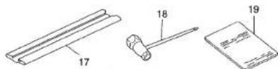
| Included Accessories | Blade case, combination box spanner |
Frequently Asked Questions - TCH 22EBP2 Tanaka
User questions about TCH 22EBP2 Tanaka
0 question about this device. Answer the ones you know or ask your own.
Ask a new question about this device
Download the instructions for your Hedge Trimmer in PDF format for free! Find your manual TCH 22EBP2 - Tanaka and take your electronic device back in hand. On this page are published all the documents necessary for the use of your device. TCH 22EBP2 by Tanaka.
USER MANUAL TCH 22EBP2 Tanaka
Some dust created by power sanding, sawing, grinding, drilling, and other construction activities contains chemicals known to the State of California to cause cancer, birth defects or other reproductive harm. Some examples of these chemicals are:
- Lead from lead-based paints,
• Crystalline silica from bricks and cement and other masonry products, and
• Arsenic and chromium from chemically-treated lumber.
Your risk from these exposures varies, depending on how often you do this type of work. To reduce your exposure to these chemicals: work in a well ventilated area, and work with approved safety equipment, such as those dust masks that are specially designed to filter out microscopic particles.
AVERTISSEMENT:
Minato-ku, Tokyo 108-6020, Japan
Distributed by
Hitachi Koki U.S.A., Ltd.
3950 Steve Reynolds Blvd.
Norcross, GA 30093
Hitachi Koki Canada Corp.
450 Export Blvd. Unit B,
Mississauga ON L5S 2A4
301
Code No. E99252861 NA
Printed In China
Tanaka
Designed for operating in USA & Canada only.
When this product is used in areas other than the USA & Canada.
we cannot guarantee the product quality and performance.
Model TCH 22EAP2 (50ST)/TCH 22EBP2 (62ST) Hedge Trimmer
Modelo TCH 22ECP2 (62ST)/TCH 22ECP2 (78ST) Talle-Hales Cortasetos

natural_image
Technical line drawing of a mechanical device with no visible text or symbols
SAFETY INSTRUCTIONS AND INSTRUCTION MANUAL
WARNING
IMPROPER OR UNSAFE use of this power tool can result in death or serious bodily injury!
This manual contains important information about product safety. Please read and understand this manual BEFORE operating the power tool. Please keep this manual available for other users and owners before they use the power tool. This manual should be stored in safe place.
INSTRUCTIONS DE SECURITE ET MODE D'EMPLOI
⚠ AVERTISSEMENT
MEANINGS OF SYMBOLS
NOTE: Some units do not carry them.
| Symbols△WARNINGThe following show symbols used for the machine. Be sure that you understand their meaning before use. | |||
| It is important that you read, fully understand and observe the following safety precautions and warnings. Careless or improper use of the unit may cause serious or fatal injury. | Off/Stop | ||
| Read, understand and follow all warnings and instructions in this manual and on the unit. | Emergency stop | ||
| Always wear eye, head and ear protectors when using this unit. | Fuel and oil mixture | ||
| Choke - Run position (Open) | Hot surface | ||
| Choke - Choked position (Closed) | Before using your machine• Read the manual carefully.• Check that the cutting equipment is correctly assembled and adjusted.• Start the unit and check the carburetor adjustment. See "MAINTENANCE". | ||
| On/Start | |||
Contents
WHAT IS WHAT? 3
WARNINGS AND SAFETY INSTRUCTIONS......4
SPECIFICATIONS 6
OPERATING PROCEDURES....6
MAINTENANCE 8
TROUBLESHOOTING....11
WHAT IS WHAT?
Since this manual covers several models, there may be some difference between these illustrations and your unit. Use the instructions that apply to your unit.
-
Recoll starter
-
Fuel tank
-
Throttle lever lockout
-
Throttle lever
-
Front handle
-
Rear handle
-
Spark plug
-
Hand guard
-
Cutting blade
-
Air cleaner
-
Stop switch
-
Blade guide
-
Gear case
-
Choke lever
-
Lock lever
-
Priming pump
-
Blade case
-
Combi box spanner
-
Handling instructions

TCH22EAP2 (50ST), TCH22EBP2 (62ST)
TCH22ECP2 (62ST), TCH22ECP2 (78ST)
English
WARNINGS AND SAFETY INSTRUCTIONS
Keep for future reference.
THIS HEDGE TRIMMER CAN CAUSE SERIOUS INJURIES. Read the instructions carefully for the correct handling, preparation, maintenance, starting and stopping of the hedge trimmer. Become familiar with all controls and the proper use of the hedge trimmer.
Operator safety
○ Always wear a safety face shield or goggles.
○ Always wear heavy, long pants, boots and gloves. Do not wear loose clothing, jewelry, short pants, sandals or go barefoot. Secure hair so it is above shoulder length.
Do not operate this tool when you are tired, ill or under the influence of alcohol, drugs or medication.
Never let a child or inexperienced person operate the machine.
○ Beware of overhead power lines.
○ Wear hearing protection.
Never start or run the engine inside a closed room or building. Breathing exhaust fumes can kill.
○ Keep handles free of oil and fuel.
○ Keep hands away from cutting equipment.
○ Do not grab or hold the unit by the cutting equipment.
When the unit is turned off, make sure the cutting attachment has stopped before the unit is set down.
When operation is prolonged, take a break from time to time so that you may avoid possible Hand-Arm Vibration Syndrome (HAVS) which is caused by vibration.
If the cutting mechanism strikes any foreign object or the hedge trimmer starts making any unusual noise or vibration, shut off the power source and allow the hedge trimmer to stop. Disconnect the spark plug wire from the spark plug and take the following steps:
• Inspect for damage;
- Check for, and tighten, any loose parts;
- Have any damaged parts replaced or repaired with parts having equivalent specifications.
⚠ WARNING
- Antivibration systems do not guarantee that you will not sustain Hand-Arm Vibration Syndrome or carpal tunnel syndrome.
Therefore, continual and regular users should monitor closely the condition of their hands and fingers. If any symptoms of the above appear, seek medical advice immediately.
- If you are using any medical electric/electronic devices such as a pacemaker, consult your physician as well as the device manufacturer prior to operating any power equipment.
- When a foreign object is caught in the blade, turn off the engine, and remove the foreign object carefully using a plier etc., after the hedge trimmer has been cooled down. Be careful when removing the foreign object, since the blade may move because of the backlash.
Unit/machine safety
☐ Inspect the entire unit/machine before each use. Replace damaged parts. Check for fuel leaks and make sure all fasteners are in place and securely tightened.
○ Replace parts that are cracked, chipped or damaged in any way before using the unit/machine.
- Keep others away when making carburetor adjustments.
○ Use only accessories as recommended for this unit/machine by the manufacturer.
WARNING
Never modify the unit/machine in any way. Do not use your unit/machine for any job except that for which it is intended.
Fuel safety
Mix and pour fuel outdoors and where there are no sparks or flames.
○ Use a container approved for fuel.
Never remove the fuel cap or add fuel with the power source running. Allow engine and exhaust components to cool down before refuelling.
Do not smoke or allow smoking near fuel or the unit/machine or while using the unit/machine.
○ Never refuel indoors.
○ Wipe up all fuel spills before starting engine.
○ Move at least 3 m away from fueling site before starting engine.
○ Stop engine before removing fuel cap.
○ Empty the fuel tank before storing the unit/machine. It is recommended that the fuel be emptied after each use. If fuel is left in the tank, store so fuel will not leak.
English
Store unit/machine and fuel in area where fuel vapors cannot reach sparks or open flames from water heaters, electric motors or switches, furnaces, etc.
WARNING
Fuel is easy to ignite or get explosion or inhale fumes, so that pay special attention when handling or filling fuel.
Cutting safety
○ Do not cut any material other than plant hedge.
☐ Inspect the area to be cut before each use. Remove objects which can be thrown or become entangled.
○ For respiratory protection, wear an aerosol protection mask when cutting the grass after insecticide is scattered.
Keep others including children, animals, bystanders and helpers outside the 15 m hazard zone. Stop the engine immediately if you are approached.
○ Hold the unit/machine firmly with both hands.
○ Keep firm footing and balance. Do not over-reach.
Keep all parts of your body away from the muffler and cutting attachment when the engine is running.
Keep cutting tool below shoulder level. NEVER operate unit from a ladder, while in a tree or from any unstable support.
When relocating to a new work area, be sure to shut off the machine and ensure that all cutting attachments are stopped.
○ Never place the machine on the ground when running.
○ Always carry a first-aid kit when operating any power equipment.
Never start or run the engine inside a closed room or building and/or near the inflammable liquid. Breathing exhaust fumes can kill.
Maintenance safety
○ Maintain the unil/machine according to recommended procedures.
○ Disconnect the spark plug before performing maintenance except for carburetor adjustments.
○ Keep others away when making carburetor adjustments.
○ Use only genuine Tanaka replacement parts as recommended by the manufacturer.
When the hedge trimmer is stopped for servicing, inspection or storage, shut off the power source, disconnect the spark plug wire from the spark plug and make sure all moving parts have come to a stop.
Allow the hedge trimmer to cool before making any inspection, adjustment, etc.
Transport and storage
○ Carry the unit/machine by hand with the engine stopped and the muffler away from your body.
○ Allow the engine to cool, empty the fuel tank, and secure the unit/machine before storing or transporting in a vehicle.
○ Empty the fuel tank before storing the unit/machine. It is recommended that the fuel be emptied after each use. If fuel is left in the tank, store so fuel will not leak.
○ Store unit/machine out of the reach of children.
○ Clean and maintenance the unit carefully and store it in a dry place.
○ Make sure engine switch is off when transporting or storing.
When transporting in a vehicle or storage, cover blade with blade cover.
If situations occur which are not covered in this manual, take care and use common sense. Contact your Tanaka dealer if you need assistance. Pay special attention to statements preceded by the following words:
⚠ WARNING
Indicates a strong possibility of severe personal injury or loss of life, if instructions are not followed.
CAUTION
Indicates a possibility of personal injury or equipment damage, if instructions are not followed.
NOTE
Helpful information for correct function and use.
CAUTION
Do not disassemble the recoil starter. You may get a possibility of personal injury with recoil spring.
SPECIFICATIONS
| MODEL | TCH22EAP2 (5/ST) | TCH22EBP2 (62ST) | TCH22ECP2 (62ST) | TCH22ECP2 (78ST) |
| Engine Size (cu. in.) | 1.34 (21.1 ml) | |||
| Spark Plug | Champion CJ 6 | |||
| Fuel Tank Capacity (fl. oz) | 10.1 (0.30 l) | |||
| Dry Weight (lbs) | 9.5 (4.3 kg) | 10.4 (4.7 kg) | 11.0 (5.0 kg) | 11.5 (5.2 kg) |
| Overall blade length (in.) | 19.7 (500 mm) | 24.4 (620 mm) | 24.4 (620 mm) | 30.7 (780 mm) |
| Blade type | Double-sided | |||
| Sound pressure level LpA (dB(A)) (ISO 10517) | 84 | |||
| Sound power level Lw measured (dB (A)) (2000/14/EC, ISO 10517) | 102 | |||
| LwA (dB (A)) | 104 | |||
| Vibration level (m/s ^2 )(ISO 10517) | ||||
| Front handle | 7.0 | 9.1 | 2.8 | 2.8 |
| Rear handl | 7.5 | 9.1 | 3.4 | 2.8 |
NOTE
Equivalent noise level/vibration level are calculated as the time-weighted energy total for noise/vibration levels under various working conditions with the following time distribution: ISO 10517....1/5 Idle, 4/5 racing. 2000/14/EC.....only racing.
* All data is subject to change without notice.
OPERATING PROCEDURES
Fuel (Fig. 1)
WARNING
The hedge trimmer is equipped with a two-stroke engine. Always run the engine on fuel, mixed with oil.
Provide good ventilation, when fueling or handling fuel.
Fuel
○ Always use branded 89 octane unleaded gasoline.
Use genuine two-cycle oil or use a mix between 25:1 to 50:1, please consult the oil bottle for the ratio or Tanaka dealer.
○ Only for the state of California at 50:1.
If genuine oil is not available, use an anti-oxidant added quality oil expressly labeled for air-cooled 2-cycle engine use (JASO FC GRADE OIL or ISO EGC GRADE). Do not use BIA or TCW (2-stroke water-cooling type) mixed oil.
Never use multi-grade oil (10W/30) or waste oil.
○ Always mix fuel and oil in a separate clean container.
Always start by filling half the amount of fuel, which is to be used. Then add the whole amount of oil. Mix (shake) the fuel mixture. Add the remaining amount of fuel.
Mix (shake) the fuel-mix thoroughly before filling the fuel tank.
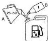
Fig. 1
Fueling
⚠ WARNING (Fig. 2)
● Always shut off the engine before refueling.
● Slowly open the fuel tank (1), when filling up with fuel, so that possible over-pressure disappears.
- Tighten the fuel cap carefully, after fueling.
- Always move the unit at least 10 ft (3 m) from the fueling area before starting.

Fig. 2
Before fueling, clean the tank cap area carefully, to ensure that no dirt falls into the tank. Make sure that the fuel is well mixed by shaking the container, before fueling.
Starting
CAUTION
Before starting, make sure the cutting attachment does not touch anything.
- Set stop switch (2) to ON position (A). (Fig. 3)

Fig. 3
* Push priming pump (4) several times so that fuel flows through the pump or return pipe. (Fig. 4)

Fig. 4
- Set choke lever (5) to CLOSED position (B). (Fig. 5)

Fig. 5
- Pull recoil starter briskly, taking care to keep the handle in your grasp and not allowing it to snap back. (Fig. 6)
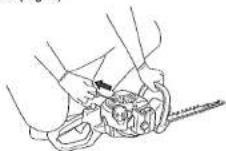
Fig. 6
- When you hear the engine attempts to start, return choke lever to RUN position (open) (C). Then pull recoil starter briskly again.
NOTE
If engine does not start, repeat procedures from 2 to 3.
5. After starting engine, allow the engine about 2-3 minutes to warm up before subjecting it to any load.
Cutting
When cutting, operate engine at full throttle as this maintains proper blade speed. When trimming top of hedge, hold trimmer so blades are between 15 and 30 degrees from a horizontal position and swing trimmer in an arc toward edge of hedge to sweep cuttings off. When trimming sides of hedge, hold blade vertically and swing unit in an arc.
NOTE
○ Multi-position twist handle (Fig. 7)
The rear control handle turns 90 degrees to provide comfortable use while accommodating a variety of cutting angles. The handle allows for five different locking positions. Before attempting to adjust rear handle, make sure the machine is at idle or engine is shut off.
English
☐ The throttle lever cannot be engaged if the handle is not secured (the lock lever is pressed). To rotate the handle; push the lock lever (6) allowing the handle to turn. Rotate the handle to the desired 0°, 45° or 90° locking position and release the lock lever (6) to lock the handle in place.
D: LOCK E: UNLOCK

Fig. 7

Stopping (Fig. 8)
Decrease engine speed, and push stop switch to stop position (F).

Fig. 8
NOTE
If the engine does not stop, it can be forced to stop by rotating the choke lever to the choked position. Before restarting the engine, ask our dealer for repairs.
MAINTENANCE
MAINTENANCE, REPLACEMENT OR REPAIR OF THE EMISSION CONTROL DEVICES AND SYSTEM MAY BE PERFORMED BY ANY NONROAD ENGINE REPAIR ESTABLISHMENT OR INDIVIDUAL.
Carburetor adjustment (Fig. 9)
WARNING
● The cutting attachment may be spinning during carburetor adjustments.
● Never start the engine without the complete cleaner cover. Otherwise the clutch can come loose and cause personal injuries.
In the carburetor, fuel is mixed with air. When the engine is test run at the factory, the carburetor is adjusted. A further adjustment may be required, according to climate and altitude. The carburetor has one adjustment possibility:
T = Idle speed adjustment screw.
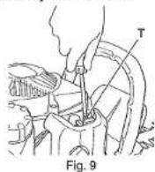
Idle speed adjustment (T)
Check that the air filter is clean. When the idle speed is correct, the cutting attachment will not rotate. If adjustment is required, close (clockwise) the T-screw, with the engine running, until the cutting attachment starts to rotate. Open (counter-clockwise) the screw until the cutting attachment stops. You have reached the correct idle speed when the engine runs smoothly in all positions well below the rpm when the cutting attachment starts to rotate.
If the cutting attachment still rotates after idle speed adjustment, contact Tanaka dealer.
Air filter (Fig. 10)
The air filter must be cleaned from dust and dirt in order to avoid:
○ Carburetor malfunctions.
○ Starting problems.
○ Engine power reduction.
○ Unnecessary wear on the engine parts.
○ Abnormal fuel consumption.
Clean the air filter daily or more often if working in exceptionally dusty areas.
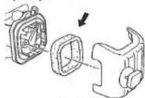
Fig. 10
Cleaning the air filter
Remove the cleaner cover and the filter. Rinse it in warm soap suds. Check that the filter is dry before reassembly. An air filter that has been used for some
English
time cannot be cleaned completely. Therefore, it must regularly be replaced by a new one. A damaged filter must always be replaced.
NOTE
Saturate the element in 2-cycle oil or the equivalent. Squeeze the element to distribute the oil completely and to remove any excess oil.
Spark plug (Fig. 11)
The spark plug condition is influenced by:
○ An incorrect carburetor setting.
○ Wrong fuel mixture (too much oil in the gasoline).
○ A dirty air filter.
○ Hard running conditions (such as cold weather).
These factors cause deposits on the spark plug electrodes, which may result in malfunction and starting difficulties. If the engine is low on power, difficult to start or runs poorly at idling speed, always check the spark plug first. If the spark plug is dirty, clean it and check the electrode gap. Readjust if necessary. The correct gap is 0.024" (0.6 mm). The spark plug should be replaced after about 100 operation hours or earlier if the electrodes are badly eroded.

Fig. 11
NOTE
In some areas, local law requires using a resistor spark plug to suppress ignition signals. If this machine was originally equipped with resistor spark plug, use the same type of spark plug for replacement.
Lubricating the blade (Fig. 12)
During trimming, sap adhering to the blade edge will increase load.
Use machine oil (or bicycle oil or the like) to lubricate the blade and wipe the blade with a cloth. To prevent the blade from rusting, be sure to lubricate the blade after use and when it will not be used for an extended period of time before placing it in the blade case.

Fig. 12
Gear case (Fig. 13)
Apply a good quality lithium based grease through the grease fitting until a small amount comes out between the cutting blades and the gear case. Lubricate the grease from the grease nipple (indicated by an arrow) next to the gear case using a commercially available cartridge grease gun.
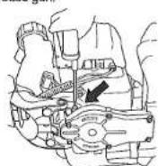
Fig. 13
NOTE
Lubrication should be applied 3g at 20 hour intervals and more frequently with heavy use.
Fuel filter (Fig. 14)
Remove the fuel filter from the fuel tank and thoroughly wash it in solvent. After that, push the filter into the tank completely.

Fig. 14
NOTE
If the filter is hard due to dust and dirt, replace it.
English
Cleaning the cylinder fins (Fig. 15)
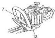
When leaves get caught between cylinder fins (7), the engine may overheat, resulting in lower output. To avoid this, always keep cylinder fins and cylinder cover clean.
Every 100 operating hours, or once a year (more often if conditions require), clean fins and external surfaces of engine of dust, dirt and oil deposits which can contribute to improper cooling.

natural_image
Technical line drawing of a mechanical assembly with components and fasteners (no text or labels)Fig. 15
Cleaning the muffler (Fig. 16)
Remove the muffler and spark arrestor (if so equipped), and clean out any excess carbon from the exhaust port or muffler inlet every 100 hours of operation.
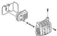
Fig. 16
For long-term storage
Drain all fuel from the fuel tank. Start and let engine run until it stops. Repair any damage which has resulted from use. Clean the unit with a clean rag, or high pressure air hose. Put a few drops of two-cycle engine oil into the cylinder through the spark plug hole, and spin the engine over several times to distribute oil. Cover the unit and store it in a dry area.
Maintenance schedule
Below you will find some general maintenance instructions. For further information please contact your Tanaka dealer.
Daily maintenance
○ Clean the exterior of the hedge trimmer.
○ Check the blade guide for damage or cracks.
Change the guard in case of impacts or cracks.
○ Check that the blade is sharp, and without cracks.
- Check that the blade nut is sufficiently tightened.
- Make sure that the blade blunt guard is undamaged and that it can be securely fitted.
○ Check that nuts and screws are sufficiently tightened.
Weekly maintenance
○ Check the starter, especially cord and return spring.
○ Clean the exterior of the spark plug.
○ Remove it and check the electrode gap. Adjust it
to 0.024" (0.6 mm), or change the spark plug.
○ Clean the cooling fins on the cylinder and check that the inclute of the stator is not clogged.
that the air intake at the starter is not c. Check gas case is filled with grease
- Check gear case is filled with grease.
- Clean the air filter.
- Clean the all filter.
Monthly maintenance
○ Rinse the fuel tank with gasoline.
○ Clean the exterior of the carburetor and the space around it.
○ Clean the fan and the space around it.
TROUBLESHOOTING
Use the inspections in the table below if the tool does not operate normally. If this does not remedy the problem, consult your dealer or the Tanaka dealer.
| Symptom | Possible cause | Remedy | |
| Tool | Does not operate. | Foreign matter is lodged in the blade. | When there is foreign matter in the blade, use a pair of tongs or similar tool to remove it.Take great care since the tool may start operating when the foreign matter has been removed.Sap or rust may also prevent the blade from operating. Use a wire brush or similar tool to remove sap or rust. |
| The tool does not trim well. | The blade stopped because it was used to cut a branch whose width exceeded the blade's cutting capacity.NOTEWork that will repeatedly cause the blade to stop will eventually damage the tool. | Some garden trees have wood that is very hard and may be beyond the capacity of the tool even if it is of a width that is within normal capacity. Use a pair of pruning shear to remove thick branches before starting work.An oblique cut may also exceed the capacity of the tool since the length of the cut increases. Be sure to trim thick branches |
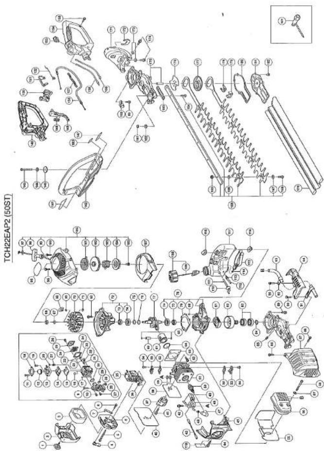
34
TCH22EAP2 (50ST)
| Item No. | Part Name | QTY |
| 1 | COVER FIXING BOLT COMP. | 1 |
| 2 | CLEANER COVER | 1 |
| 3 | CLEANER SPONGE | 1 |
| 4 | CHOCKE VALVE | 1 |
| 5 | MACHINE SCREW (W/WASHERS) Mx10 | 2 |
| 6 | CLEANER BODY | 1 |
| 7 | CHOKE HANDLE | 1 |
| 8 | TAPPING SCREW (WFLANGE) Dx12 | 1 |
| 9 | THROTTLE ADJUST SCREW (TAS) | 1 |
| 10 | SET SCREW (B) | 3 |
| 11 | SET SCREW (D) | 4 |
| 12 | SYRINGE | 1 |
| 13 | PRIMER BASE | 1 |
| 14 | PUMP GASKET | 1 |
| 15 | PUMP DIAPHRAGM | 1 |
| 16 | STRAWER | 1 |
| 17 | GUIDE PIN ROLLER | 1 |
| 18 | SYRINGKE RETAINER | 1 |
| 19 | SET SCREW (E) | 1 |
| 20 | BALL PLUG RETAINER | 1 |
| 21 | ADJUSTING SCREW (MAIN MIXTURE) | 1 |
| 22 | METERING LEVER SPRING | 1 |
| 23 | PIN | 1 |
| 24 | METERING DIAPHRAGM | 1 |
| 25 | METERING COVER | 1 |
| 26 | SET SCREW (C) | 3 |
| 27 | POST | 1 |
| 28 | ROTOR COVER | 1 |
| 29 | RETAINING RING (E-TYPE) FOR D2.5 SHAFT | 1 |
| 30 | O-RING | 1 |
| 31 | INLET NEEDLE VALVE | 1 |
| 32 | SET SCREW (A) | 1 |
| 33 | METERING LEVER | 1 |
| 34 | METERING GASKET | 1 |
| 35 | CARBURETOR ASSY (INCLUD.3-34) | 1 |
| 36 | LOCK NUT M6 | 1 |
| 37 | CARBURETOR INSULATOR | 1 |
| 38 | INTAKE PACKING | 1 |
| 39 | GLASS WASHER | 4 |
| 40 | CARBURETOR PACKING | 1 |
| 41 | SEAL LOCK HEX. SOCKET BOLT (WWASHERS) Mx25 | 2 |
| 42 | HEX. SOCKET HD. BOLT (WWASHERS) Mx18 | 2 |
| 43 | CORD | 1 |
| 44 | SEAL LOCK HEX. SOCKET HD. BOLT M4x12 | 1 |
| 45 | CYLINDER COVER | 1 |
| 46 | METAL OF PLUG CAP (60) (B) | 1 |
| 47 | PLUG CAP | 1 |
| 48 | CORD INSULATION TUBE | 1 |
| 49 | IGNITION COIL | 1 |
| 50 | SPARK PLUG | 1 |
| 51 | CYLINDER | 1 |
| 52 | COVER PACKING | 2 |
| 53 | INTAKE COVER (A) | 1 |
| 54 | SEAL LOCK SCREW M4x10 | 4 |
| 55 | HEAT PROTECTION PANEL | 1 |
| 56 | MUFFER | 1 |
| 57 | BOLT WASHER M6 | 2 |
| Item No. | Part Name | Q'TY |
| 58 | HEX, SOCKET HD, BOLT MEX55 | 2 |
| 59 | INTAKE COVER (B) | 1 |
| 60 | PISTON PIN | 1 |
| 61 | PISTON | 1 |
| 62 | HEX, SOCKET HD, BOLT (WISP WASHER) M5×16 | 8 |
| 63 | CYLINDER PACKING | 1 |
| 64 | PISTON RING | 1 |
| 65 | CIR CUP | 2 |
| 66 | FLYWHEEL NUT M7 | 1 |
| 67 | BOLT WASHER D7 | 1 |
| 68 | STARTER FAWL | 2 |
| 69 | STARTER FAWL SPRING | 2 |
| 70 | MAGNETO ROTOR | 1 |
| 71 | RETAINING RING D4 | 2 |
| 72 | CRANK CASE (B), ASS'Y (INCLUD.73/74) | 1 |
| 73 | OIL SEAL T9 12227 | 2 |
| 74 | BALL BEAFING 6001G3 | 2 |
| 75 | SHIM T0.2 | 1 |
| 76 | SHIM T0.3 | 1 |
| 77 | CRANK SHAFT | 1 |
| 78 | CRANK CASE (A) ASS'Y (INCLUD.73/74,80) | 1 |
| 79 | CRANK CASE PACKING | 1 |
| 80 | KNOCK PIN 4x12 | 2 |
| 81 | CLUTCH ASSY (B) | 1 |
| 82 | CLUTCH DRUM | 1 |
| 83 | BALL BEAFING 6002ZC3 | 2 |
| 84 | RETAINING RING FOR D15 SHAFT | 1 |
| 85 | GREASE NIPPLE COMP. | 1 |
| 86 | TAPPING SCREW (WISP AWERS) M5×20 | 1 |
| 87 | MUFFLER PROTECTOR | 1 |
| 88 | MACHINE SCREW (WISP WASHERS) M5×16 | 1 |
| 89 | HEX, HOLE BOLT 6x16/S | 4 |
| 90 | HEX, SOCKET HD, BOLT (WBUTTON) M5×20 | 2 |
| 91 | FIXATION PLATE (A) | 1 |
| 92 | FIXATION PLATE (B) | 1 |
| 93 | TAIL PIPE (A) | 1 |
| 94 | EXHAUST COVER | 1 |
| 95 | LABEL | 1 |
| 96 | TAPPING SCREW D4.5x16 | 1 |
| 97 | PLATE | 1 |
| 98 | STARTER KNOB | 1 |
| 99 | STARTER ROPE | 1 |
| 100 | HEX, SOCKET HD, BOLT (WBUTTON) M5×20 | 3 |
| 101 | RECOIL SPRING | 1 |
| 102 | STARTER ROPE REEL | 1 |
| 103 | DAMPER SPRING | 1 |
| 104 | CAM PLATE | 1 |
| 105 | SCT SCREW | 1 |
| 106 | RECOIL STARTER ASSY (INCLUD.97/91,101-105) | 1 |
| 107 | AIR DEFLECTOR | 1 |
| 108 | FUEL TANK CAP ASSY (INCLUD.109) | 1 |
| 109 | TANK CAP CHAIN | 1 |
| 110 | FUEL GROMMET | 1 |
| 111 | FUEL PIPE | 1 |
| 112 | FUEL PIPE (PINK) | 1 |
| 113 | RETURN GROMMET | 1 |
| Part No. | Part Name | QTY |
| 114 | CLIP | 1 |
| 115 | PUMP FILTER | 1 |
| 116 | CUSHION RUBBER | 4 |
| 117 | TANK | 1 |
| 118 | CAUTION LABEL | 1 |
| 141 | NAME PLATE | 1 |
| 142 | HANDLE | 1 |
| 143 | SEAL LOCK HEX, SOCKET HD, BOLT M5x40 | 2 |
| 144 | SPRING WASHER M5 | 2 |
| 145 | SPRAKE AXIS WASHER | 2 |
| 146 | HANDLE A | 1 |
| 147 | CAUTION LABEL | 1 |
| 148 | SPRING (A) | 1 |
| 149 | LOCKLEVER | 1 |
| 150 | THROTTLE LEVER | 1 |
| 151 | TRIGGER LOCKOUT | 1 |
| 152 | THROTTLE LEVER SPRING | 1 |
| 153 | STOP SWITCH | 1 |
| 154 | HANDLE B | 1 |
| 155 | TAPPING SCREW (W/FLANGE) D4x18 | 4 |
| 156 | THROTTLE WIRE | 1 |
| 157 | PROTECTION TUBE | 1 |
| 158 | STOP SWITCH CORD | 1 |
| 159 | STOP SWITCH CORD (B) | 1 |
| 160 | FIXATION PLATE (B) | 1 |
| 161 | NYLON NUT M5 | 2 |
| 162 | SMALL WASHER 5 | 2 |
| 163 | SPACER | 1 |
| 164 | HEX, SOCKET HD, BOLT (WR BUTTON) M5x25 | 2 |
| 165 | U-NUT M5 | 5 |
| 166 | WASHER (B) | 5 |
| 167 | WASHER M7 | 5 |
| 168 | SHOULDER BUTTON BOLT M5x25 | 5 |
| 169 | BLADE ASSY (INCLUD 164-168) | 1 |
| 170 | BLADE CASE (A) | 1 |
| 171 | HANDLE BRACKET | 1 |
| 172 | CLIP | 1 |
| 173 | BOLT WASHER D5 | 3 |
| 174 | SEAL LOCK HEX, SOCKET BOLT (WW/ASHERS) M5x16 | 3 |
| 175 | GEAR CASE (A) ASSY (INCLUD 178) | 1 |
| 176 | GUIDE PLATE (C) | 1 |
| 177 | GEAR 2 | 1 |
| 178 | GUIDE PLATE (A) | 1 |
| 179 | FELT PACKING (A) | 1 |
| 180 | GEAR CASE PACKING | 1 |
| 181 | GEAR CASE COVER | 1 |
| 182 | HEX, SOCKET HD, BOLT (WSP/WASHER) M5x12 | 6 |
| 183 | START LABEL (B) | 1 |
| 501 | BOX WRENCH 10/19MM | 1 |
TANAKA
EPA / CALIFORNIA EMISSIONS CONTROL
WARRANTY STATEMENT
THE US EPA, THE CALIFORNIA AND RESOURCES BOARD AND ITEMS NEW U.S.A., LTD. AVE PLEASED TO EXPLAIN THE EXHAUST AND EMPARATIVE EMISSION CONTROL. SYSTEM WARRANTY ON YOUR ROOT AND LATER SMALL OFF ROAD HAND MELD ENGINE. NEW EQUIPMENT THAT USE SMALL OFF ROAD ENCHES MUST BE DISIGNED, INLET AND EQUIPPED TO MEET STRINENT FEDERAL AND STATE ANTI SHOCK STANDARDS. HISSE KIMU S.A., LTD. MUST HAVE RAIL THE EMISSION CONTROL SYSTEM ON YOUR ROOT OFF ROAD HAND MELD ENGINE FOR THE PERIODS OF TIME LISTED BELOW PREPARED THERE HAS BEEN NO ABUSE, NOBJECT ON OPROPERT INFRASTRUCTURE OF SMALL OFF ROAD ENGINE.
YOUR EMISSION CONTROL SYSTEM MAY INCLUDE PARTS SUCH AS: CASH RETIONS OF FUEL, INJETO ON SYSTEM, SWITCH SYSTEM, CATALYTE CONVENTORS, FOIL, TUNKE, VANE, FILTERS, CLAMPS, CONNECTORS, AND OTHER ASSOCIATED COMPONENTS. ALSO INCLUDED MAY BE HOOD, BOLTS, CONNECTORS, SENATORS, AND OTHER EMISSION-RELATED ASSEMBLIES.
WHERE A WARRANTY CONDITION EXISTS, HEATEN XIKHUI S.A., LTD. WILL REPAIR YOUR SMALL EFP ROAD HAND HAND ENGINE AT NO COST TO YOU INCLUDING DIAGNERS, PARTS AND LABEL
MANUFACTURE'S WARRANTY COVERAGE
THE EMISSIONS CONTROL SYSTEM IS WARRANTED FOR TWO YEARS. IF ANY EMISSION RELATED PART BY YOUR ENGINE IS DEFECTIVE, THE PART WILL BE REPAINED OR REPLACED BY NIACH KIDU U.S.A., LTD.
OWNER'S WARRANTY RESPONSIBLES
AS THE SMALL OFF ROAD HAND HELD ENGINE OWNER, YOU ARE RESPONSIBLE FOR THE PERFORMANCE OF THE MOUNTED MAINTENANCE LISTED IN YOUR OWNERS' MANUAL. HARRI KIRD U.S.A., LTD. RECOMMENDED THAT YOUTRETM ALL RECEIPTS COVERING MAINTENANCE IN YOUR SMALL OFF HAND HAB O' HELD ENGINE, BUT WITHOUT WARRANTY SOULY FOR THE LACK OF RECEIPTS ON PER YOUR FAILURE TO ENSHURE THE PERFORMANCE OF ALL SCHEDULED MAINTENANCE.
AS THE SMALL OFF ROAD HAND HELD CAUGH OWNER, YOU SHOULD HOWEVER BE AVAILABLE THAT HAS/SH AND U.S.A., LTD. MAY ONLY YOU WARRANTY COVERAGE IF YOUR SMALL OFF ROAD HAND HELD ENGINE OR A PART HAS FAILED DUE TO ABUSE, REFECT, IMPROVER MAINTENANCE OR UNAPPROVED MODIFICATIONS.
YOU ARE RESPONSIBLE FOR PRESENTING YOUR LAIN AND SARDEN EQUIPMENT ENGINE TO A BITACHI WHO U.S.A., LTD. SERVICE CENTER AS SUCH AS A PROBLEM EXISTS. THE WARRANTY REPAIRS SHOULD BE COMPLETED IN A REASONABLE AMOUNT OF TIME, NOT TO EXCEED 30 DAYS.
IF YOU HAVE ANY QUESTIONS REPAFISHED YOUR WARRANTY RIGHTS AND RESPONSIBILITY, YOU SHOULD CONTACT A NOTICE BOX U.S.A., LTD. CUSTOMER SERVICE REPRESENTATIVE AT (888) 492-5052.
DISECTS WARRANTY REQUIREMENTS:
(3) THE WARRANTY PERIOD SEARS ON THE DATE THE ENGINE OR EQUIPMENT IS DELIVERED TO AN ULTIMATE PURCHASER.
(3) GENERAL EMISSIONS WARRANTY COVERAGE. HITACHI KOD U.S.A., LTD. MUST WARRANT TO THE ULTIMATE PURCHASER AND EACH SUBNSPECT OWNER THAT THE INFOD OR HOUSTAWAY IS:
- DESIGNED, GUILT, AND EQUIPPED SO AS TO CONFORM WITH ALL APPLICABLE REGULATING AS ADMITTED BY THE AIR RESOURCES BOARD; AND
- FILED FROM DEFECTS IN MATERIALS AND WORKMANSHIP THAT CAUSES THE FAILURE OF A WARRIANTED PAINT FOR A PERIOD OF TWO YEARS.
(4) THE WARRANTY ON EMISSION RELATED PARTS WILL BE INTERPRETED AS FOLLOWS:
-
ANY WARRANTED PART THAT IS NOT SCHEDULED FOR REPLACEMENT AS REQUIRED MAINTENANCE IN THE WRITTEN INSTRUCTIONS REPLISHED BY SUBSECTION (C) MUST BE WARRANTED FOR THE WARRANTY PATTERN DATED IN SUBSECTION (S)(2): IF ANY SUCH PART FAILS DURING THE PATTERN OF WARRANTY COVERAGE, IT MUST BE REPAINED OR REPLAINED BY THE MANUFACTURER RECORDING TO SUBSECTION (D) BELOW ANY SUCH PART REPAINED OR REPLACED UNDER THE WARRANTY MUST BE WARRANTED FOR THE REMAINING WARRANTY PERAR.
-
ANY WARRANTED PART THAT IS SCHEDULES FOR REGULAR INSPECTION IN THE WRITTEN ENSEMBLICING REQUIRED BY SUBSCRIPTION (4) MUST BE WARRANTED FOR THE WARRANTY PERIOD DEFINED IN SUBSECTION (3)(1). A STATEMENT IS SUCH WRITTEN INSTRUCTIONS TO THE EFFECT OF "REPAIR OR REPLACE AS NECESSARY" WILL NOT REDUCE THE PERIOD OF WARRANTY OUTRAGE, ANY SUCH PART REPAISED OR REPLACED UNDER WARRANTY MUST BE WARRANTED FOR THE WARRANTY WARRANTY PERIOD.
-
ANY WARRANTED PART THAT IS SCHEDULED FOR REPLACEMENT AS REQUIRED MAINTENANCE IN THE WRITTEN INSTRUCTIONS REQUIRED BY SUBSECTION (A) MUST BE WARRANTED FOR THE PERIOD OF TWO PRIOR TO THE FIRST SCHEDULED REPLACEMENT POINT FOR THAT PART IF THE PART TAILS PRIOR TO THE FIRST SCHEDULED REPLACEMENT, THE PART MUST BE REPAIRED OR REPLATED BY THE ENGINE MANUFACTER ACCORDING TO SUBSECTION (B) BELOW ANY SUCH PART REPAIRED OR REPLACED INDIUR WARRANTY MUST BE WARRANTED FOR THE REMAINDER OF THE PERIOD PRIOR TO THE FIRST SCHEDULED REPLACEMENT POINT FOR THE PART.
-
REPAIR OR REPLACEMENT OF ANY WARRANTED PART UNDER THE WARRANTY MUST BE PERFORMED AT NO CHARGE TO THE OTHER AT A WARRANTY POSITION.
-
NOTWITHSTANDING THE PROVISION OF SUBSECTION (10) ABOVE, WARRANTY SERVICES OR REPAIRS MUST BE PROVIDED AT ALL
-
THE OWNER MUST NOT BE CHARGED FOR DIAGNOSTIC LAVOR THAT LEADS TO THE DETERMINATION THAT A WARRANTED PART IS IN FACTS.
-
THE MANUFACTURER IS LIABLE FOR DAMAGES TO OTHER ENGINE COMPONENTS PROXIMATELY CAUSED BY A FAILURE UNDER WARRANTY OF ANY WARRANTED PART
-
THOACHUT THE EMISSIONS WARRANTY PERIOD DEFINED IN SUBSECTION (R)(2), THE MANUFACTURER MUST MOUNTAIN A SUPPLY OF WARRANTED PARTS SUFFICIENT TO INIT THE EXPECTED DEMAND FOR SUCH PARTS
-
ANY REPLACEMENT PUT MAY BE USED IN THE PERFORMANCE OF ANY WARRANTY MAINTENANCE OR REPAIRS AND MUST BE PROVIDED WITHOUT CHANGE TO THE OWNER. SUCH USE WILL NOT REDUCE THE WARRANTY OBLIGATIONS OF THE MANUFACTURER.
-
ADO-ON OR MODIFIED PARTS THAT ARE NOT EXEMPTED BY THE AIR RESOURCES BOARD MAY NOT BE USED. THE USE OF ANY NON-EXEMPTED ADO-ON OR MODIFIED PARTS WILL BE GROUNDS FOR DISALLIVING A WARRANTY CLINN. THE MAHABRINDER WILL NOT BE
LIMBLE TO WARRANT FAILURES OF WARRIYETO PARTS CAUSED BY THE USE OF A NON-EXISTPTED ADD-IN OR INSURED PART. 11. THE MANUFACTURER ISSUBING THE WARRANTY SHALL PROVIDE ANY DOCUMENTS THAT DESCRIBES THAT MANUFACTURER'S WARRANTY
PROCEDURES OR POLICIES WITHEN FIVE WORKING DAYS OF REQUEST BY THE AIR RESOURCES BOARD.
(4) EMISSIONWARRANTY PARTS LIST
- FUEL, METERING SYSTEM
-
CARRIER FOR AND INTERNAL PARTS AND JEW PRESSURE REGULATOR OR FUEL SWITCH SYSTEM
-
AIR/FUEL RATIO FEEDBACK AND CONTROL SYSTEM.
-
COLD STAR
-
FUEL TANK
-
AIR INJECTION SYSTEM
-
CONTROLLED HOT AIR INTAKE SWITCH.
-
INTAKE MANSHOLD
-
线性滤
-
IGNITION SYSTEM
-
SPARK PLUGS.
-
MACHATO DE OLATEBANIC GUSTOPE SYSTEM
-
SPARK ADVANCE/RETARIO SYSTEM.
-
EXHAUST GAS RECONVATION (EQR) SYSTEM
-
EGF VAVE BUNT, AND
- FOR RATE FEEDBACK
A. AIR INJECTION SYSTEM
- AIR PUMP OR PULSE VALVE.
-
STAFFS ASSOCIATION INCREASE
-
MELINDA EFFECTIVE DISTRIBUTION OF F
-
DISTRIBUTION HASFOLD.
-
CATALYST OR THERMAL REACTION SYSTEM
-
CAINISTIC CONVERTER
-
EQUISILE REDUCTOR.
-
EXHAUST NANFOLD.
-
FARRICULATE CONTROLS
-
TRAPS, FILTERS, PRESCRITORS, AND ANY OTHER DEVICE USED TO CAPTURE FABRICULATE EMISSIONS.
-
MISCELLANEOUS REDES USED IN ABOVE SYSTEMS.
-
ELECTRIC CONSENS
-
VACOCHUM TEMPERATURE AND TIME SENSITIVE VALUATION SWITCHES.
-
HOES, BELTS, CONNECTORS, AND ASSEMBLIES.
WHICH KONJ U.S.A., LTD. WILL PURPOSE WITH EACH NEW ENGINE WRITTEN INSTRUCTIONS FOR THE MAINTENANCE AND USE OF THE ENGINE BY THE NEW OWNER.
1 EPA / CONTROL DE EMISIONES EN CALIFORNIA
(2) The authors of the Department of Health and Environment are based on the use of a single health plan.
- AVERTISSEMENT:
- Tanaka
- SAFETY INSTRUCTIONS AND INSTRUCTION MANUAL
- WARNING
- INSTRUCTIONS DE SECURITE ET MODE D'EMPLOI
- ⚠ AVERTISSEMENT
- Contents
- WHAT IS WHAT?
- English
- WARNINGS AND SAFETY INSTRUCTIONS
- Keep for future reference.
- Operator safety
- ⚠ WARNING
- Unit/machine safety
- Fuel safety
- Cutting safety
- Maintenance safety
- Transport and storage
- CAUTION
- NOTE
- OPERATING PROCEDURES
- Fuel (Fig. 1)
- Fuel
- Fueling
- ⚠ WARNING (Fig. 2)
- Starting
- Cutting
- MAINTENANCE
- Carburetor adjustment (Fig. 9)
- Air filter (Fig. 10)
- Cleaning the air filter
- Spark plug (Fig. 11)
- Lubricating the blade (Fig. 12)
- Gear case (Fig. 13)
- Fuel filter (Fig. 14)
- Cleaning the cylinder fins (Fig. 15)
- Cleaning the muffler (Fig. 16)
- For long-term storage
- Maintenance schedule
- Daily maintenance
- Weekly maintenance
- - Clean the all filter.
- Monthly maintenance
- EPA / CALIFORNIA EMISSIONS CONTROL
- WARRANTY STATEMENT
- EPA / CONTROL DE EMISIONES EN CALIFORNIA
Brand : Tanaka
Model : TCH 22EBP2
Category : Hedge Trimmer