
SUFL300M - TV Stand SONY - Free user manual and instructions
Find the device manual for free SUFL300M SONY in PDF.
| Product Type | TV Support |
| Brand | Sony |
| Model | SU-FL300M |
| Dimensions (W × D × H) | 1035 × 503 × 120 mm |
| Net weight | 35 kg |
| Main material | Tempered glass and steel |
| Color | Black |
| Maximum load of the glass shelf | 30 kg |
| Compatible TV models | Specific Sony LCD models (see manual) |
| Rotation | Possible for some models (swiveling) |
| Main functions | TV stand with glass shelf, cable management, hooks for Home Theatre center speaker |
| Maintenance and cleaning | Soft dry cloth; stubborn stains with neutral soap, then wipe |
| Safety | Mandatory wall anchoring via anchor bolts and support strap; do not exceed the shelf load; do not climb or lean |
| Installation | Reserved for an authorized Sony technician; requires at least two people |
| Included accessories | Support strap, anchor bolts, screws, sleeves, caps, paper template, adhesive tape |
| Repairability | Not repairable by user; contact Sony service |
| Warranty | Refer to Sony general terms and conditions |
Frequently Asked Questions - SUFL300M SONY
User questions about SUFL300M SONY
0 question about this device. Answer the ones you know or ask your own.
Ask a new question about this device
Download the instructions for your TV Stand in PDF format for free! Find your manual SUFL300M - SONY and take your electronic device back in hand. On this page are published all the documents necessary for the use of your device. SUFL300M by SONY.
USER MANUAL SUFL300M SONY
Thank you for purchasing this product.
For customers
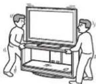
This product should only be installed by qualified Sony service representatives, as it requires two or more people, special care, safety, and technique.
WARNING
If the safety precautions are not observed or the product is used incorrectly, it may result in serious injury or fire.
This instruction manual shows the correct handling of the product and important precautions necessary to prevent accidents. Be sure to read this manual thoroughly and use the product correctly. Keep this manual available for future reference.
For Sony dealers
Installation of a TV requires two or more people, special care and technique. When installing a TV, refer to this manual carefully. Sony is not liable for any accidents or damages caused by incorrect installation or handling. Please give this manual to the customer after installation.
On Safety
Products by Sony are designed with safety in mind. Incorrect use may result in a serious injury through fire, electric shock, the product toppling over, or the product dropping. Be sure to observe the precautions for safety to prevent such accidents.
CAUTION
Specified products
The following products are subject to change without notice. Certain models may be out of stock or discontinued, or may not be available in certain regions.
| LCD Color TV | ||
| SU-FL300M | KDL-46W3500 | KDL-40D2600 |
| KDL-46W3100 | KLV-40W300A | |
| KDL-46W3000 | KLV-40V300A | |
| KDL-46V3100 | KLV-40D300A | |
| KDL-46V3000 | KDL-37S3100 | |
| KDL-46VL130 | KLV-37S310A | |
| KDL-46S3000 | KDL-32XBR4 | |
| KDL-46D3550 | KDL-32V3100 | |
| KDL-46D3500 | KDL-32T3000 | |
| KDL-46D3100 | KDL-32T2800 | |
| KDL-46D3010 | KDL-32T2600 | |
| KDL-46D3000 | KDL-32S3100 | |
| KLV-46W300A | KDL-32S3000 | |
| KLV-46V300A | KDL-32SL130 | |
| KLV-46D300A | KDL-32D3100 | |
| KDL-40W3500 | KDL-32D3010 | |
| KDL-40W3100 | KDL-32D3000 | |
| KDL-40W3000 | KDL-32D2810 | |
| KDL-40V3100 | KDL-32D2710 | |
| KDL-40V3000 | KDL-32D2600 | |
| KDL-40VL130 | KLV-32V300A | |
| KDL-40T3000 | KLV-32S310A | |
| KDL-40T2800 | KLV-32D300A | |
| KDL-40T2600 | ||
| KDL-40S3000 | ||
| KDL-40SL130 | ||
| KDL-40D3550 | ||
| KDL-40D3500 | ||
| KDL-40D3100 | ||
| KDL-40D3010 | ||
| KDL-40D3000 | ||
| KDL-40D2810 | ||
| KDL-40D2710 | ||
| SU-FL300L | KDL-52W3000 | |
| KDL-52WL130 | ||
| KDL-46W3000 | ||
| KDL-46V3000 | ||
| KDL-46VL130 | ||
| KDL-46S3000 | ||
This TV Stand is designed for use with the products specified above. For other TVs, refer to their operating instructions to verify that the TV Stand can be used.
Some TVs are supplied with a leaflet explaining how to install the TV Stand.
WARNING
If the following precautions are not observed, serious injury or death can result through fire, electric shock, or the product toppling over.
Products should only be installed by qualified Sony service representatives.
The TV and the TV Stand are very heavy; installation by non-qualified persons could result in serious injury.
Be sure to take measures to prevent the TV Stand from toppling over.
If you fail to do so, the TV may topple over and cause injury. Anchor the TV to a wall, etc., to prevent toppling over.
Be sure to install the TV Stand on a solid and flat floor.
Do not install the TV Stand so that it leans in one direction. If you do so, the TV Stand may topple over or the TV may fall. This may cause injury or damage.
If you install the TV Stand on a soft surface such as a mat or a carpet, lay a board over the designated location beforehand.
Do not use a cracked TV Stand.
Do not use the TV Stand if it has sustained any cracks. The glass may break and cause the TV to topple over, which could cause serious injury or damage. Cracked TV St
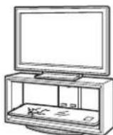
Do not lean on or hang from the TV.
The TV Stand may topple over, or the TV may fall and cause serious injury or death.
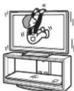
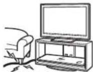
Do not allow children to climb on the TV Stand or crawl between the shelves.
If children climb on the TV Stand or get between the shelves, serious injury or death can result if the glass breaks or the TV Stand and the TV topples over.
Do not step on the TV Stand.
You may fall, or break the glass and cause injury.
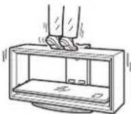
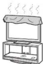
Do not cover the ventilation holes of the TV.
If you cover the ventilation holes (with a cloth, etc.), heat may build up inside and cause fire.
Do not allow the AC power cord or the connecting cable to be pinched.
- Do not allow the AC power cord or the connecting cable to be pinched when you install the TV on the TV Stand. If the AC power cord or the connecting cable is damaged, this may result in fire or electric shock.
- Do not step on the AC power cord or the connecting cable when you carry the TV Stand. The AC power cord or the connecting cable may be damaged, and this may result in fire or electric shock.
Do not move the TV Stand with the TV attached or with connected equipment inside.
If you move the TV Stand with the TV attached, it may hurt your back, or the TV Stand may topple over and cause serious injury. Also, any connected equipment within may fall and cause the glass shelf to break or other property damage.
CAUTION
If the following precautions are not observed, injury or property damage may occur.
Do not install any equipment other than the specified product.
- This TV Stand is designed for use with the specified product only. If you install equipment other than specified, it may fall or break, and cause injury.
- Do not place objects such as vases, pottery, etc., on the TV Stand.
- Do not modify the TV Stand.
- Do not place anything hot directly on the TV Stand. The heat may cause discoloration or deformation of the TV Stand.
- Do not place anything directly on the TV Stand that may damage the glass.
Be sure to secure the TV.
Secure the TV to the TV Stand using the supplied anchor attachments. If the TV is not installed securely, it may fall, or the TV Stand may topple over, and cause injury.
Do not apply weight to the glass or subject it to any kind of impact.
Do not apply weight to the TV Stand with your hand when installing the TV. Do not hit the TV Stand with hard objects, such as a screwdriver, etc. The glass may break and cause injury.
When carrying the TV Stand
Trying to move the TV Stand alone, or without following the proper procedures, may cause injury. To avoid this, be sure to follow the advice given below.
- Be sure that two or more persons carry the TV Stand, and only after removing the TV, connected equipment and glass shelves.
- Do not drag the TV Stand. The base parts of the TV Stand may come off and damage the floor.
- Be careful not to allow your hands or feet to be pinched under the Base Board.
- Do not grab the glass shelf when carrying the TV Stand.
Do not subject the glass to excessive shock.
This TV Stand is made of tempered glass, but care should be taken.
If the glass breaks, glass fragments could cause injury, so observe the precautions below.
- Do not hit the glass or drop sharp-pointed objects on the glass. Avoid excessive shock.
- Do not scratch or poke the glass with sharp-pointed objects.
- Do not let hard objects such as a vacuum cleaner hit the edges of the glass.
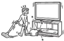
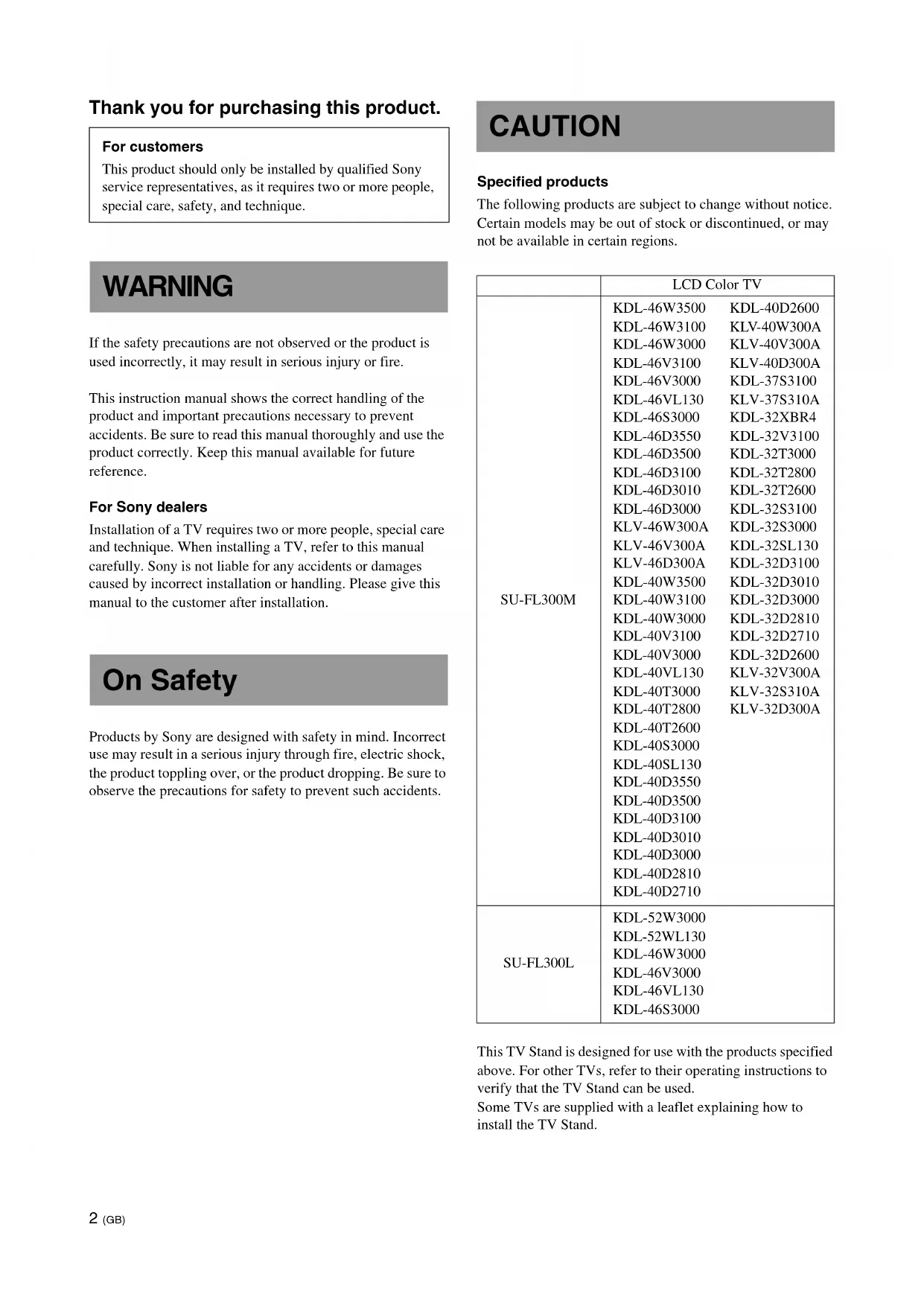
natural_image
Illustration of a person using a vacuum cleaner to clean the TV (no text or symbols present)
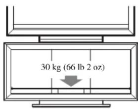
Note on carrying capacity
Do not place any equipment which exceeds the maximum weight for each shelf as indicated in the illustration.
Otherwise, the shelves may break.
Notes on installation
- When assembling, lay the packing materials on the floor to avoid damage to the floor.
- Install the TV Stand on a solid and flat floor. Do not allow the TV Stand to be installed at an angle or incline. To avoid this, observe the following precautions.
- Do not install the TV Stand in a place subject to direct sunlight or near a heater.
- Do not install the TV Stand in a hot or humid place, or outdoors.
Note on use
To keep the TV Stand clean, occasionally wipe it with a dry soft cloth. Stubborn stains may be removed by wiping with a cloth slightly dampened with mild soap. Be sure to dry the area afterwards with a dry soft cloth. Do not use chemicals, such as thinner or benzine, as they damage the finish of the TV Stand.
To Sony dealers
Be sure to thoroughly read the safety precautions described previously and pay special attention to safety during the installation, maintenance, checking, and repair of this product.
Be sure that two or more persons do the installation work.
Be sure that two or more persons install the TV on the TV Stand. If one person does the installation work alone, this may result in an accident or injury. Be sure to keep children away during the installation.
Be sure to assemble the TV Stand securely following the instructions.
If a screw is not tightened securely, or it has fallen out, it may cause the TV Stand to topple over. This may cause damage or injury.
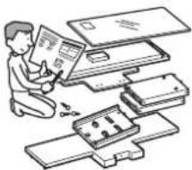
natural_image
Illustration of a person assembling or sorting electronic components (no text or symbols visible)Be careful not to injure your hands or fingers while assembling.
Be careful not to pinch your fingers or hands when assembling the TV Stand and installing the TV.
Be sure to install the TV securely following the instructions.
Tighten the screws securely. If the TV is not installed securely, it may fall and cause injury.
Step 1: Checking the parts
| Name Quantity | |||
| Top Board | 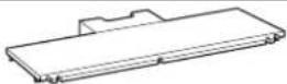 | 1 | |
| Base Board | 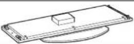 | 1 | |
| Side Pillar (L)*1 |  | 1 | |
| Side Pillar (R)*1 |  | 1 | |
| Rear Pillar |  | 1 | |
| Front Panel |  | 1 | |
| Glass Shelf |  | 1 | |
| Screw (+PWH5 × 25) |  | a*4 | 8 |
| Screw (+K4 × 20) + Sleeve |  | b*4 | 2 |
| Cam-lock screw | 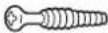 | c*4 | 4 |
| Screw (+P4 × 15) |  | d*4 | 4 |
| Anchor bolt |  | e*4 | 2 |
| Screw cap |  | f*4 | 3 |
| Support belt | 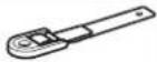 | g*4 | 1 |
| Screw (M6 × 18) | [XSZY] | ||
| Wood screw (M3.8 × 20) | [0W4W] | ||
| Speaker Hook (L) | 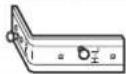 | 1 | |
| Speaker Hook (R) | 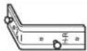 | 1 | |
| Paper template | 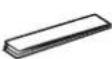 | 4*2 | |
| 3*3 | |||
| Tape | 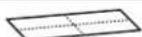 | 1 | |
*1 The illustrations above are for SU-FL300M. This differs from SU-FL300L. For SU-FL300L, there are two cutout parts on the side of the Side Pillar.
*2 For SU-FL300M, four paper templates are provided.
*3 For SU-FL300L, three paper templates are provided.
*4 The parts bags are labeled alphabetically.
Be sure to have a Phillips screwdriver that fits the screws indicated above prior to the assembly.
Step 2: Assembling the TV Stand
WARNING
If you allow the AC power cord to be pinched under or between pieces of equipment, this may result in a short circuit or an electric shock. If you stumble over the AC power cord or the connecting cable, the TV Stand may topple over and cause injury.
Decide on the installation location and lay the TV Stand down before installing the TV.
Since the TV is heavy, it is recommended that you decide on the installation location beforehand, and assemble the TV Stand on site.
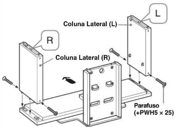
1 Attach the Rear Pillar to the Base Board.
① Tighten the two supplied Cam-lock screws to the Base Board.
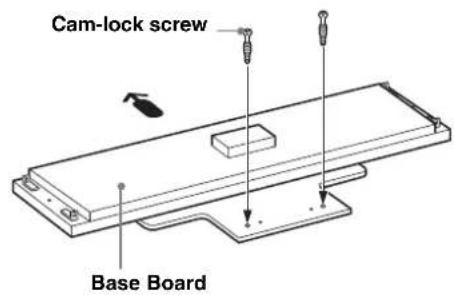

Arrow direction shows front of the TV Stand.
② Attach the Rear Pillar to the Base Board and secure the two Cam-locks with a screwdriver.
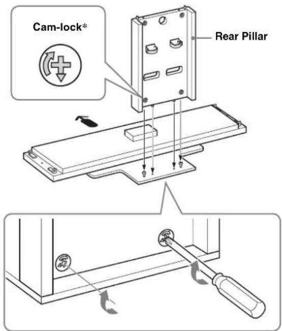
* Before attaching the Rear Pillar, make sure that the mark points downward.
2 Attach the Side Pillars to the Base Board.
Secure the Side Pillars and the Base Board with the four supplied screws (+PWH5 × 25).
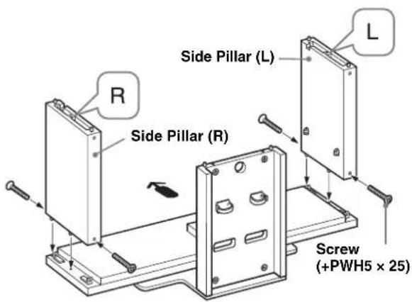
Note
There are differences between the left and right pillars. Be sure to install each pillar on the correct side.
3
Attach the Top Board.
① Tighten the two supplied Cam-lock screws to the Top Board.
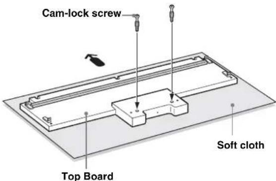
The illustration shown above is SU-FL300M as an example. For SU-FL300L, there are two reinforcing bars on the Top Board.
Note
To prevent damaging the glossy surface of the Top Board, make sure to clean and place a soft cloth on the work surface.
② Align and insert fixing brackets on both sides of the Top Board into the Side Pillars.
③ Secure the Side Pillars with the four supplied screws (+PWH5 × 25). And secure the two remaining Camlocks on the back side of the Rear Pillar.
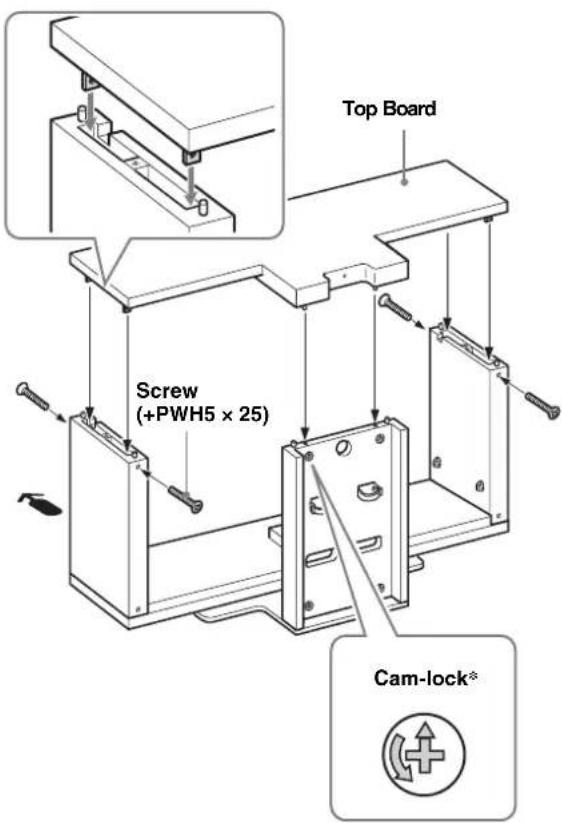
* Before attaching the Top Board, make sure that the mark points upward.
Note
Be careful not to pinch your fingers when attaching the Top Board.
4
Attach the Front Panel to the TV Stand.
① Align the three dowels of the TV Stand with the three holes of the Front Panel.
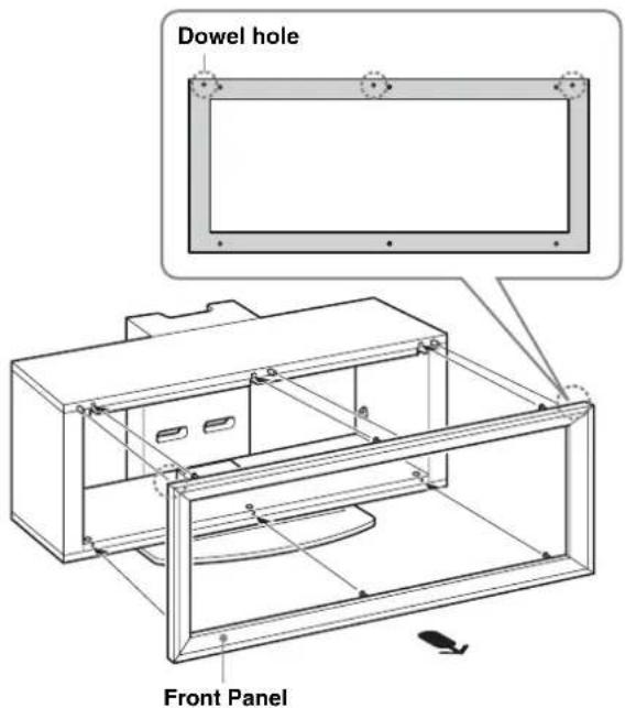
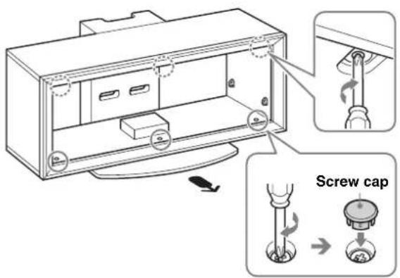
②Turn the six Cam-lock screws on the Top and the Base Boards clockwise to secure the Front Panel. Then, attach the three supplied screw caps to the three bottom screws.
Note
Be sure to attach the Front Panel in the correct direction.
5
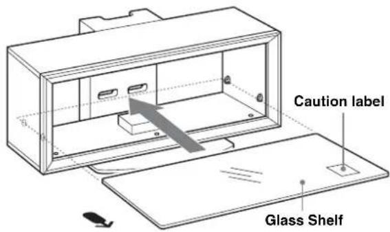
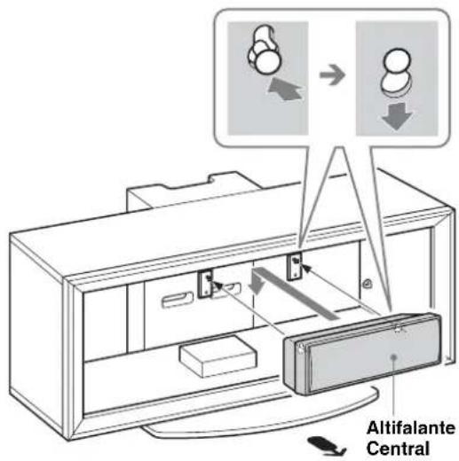
Attach the Glass Shelf.
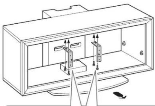
If you attach the Home Theatre System to the Stand, attach the Speaker Hooks first. (Refer to “Installing the Center Speaker (For Home Theatre Systems only)” on page 11.)
① Fully insert the Glass Shelf until it touches the Rear Pillar.
Note
Attach the Glass Shelf to the TV Stand with the Caution label facing up on the front right, as shown in the illustration.
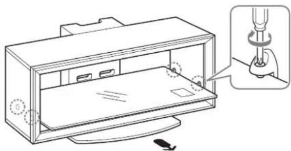
② Tighten the four screws on the Side Pillars to secure the Glass Shelf to the TV Stand.
natural_image
Technical line drawing of a device casing with a close-up inset showing a screwdriver inserted into a housing (no text or symbols present)Step 3: Preparing for the installation of the TV
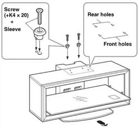
1
Attach the sleeves to the Top Board.
Attach the sleeves with the supplied screws (+K4 × 20).
For models that are not specified on page 2:
Use the front holes.
For models that are specified on page 2:
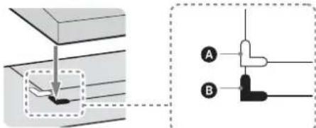
For swivel models*, use the rear holes; for non-swivel models, use the front holes.
Note
Check your TV's operating instructions as to whether or not your TV can swivel.
* The swivel function allows you to adjust the viewing angle of the TV (left and right).
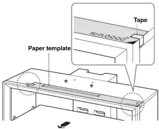
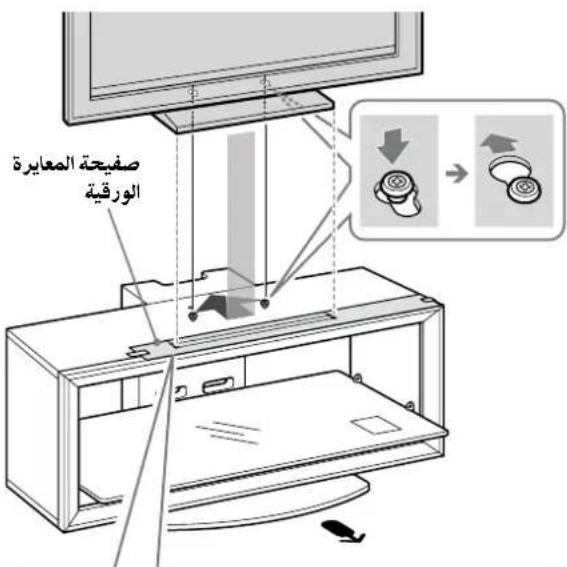
2
Paste the supplied paper template on the Top Board.
① Choose the supplied paper template and align the right corner edges of the paper template with the right corner of the Top Board.
For models that are not specified on page 2: Be sure to refer to the leaflet supplied with your TV, choose the paper template corresponding to your TV.
For models that are specified on page 2:
Choose the paper template in black print corresponding to your TV screen size.
② Tape the paper template to the Top Board with the supplied tape.
Step 4: Installing the TV
Attach your TV to the Table-Top Stand if it is not already attached.
Only for the specified swivel models on page 2, follow the procedure part 1 of Step 4.
1 Adjust the position of the swivel plate to the center (For swivel models only).
Before installing the TV, align the tab of the swivel plate with the notch in the Table-Top Stand.
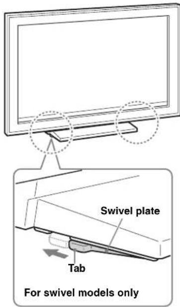
WARNING
If the swivel plate is not adjusted correctly, the TV will not be installed securely and it may fall.
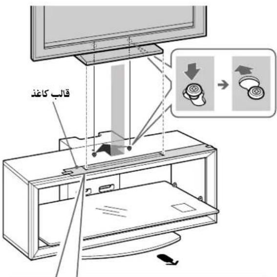
2 Install the TV onto the TV Stand.
① Match the outline of the Table-Top Stand to the outline of the TV screen size and corner marks on the paper template, so that the holes at the bottom of the Table-Top Stand align to the sleeves which were attached in part 1 of Step 3.
②Slide the TV back to lock into place.
③Remove the paper template from the Top Board.
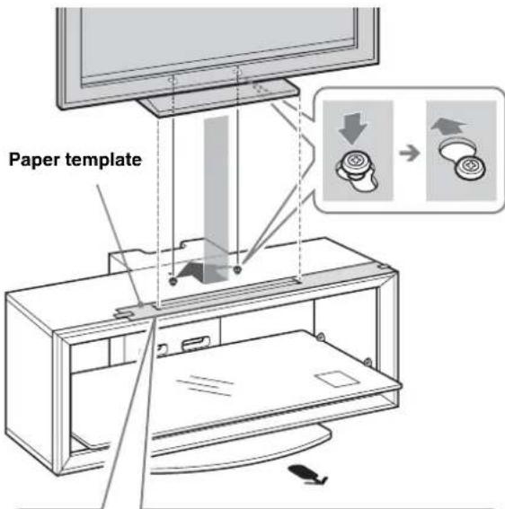
Only for the specified swivel models on page 2
A The white corner mark is for swivel models.
B The black corner mark is for non-swivel models.
Note
For 37/40 inch users, whether the TV is swivel model or not, align the Table-Top Stand with the black corner mark. (There is no white corner mark on the paper template for 37/40 inch.)
3 Attach the anchor bolts.
Secure the two supplied anchor bolts to the rear of the TV.
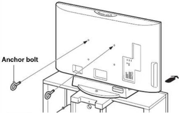
Note
If the two anchor bolts are not used to secure the TV, it may fall and cause injury.
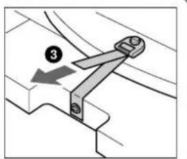
Step 5: Safety measures to prevent toppling over
WARNING
Be sure to take measures to prevent the TV Stand from toppling over, and causing possible injury and damage.
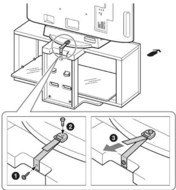
1 Attach the support belt.
①Screw the support belt to the TV Stand with the supplied wood screw using the screwdriver.
② Attach the support belt to the Table-Top Stand, and screw the belt with the supplied securing screw using a coin, etc.
③ Adjust the length by tightening the support belt while holding the Table-Top Stand.
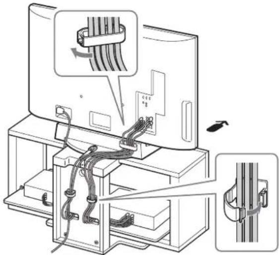
2 Connect the cables.
Run the cables through the cable holders and the Rear Pillar holes.

Note
If the cables are not installed properly, they might be pinched and damaged, and could result in electric shock, etc.
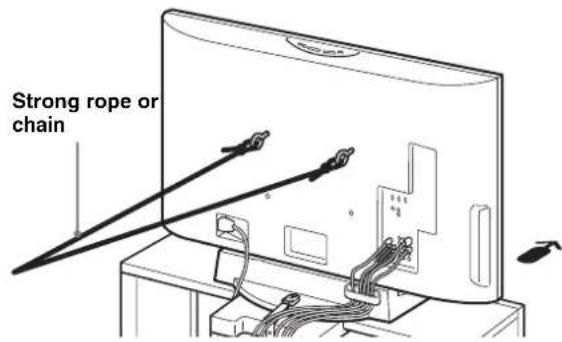
3 Anchor the TV to the wall.
Prepare a strong, commercially-available rope or chain and wall anchor bracket for this purpose.
①Secure the wall anchor bracket to a solid wall.
②Pass the rope or chain through both holes of the anchor bolts and then tighten the other end of the rope or chain to the wall anchor bracket.
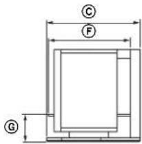
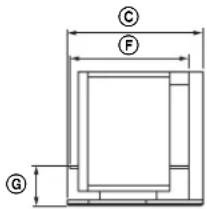
Specifications
natural_image
Pure technical diagram of a mechanical component with no text, numbers, or symbols

Note on carrying capacity
Do not place any equipment on the Glass Shelf which exceeds its maximum weight, as it may break and cause injury.
| SU-FL300M SU-FL300L | |||
| Dimensions: mm (inches) | A1 | ,035(40 3/4) | 1,280(50 1/2) |
| B5 | 03(19 7/8) | 503(19 7/8) | |
| C4 | 85(19 1/8) | 518(20 1/2) | |
| D8 | 95(35 1/4) | 1,140(45) | |
| E3 | 303(12) | 303(12) | |
| F4 | 18(16 1/2) | 468(18 1/2) | |
| G1 | 46(5 3/4) | 146(5 3/4) | |
| H1 | 20(4 3/4) | 130(5 1/8) | |
| I2 | 72(10 3/4) | 340(13 1/2) | |
| Weight: 35 kg | (77 lb 3 oz) | 52 kg(114 lb 11 oz) | |
Design and specifications are subject to change without notice.
Installing the Center Speaker (For Home Theatre Systems only)
The Center Speaker model SS-CT71/CNP2200 is for the following Home Theatre System models:
DAV-HDX665 HT-SF2000
DAV-HDX466 HT-SF1200
DAV-HDX465 HT-SF1100
DAV-HDX267W DAV-DZ750K
DAV-HDX266 DAV-DZ630
DAV-HDX265 DAV-DZ556KB
DAV-HDZ235 DAV-DZ555K
DAV-DZ555M
DAV-DZ530
DAV-DZ250KW
DAV-DZ250K
DAV-DZ250M
DAV-DZ231
DAV-DZ230
DAV-DZ151KB
DAV-DZ150K
The Center Speaker model SS-CT72/CT74 is for the following Home Theatre System models:
DAV-HDX900W DAV-DZ1000
DAV-HDX501W DAV-DZ850KW
DAV-HDX500 DAV-DZ850M
DAV-DZ830W
DAV-DZ531W
Notes
- The products above are subject to change without notice, may be out of stock, or discontinued.
- Certain models may not be available in certain regions.
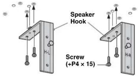
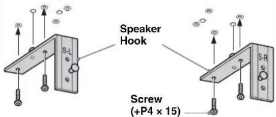
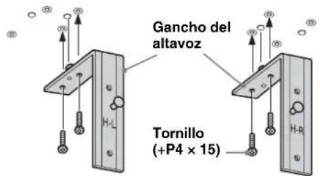
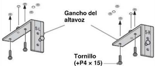
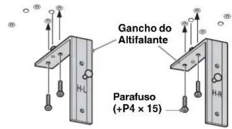
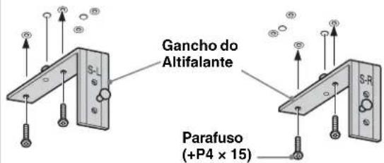
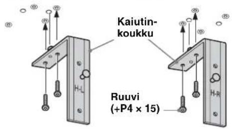
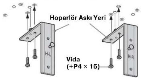
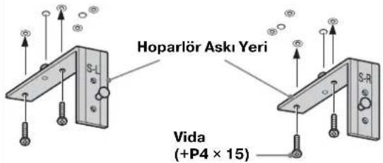
Before attaching the Speaker Hook:
For SS-CT71/CNP2200, the H-L/H-R markings should face forward. (H-L is for the left side, H-R is for the right side.)
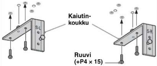
For SS-CT72/CT74, the S-L/S-R markings should face forward. (S-L is for the left side, S-R is for the right side.)
1 Attach the Speaker Hook.
Secure each Speaker Hook with the supplied screws (+P4 × 15) (two screws each for left/right) to the under side of the Top Board.
natural_image
Line drawing of a TV box with two hanging connectors and a triangular base, no text or symbols presentCenter Speaker: SS-CT71/CNP2200
Center Speaker: SS-CT72/CT74
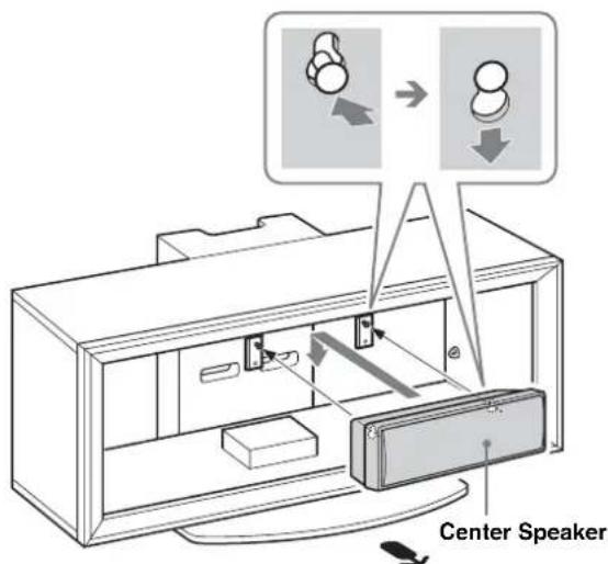
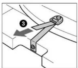
2 Hang the Center Speaker onto the hook screws as shown.
Transport du support TV
natural_image
Illustration of a person using a vacuum cleaner next to a TV (no text or symbols present)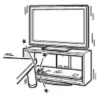
natural_image
Illustration of a person assembling or sorting electronic devices into storage compartments (no text or symbols visible)É tape 2 : Montage du support TV
AVERTISSEMENT
natural_image
Technical line drawing of a device casing with a close-up inset showing a mechanical component (no text or symbols)Remarque
natural_image
Pure technical diagram of a mechanical component with no text, numbers, or symbols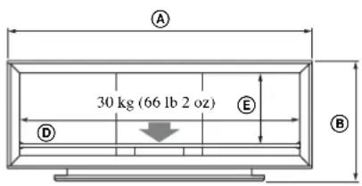

DAV-HDX501W DAV-DZ850KW
DAV-HDX500 DAV-DZ850M
DAV-DZ830W
DAV-DZ531W
Remarques
natural_image
Line drawing of a TV set with two doors and directional arrows indicating movement (no text or symbols)natural_image
Illustration of a person using a vacuum cleaner to clean the TV (no text or symbols present)
natural_image
Illustration of a person assembling or sorting electronic components (no text or symbols visible)natural_image
Technical line drawing of a device casing with a close-up inset showing a mechanical component (no text or symbols)2 Conecte los cables.
Nota
natural_image
Pure technical diagram of a mechanical component with no text, numbers, or symbols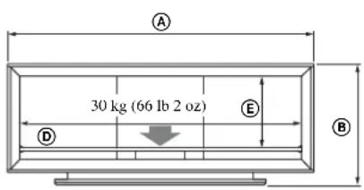

DAV-HDX501W DAV-DZ850KW
DAV-HDX500 DAV-DZ850M
DAV-DZ830W
DAV-DZ531W
Notas
natural_image
Technical line drawing of a metal L-shaped bracket with mounting holes and a hatched base (no text or symbols)natural_image
Technical line drawing of a cabinet or enclosure with internal components and mounting base (no text or symbols)Altavoz central: SS-CT71/CNP2200
Altavoz central: SS-CT72/CT74
natural_image
Illustration of a person using a vacuum cleaner to clean the TV (no text or symbols present)
Nota sobre a capacidade de carga
natural_image
Illustration of a person assembling electronic components with no visible text or symbols2 Fixe as Colunas Laterais à Placa Base.
Fixe as Colunas Laterais e a Placa Base com os quatro parafusos fornecidos (+PWH5 × 25).
Nota
Nota
natural_image
Technical line drawing of a device casing with a screwdriver inserted, showing internal components and a close-up view (no text or symbols)Fixe as buchas na Placa Superior.
Fixe as buchas com os parafusos fornecidos (+K4 × 20).
2 Ligue os cabos.
Nota
natural_image
Pure technical diagram of a mechanical component with labeled dimensions (① and ②) and no readable text or symbols.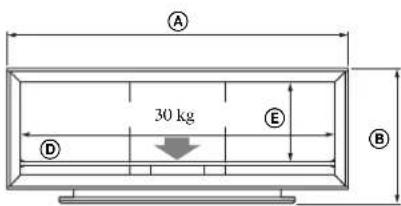
Nota sobre a capacidade de carga
natural_image
Technical line drawing of a metal L-shaped bracket with mounting holes and a labeled section (no text or symbols beyond basic lines)natural_image
Line drawing of a TV set with two rectangular panels and directional arrows indicating movement or force (no text or symbols)Altifalante Central: SS-CT71/CNP2200
Altifalante Central: SS-CT72/CT74
2
Pendure o Altifalante Central nos parafusos do gancho, conforme ilustrado.
natural_image
Illustration of a person using a vacuum cleaner to clean the TV (no text or symbols present)
natural_image
Illustration of a person assembling electronic devices with no visible text or symbolsnatural_image
Technical line drawing of a device casing with a close-up inset showing a hand operating a screwdriver (no text or symbols present)2 Tilslut kablerne.
Bemærk
natural_image
Pure technical diagram of a mechanical component with no text, numbers, or symbols

DAV-HDX501W DAV-DZ850KW
DAV-HDX500 DAV-DZ850M
DAV-DZ830W
DAV-DZ531W
Bemærk
natural_image
Line drawing of a cabinet with two hanging components and a base mount (no text or symbols)natural_image
Illustration of a person using a vacuum cleaner to clean the TV (no text or symbols present)
natural_image
Illustration of a person assembling electronic devices with circuit boards (no text or symbols visible)Pass på at du ikke skader hender eller fingre under montering.
Merk
natural_image
Technical line drawing of a device housing with a close-up inset showing a screwdriver inserted into a component (no text or symbols present)Merk
natural_image
Technical line drawing of a device with a cable inserted into a rack, showing internal components and a directional arrow (no text or symbols)
2
Koble til kablene.
Merk
natural_image
Pure technical diagram of a mechanical component with dimension labels (① and ②) and no readable text or symbols.

DAV-HDX501W DAV-DZ850KW
DAV-HDX500 DAV-DZ850M
DAV-DZ830W
DAV-DZ531W
Merknader
natural_image
Line drawing of a TV set with two connectors and a speaker, no text or symbols presentnatural_image
Illustration of a person using a vacuum cleaner to clean the TV (no text or symbols present)
natural_image
Illustration of a person assembling electronic devices with no visible text or symbolsnatural_image
Technical line drawing of a device casing with a close-up inset showing a screwdriver inserted into a housing (no text or symbols present)Steg 4: Installera TV:n
Obs!
2 Anslut kablarna.
Obs!
natural_image
Pure technical diagram of a mechanical component with no text, numbers, or symbols

DAV-HDX501W DAV-DZ850KW
DAV-HDX500 DAV-DZ850M
DAV-DZ830W
DAV-DZ531W
Obs!
natural_image
Line drawing of a computer monitor case with indicator lights and a base mount (no text or symbols)Centerhögtalare: SS-CT71/CNP2200
Centerhögtalare: SS-CT72/CT74
2
natural_image
Illustration of a person using a vacuum cleaner to clean the TV (no text or symbols present)
natural_image
Illustration of a person assembling or sorting electronic devices into storage compartments (no text or symbols visible)natural_image
Technical line drawing of a device casing with a close-up inset showing a mechanical component (no text or symbols)Vaihe 4: Television asentaminen
2 Kytke kaapelit.
Huomautus
natural_image
Pure technical diagram of a mechanical component with labeled dimensions (H and I), no text or symbols present.
DAV-HDX501W DAV-DZ850KW
DAV-HDX500 DAV-DZ850M
DAV-DZ830W
DAV-DZ531W
Huomautuksia
natural_image
Line drawing of a computer case with two hanging components and a base panel, no text or symbols presentKeskikaiutin: SS-CT71/CNP2200
Keskikaiutin: SS-CT72/CT74
natural_image
Illustration of a person using a vacuum cleaner to clean the TV (no text or symbols present)
natural_image
Illustration of a person assembling electronic devices with circuit boards and components (no text or symbols visible)natural_image
Line drawing of a device housing with a close-up inset showing a screwdriver inserted into a component (no text or symbols)Opmerking
Opmerking
natural_image
Pure technical diagram of a mechanical component with no text, numbers, or symbols

DAV-HDX501W DAV-DZ850KW
DAV-HDX500 DAV-DZ850M
DAV-DZ830W
DAV-DZ531W
Opmerkingen
natural_image
Line drawing of a TV set with two doors and a speaker, showing internal components and sound lines (no text or symbols)natural_image
Illustration of a person using a vacuum cleaner to clean the TV (no text or symbols present)natural_image
Illustration of a person assembling or sorting electronic devices (no text or symbols visible)natural_image
Technical line drawing of a device casing with a close-up inset showing a hand operating a screwdriver (no text or symbols present)Hinweis
natural_image
Pure technical diagram of a mechanical component with dimension labels (① and ②) and no readable text or symbols.

DAV-HDX501W DAV-DZ850KW
DAV-HDX500 DAV-DZ850M
DAV-DZ830W
DAV-DZ531W
Hinweise
natural_image
Line drawing of a computer monitor case with two hanging connectors and a base panel, no text or symbols presentnatural_image
Illustration of a person using a vacuum cleaner next to a TV, with no visible text or symbols
natural_image
Illustration of a person assembling or sorting electronic devices into storage compartments (no text or symbols visible)Nota
natural_image
Line drawing of a device housing with a close-up view showing a screwdriver inserted into a component (no text or symbols present)2 Collegare i cavi.
Nota
DAV-HDX501W DAV-DZ850KW
DAV-HDX500 DAV-DZ850M
DAV-DZ830W
DAV-DZ531W
Note
natural_image
Line drawing of a cabinet interior with hanging connectors and a base panel, no text or symbols presentnatural_image
Illustration of a person using a vacuum cleaner next to a TV, with no visible text or symbolsnatural_image
Illustration of a person assembling electronic devices with no visible text or symbolsnatural_image
Line drawing of a device casing with a hand inserting a screwdriver into it (no text or symbols)Σημείωση
natural_image
Pure technical diagram of a mechanical component with labeled dimensions (H and I), no text or symbols present.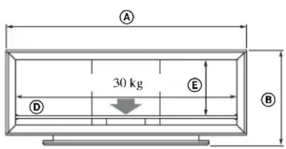

DAV-HDX501W DAV-DZ850KW
DAV-HDX500 DAV-DZ850M
DAV-DZ830W
DAV-DZ531W
Σημειώσεις
natural_image
Line drawing of a computer case with two hanging devices and a base panel, no text or symbols presentnatural_image
Illustration of a person using a vacuum cleaner to clean the TV (no text or symbols present)natural_image
Illustration of a person assembling electronic devices with no visible text or symbolsnatural_image
Technical line drawing of a device casing with a close-up inset showing a mechanical component (no text or symbols)War 3.
natural_image
Technical line drawing of a device with a lock mechanism and mounting bracket (no text or symbols)
Примечание
DAV-HDX501W DAV-DZ850KW
DAV-HDX500 DAV-DZ850M
DAV-DZ830W
DAV-DZ531W
Примечания
natural_image
Technical line drawing of a metal bracket with mounting holes and wiring (no text or symbols)natural_image
Technical line drawing of a cabinet with two hanging components and a base, no text or symbols presentnatural_image
Illustration of a person using a vacuum cleaner to clean the TV (no text or symbols present)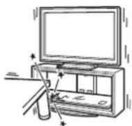
natural_image
Illustration of a person assembling or sorting electronic components (no text or symbols visible)natural_image
Technical line drawing of a device casing with a close-up inset showing a screwdriver inserted into a housing (no text or symbols present)Uwaga
natural_image
Pure technical diagram of a mechanical component with dimension labels (① and ②) and no readable text or symbols.

DAV-HDX501W DAV-DZ850KW
DAV-HDX500 DAV-DZ850M
DAV-DZ830W
DAV-DZ531W
Uwaga
natural_image
Line drawing of a TV set with two-mounted speakers and a speaker, no text or symbols presentnatural_image
Illustration of a person using a vacuum cleaner to clean the TV (no text or symbols present)
Poznámka k nosnosti
natural_image
Illustration of a person assembling electronic devices with circuit boards (no text or symbols visible)natural_image
Technical line drawing of a device casing with a close-up view showing internal components and a mechanical component inserted (no text or symbols)Krok 3: Příprava k instalaci televizoru
1
Poznámka
natural_image
Pure technical diagram of a mechanical component with dimension labels (H and I) and no readable text or symbols.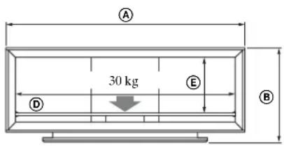

Poznámka k nosnosti
DAV-HDX501W DAV-DZ850KW
DAV-HDX500 DAV-DZ850M
DAV-DZ830W
DAV-DZ531W
Poznámky
natural_image
Line drawing of a cabinet interior with mounting base and support structure (no text or symbols)natural_image
Illustration of a person using a vacuum cleaner next to a TV (no text or symbols present)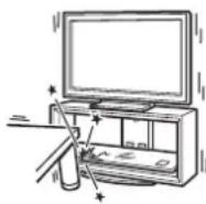
Poznámka k nosnosti
natural_image
Illustration of a person assembling electronic components with trays and bins (no text or symbols)natural_image
Technical line drawing of a device casing with a close-up inset showing a screwdriver inserted into it (no text or symbols present)2 Pripojte káble.
Káble vedte cez držiaky káblov a otvory v zadnom stípiku.
Poznámka
natural_image
Pure technical diagram of a mechanical component with no text, numbers, or symbols

Poznámka k nosnosti
DAV-HDX501W DAV-DZ850KW
DAV-HDX500 DAV-DZ850M
DAV-DZ830W
DAV-DZ531W
Poznámky
natural_image
Illustration of a person using a vacuum cleaner to clean the TV (no text or symbols present)
natural_image
Illustration of a person assembling electronic devices with no visible text or symbolsnatural_image
Technical line drawing of a device housing with a close-up inset showing a screwdriver inserted into a component (no text or symbols present)Megjegyzés
natural_image
Pure technical diagram of a mechanical component with no text, numbers, or symbols

DAV-HDX501W DAV-DZ850KW
DAV-HDX500 DAV-DZ850M
DAV-DZ830W
DAV-DZ531W
Megjegyzések
natural_image
Technical line drawing of a metal L-shaped bracket with mounting holes and a connecting rod (no text or symbols)natural_image
Line drawing of a computer monitor with visible internal components and a base mount (no text or symbols)natural_image
Illustration of a person using a vacuum cleaner to clean the TV (no text or symbols present)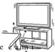
natural_image
Illustration of a person assembling or sorting electronic components (no text or symbols visible)natural_image
Technical line drawing of a device casing with a close-up inset showing a hand operating a screwdriver (no text or symbols present)Not
natural_image
Pure technical diagram of a mechanical component with labeled dimensions (H and I), no text or symbols present.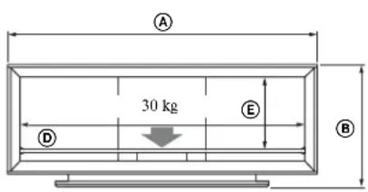

DAV-HDX501W DAV-DZ850KW
DAV-HDX500 DAV-DZ850M
DAV-DZ830W
DAV-DZ531W
Notlar
natural_image
Line drawing of a TV set with mounted connectors and a small object on the floor (no text or symbols)Orta Hoparlör: SS-CT71/CNP2200
Orta Hoparlör: SS-CT72/CT74
natural_image
Illustration of a person using a vacuum cleaner to clean the TV (no text or symbols present)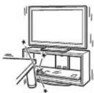
承載重量的注意事項
natural_image
Illustration of a person assembling or sorting electronic devices into storage bins (no text or symbols visible)natural_image
Technical line drawing of a device casing with a close-up view showing internal components and a tool inserted (no text or symbols)步驟 3: 準備安裝電視
1 將套管安裝到頂板上。
2 連接線路。
將線路穿過線路固定裝置和後柱孔。

注意
natural_image
Pure technical diagram of a mechanical component with no text, numbers, or symbols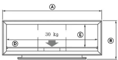
承載重量的注意事項
natural_image
Technical line drawing of a metal bracket with mounting holes and wiring (no text or symbols)SS-CT72/CT74
的揚聲器掛鉤螺絲
SS-CT71/CNP2200
的揚聲器掛鉤螺絲
1 安装揚聲器掛鉤。
natural_image
Line drawing of a computer monitor case with internal components and a base, no text or symbols presentnatural_image
Illustration of a person using a vacuum cleaner to clean the TV (no text or symbols present)
natural_image
Illustration of a person assembling or sorting electronic devices into storage compartments (no text or symbols visible)หมายเหตุ
natural_image
Technical line drawing of a device casing with a close-up inset showing a mechanical component (no text or symbols)ขั้นที่ 3:
หมายเหตุ
DAV-HDX501W DAV-DZ850KW
DAV-HDX500 DAV-DZ850M
DAV-DZ830W
DAV-DZ531W
หมายเหตุ
natural_image
Line drawing of an open computer case with two vertical connectors and a base panel, no text or symbols presentnatural_image
Illustration of a person using a vacuum cleaner to clean the TV (no text or symbols present)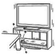
적재량에 관한 주의
natural_image
Illustration of a person assembling or sorting electronic components (no text or symbols visible)natural_image
Line drawing of a computer case with an inset showing a screwdriver inserted into a housing (no text or symbols present)3 단계:
TV설치 준비하기
1 슬리브를 상판에 부착합니다.
2 케이블을 연결합니다.
주의점
DAV-HDX501W DAV-DZ850KW
DAV-HDX500 DAV-DZ850M
DAV-DZ830W
DAV-DZ531W
주의점
natural_image
Line drawing of an open computer case with hanging weights and a mouse, no text or symbols presentnatural_image
Line drawing of a computer monitor case with two internal components and a base panel, no text or symbols presentDAV-DZ850KW DAV-HDX501W
DAV-DZ850M DAV-HDX500
DAV-DZ830W
DAV-DZ531W
نکات
natural_image
Technical line drawing of a metal L-shaped bracket with mounting holes and a hatched section (no text or symbols)نكته
natural_image
Technical line drawing of a device with a magnified inset showing internal components (no text or symbols)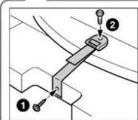
1
natural_image
Technical line drawing of a device casing with a close-up view showing internal components and a mechanical component inserted (no text or symbols)مرحله ٣:
The image is too blurry to recognize any text content.
natural_image
Illustration of a person assembling electronic devices with no visible text or symbolsnatural_image
Illustration of a person using a vacuum cleaner to clean the TV (no text or symbols present)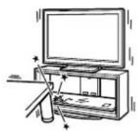
NZDÍK IČ K BCHARÍ QRA R D A R D NCSB NKNID.
natural_image
Line drawing of a TV set with two-mounted devices and a speaker, no text or symbols presentDAV-DZ850KW DAV-HDX501W
DAV-DZ850M DAV-HDX500
DAV-DZ830W
DAV-DZ531W
ملاحظات
ملاحظة
natural_image
Technical line drawing of a device with a magnified inset showing internal components (no text or symbols)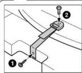
natural_image
Technical line drawing of a device casing with internal components and a close-up view of the component being inserted (no text or symbols present)الخطوة ٢:
natural_image
Illustration of a person assembling electronic components with no visible text or symbols
- Thank you for purchasing this product.
- For customers
- WARNING
- For Sony dealers
- On Safety
- CAUTION
- Specified products
- Products should only be installed by qualified Sony service representatives.
- Be sure to take measures to prevent the TV Stand from toppling over.
- Be sure to install the TV Stand on a solid and flat floor.
- Do not use a cracked TV Stand.
- Do not lean on or hang from the TV.
- Do not allow children to climb on the TV Stand or crawl between the shelves.
- Do not step on the TV Stand.
- Do not cover the ventilation holes of the TV.
- Do not allow the AC power cord or the connecting cable to be pinched.
- Do not move the TV Stand with the TV attached or with connected equipment inside.
- Do not install any equipment other than the specified product.
- Be sure to secure the TV.
- Do not apply weight to the glass or subject it to any kind of impact.
- When carrying the TV Stand
- Do not subject the glass to excessive shock.
- Note on carrying capacity
- Notes on installation
- Note on use
- To Sony dealers
- Be sure that two or more persons do the installation work.
- Be sure to assemble the TV Stand securely following the instructions.
- Be careful not to injure your hands or fingers while assembling.
- Be sure to install the TV securely following the instructions.
- Step 1: Checking the parts
- Step 2: Assembling the TV Stand
- Decide on the installation location and lay the TV Stand down before installing the TV.
- Attach the Rear Pillar to the Base Board.
- Attach the Side Pillars to the Base Board.
- Note
- 3
- Attach the Top Board.
- 4
- Attach the Front Panel to the TV Stand.
- 5
- Attach the Glass Shelf.
- Step 3: Preparing for the installation of the TV
- 1
- Attach the sleeves to the Top Board.
- 2
- Paste the supplied paper template on the Top Board.
- Step 4: Installing the TV
- Adjust the position of the swivel plate to the center (For swivel models only).
- Install the TV onto the TV Stand.
- Attach the anchor bolts.
- Step 5: Safety measures to prevent toppling over
- Attach the support belt.
- Connect the cables.
- Anchor the TV to the wall.
- Specifications
- Installing the Center Speaker (For Home Theatre Systems only)
- Notes
- Before attaching the Speaker Hook:
- Attach the Speaker Hook.
- Hang the Center Speaker onto the hook screws as shown.
- Transport du support TV
- É tape 2 : Montage du support TV
- AVERTISSEMENT
- Remarque
- Remarques
- Conecte los cables.
- Nota
- Notas
- Nota sobre a capacidade de carga
- Fixe as Colunas Laterais à Placa Base.
- Fixe as buchas na Placa Superior.
- Ligue os cabos.
- Tilslut kablerne.
- Bemærk
- Pass på at du ikke skader hender eller fingre under montering.
- Merk
- Koble til kablene.
- Merknader
- Steg 4: Installera TV:n
- Obs!
- Anslut kablarna.
- Vaihe 4: Television asentaminen
- Kytke kaapelit.
- Huomautus
- Huomautuksia
- Opmerking
- Opmerkingen
- Hinweis
- Hinweise
- Collegare i cavi.
- Σημείωση
- Σημειώσεις
- War 3.
- Примечание
- Примечания
- Uwaga
- Poznámka k nosnosti
- Krok 3: Příprava k instalaci televizoru
- Poznámka
- Poznámky
- Pripojte káble.
- Megjegyzés
- Megjegyzések
- Not
- Notlar
- 承載重量的注意事項
- 步驟 3: 準備安裝電視
- 將套管安裝到頂板上。
- 連接線路。
- 注意
- 安装揚聲器掛鉤。
- หมายเหตุ
- ขั้นที่ 3:
- 적재량에 관한 주의
- 단계:
- TV설치 준비하기
- 슬리브를 상판에 부착합니다.
- 케이블을 연결합니다.
- 주의점
- نکات
- ملاحظات
- الخطوة ٢:
Brand : SONY
Model : SUFL300M
Category : TV Stand