USER MANUAL PS 254 L AEG
Original instructions
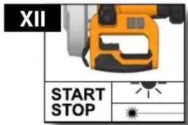
| Technical Data,Safety Instructions, Specified Conditions of Use,EC-Declaration of Conformity, Mains connection, Maintenance, Symbols | Please read and save these instructions! | English | 30 |
| Technische Daten, Sicherheitshinweise, Bestimmungsgemäße Verwendung,CE-Konformitätserklärung, Netzanschluss, Wartung, Symbole | Bitte lesen und aufbewahren! | Deutsch | 35 |
| Caractéristiques techniques, Instructions de sécurité, Utilisation conforme aux prescriptions, Déclaration CE de Conformité, Branchement secteur, Entretien, Symboles | A lire et à conserver soigneusement | Français | 41 |
| Dati tecnici, Norme di sicurezza, Utilizzo conforme, Dicharazione di Conformità CE, Collegamento alla rete, Manutenzione, Simboli | Si prega di leggere e conservare le istruzioni! | Italiano | 47 |
| Datos técnicos, Instrucciones de seguridad, Aplicación de acuerdo a la finalidad,Declaracion de Conformidad CE, Conexión eléctrica, Mantenimiento, Simbolos | Lea y conserve estas instrucciones por favor! | Español | 53 |
| Características técnicas, Instruções de segurança, Utilização autorizada,Declaração de Conformidade CE, Ligação à rede, Manutenção, Symbole | Por favor leia e conserve em seu poder! | Português | 59 |
| Technische gegevens, Veiligheidsadviezen, Voorgeschreven gebruik van het systeem, EC-Konformiteitsverklaring, Netaansluiting,Onderhoud, Symbolen | Lees en let goed op deze adviezen! | Nederlands | 65 |
| Tekniske data, Sikkerhedshenvisninger, Tiltænkt formål,CE-Konformitetserklæring, Nettislutning, Vedligeholdelse, Symboler | Vær venlig at læse og opbevar! | Dansk | 71 |
| Tekniske data, Spesielle sikkerhetshenvisninger, Formålsmessig bruk,CE-Samsvarserklæring, Nettilkopling, Vedlikehold, Symboler | Vennligst les og oppbevar! | Norsk | 77 |
| Tekniska data, Säkerhetsutrustning, Använd maskinen Enligt anvisningarna,CE-Försäkran, Nätanslutning, Skötsel, Symboler | Läs igenom och spara! | Svenska | 82 |
| Tekniset arvot, Turvallisuusohjeet, Tarkoituksenmukainen käyttö,Todistus CE-standardinmukaisuudesta, Verkkoliitäntä, Huolto, Symbolit | Lue ja säilytä! | Suomi | 88 |
| Teyniká στοχεία, Ειδικές υποδείξεις ασφάλειας, Χρήση σύμφωνα με το σκοπό προοριομού, Δήλωση πιστότητας ΕΚ, Σύνδεση στο Ηλεκτρικό Δίκτυο, Συντήρηση, Σύμβολα. | Παρακαλούμε να τις διαβάσετε και να τις φυλάξετε! | Ελληνικά | 93 |
| Teknik veriler, Güvenliğiniz için talimatlar, Kullanim, CE uygunluk beyanice,Sebeke bağlantisi, Bakim, Semboller | Lütfen okuyun ve saklayın | Türkçe | 99 |
| Technická data, Speciální bezpečnostní upozornění, Oblast využití,CE-prohlášení o shodě, Připojení na sít, Údržba, Symboly | Po přečtení uschovejte | Česky | 104 |
| Technické údaje, Špeciálne bezpčenostné pokyny, Použitie podl’a predpisov,CE-Vyhlásenie konformity, Siet’ová prípojka, Údrzba, Symboly | Prosím prečitaťa uschovat! | Slovensky | 109 |
| Dane techniczne, Specjalne zalecenia dotyczące bezpieczeństwa, Użytkowanie zgodne z przeznaczeniem, Świadectwo zgodnościce, Podłączenie do sieci, Utrzymanie, Symbole | Należy uważnie przeczytać i zachować do wglądu! | Polski | 114 |
| Műszaki adatok, Különleges biztonsági tudnivalók, Rendeltetésszerű használat,Ce-azonossági nyilatkozat, Hálózati csatlakoztatás, Karbantartás, Szimbólumok | Olvassa el és őrizze meg | Magyar | 120 |
| Tehnični podatki, Specialni varnostní napotki, Uporaba v skladu z namembnostjo,CE-izjava o konformnosti, Omrežni priključek, Vzdřževanje, Simboli | Prosimo preberite in shranite! | Slovensko | 126 |
| Tehnički podaci, Specijalne sigurnosne upute, Propisna upotreba,CE-Izjava konformnosti, Priključak na mrežu, Održavanje, Simboli | Molimo pročitati i sačuvati | Hrvatski | 131 |
| Tehniskie dati, Speciālie drošības noteikumi, Noteikumiem atbilstošs izmantojums,Atbilstība CE normām, Tikla pieslēgums, Apkope, Simboli | Lūdzu, izlasīt un uzglabāt! | Latviski | 136 |
| Techniniai duomenys, Ypatingos saugumo nuorodos, Naudojimas pagal paskirti,CE Atitikties pareiškimas, Elektros tinklo jungtis, Techninis aptarnavimas, Simboliai | Prašome perskaityti ir neišmesti! | Lietuviškai | 141 |
| Tehnilised andmed, Spetsiaalsed turvajuhised, Kasutamine vastavalt otstarbele,EÜ Vastavusavaldus, Vörku ühendamine, Hooldus, Sümbolid | Palun lugege läbi ja hoidke alal! | Eesti | 146 |
| Технические данные, Указания по безопасности, Использование, Декларация о соответствии стандартам ЕС, Подключение к электросети, Обслуживание, Символы | Пожалуйста прочите и сохраните эту инструкцию. | Русский | 151 |
| Технически данни, Специални указания за безопасност, Използване по предназначение,CE - Декларация за съответствие, Връзка с Електричество, Поддръжка, Символи | Моля прочетете и запазете! | Български | 158 |
| Date tehnice, Instructiuni de securitate, Conditii de utilizare specificate,Declarație de conformitate, Alimentare de la rețea, Intreținere, Simboluri | Va rugăm citiți și păstrați aceste instrucțiuni | Română | 164 |
| Технички податоци, Упатства за употреба, Специфицирани услови на употреба,ЕУ- декларација за Сообразност, Напојување од мрежата, Одржување, Символи | Ве молиме прочитајте го и чувајте го ова упатство! | Македоћски | 170 |
| Технічні характеристики, Вказівки З Техніки Безпеки, Використання за призначенням, Сертифікат Відповідності Вимогам Єс, Підключення до мережі, Обслуговування, Символи цю інструкцію. | Українська | 176 |
natural_image
Illustration of a cutaw with AEG branding and orange blade, no text or symbols present


natural_image
Two abstract black line shapes with small protrusions, no text or symbols present

natural_image
3D rendered image of a curved mechanical component with black connectors (no text or symbols)


natural_image
Close-up of a gray industrial sensor device with black coiled cable, no visible text or symbols


natural_image
Mechanical assembly diagram showing a valve mechanism with directional arrows (no text or labels)
natural_image
Mechanical robotic arm performing a cutting operation on a workbench (no text or symbols visible)
natural_image
Close-up of a cutting tool with an orange blade and black base, showing a mechanical assembly (no text or symbols visible)
natural_image
Diagram of a cutting tool with a gear and blade, labeled IV (no text or symbols on the diagram itself)
natural_image
Close-up of a mechanical tool with directional arrows indicating movement or force (no text or symbols)
natural_image
Close-up of a mechanical component with a white arrow pointing to a yellow-orange component, no visible text or symbols.
natural_image
Mechanical assembly diagram showing a lever and base components (no text or labels visible)
natural_image
Pure mechanical component diagram without any text, numbers, or symbols
natural_image
Mechanical assembly diagram showing a cutting tool and blade alignment (no text or symbols)
natural_image
Industrial robotic arm and mechanical components with wrench and bracket (no visible text or symbols)
natural_image
Simple line drawing of a wrench with no text or symbols

natural_image
Illustration of a robotic hand holding a padlock, no text or symbols present
natural_image
Mechanical assembly diagram showing a motor with rotating shaft and guide rails (no text or symbols)


natural_image
Mechanical assembly diagram showing a valve mechanism with directional arrows (no text or labels)

natural_image
Mechanical assembly diagram showing a motor with attached shafts and gears, connected by a dashed line (no text or symbols)
natural_image
Mechanical assembly diagram showing a motor with rotating shaft and guide rails (no text or symbols)
natural_image
3D mechanical component with a red X mark and black curved line, no visible text or symbols
natural_image
Close-up of a mechanical component with a green checkmark and black outline (no text or symbols)

natural_image
Blank gray image with no visible content, text, or symbols
natural_image
Mechanical assembly diagram showing a robotic arm operating a workpiece with alignment guides (no text or symbols)


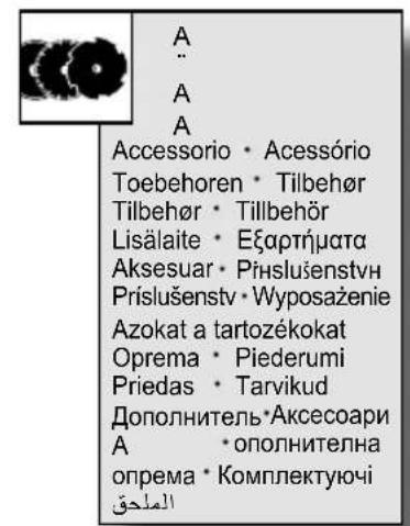
Not included in standard equipment.
natural_image
Illustration of a robotic arm on a cart with directional arrows indicating motion (no text or symbols)
natural_image
Close-up of a mechanical cutting tool with orange and silver blades, showing a yellow blade and black base (no text or symbols visible)
natural_image
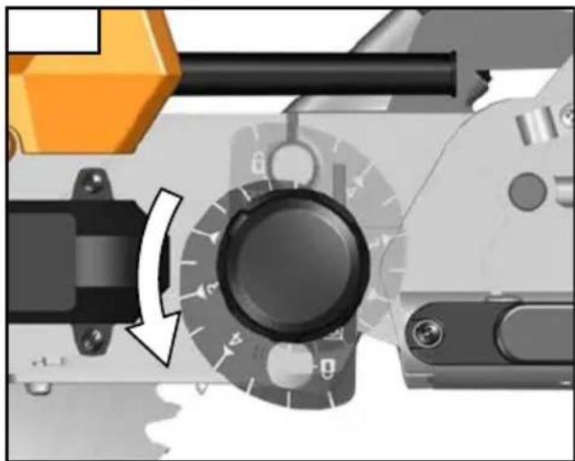
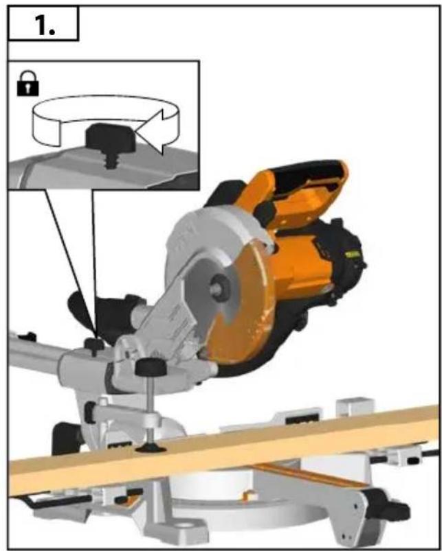
Close-up of a mechanical dial with lock and adjustment knobs (no text or symbols visible)
natural_image
Close-up of a mechanical component with directional arrows indicating movement or force (no text or symbols visible)
natural_image
Close-up of a mechanical device's rotary knob and adjustment knob, showing mechanical components without any text or symbols.
natural_image
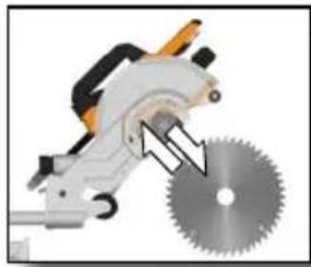
Close-up of a saw cutting tool with a metallic blade and gear, showing a cutting edge (no text or symbols visible)


natural_image
Close-up of a cut tool with a metallic gear and blade, showing a cutting edge (no text or symbols visible)


natural_image
Close-up of a mechanical tool with a gear and blade, showing a cutting edge (no text or symbols visible)

natural_image
Close-up of a mechanical component with arrows indicating direction (no text or symbols visible)

natural_image
Pure mechanical component diagram without any text, numbers, or symbols

natural_image
Mechanical assembly diagram showing a robotic arm with a lock and rotating component (no text or symbols)
natural_image
Mechanical assembly diagram showing a lever mechanism with no visible text or symbols
natural_image
Technical diagram of a mechanical assembly with no visible text or symbols


natural_image
Solid gray rectangular bar with no text, symbols, or discernible features
natural_image
Mechanical assembly diagram showing a lever mechanism with no visible text or symbols
natural_image
Diagram showing a mechanical component with an arrow pointing to a black cylindrical part, and an inset showing flow direction (no text or symbols)

natural_image
Close-up of a black threaded mechanical component with a small arrow pointing to a feature (no text or symbols visible)
natural_image
Pure mechanical component diagram without any text, numbers, or symbols

natural_image
Close-up of a black rubber hose being inserted into a mechanical component, with an arrow indicating the insertion direction (no text or symbols present)
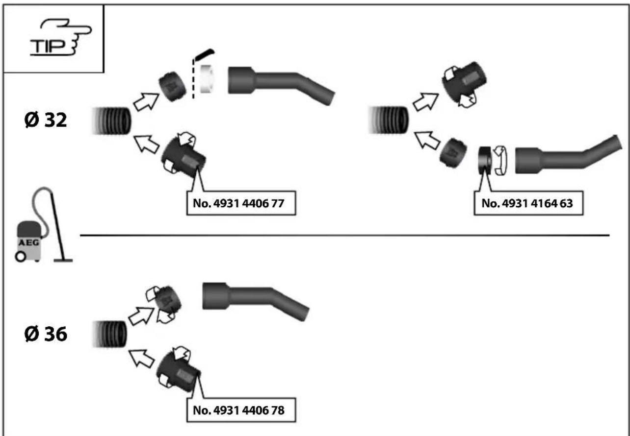
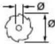
flowchart
graph TD
    A["∅ 32"] --> B["Component 1"]
    B --> C["No. 4931 4406 77"]
    C --> D["Component 2"]
    D --> E["No. 4931 4164 63"]
    F["∅ 36"] --> G["Component 1"]
    G --> H["No. 4931 4406 78"]
natural_image
Diagram of a mechanical or optical setup with directional arrows and shaded regions (no text or symbols)


natural_image
Mechanical assembly diagram showing two directional arrows pointing to components (no text or symbols)

natural_image
Mechanical assembly diagram showing a robotic arm and a green checkmark (no text or symbols)
natural_image
Mechanical assembly diagram showing robotic arm and tool with red X mark and green checkmark (no text or symbols)


natural_image
Illustration of a cutting machine with an orange-handled cutter and workpiece, no text or symbols present
Insulated gripping surface


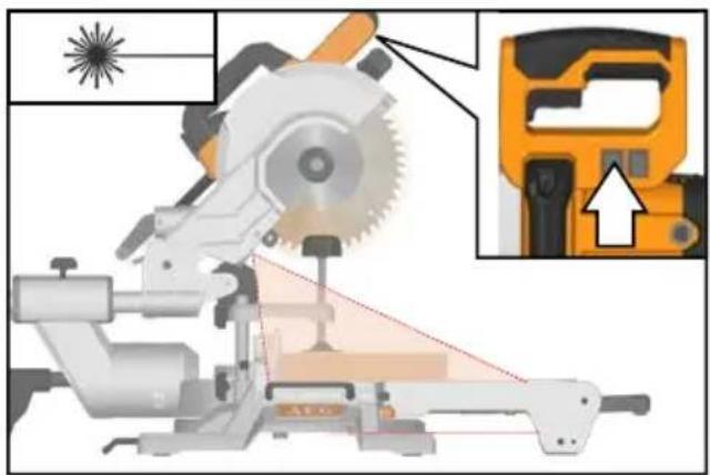
A: 650nm; P≤1mW EN 60825-1:2014


natural_image
Mechanical assembly diagram showing directional arrows indicating motion or force (no text or symbols)


natural_image
Mechanical assembly diagram showing robotic arm and alignment markers (no text or symbols)
natural_image
Mechanical assembly diagram showing a cutting tool with a highlighted blade and orange workpiece (no text or symbols)

natural_image
Mechanical assembly diagram showing gear and cam mechanism with directional arrows (no text or labels)


natural_image
3D rendering of a mechanical power tool with orange and black components, no visible text or symbols
natural_image
Industrial robotic arm with yellow and black components, no visible text or symbols
natural_image
Simple line drawing of a wrench (no text or symbols)
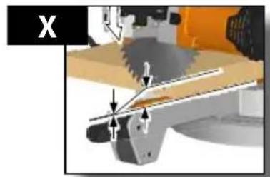
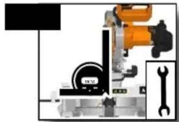
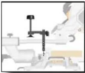
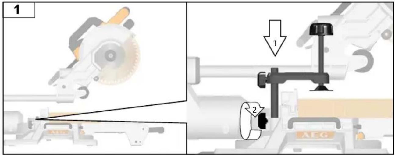
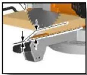
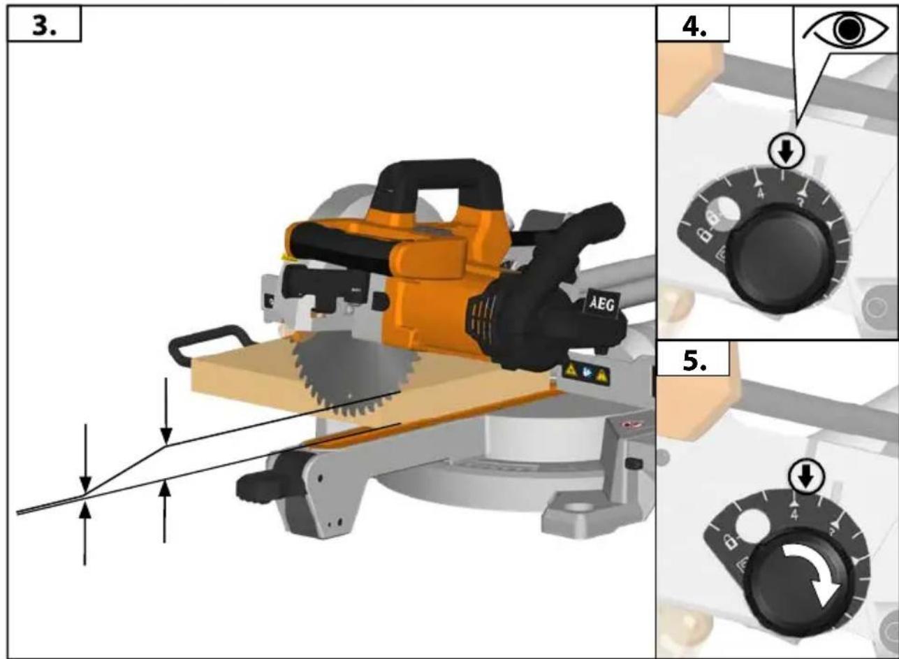
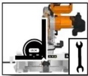
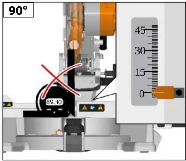
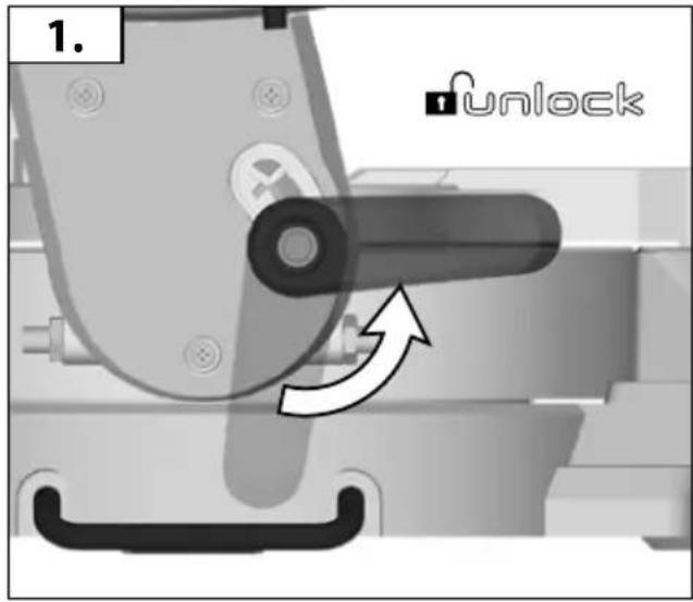
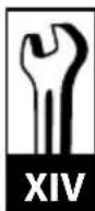
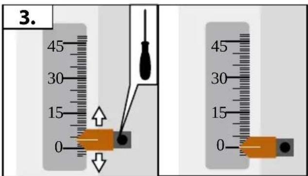
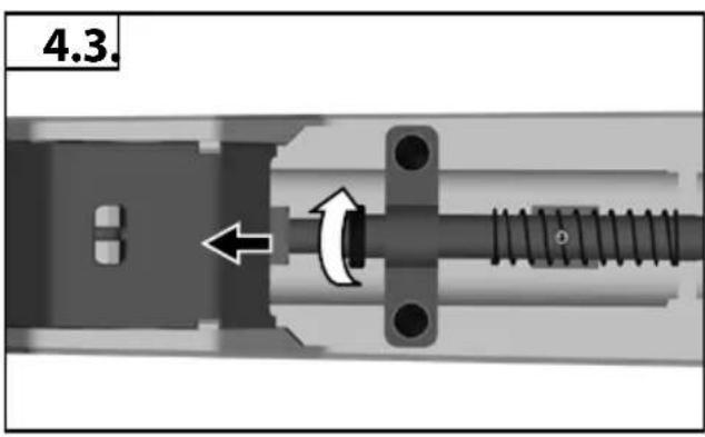
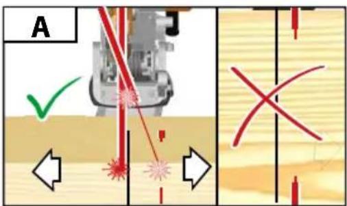
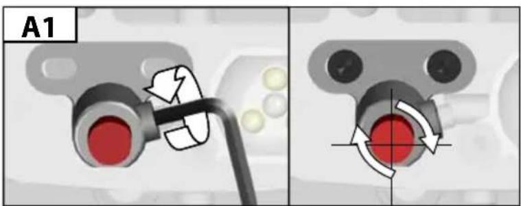
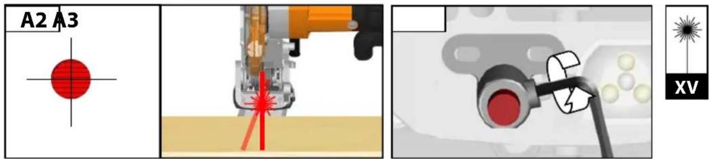
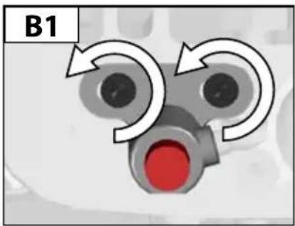
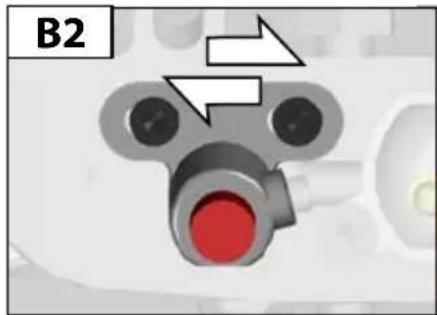
If a correction of the 90° angle of the guide-plate to the saw blade is necessary, use the correction screw.
natural_image
Simple line drawing of a wrench (no text or symbols)
natural_image
Mechanical assembly diagram showing a robotic arm interacting with a lock, with a green checkmark indicating action (no text or symbols present)
natural_image
Mechanical assembly diagram showing a cutting cutter with orange blade and black handle, alongside a close-up of a mechanical component (no text or symbols)

natural_image
Mechanical assembly diagram showing a shaft and spring assembly with directional arrows (no text or symbols)
natural_image
Mechanical assembly diagram showing a shaft and spring mechanism with directional arrow (no text or symbols)
natural_image
Mechanical assembly diagram showing a shaft and housing with directional arrows indicating motion (no text or symbols)
natural_image
Simple line drawing of a wrench (no text or symbols)


natural_image
Simple line drawing of a wrench (no text or symbols)

natural_image
3D mechanical assembly diagram showing a cutting machine with orange internal components and directional arrows indicating motion (no text or symbols)
natural_image
Simple line drawing of a wrench (no text or symbols)
LASER 2
λ: 650nm; P≤1mW EN 60825-1:2014

natural_image
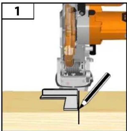
Mechanical robotic arm performing a cutting or extrusion operation with a pencil (no text or symbols visible)
natural_image
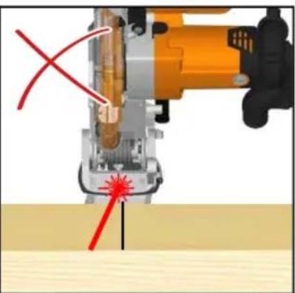
Close-up of a mechanical tool with red annotation lines and a starburst effect, no visible text or symbols
natural_image
Illustration of a cutting cutter and a lathe machine (no text or symbols)
natural_image
Simple line drawing of a wrench (no text or symbols)
A: 650nm; P≤1mW EN 60825-1:2014
natural_image
Diagram of a three-way valve mechanism with red end, showing bidirectional flow arrows (no text or symbols)
natural_image
Close-up of a mechanical component with red circular end and arrow indicator (no text or symbols)
natural_image
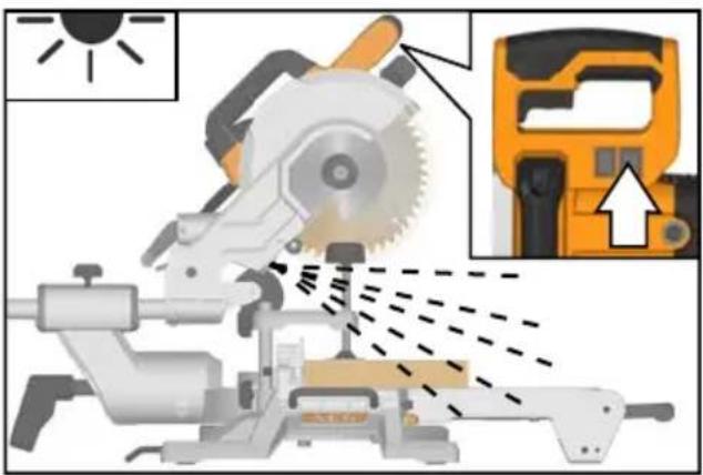
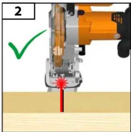
Close-up of a mechanical device emitting red laser beams into a wooden surface, with an arrow indicating direction (no text or symbols)

natural_image
Illustration of a person using a sawtooth tool with an open lock nearby (no text or symbols)


natural_image
Close-up of a mechanical control panel with rotary dial and adjustment knobs (no readable text or symbols)
natural_image
Illustration of a hand holding a saw with a lock symbol (no text or symbols present)


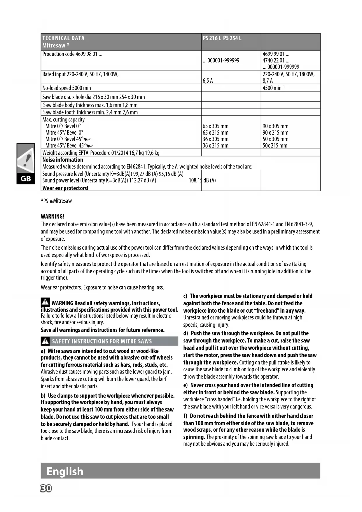
| TECHNICAL DATAMitresaw * | PS 216 L PS 254 L | |
| Production code 4699 98 01 ... | ... 000001-999999 | 4699 99 01 ...4740 22 01 ...... 000001-999999 |
| Rated input 220-240 V, 50 HZ, 1400W, | 6,5 A | 220-240 V, 50 HZ, 1800W,8,7 A |
| No-load speed 5000 min | -1 | 4500 min^-1 |
| Saw blade dia. x hole dia 216 x 30 mm 254 x 30 mm | | |
| Saw blade body thickness max. 1,6 mm 1,8 mm | | |
| Saw blade tooth thickness min. 2,4 mm 2,6 mm | | |
| Max. cutting capacityMitre 0°/ Bevel 0°Mitre 45°/ Bevel 0°Mitre 0°/ Bevel 45°Mitre 45°/ Bevel 45° | 65 x 305 mm65 x 215 mm36 x 305 mm36 x 215 mm | 90 x 305 mm90 x 215 mm50 x 305 mm50x 215 mm |
| Weight according EPTA-Procedure 01/2014 16,7 kg 19,6 kg | | |
| Noise informationMeasured values determined according to EN 62841. Typically, the A-weighted noise levels of the tool are:Sound pressure level (Uncertainty K=3dB(A)) 99,27 dB (A) 95,15 dB (A)Sound power level (Uncertainty K=3dB(A)) 112,27 dB (A) 108,15 dB (A) |
| Wear ear protectors! |
*PS ≅ Mitresaw
WARNING!
The declared noise emission value(s) have been measured in accordance with a standard test method of EN 62841-1 and EN 62841-3-9, and may be used for comparing one tool with another. The declared noise emission value(s) may also be used in a preliminary assessment of exposure.
The noise emissions during actual use of the power tool can differ from the declared values depending on the ways in which the tool is used especially what kind of workpiece is processed.
Identify safety measures to protect the operator that are based on an estimation of exposure in the actual conditions of use (taking account of all parts of the operating cycle such as the times when the tool is switched off and when it is running idle in addition to the trigger time).
Wear ear protectors. Exposure to noise can cause hearing loss.

WARNING Read all safety warnings, instructions,
illustrations and specifications provided with this power tool.
Failure to follow all instructions listed below may result in electric shock, fire and/or serious injury.
Save all warnings and instructions for future reference.

SAFETY INSTRUCTIONS FOR MITRE SAWS
a) Mitre saws are intended to cut wood or wood-like products, they cannot be used with abrasive cut-off wheels for cutting ferrous material such as bars, rods, studs, etc.
Abrasive dust causes moving parts such as the lower guard to jam. Sparks from abrasive cutting will burn the lower guard, the kerf insert and other plastic parts.
b) Use clamps to support the workpiece whenever possible. If supporting the workpiece by hand, you must always keep your hand at least 100 mm from either side of the saw blade. Do not use this saw to cut pieces that are too small to be securely clamped or held by hand. If your hand is placed too close to the saw blade, there is an increased risk of injury from blade contact.
c) The workpiece must be stationary and clamped or held against both the fence and the table. Do not feed the workpiece into the blade or cut "freehand" in any way. Unrestrained or moving workpieces could be thrown at high speeds, causing injury.
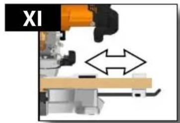
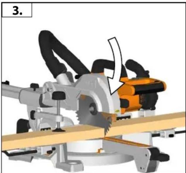
d) Push the saw through the workpiece. Do not pull the saw through the workpiece. To make a cut, raise the saw head and pull it out over the workpiece without cutting, start the motor, press the saw head down and push the saw through the workpiece. Cutting on the pull stroke is likely to cause the saw blade to climb on top of the workpiece and violently throw the blade assembly towards the operator.
e) Never cross your hand over the intended line of cutting either in front or behind the saw blade. Supporting the workpiece "cross handed" i.e. holding the workpiece to the right of the saw blade with your left hand or vice versa is very dangerous.
f) Do not reach behind the fence with either hand closer than 100 mm from either side of the saw blade, to remove wood scraps, or for any other reason while the blade is spinning. The proximity of the spinning saw blade to your hand may not be obvious and you may be seriously injured.
English
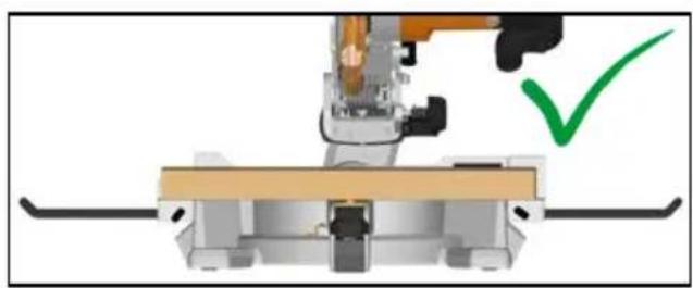
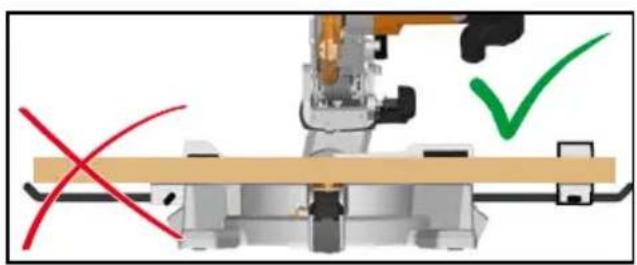
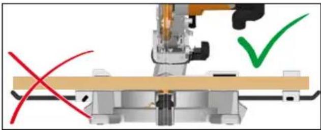
g) Inspect your workpiece before cutting. If the workpiece is bowed or warped, clamp it with the outside bowed face toward the fence. Always make certain that there is no gap between the workpiece, fence and table along the line of the cut. Bent or warped workpieces can twist or shift and may cause binding on the spinning saw blade while cutting. There should be no nails or foreign objects in the workpiece.
h) Do not use the saw until the table is clear of all tools, wood scraps, etc., except for the workpiece. Small debris or loose pieces of wood or other objects that contact the revolving blade can be thrown with high speed.
i) Cut only one workpiece at a time. Stacked multiple workpieces cannot be adequately clamped or braced and may bind on the blade or shift during cutting.
j) Ensure the mitre saw is mounted or placed on a level, firm work surface before use. A level and firm work surface reduces the risk of the mitre saw becoming unstable.
k) Plan your work. Every time you change the bevel or mitre angle setting, make sure the adjustable fence is set correctly to support the workpiece and will not interfere with the blade or the guarding system. Without turning the tool "ON" and with no workpiece on the table, move the saw blade through a complete simulated cut to assure there will be no interference or danger of cutting the fence.
I) Provide adequate support such as table extensions, saw horses, etc. for a workpiece that is wider or longer than the table top. Workpieces longer or wider than the mitre saw table can tip if not securely supported. If the cut-off piece or workpiece tips, it can lift the lower guard or be thrown by the spinning blade.
m) Do not use another person as a substitute for a table extension or as additional support. Unstable support for the workpiece can cause the blade to bind or the workpiece to shift during the cutting operation pulling you and the helper into the spinning blade.
n) The cut-off piece must not be jammed or pressed by any means against the spinning saw blade. If confined, i.e. using length stops, the cut-off piece could get wedged against the blade and thrown violently.
o) Always use a clamp or a fixture designed to properly support round material such as rods or tubing. Rods have a tendency to roll while being cut, causing the blade to "bite" and pull the work with your hand into the blade.
p) Let the blade reach full speed before contacting the workpiece. This will reduce the risk of the workpiece being thrown.
q) If the workpiece or blade becomes jammed, turn the mitre saw off. Wait for all moving parts to stop and disconnect the plug from the power source and/or remove the battery pack. Then work to free the jammed material.
Continued sawing with a jammed workpiece could cause loss of control or damage to the mitre saw.
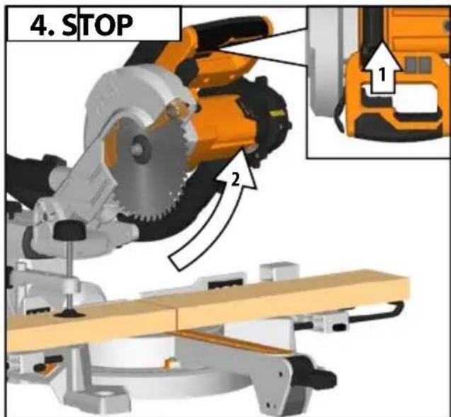
r) After finishing the cut, release the switch, hold the saw head down and wait for the blade to stop before removing the cut-off piece. Reaching with your hand near the coasting blade is dangerous.
s) Hold the handle firmly when making an incomplete cut or when releasing the switch before the saw head is completely in the down position. The braking action of the saw may cause the saw head to be suddenly pulled downward, causing a risk of injury.
WOOD CUTTING BLADE SAFETY WARNINGS
Please read the manual and instructions carefully before using the saw blade and the machine.
The machine must be in good condition, the spindle without deformation and vibration.
Do not use the saw without the guards in position, keep guards in good working order and properly maintained.
Ensure the operator is adequately trained in safety precautions, adjustment, and operation of the machine.
Always wear goggles and ear protection when using the machine. It is recommended to wear gloves, sturdy non-slip shoes and apron.
Before using any accessory, consult the instruction manual. The improper use of an accessory can cause damage and increase the potential for injury.
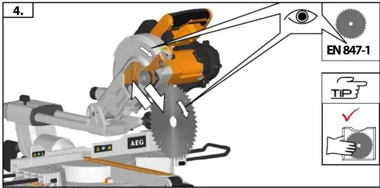
Use only blades specified in this manual, complying with EN 847-1.
Observe the maximum speed marked on the saw blade. Ensure the speed marked on the saw blade is at least equal to the speed marked on the saw.
Always use blades with correct size and shape of arbour holes. Blades that do not match the mounting hardware of the saw will run eccentrically, causing loss of control.
Do not use blades of larger or smaller diameter other than recommended. Do not use any spacers to make the blade fit onto the spindle.
Check the tips of the saw blade for damage or abnormal appearance before each use. Tips that are damaged or loose can become flying objects in use and increase the chance of personal injury.
Do not use cracked or distorted saw blades. Do not use saw blades which are damaged or deformed
Scrap the saw blade if damaged, deformed, distorted or cracked, repairing is not permitted.
Do not use HSS blades.
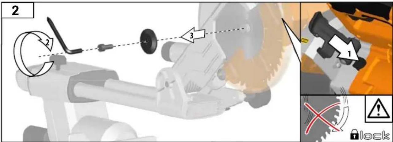
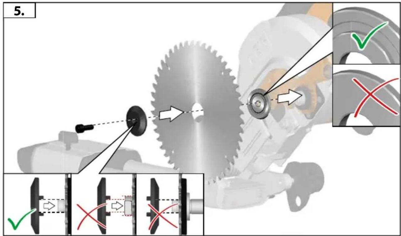
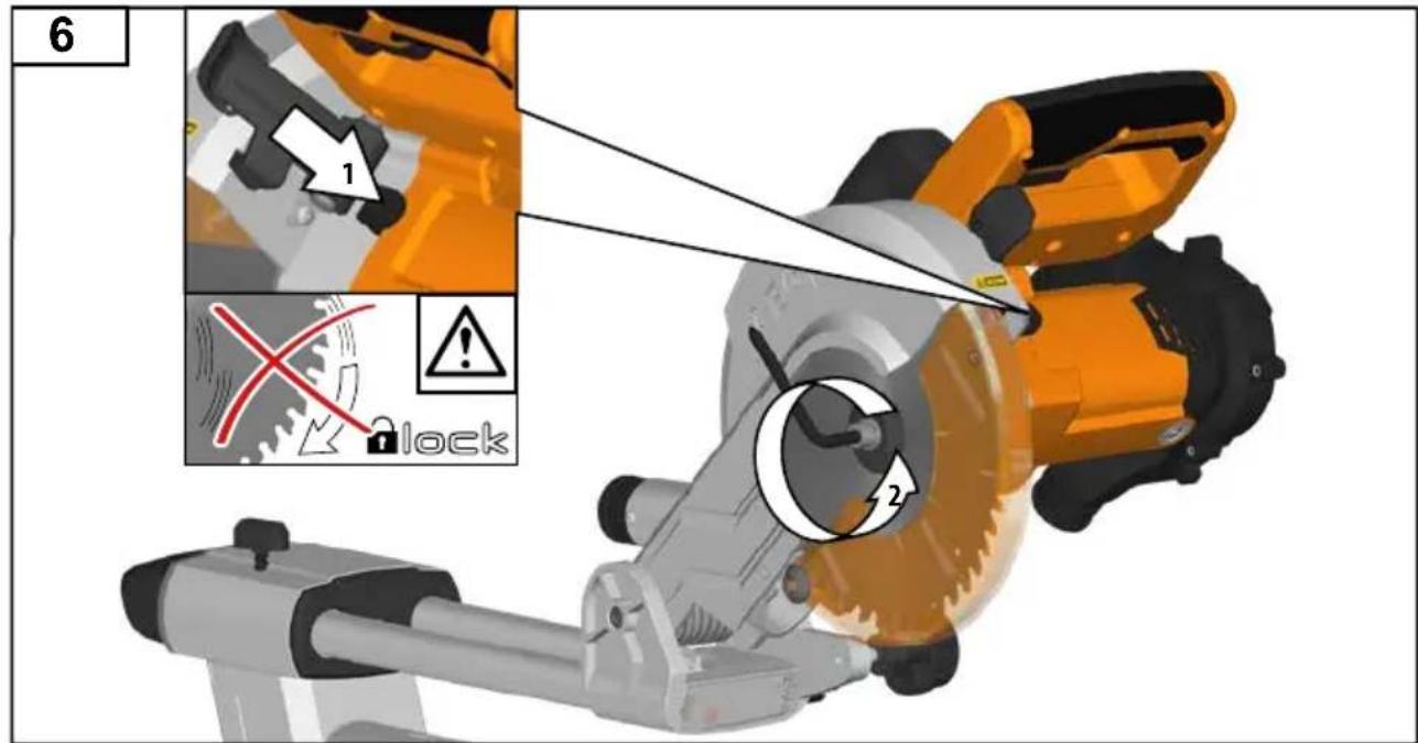
Ensure the saw blade is mounted correctly, tighten the arbor nut securely before use (tightening torque approx. 12 Nm).
Fastening screw and nuts shall be tightened using the appropriate spanner, etc.
Extension of the spanner or tightening using hammer blows is not permitted.
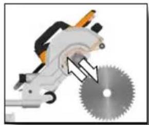
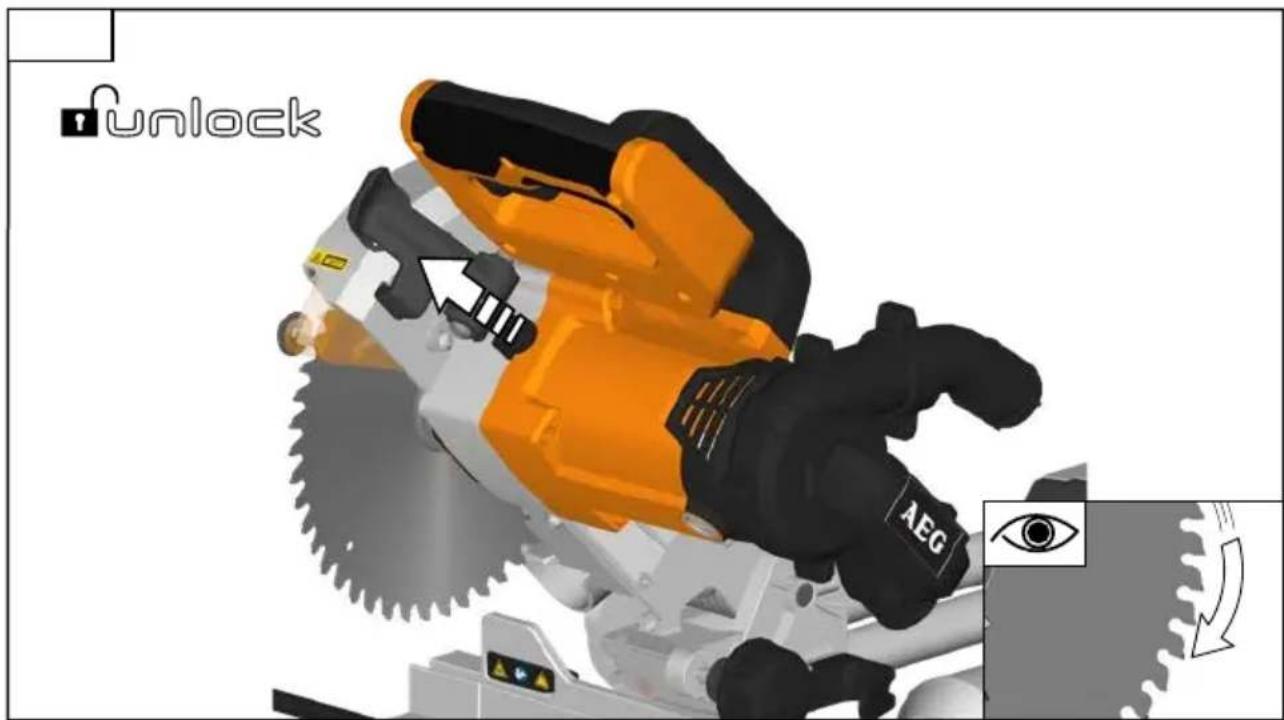
Make sure the blade and flanges are clean and the recessed sides of the collar are against the blade.
Make sure the blade rotates in the correct direction.
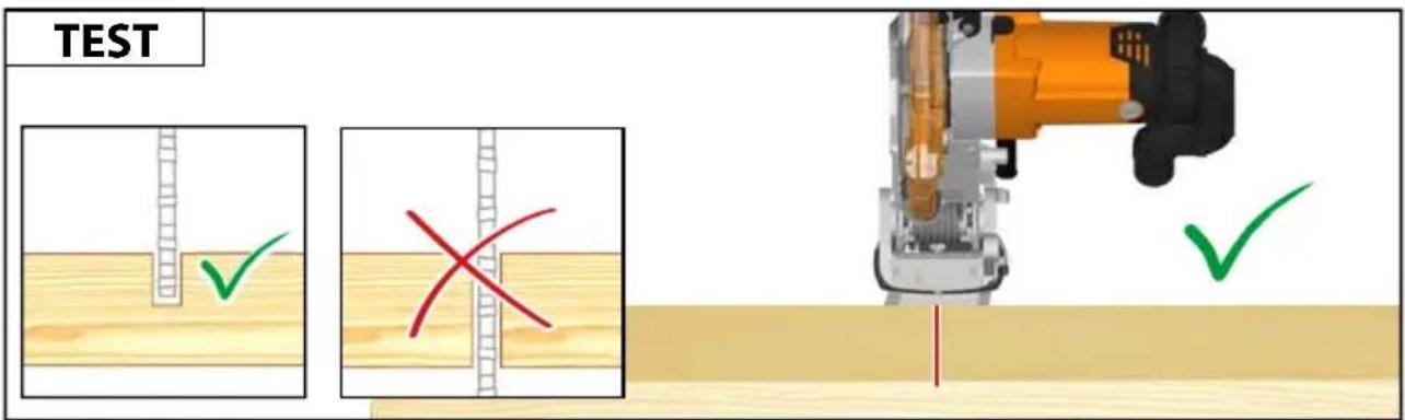
Before work, make a dummy cut without the motor turned on so the position of the blade, operation of the guards with respect to other machine parts and workpiece may be checked.
Never leave the machine unattended.
Do not apply lubricants on the blade when it is running.
Never perform any cleaning or maintenance work when the machine is still running and the head is not in the rest position.
Never attempt to stop a machine in motion rapidly by jamming a tool or other means against the blade, serious accidents can be caused unintentionally in this way.
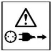
Disconnect the saw from the mains supply or remove battery pack before changing blades or carrying out maintenance.
English


Pay attention to blade packing and unpacking, it is easy to be injured by the sharp blade tips.
Use a blade holder or wear gloves when handling a saw blade.
Keep and store the blade in original packaging or other suitable packaging, keep in dry conditions and away from chemicals which may damage the blade.
ADDITIONAL SAFETY AND WORKING INSTRUCTIONS
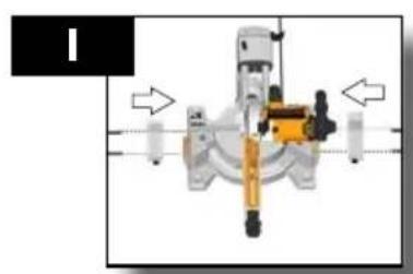
Always clamp the workpiece safely and securely.
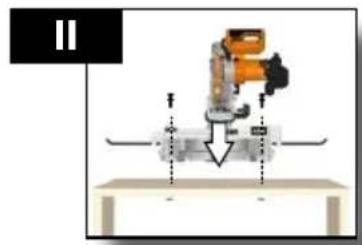
Ensure that the machine is always stable and secure (e.g. fixed to a bench).
Wear ear protectors. Exposure to noise can cause hearing loss.
Always wear safety goggles when using the machine. It is recommended to wear gloves for handling blades and rough material, as well as sturdy non-slip shoes which also protect the feet from workpieces that may fall from the cutting area.
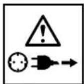
Always make sure the power plug has been removed from the mains power source before making adjustments, lubricating or when doing any maintenance on the product.
Only plug-in when machine is switched off.
Never reach into the area near the blade, unless the blade has completely stopped.
Before use, thoroughly check the tool for any damage or material fatigue. Repairs should only be carried out by authorised Service Agents.
Always use the guards on the machine. Do not use the machine if the guards are not in place and working correctly.
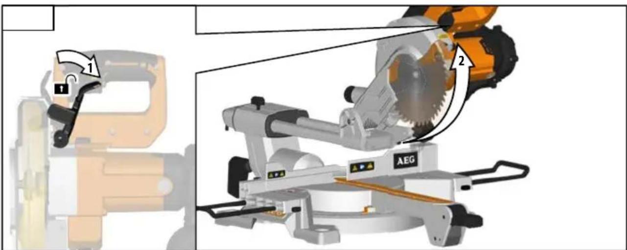
The lower blade guard should only open when the blade is lowered to the workpiece and must always be able to move freely and close automatically..
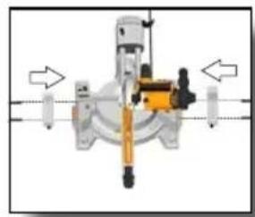
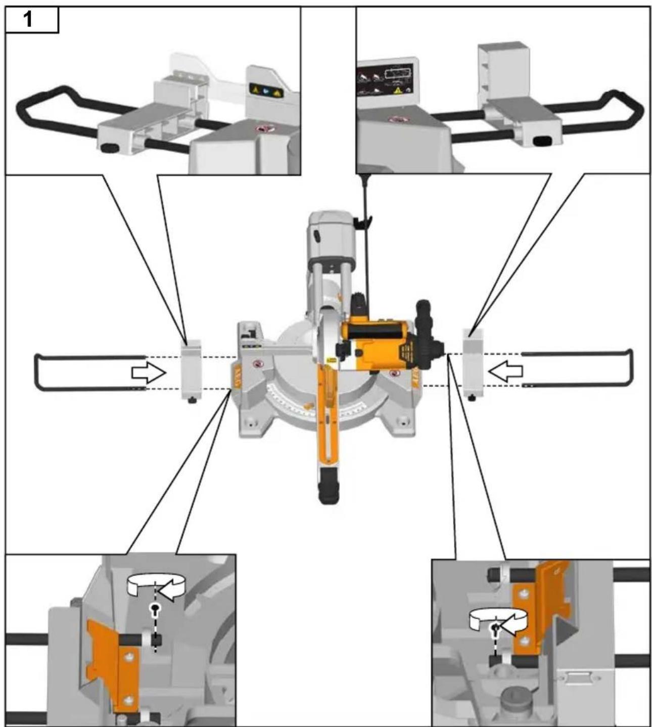
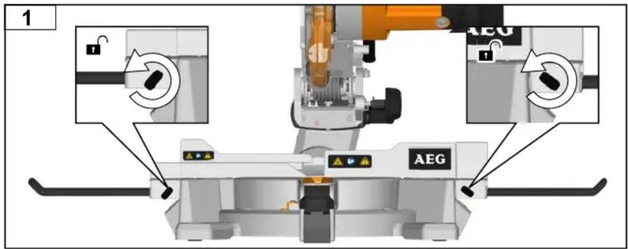
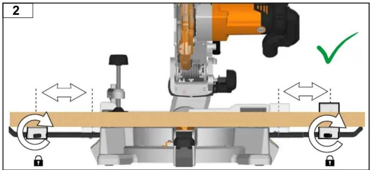
Always fix and use extension bar holders for workpiece support during operation.
Never alter of modify the saw or its function. Your safety may be compromised.
Do not use saw blades which are cracked, damaged, or deformed.
Do not use saw blades made of high-speed steel.
Only use saw blades which are sharp. Replace blunt blades with a new replacement.
Always use blades with correct size and shape of arbour holes.
Blades that do not match the mounting hardware of the saw will run eccentrically, causing loss of control.
Use only woodworking blades specified in this manual, which comply with EN 847-1.
Do not use any flanges, washers, and nuts to secure the saw blade other than those supplied or indicated in the instruction manual.
It is necessary to select a saw blade which is suitable for the material being cut. Never use the product to cut materials other than those specified in the intended use section in this manual.
It is important to avoid overheating the blade and melting the plastic workpiece when cutting.
It is essential to adhere to the maximum speed specified on the saw blade. only use saw blade that are marked with a speed equal or higher than the speed marked on the tool.
Replace the table insert when worn or damaged.
Before work, make a dummy cut without the motor turned on so the position of the blade, operation of the guards with respect to other machine parts, and workpiece may be checked.
When performing mitre, bevel or compound mitre cuts, adjust the sliding fence to ensure the correct clearance from the blade.
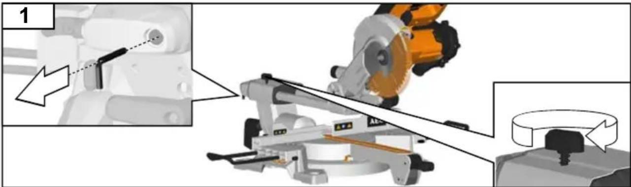
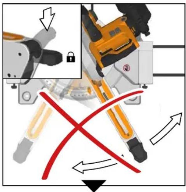
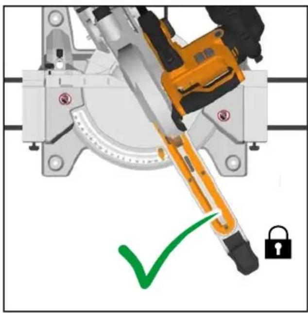
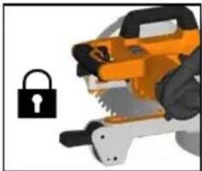
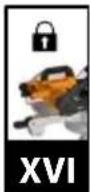
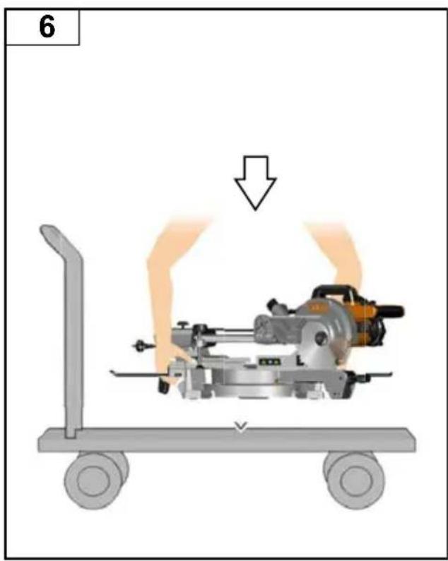
The bracket stop must always be engaged when transporting the product.
Keep the floor area free of loose material e.g. chips and cut-offs.
Refrain from removing any cut-offs or other parts of the workpiece from the cutting area whilst the machine is running and the saw head is not in the rest position.
Long workpieces must be adequately supported. The working area of the saw includes the whole extent of the workpiece. The operator should secure this area from accidental contact from other persons or objects which may move the workpiece during operation.
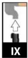
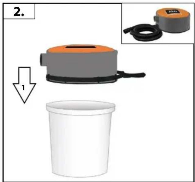
The dust produced when using this tool may be harmful to health. Do not inhale the dust. Use a dust absorption system and wear a suitable dust protection mask. Remove deposited dust thoroughly, e.g. with a vacuum cleaner.
Do not replace the LED or laser with a different type. Any repairs must only be carried out by the manufacturer or authorised service agent.
A power spike causes voltage fluctuations and may affect other electrical products in the same power line. Connect the product to a power supply with an impedance equal to 0.3 to minimize voltage fluctuations. Contact your electric power supplier for further clarification.
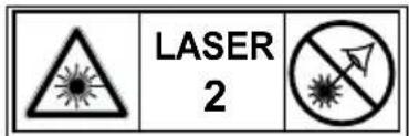
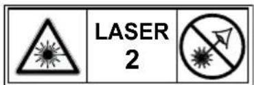
SAFETY WARNINGS LASER
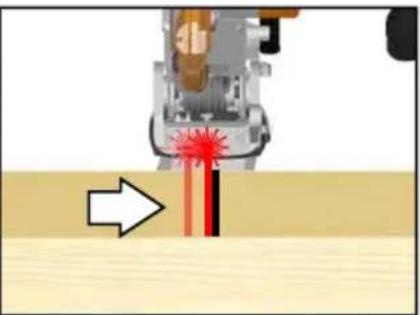
The laser radiation used in this saw is Class II with maximum P≤1mW and λ:650nm wavelengths. Do not view directly with optical instruments. Failure to comply with the rules could result in serious personal injury.
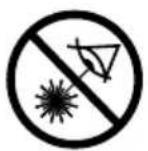
Do not stare into beam during operation.
Do not project the laser beam directly into the eyes of others. Serious eye injury could result.
Do not place the laser in a position that may cause anyone to stare into the laser beam intentionally or unintentionally.
Do not use optical tools to view the laser beam.
Do not operate the laser around children or allow children to operate the laser.
Do not attempt to repair the laser device by yourself.
Do not attempt to change any parts of the laser device by yourself.
Any repairs must only be carried out by the manufacturer or authorised service agent.
Do not replace the installed laser with a different type.
SPECIFIED CONDITIONS OF USE
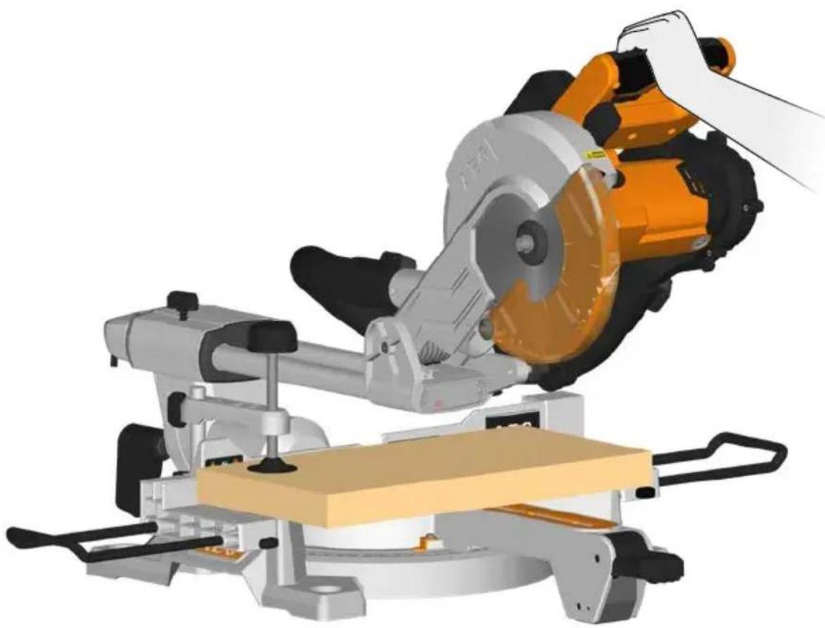
The slide compound mitre saw is intended for sawing solid and bonded wood with or without glued veneer, plastics, and materials similar to wood.
The slide compound mitre saw is intended to be used only by adult operators who have read the instruction manual and understand the risks and hazards.
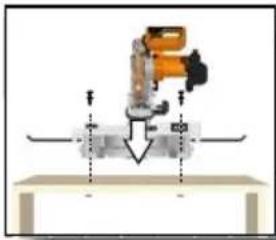
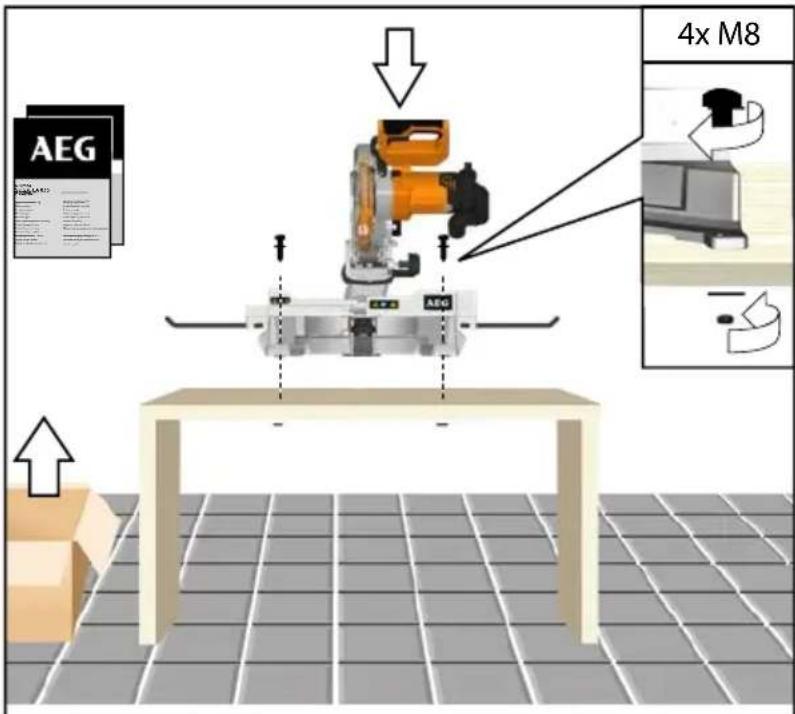
The slide compound mitre saw is designed to be fixed at the base to a solid bench top. If the base is not securely fixed, the whole machine may move during cutting operations, which increases the possibility of serious personal injury.
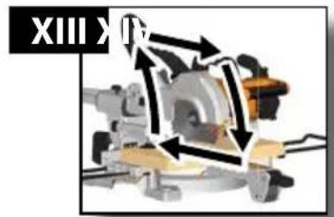
The slide compound mitre saw is designed make bevel and mitre cuts. The capacities for the various cuts are provided in the product specifications in this manual.
English
The slide compound mitre saw is to be used in dry conditions, with excellent ambient lighting and adequate ventilation.
The slide compound mitre saw is intended for consumer use and should only be used as described above and is not intended for any other purpose.
RESIDUAL RISK
Even when the slide compound mitre saw is used as prescribed, it is still impossible to completely eliminate certain residual risk factors. The following hazards may arise and the operator should pay special attention to avoid the following:
- Risk of contact with uncovered parts of the rotating saw blade.
- Kick-back of work pieces or parts of work pieces due to improper adjustment or handling.
- Catapulting of faulty carbide tips from the saw blade.
- Damage to the respiratory system.
NOTE: Wear respiratory protection masks containing filters appropriate to the materials being worked.
Ensure adequate workplace ventilation. Do not eat, drink or smoke in the work area.
Damage to hearing if effective hearing protection is not worn.
WARNING
Dust from certain paintsm coatings and materials may cause irritation or allergic reactions to the respiratory system. Dust from wood such as oak, beech, MDF and others are carcinogenic. Material containing asbestos should only ever be worked or processed by qualified specialist operators.
WARNING
Injuries may be caused, or aggravated, by prolonged use of a tool. When using any tool for prolonged periods, ensure you take regular breaks.
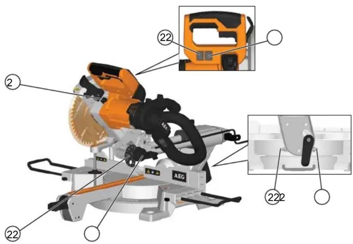
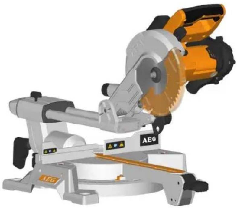
KNOW YOUR PRODUCT
See page A.
| 1. Handle, insulated gripping surface | 22. 45° bevel angle adjustment screw |
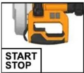
| 2. Switch trigger | 23. 90° bevel angle adjustment screw |
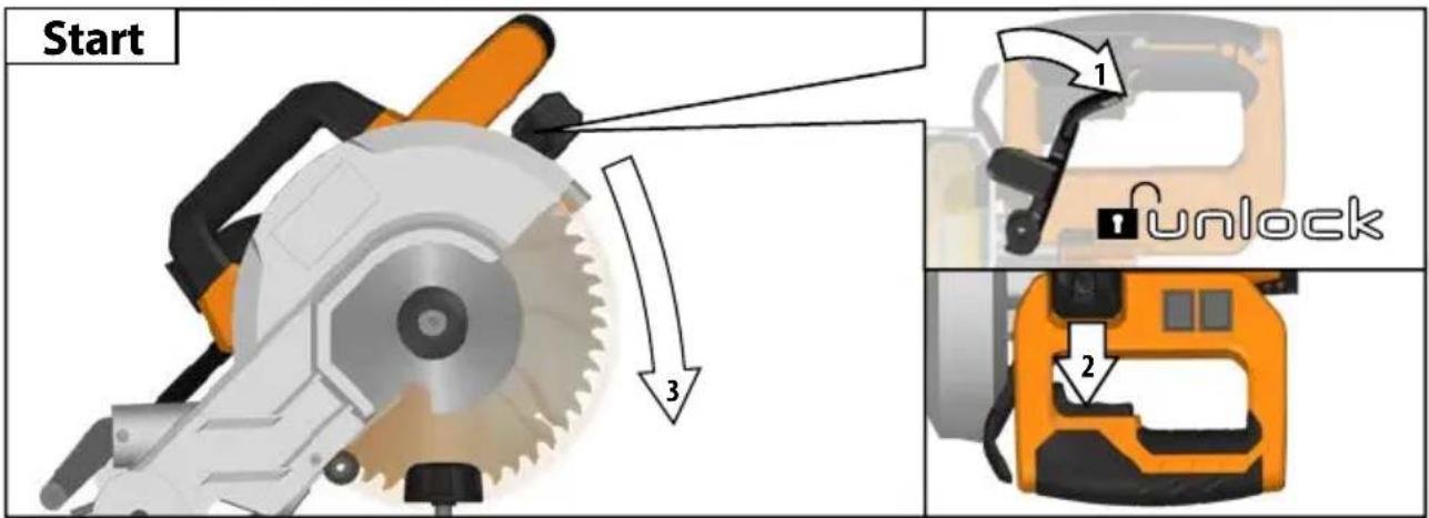
| 3. Safety lock lever |
| 4. Outer flange | 24. LED switch |
| 5. Saw blade | 25. Laser switch |
| 6. Lower guard | 26. Spindle lock button |
| 7. Fixed fence | 27. Cutting depth adjustment plate |
| 8. Kerf plate |
| 9. Turn table lock handle | 28. Cutting depth adjustment knob |
- Top handle
- Upper guard
- Dust chute
- Linear rod stop knob
- Clamp
- Bevel angle lock lever
- Sliding fence
- Workpiece holder
- Extension bar
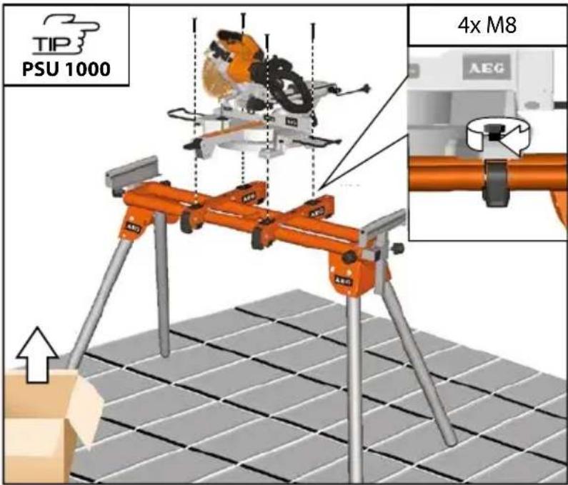
- Mounting holes x4
- Turntable
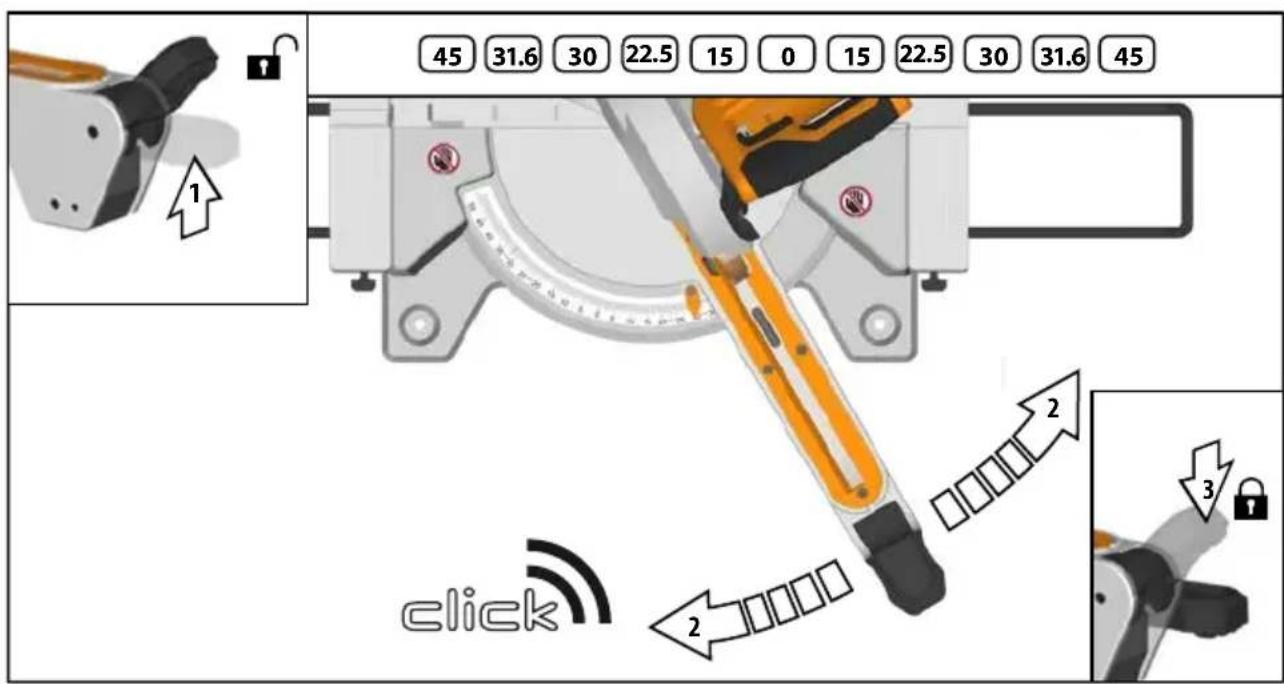
- Mitre scale
REPLACEMENT LIST
- PS 216 L: Mitresaw EN 847-1/ø216 x ø30 x 2,4 / 48T / HW / n max. 7000 min-1 (Page A: No. 5)
- PS 254 L: Mitresaw EN 847-1/ø254 x ø30 x 2,6 / 48T / HW / n max. 7400 min-1 (Page A: No. 5)
- KKerf plate (Page A: No. 8)
MAINS CONNECTION
Connect only to single-phase AC system voltage as indicated on the rating plate. It is also possible to connect to sockets without an earthing contact as the design conforms to safety class II.
Appliances used at many different locations including wet room and open air must be connected via a residual current device (FI, RCD, PRCD) of 30mA or less.
Only plug-in when machine is switched off.
Keep mains lead clear from working range of the machine. Always lead the cable away behind you.
Before use check machine, cable, and plug for any damages or material fatigue. Repairs should only be carried out by authorised Service Agents.
A power spike causes voltage fluctuations and may affect other electrical products in the same power line. Connect the product to a power supply with an impedance equal to 0.3 to minimize voltage fluctuations.
Contact your electric power supplier for further clarification.
MAINTENANCE
Do not modify this saw in any way or use accessories not approved by the manufacturer. Your safety and that of others may be compromised.
Do not use the saw if any switches, guards or other function of this saw does not work as it is intended to. Return to an authorised service centre for professional repair or adjustment.
Do not make any adjustments whilst the saw blade is in motion.
Always make sure the power plug has been removed from the mains power source before making adjustments, lubricating or when doing any maintenance on the product.
Before and after each use, check your saw for damage or broken parts and keep it in top working condition by replacing parts immediately with spares approved by the manufacturer.
The blade is very hot after use, wear gloves or allow to cool before maintenance or cleaning procedures.
Clean out accumulated dust using a brush or vacuum cleaner. Do not use compressed air.
To assure safety and reliability, all repairs, including changing brushes, should be performed by an authorised service centre.
Clean tool and guarding system with dry cloth.
The ventilation slots of the machine must be kept clear at all times.
If the replacement of the supply cord is necessary, this has to be done by the manufacturer or his agent in order to avoid a safety hazard.
Use only AEG accessories and spare parts. Should components need to be replaced which have not been described, please contact one of our AEG service agents (see our list of guarantee/service addresses).
If needed, an exploded view of the tool can be ordered. Please state the Article No. as well as the machine type printed on the label and order the drawing at your local service agents or directly at: Techtronic Industries GmbH, Max-Eyth-Straße 10, 71364 Winnenden, Germany.
English
We declare under our sole responsibility that the product described under "Technical Data" fulfills all the relevant provisions of the directives
2011/65/EU (RoHS)
2006/42/EC
2014/30/EU
and the following harmonized standards have been used.
EN 62841-1:2015
EN 62841-3-9:2015+A11:2017
EN 55014-1:2017
EN 55014-2:2015
EN 61000-3-2:2014
EN 61000-3-11:2000
EN IEC 63000:2018


Winnenden, 2019-03-08
Alexander Krug / Managing Director
Authorized to compile the technical file
Techtronic Industries GmbH
Max-Eyth-Straße 10, 71364 Winnenden, Germany
SYMBOLS

CAUTION! WARNING! DANGER!

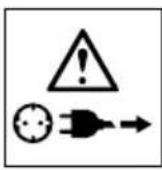
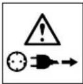
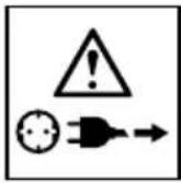
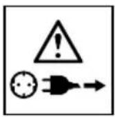
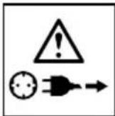
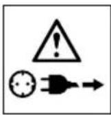
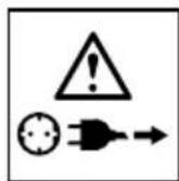
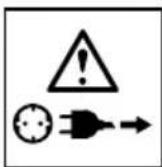
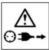
Always disconnect the plug from the socket before carrying out any work on the machine.

WARNING-To reduce the risk of injury, user must read instruction manual!

Always wear goggles when using the machine.

Wear ear protectors!

Wear gloves!

Always keep hands away from the path of the saw blade.

This tool is only suitable for indoor use. Never expose tool to rain.

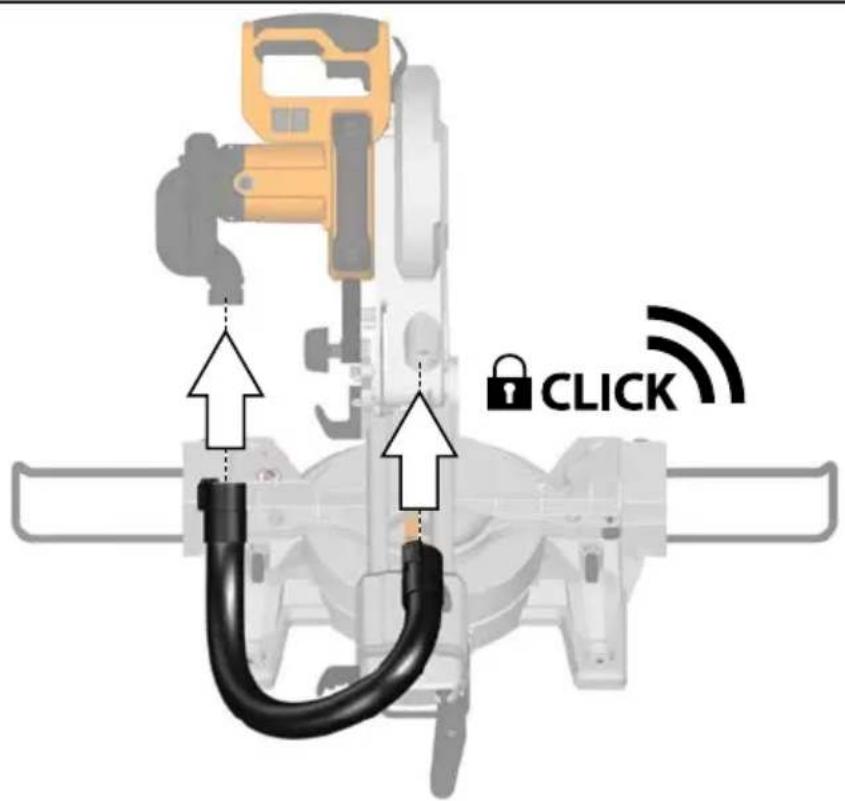
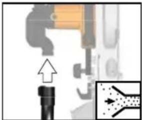
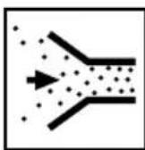
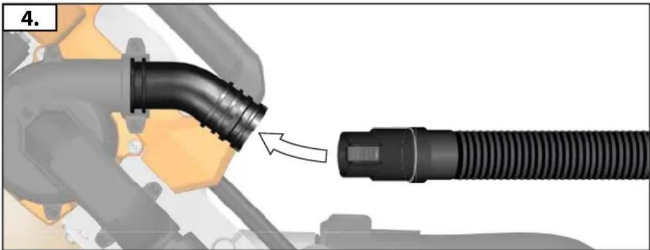
Dust chute connection port

Cut wood only.

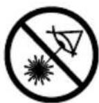
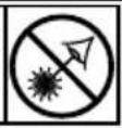
Do not stare into beam.
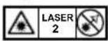
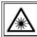
This product corresponds to the laser class 2 in accordance with EN 60825-1:2014.
Saw blade dia. x hole dia

Rotation direction

Blade teeth

Width of cut

No-load speed

Voltage

AC Current

Class II tool. Tool in which protection against electric shock does not rely on basic insulation only, but in which additional safety precautions, such as double insulation or reinforced insulation, are provided.
There being no provision for protective earthing or reliance upon installation conditions.

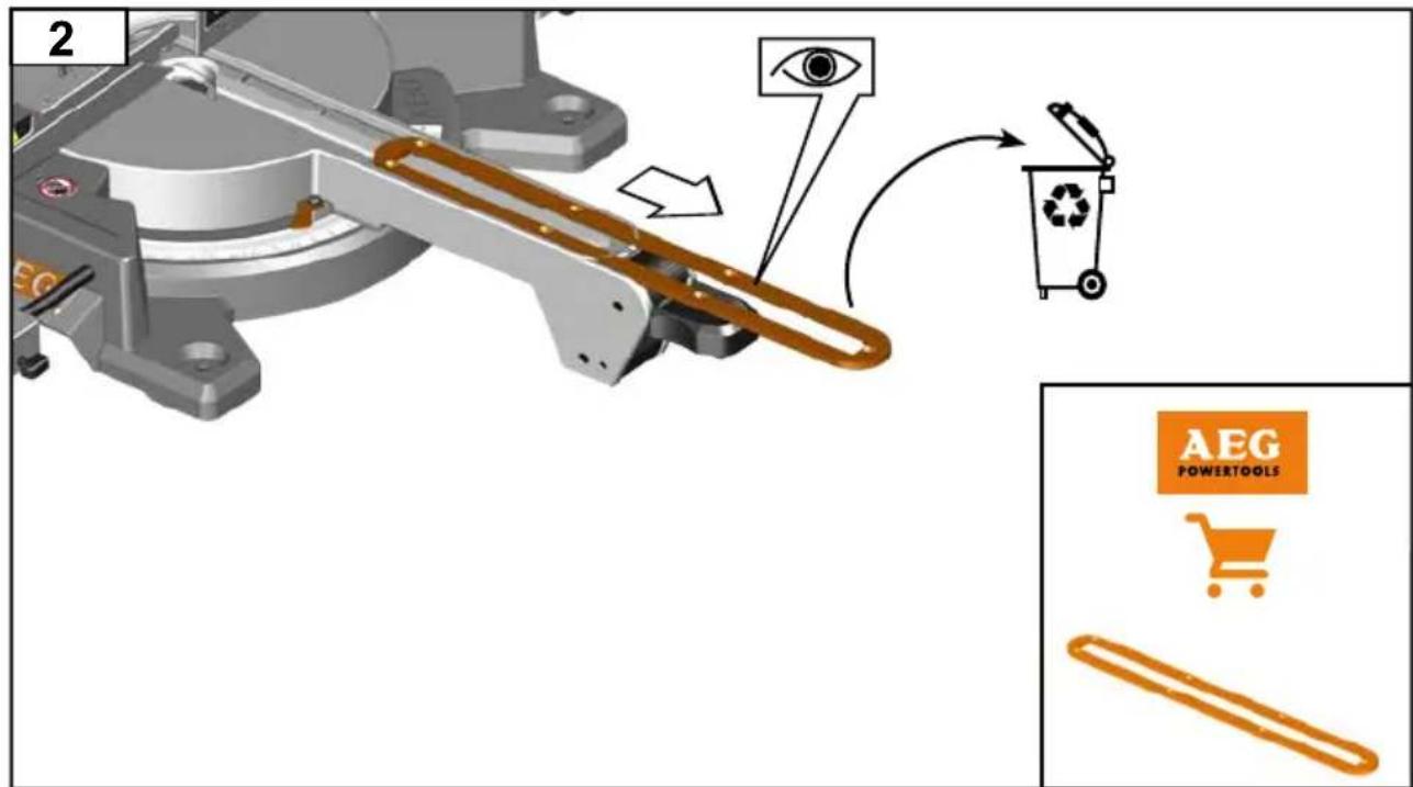
Do not dispose of electric tools together with household waste material. Electric tools and electronic equipment that have reached the end of their life must be collected separately and returned to an environmentally compatible recycling facility. Check with your local authority or retailer for recycling advice and collection point.

European Conformity Mark

Ukraine Conformity Mark

EurAsian Conformity Mark
English
MACHEN SIE SICH MIT IHREM PRODUKT VERTRAUT.
Siehe Seite A.
Alexander Krug / Managing Director
Max-Eyth-Straße 10, 71364 Winnenden, Germany


SYMBOLE

CONNAÎTRE SON PRODUIT
Voir page A.
Alexander Krug / Managing Director
Max-Eyth-Straße 10, 71364 Winnenden, Germany
SYMBOLES

ATTENTION! AVERTISSEMENT! DANGER!

Alexander Krug / Managing Director
Max-Eyth-Straße 10, 71364 Winnenden, Germany

SIMBOLI

ATTENZIONE! AVVERTENZA! PERICOLO!

Alexander Krug / Managing Director
Max-Eyth-Straße 10, 71364 Winnenden, Germany

SÍMBOLOS

Alexander Krug / Managing Director
Max-Eyth-Straße 10, 71364 Winnenden, Germany


SYMBOLE

ATENÇÃO! PERIGO!

MAAK U VERTROUWD MET UW PRODUCT
Zie pagina A.
Alexander Krug / Managing Director
Max-Eyth-Straße 10, 71364 Winnenden, Germany


SYMBOLEN

OPGELET! WAARSCHUWING! GEVAAR!

LÆR DIT PRODUKT AT KENDE
Se side A.
Alexander Krug / Managing Director
Max-Eyth-Straße 10, 71364 Winnenden, Germany


SYMBOLER

VIGTIGT! ADVARSEL! FARE!

Alexander Krug / Managing Director
Max-Eyth-Straße 10, 71364 Winnenden, Germany
SYMBOLER

OBS! ADVARSEL! FARE!

GÖR DIG FÖRTROGEN MED DIN PRODUKT
Se sidan A.
Alexander Krug / Managing Director
Max-Eyth-Straße 10, 71364 Winnenden, Germany
SYMBOLER

OBSERVERA! WARNING! FARA!

Max-Eyth-Straße 10, 71364 Winnenden, Germany
SYMBOLIT

HUOMIO! VAROITUS! VAARA!

Alexander Krug / Managing Director
Max-Eyth-Straße 10, 71364 Winnenden, Germany
ΣΥΜΒΟΛΑ

Alexander Krug / Managing Director
Max-Eyth-Straße 10, 71364 Winnenden, Germany
SEMBOLLER

DİKKAT! UYARI! TEHLİKE!

DALŠÍ BEZPEČNOSTNÍ A PRACOVNÍ POKYNY
Max-Eyth-Straße 10, 71364 Winnenden, Germany
SYMBOLY

POZOR! VAROVÁN! NEBEZPEČÍ!

ĎALŠIE BEZPEČNOSTNÉ A PRACOVNÉ POKYNY
Max-Eyth-Straße 10, 71364 Winnenden, Germany
SYMBOLY

POZOR! NEBEZPEČENSTVO!

Alexander Krug / Managing Director
Max-Eyth-Straße 10, 71364 Winnenden, Germany
Polski
SYMBOLE

Alexander Krug / Managing Director
Max-Eyth-Straße 10, 71364 Winnenden, Germany
SZIMBÓLUMOK

FIGYELEM! FIGYELMEZTETÉS! VESZÉLY!

UPORABA V SKLADU Z NAMEMBNOSTJO
Alexander Krug / Managing Director
Max-Eyth-Straße 10, 71364 Winnenden, Germany
SIMBOLI

POZOR! OPOZORILO! NEVARNO!

OSTALE SIGURNOSNE I RADNE UPUTE
Obradak uvijek stežite sigurno.
Max-Eyth-Straße 10, 71364 Winnenden, Germany
SIMBOLI

PAŽNJA! UPOZORENIE! OPASNOST!

Prije radova na stroju izvući utikač iz utičnice.

UPOZORENIE-Kako biste smanjili opasnost od ozljeda, pročitajte upute za uporabu!

Max-Eyth-Straße 10, 71364 Winnenden, Germany
SIMBOLI

UZMANİBU! BİSTAMI!

Pirms jebkādiem darbiem, kas attiecas uz mašinas apkopi, mašinu noteikti vajag atvienot no kontaktligzdas.

Max-Eyth-Straße 10, 71364 Winnenden, Germany
SIMBOLIAI

DĖMESIO! JSPĖJIMAS! PAVOJUS!

EDASISED OHUTUS- JA TÖÖJUHISED
SPETSIAALSED TURVAJUHISED LASER
Alexander Krug / Managing Director
Max-Eyth-Straße 10, 71364 Winnenden, Germany
SÜMBOLID

ETTEVAATUST! TÄHELEPANU! OHUD!

Alexander Krug / Managing Director
Max-Eyth-Straße 10, 71364 Winnenden, Germany
СИМВОЛЫ

Alexander Krug / Managing Director
Max-Eyth-Straße 10, 71364 Winnenden, Germany
СИМВОЛИ

Alexander Krug / Managing Director
Max-Eyth-Straße 10, 71364 Winnenden, Germany
Română
SIMBOLURI

PERICOL! AVERTIZARE! ATENTIE!

Alexander Krug / Managing Director
Max-Eyth-Straße 10, 71364 Winnenden, Germany
СИМБОЛИ

ВНИМАНИЕ! ПРЕДУПРЕДУВАЊЕ! ОПАСНОСТ!

Alexander Krug / Managing Director
Max-Eyth-Straße 10, 71364 Winnenden, Germany
СИМВОЛИ