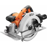
KS 662 - Jigsaw AEG - Free user manual and instructions
Find the device manual for free KS 662 AEG in PDF.

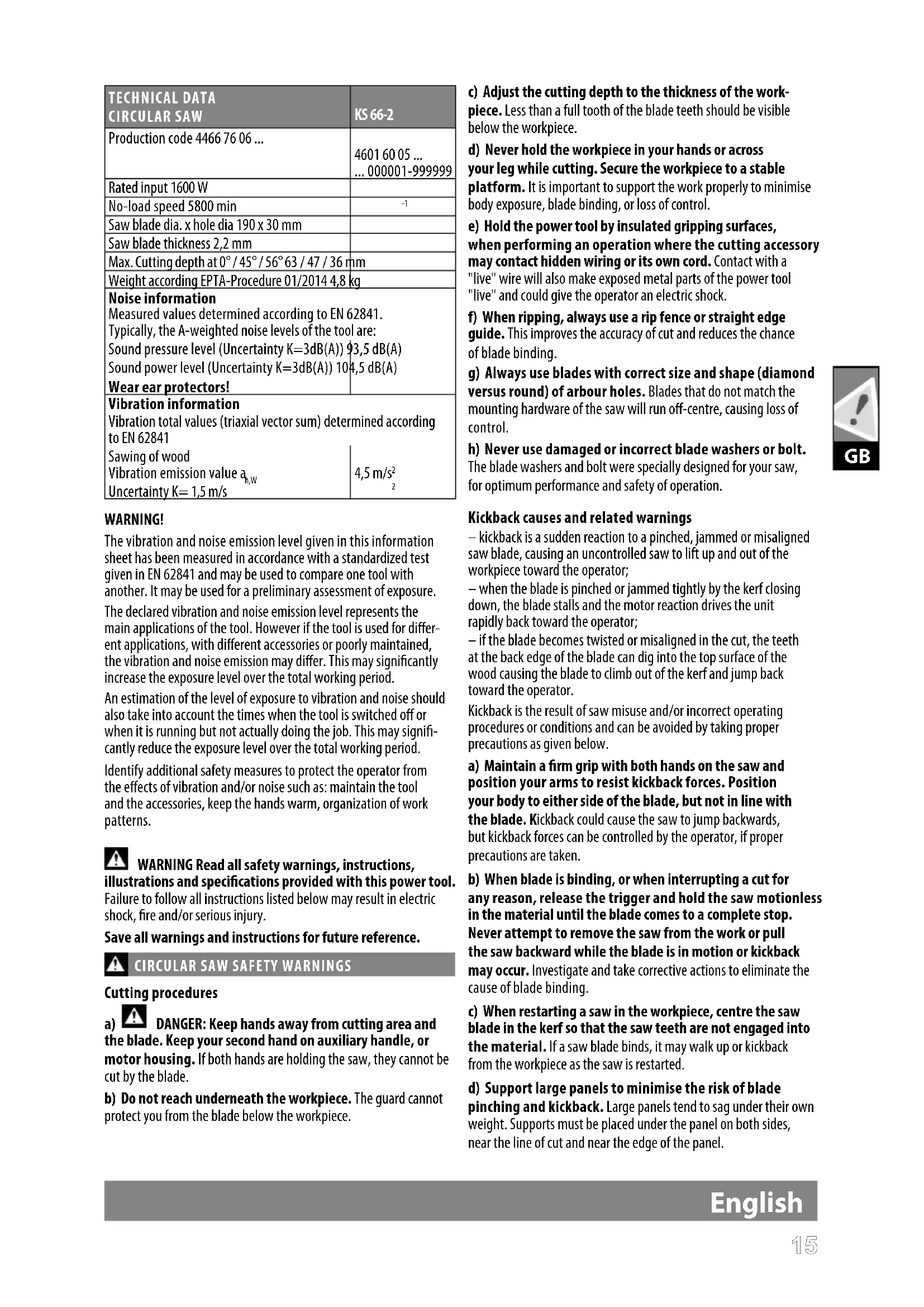


| Product Type | Circular Saw |
| Brand | AEG |
| Model | KS 66-2 |
| Rated power | 1600 W |
| No-load speed | 5800 rpm |
| Blade diameter | 190 mm |
| Blade bore | 30 mm |
| Blade thickness | 2.2 mm |
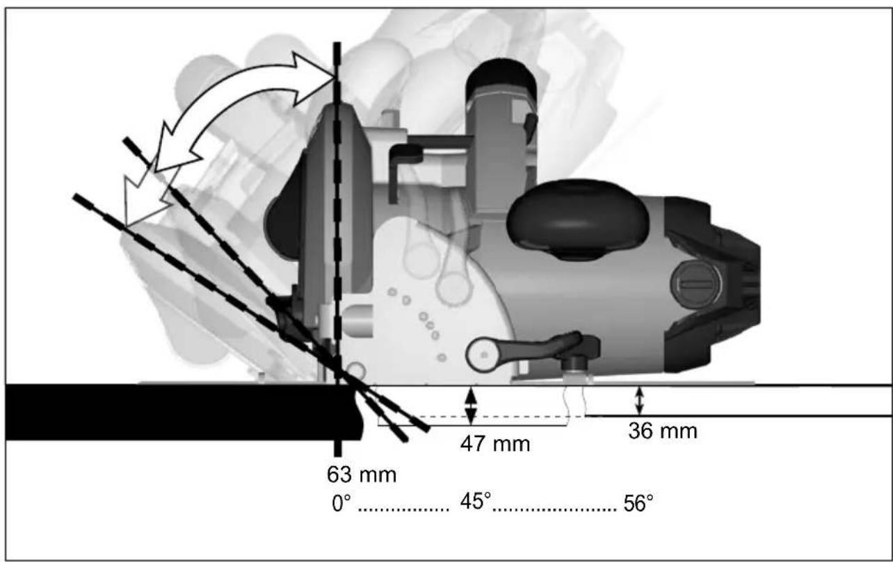
| Max. cutting depth at 0° | 63 mm |
| Max. cutting depth at 45° | 47 mm |
| Max. cutting depth at 56° | 36 mm |
| Weight (EPTA 01/2014) | 4.8 kg |
| Sound pressure level (K=3 dB(A)) | 93.5 dB(A) |
| Sound power level (K=3 dB(A)) | 104.5 dB(A) |
| Vibration emission value (wood) | 4.5 m/s² |
| Vibration uncertainty | 1.5 m/s² |
| Protection class | II (double insulation) |
| Power supply | Single-phase, mains voltage (see rating plate) |
| Main functions | Longitudinal cuts in wood, mitre cuts (0-56°), plunge cutting |
| Maintenance and cleaning | Unplug before maintenance; clean with a dry cloth; keep ventilation openings clean; remove accumulated sawdust |
| Safety | Lower guard, double insulation, safety switch, anti-kickback protection |
| Spare parts and repairability | Use only AEG parts; contact authorized service for cord replacement or other repairs |
| General information | Compliant with CE directives; declaration of conformity according to EN 62841; manual available in French |
Frequently Asked Questions - KS 662 AEG
User questions about KS 662 AEG
0 question about this device. Answer the ones you know or ask your own.
Ask a new question about this device
Download the instructions for your Jigsaw in PDF format for free! Find your manual KS 662 - AEG and take your electronic device back in hand. On this page are published all the documents necessary for the use of your device. KS 662 by AEG.
USER MANUAL KS 662 AEG
Original instructions
natural_image
3D rendering of a circular saw blade labeled AEG, shown in grayscale with no additional text or symbols.
natural_image
Mechanical gear assembly diagram showing cutting and rolling process (no text or symbols)
natural_image
Pure mechanical diagram showing a gear and blade assembly without any text, numbers, or symbols
natural_image
Mechanical component diagram showing a curved tool interacting with a surface, with no visible text or symbols.
natural_image
Close-up of a mechanical gear assembly with no visible text or symbols

natural_image
Close-up of a mechanical gear and blade assembly with no visible text or symbols

natural_image
Mechanical gear assembly diagram showing meshing gears and a cutting tool (no text or symbols)



natural_image
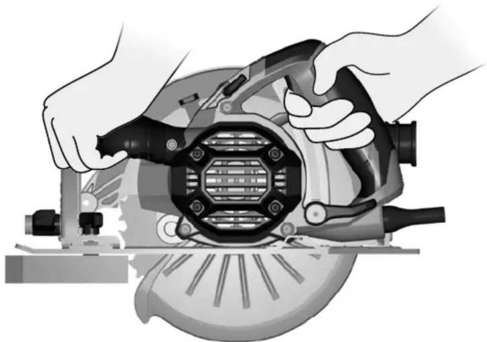
Illustration of hands operating a power cutter on a cutting board (no text or symbols visible)Insulated gripping surface



natural_image
Pure mechanical diagram showing a gear and conveyor system without any text, numbers, or symbols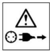
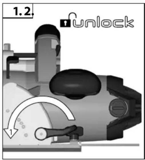
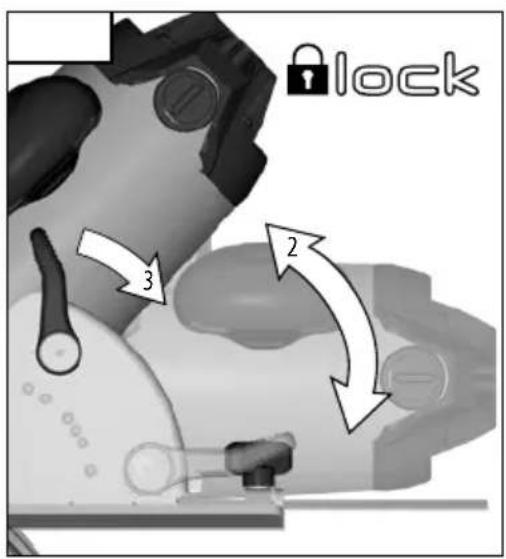
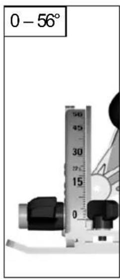
natural_image
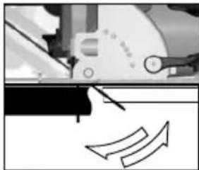
Mechanical assembly diagram showing a cutting tool interacting with a gear and directional arrows (no text or labels)
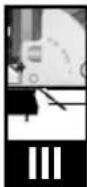
If a correction of the 90° angle of the guide-plate to the saw blade is necessary, use the correction screw.
natural_image
Mechanical assembly diagram showing a motor with three directional arrows labeled 1, 2, and 3 (no text or symbols beyond labels)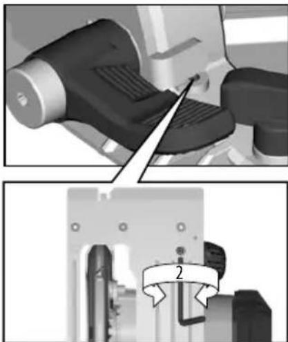
natural_image
Two-panel image showing a robotic arm and a mechanical component with a numbered label (2), no readable text or symbols present.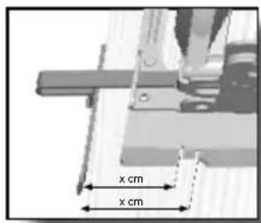
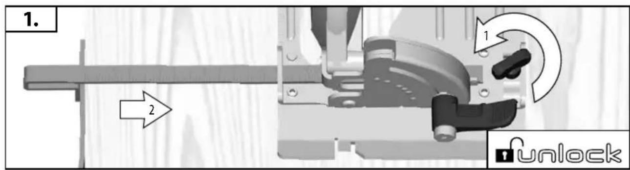
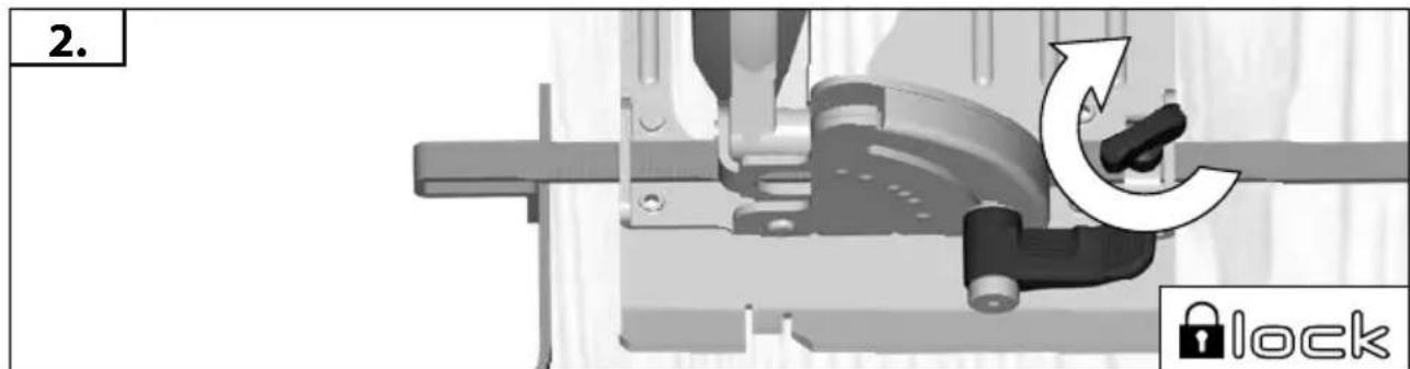
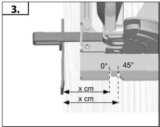
Carry out a test cut
natural_image
Mechanical device with curved components and a downward arrow indicating force or motion (no visible text or symbols)
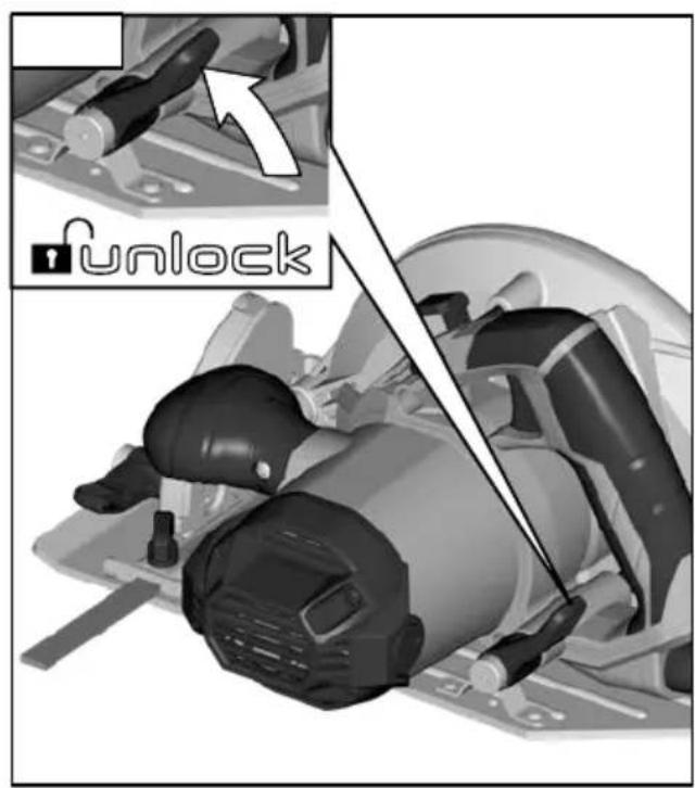
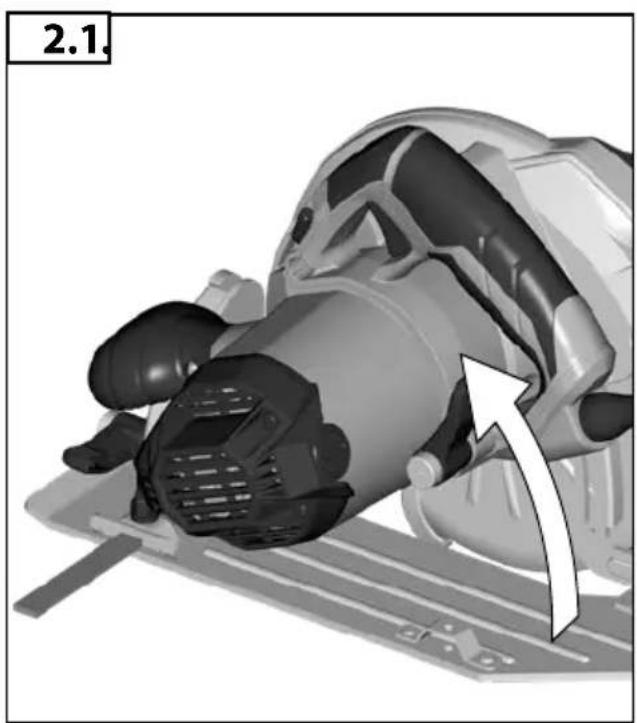
natural_image
3D rendered mechanical component with a white arrow indicating motion direction (no text or symbols)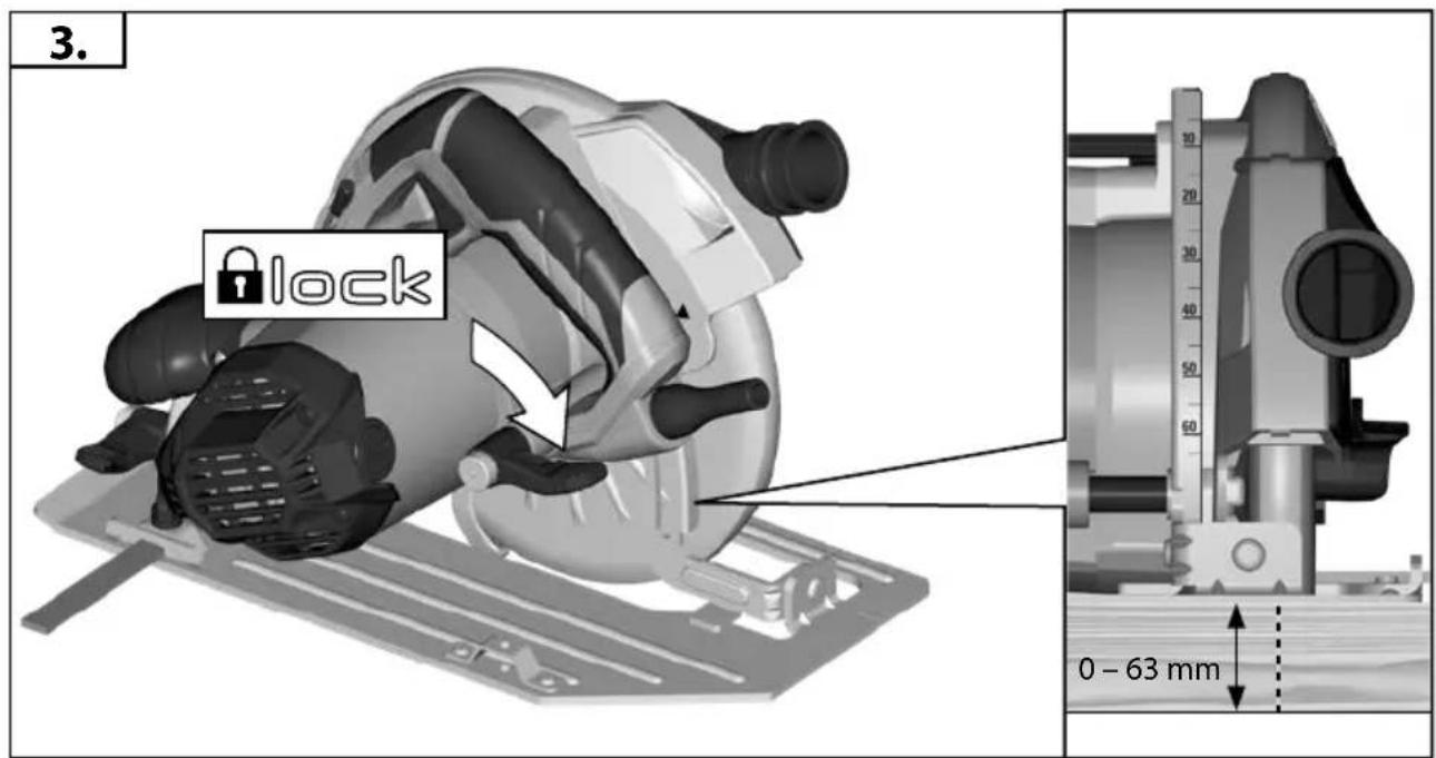
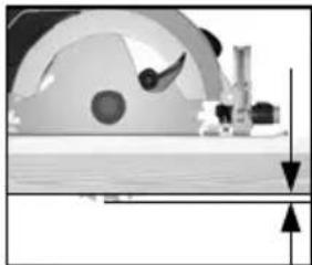
natural_image
Cross-sectional diagram of a mechanical assembly with no visible text or symbols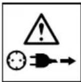
natural_image
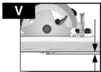
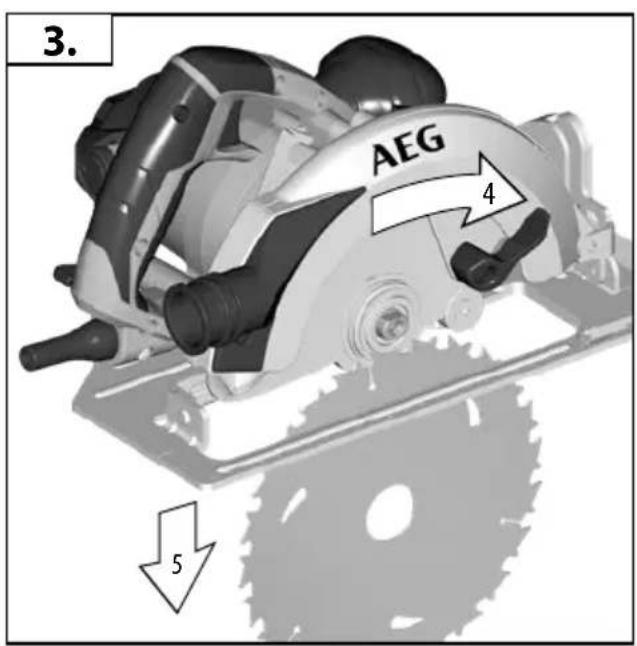
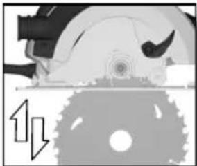
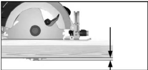
Diagram of a mechanical device with a circular component and directional arrows indicating motion or force (no text or symbols)Adjust the cutting depth to the thickness of the workpiece. Less than a full tooth of the blade teeth should be visible below the workpiece.
natural_image
Pure mechanical diagram showing a wheel and shaft assembly without any text, numbers, or symbolsnatural_image
Diagram of a particle flow through a channel with arrows indicating direction (no text or labels)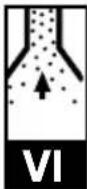







natural_image
Illustration of a mechanical device with a checkmark and a checkmark symbol (no text or labels)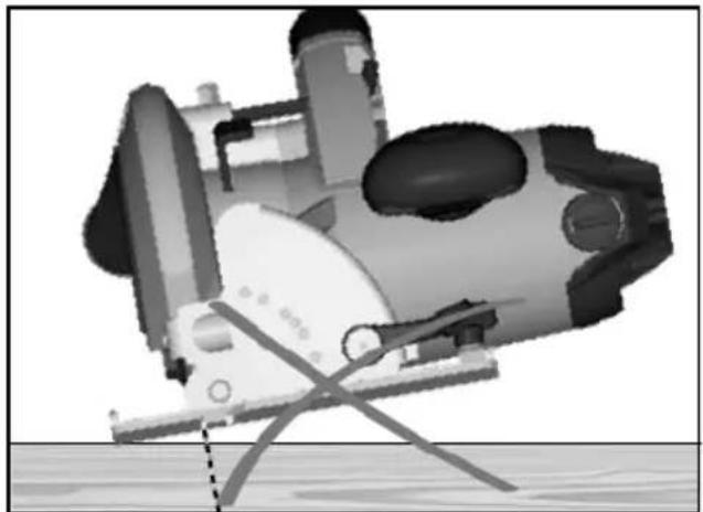
natural_image
Illustration of a submarine underwater with visible hull, hull, and support structure (no text or symbols)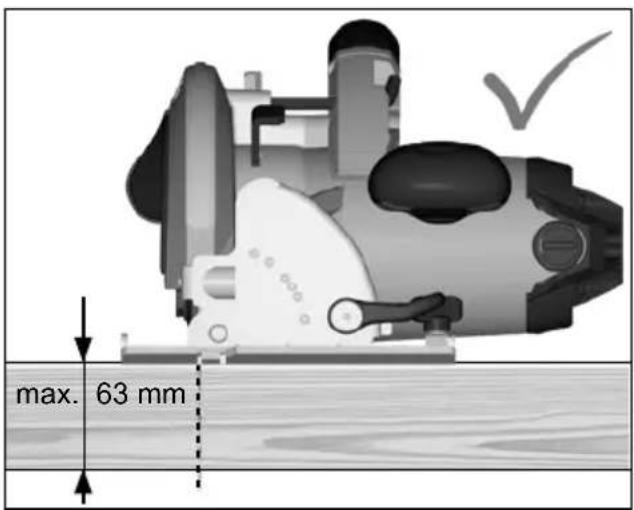

natural_image
Illustration of a submarine underwater with visible hull, hull, and trajectory lines (no text or symbols)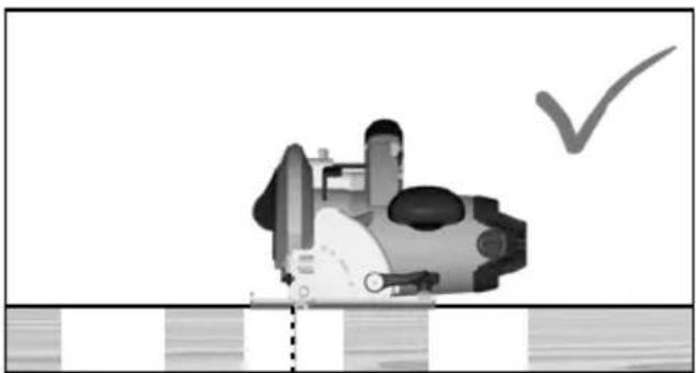
natural_image
Illustration of a submarine with a checkmark indicating a verification or inspection (no text or symbols present)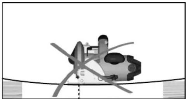
natural_image
Illustration of a submarine with visible propellers and fuselage, resting on a curved surface (no text or symbols)| TECHNICAL DATA CIRCULAR SAW | KS 66-2 |
| Production code 4466 76 06 ... | 4601 60 05 ... ... 000001-999999 |
| Rated input 1600 W | |
| No-load speed 5800 min | -1 |
| Saw blade dia. x hole dia 190 x 30 mm | |
| Saw blade thickness 2,2 mm | |
| Max. Cutting depth at 0° / 45° / 56° 63 / 47 / 36 mm | |
| Weight according EPTA-Procedure 01/2014 4,8 kg | |
| Noise informationMeasured values determined according to EN 62841.Typically, the A-weighted noise levels of the tool are:Sound pressure level (Uncertainty K=3dB(A)) 93,5 dB(A)Sound power level (Uncertainty K=3dB(A)) 104,5 dB(A)Wear ear protectors! | |
| Vibration informationVibration total values (triaxial vector sum) determined according to EN 62841Sawing of woodVibration emission value a_h,W Uncertainty K=1,5 m/s | 4,5 m/ s^2 2 |
WARNING!
The vibration and noise emission level given in this information sheet has been measured in accordance with a standardized test given in EN 62841 and may be used to compare one tool with another. It may be used for a preliminary assessment of exposure.
The declared vibration and noise emission level represents the main applications of the tool. However if the tool is used for different applications, with different accessories or poorly maintained, the vibration and noise emission may differ. This may significantly increase the exposure level over the total working period.
An estimation of the level of exposure to vibration and noise should also take into account the times when the tool is switched off or when it is running but not actually doing the job. This may significantly reduce the exposure level over the total working period.
Identify additional safety measures to protect the operator from the effects of vibration and/or noise such as: maintain the tool and the accessories, keep the hands warm, organization of work patterns.

WARNING Read all safety warnings, instructions,
illustrations and specifications provided with this power tool.
Failure to follow all instructions listed below may result in electric shock, fire and/or serious injury.
Save all warnings and instructions for future reference.

CIRCULAR SAW SAFETY WARNINGS
Cutting procedures

DANGER: Keep hands away from cutting area and e. Keep your second hand on auxiliary handle, or
motor housing. If both hands are holding the saw, they cannot be cut by the blade.
b) Do not reach underneath the workpiece. The guard cannot protect you from the blade below the workpiece.
c) Adjust the cutting depth to the thickness of the workpiece. Less than a full tooth of the blade teeth should be visible below the workpiece.
d) Never hold the workpiece in your hands or across your leg while cutting. Secure the workpiece to a stable platform. It is important to support the work properly to minimise body exposure, blade binding, or loss of control.
e) Hold the power tool by insulated gripping surfaces, when performing an operation where the cutting accessory may contact hidden wiring or its own cord. Contact with a "live" wire will also make exposed metal parts of the power tool "live" and could give the operator an electric shock.
f) When ripping, always use a rip fence or straight edge guide. This improves the accuracy of cut and reduces the chance of blade binding.
g) Always use blades with correct size and shape (diamond versus round) of arbour holes. Blades that do not match the mounting hardware of the saw will run off-centre, causing loss of control.
h) Never use damaged or incorrect blade washers or bolt.
The blade washers and bolt were specially designed for your saw, for optimum performance and safety of operation.
Kickback causes and related warnings
- kickback is a sudden reaction to a pinched, jammed or misaligned saw blade, causing an uncontrolled saw to lift up and out of the workpiece toward the operator;
- when the blade is pinched or jammed tightly by the kerf closing down, the blade stalls and the motor reaction drives the unit rapidly back toward the operator;
- if the blade becomes twisted or misaligned in the cut, the teeth at the back edge of the blade can dig into the top surface of the wood causing the blade to climb out of the kerf and jump back toward the operator.
Kickback is the result of saw misuse and/or incorrect operating procedures or conditions and can be avoided by taking proper precautions as given below.
a) Maintain a firm grip with both hands on the saw and position your arms to resist kickback forces. Position your body to either side of the blade, but not in line with the blade. Kickback could cause the saw to jump backwards, but kickback forces can be controlled by the operator, if proper precautions are taken.
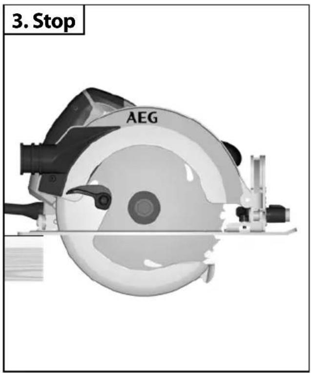
b) When blade is binding, or when interrupting a cut for any reason, release the trigger and hold the saw motionless in the material until the blade comes to a complete stop. Never attempt to remove the saw from the work or pull the saw backward while the blade is in motion or kickback may occur. Investigate and take corrective actions to eliminate the cause of blade binding.
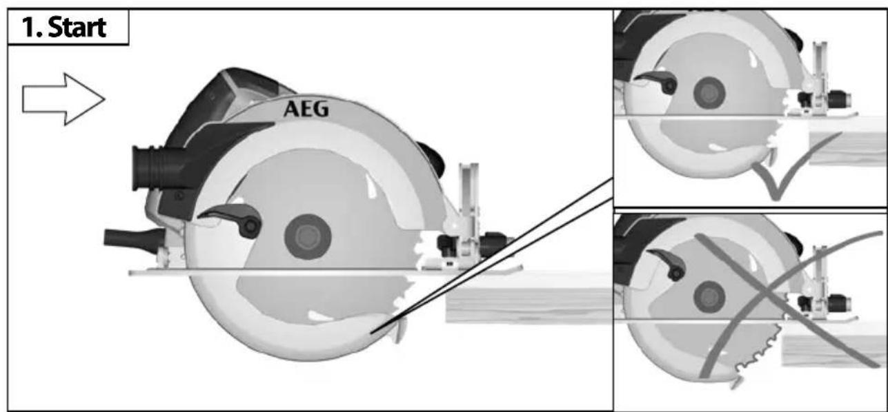
c) When restarting a saw in the workpiece, centre the saw blade in the kerf so that the saw teeth are not engaged into the material. If a saw blade binds, it may walk up or kickback from the workpiece as the saw is restarted.
d) Support large panels to minimise the risk of blade pinching and kickback. Large panels tend to sag under their own weight. Supports must be placed under the panel on both sides, near the line of cut and near the edge of the panel.
e) Do not use dull or damaged blades. Unsharpened or improperly set blades produce narrow kerf causing excessive friction, blade binding and kickback.
f) Blade depth and bevel adjusting locking levers must be tight and secure before making the cut. If blade adjustment shifts while cutting, it may cause binding and kickback.
g) Use extra caution when sawing into existing walls or other blind areas. The protruding blade may cut objects that can cause kickback.
Lower guard function
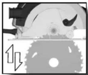
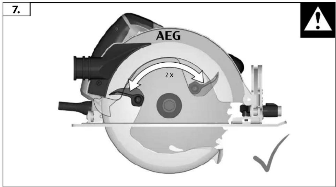
a) Check the lower guard for proper closing before each use. Do not operate the saw if the lower guard does not move freely and close instantly. Never clamp or tie the lower guard into the open position. If the saw is accidentally dropped, the lower guard may be bent. Raise the lower guard with the retracting handle and make sure it moves freely and does not touch the blade or any other part, in all angles and depths of cut.
b) Check the operation of the lower guard spring. If the guard and the spring are not operating properly, they must be serviced before use. Lower guard may operate sluggishly due to damaged parts, gummy deposits, or a build-up of debris.
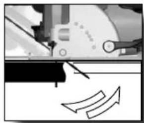
c) The lower guard may be retracted manually only for special cuts such as "plunge cuts" and "compound cuts". Raise the lower guard by the retracting handle and as soon as the blade enters the material, the lower guard must be released. For all other sawing, the lower guard should operate automatically.
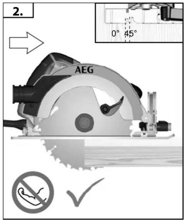
d) Always observe that the lower guard is covering the blade before placing the saw down on bench or floor. An unprotected, coasting blade will cause the saw to walk backwards, cutting whatever is in its path. Be aware of the time it takes for the blade to stop after switch is released.
ADDITIONAL SAFETY AND WORKING INSTRUCTIONS
Wear ear protectors. Exposure to noise can cause hearing loss.
Use protective equipment. Always wear safety glasses when working with the machine. The use of protective clothing is recommended, such as dust mask, protective gloves, sturdy non-slip footwear, helmet and ear defenders.
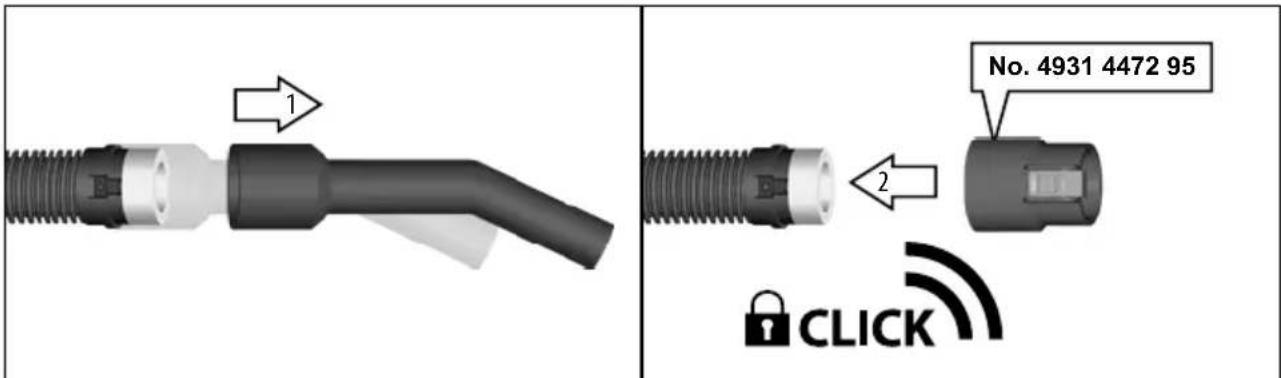
The dust produced when using this tool may be harmful to health. Do not inhale the dust. Use a dust absorption system and wear a suitable dust protection mask. Remove deposited dust thoroughly, e.g. with a vacuum cleaner.
Do not use saw blades not corresponding to the key data given in these instructions for use.
It is necessary to select a saw blade which is suitable for the material being cut.
Use only woodworking blades specified in this manual, which comply with EN 847-1.
The rated speed of the accessory must be at least equal to the maximum speed marked on the power tool.
Do not use abrasion discs in this machine!
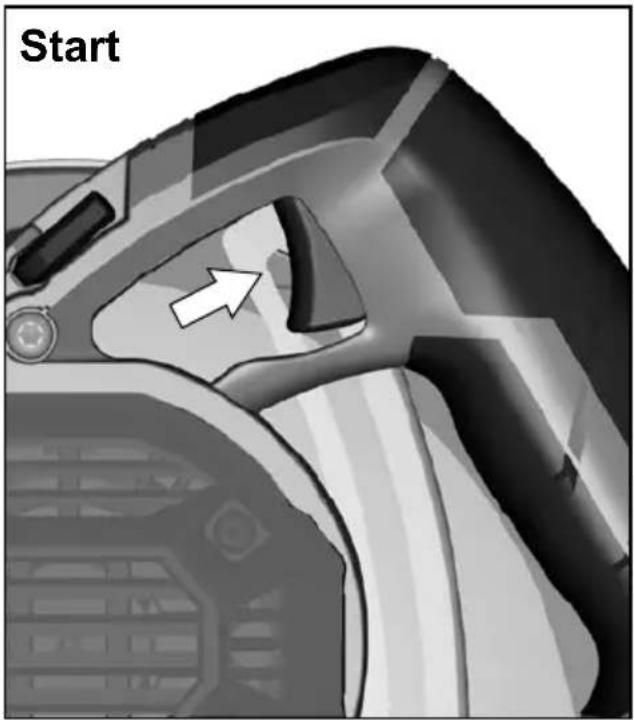
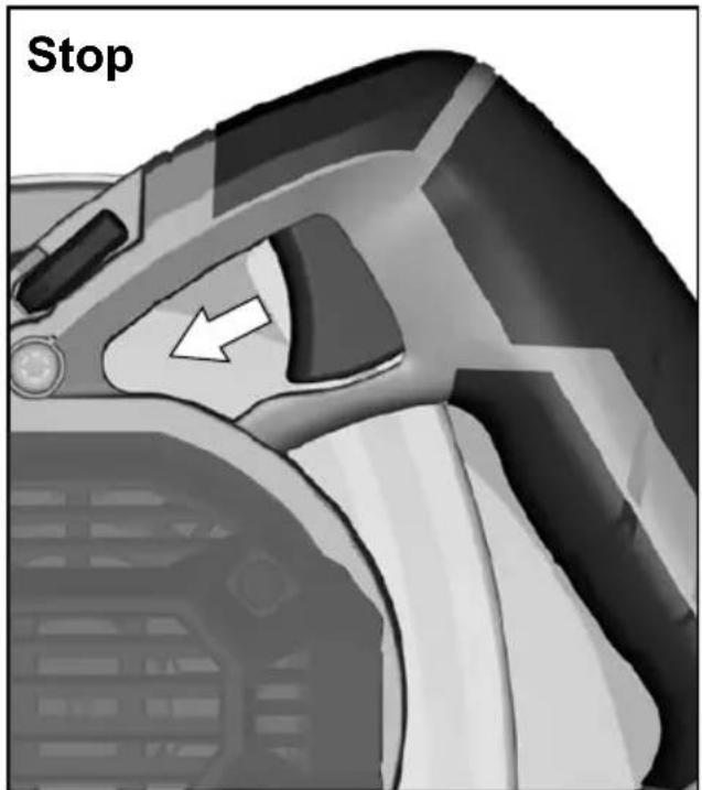
Do not fix the on/off switch in the "on" position when using the saw hand-held.
WORKING INSTRUCTIONS
Adapt the feed speed to avoid overheating the blade tips.
MAINS CONNECTION
Connect only to single-phase AC system voltage as indicated on the rating plate. It is also possible to connect to sockets without an earthing contact as the design conforms to safety class II.
Appliances used at many different locations including wet room and open air must be connected via a residual current device (FI, RCD, PRCD) of 30mA or less.
Only plug-in when machine is switched off.
Do not let any metal parts enter the airing slots - danger of short circuit!
Keep mains lead clear from working range of the machine. Always lead the cable away behind you.
Before use check machine, cable, safety harness and plug for any damages or material fatigue. Repairs should only be carried out by authorised Service Agents.
A power spike causes voltage fluctuations and may affect other electrical products in the same power line. Connect the product to a power supply with an impedance equal to 0,368 Ω to minimize voltage fluctuations.
SPECIFIED CONDITIONS OF USE
This electronic circular saw can cut lengthways and mitre accurately in wood.
MAINTENANCE
Always disconnect the plug from the socket before carrying out any work on the machine.
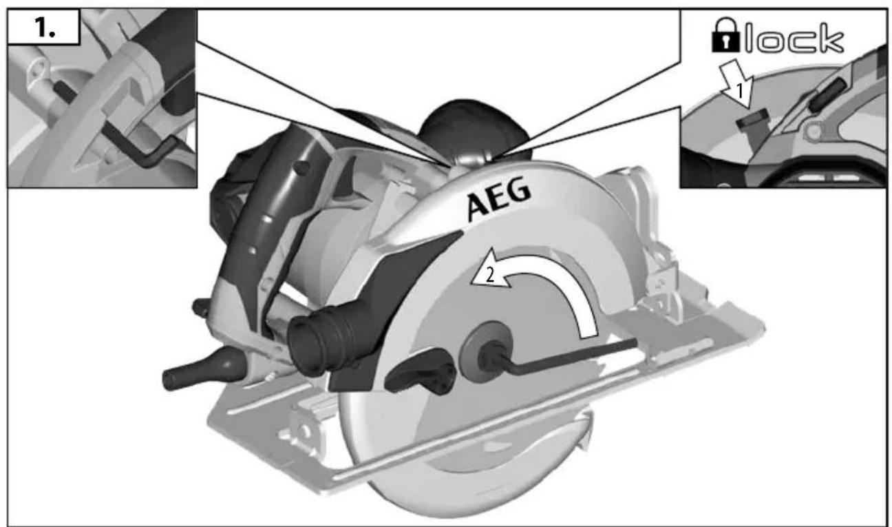
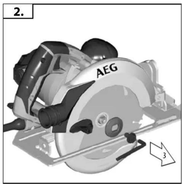
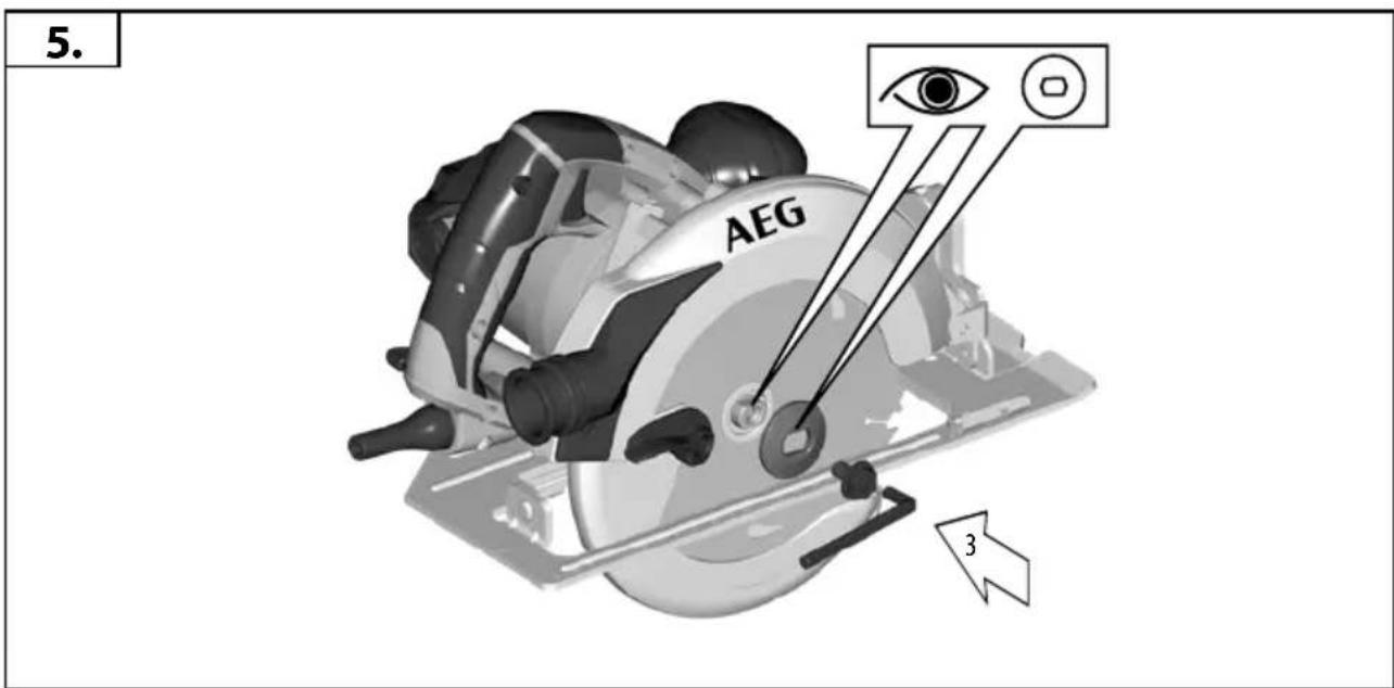
Be sure to disconnect the tool from the power supply before attaching or removing the saw blade.
Clean tool and guarding system with dry cloth.
Certain cleaning agents and solvents are harmful to plastics and other insulated parts.
The ventilation slots of the machine must be kept clear at all times.
Remove dust regularly. Remove the sawdust which has accumulated inside the saw in order to avoid the risk of fire.
Keep the apparatus handle clean, dry and free of spilt oil or grease.
Check the function of guards.
Regular maintenance and cleaning provide for a long service life and safe handling.
If the replacement of the supply cord is necessary, this has to be done by the manufacturer or his agent in order to avoid a safety hazard.
Use only AEG accessories and spare parts. Should components need to be replaced which have not been described, please contact one of our AEG service agents (see our list of guarantee/service addresses).
If needed, an exploded view of the tool can be ordered. Please state the Article No. as well as the machine type printed on the label and order the drawing at your local service agents or directly at: Techtronic Industries GmbH, Max-Eyth-Straße 10, 71364 Winnenden, Germany.
English
EC-DECLARATION OF CONFORMITY
We declare under our sole responsibility that the product described under "Technical Data" fulfills all the relevant provisions of the directives
2006/42/EC
2014/30/EU
2011/65/EU (RoHS)
and the following harmonized standards have been used.
EN 62841-1:2015
EN 62841-2-5:2014
EN 55014-1:2017+A11:2020
EN 55014-2: 2015
EN 61000-3-2:2014
EN 61000-3-11:2000
EN IEC 63000:2018
Winnenden, 2020-11-16
Alexander Krug / Managing Director
Authorized to compile the technical file
Techtronic Industries GmbH
Max-Eyth-Straße 10, 71364 Winnenden, Germany
GB-DECLARATION OF CONFORMITY
We declare as the manufacturer under our sole responsibility that the product described under "Technical Data" fulfills all the relevant provisions of the following Regulations
S.I. 2012/3032 (as amended), S.I. 2008/1597 (as amended),
S.I. 2016/1091 (as amended) and that the following designated standards have been used:
BS EN 62841-1:2015
BS EN 62841-2-5:2014
BS EN 55014-1:2017+A11:2020
BS EN 55014-2:2015
BS EN 61000-3-2:2014
BS EN 61000-3-11:2001
BS EN IEC 63000:2018
Winnenden, 2020-11-16
Alexander Krug / Managing Director
Authorized to compile the technical file
Techtronic Industries GmbH
Max-Eyth-Straße 10, 71364 Winnenden, Germany
SYMBOLS

CAUTION! WARNING! DANGER!

Please read the instructions carefully before starting the machine.

Always wear goggles when using the machine.

Wear ear protectors!

Wear a suitable dust protection mask.

Wear gloves!

Always disconnect the plug from the socket before carrying out any work on the machine.

Do not use force.

Accessory - Not included in standard equipment, available as an accessory.

Do not dispose of electric tools together with household waste material. Electric tools and electronic equipment that have reached the end of their life must be collected separately and returned to an environmentally compatible recycling facility. Check with your local authority or retailer for recycling advice and collection point.

Class II tool. Tool in which protection against electric shock does not rely on basic insulation only, but in which additional safety precautions, such as double insulation or reinforced insulation, are provided. There being no provision for protective earthing or reliance upon installation conditions.
n_0
No-load speed
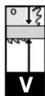
V
Voltage
\~
AC Current

European Conformity Mark

British Conformity Mark

Ukraine Conformity Mark

EurAsian Conformity Mark
Winnenden, 2020-11-16
Alexander Krug / Managing Director
Max-Eyth-Straße 10, 71364 Winnenden, Germany
SYMBOLE

DÉCLARATION CE DE CONFORMITÉ
Winnenden, 2020-11-16
Alexander Krug / Managing Director
Max-Eyth-Straße 10, 71364 Winnenden, Germany
SYMBOLES

ATTENTION! AVERTISSEMENT! DANGER!

Winnenden, 2020-11-16
Alexander Krug / Managing Director
Max-Eyth-Straße 10, 71364 Winnenden, Germany
Italiano
SIMBOLI

ATTENZIONE! AVVERTENZA! PERICOLO!

Winnenden, 2020-11-16
Alexander Krug / Managing Director
Max-Eyth-Straße 10, 71364 Winnenden, Germany
SÍMBOLOS

Winnenden, 2020-11-16
Alexander Krug / Managing Director
Max-Eyth-Straße 10, 71364 Winnenden, Germany
SYMBOLE

ATENÇÃO! PERIGO!

Winnenden, 2020-11-16
Alexander Krug / Managing Director
Max-Eyth-Straße 10, 71364 Winnenden, Germany
SYMBOLLEN

OPGELET! WAARSCHUWING! GEVAAR!

Winnenden, 2020-11-16
Alexander Krug / Managing Director
Max-Eyth-Straße 10, 71364 Winnenden, Germany
SYMBOLER

VIGTIGT! ADVARSEL! FARE!

Winnenden, 2020-11-16
Alexander Krug / Managing Director
Max-Eyth-Straße 10, 71364 Winnenden, Germany
SYMBOLER

OBS! ADVARSEL! FARE!

Winnenden, 2020-11-16
Alexander Krug / Managing Director
Max-Eyth-Straße 10, 71364 Winnenden, Germany
SYMBOLER

OBSERVERA! WARNING! FARA!

Läs instruktionen noga innan du startar maskinen.

Winnenden, 2020-11-16
Alexander Krug / Managing Director
Max-Eyth-Straße 10, 71364 Winnenden, Germany
SYMBOLIT

HUOMIO! VAROITUS! VAARA!

Winnenden, 2020-11-16
Alexander Krug / Managing Director
Max-Eyth-Straße 10, 71364 Winnenden, Germany
ΣΥΜΒΟΛΑ

Winnenden, 2020-11-16
Alexander Krug / Managing Director
Max-Eyth-Straße 10, 71364 Winnenden, Germany
SEMBOLLER

DİKKAT! UYARI! TEHLİKE!

DALŠÍ BEZPEČNOSTNÍ A PRACOVNÍ POKYNY
Winnenden, 2020-11-16
Alexander Krug / Managing Director
Max-Eyth-Straße 10, 71364 Winnenden, Germany
SYMBOLY

POZOR! VAROVÁN! NEBEZPEČÍ!

ĎALŠIE BEZPEČNOSTNÉ A PRACOVNÉ POKYNY
CE - VYHLÁSENIE KONFORMITY
Winnenden, 2020-11-16
Max-Eyth-Straße 10, 71364 Winnenden, Germany
SYMBOLY

POZOR! NEBEZPEČENSTVO!

Winnenden, 2020-11-16
Alexander Krug / Managing Director
Max-Eyth-Straße 10, 71364 Winnenden, Germany
SYMBOLE

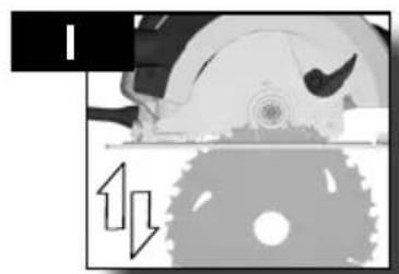
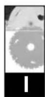
Function of the bottom guard
Winnenden, 2020-11-16
Alexander Krug / Managing Director
Max-Eyth-Straße 10, 71364 Winnenden, Germany
SZIMBÓLUMOK

FIGYELEM! FIGYELMEZTETÉS! VESZÉLY!

UPORABA V SKLADU Z NAMEMBNOSTJO
Winnenden, 2020-11-16
Alexander Krug / Managing Director
Max-Eyth-Straße 10, 71364 Winnenden, Germany
SIMBOLI

POZOR! OPOZORILO! NEVARNO!

Prosimo, da pred uporabo pozorno preberete to navodilo za uporabo.

OSTALE SIGURNOSNE I RADNE UPUTE
Nosite zaštitu za sluh. Djelovanje buke može uzrokovati gubitak sluha.
Winnenden, 2020-11-16
Alexander Krug / Managing Director
Ovlašten za formiranje tehničke dokumentacije.
Techtronic Industries GmbH
Max-Eyth-Straße 10, 71364 Winnenden, Germany
SIMBOLI

PAŽNJA! UPOZORENIE! OPASNOST!

Molimo da pažljivo pročitate uputu o upotrebi prije puštanja u rad.

ATBILSTIBA CE NORMAM
Winnenden, 2020-11-16
Alexander Krug / Managing Director
Max-Eyth-Straße 10, 71364 Winnenden, Germany
SIMBOLI

UZMANİBU! BİSTAMI!

Winnenden, 2020-11-16
Alexander Krug / Managing Director lgaliotas parengti techninius dokumentus.
Techtronic Industries GmbH
Max-Eyth-Straße 10, 71364 Winnenden, Germany
SIMBOLIAI

DÊMESIO! JSPÊJIMAS! PAVOJUS!

EDASISED OHUTUS- JA TÖÖJUHISED
Winnenden, 2020-11-16
Alexander Krug / Managing Director
Max-Eyth-Straße 10, 71364 Winnenden, Germany
SÜMBOLID

ETTEVAATUST! TÄHELEPANU! OHUD!

Winnenden, 2020-11-16
Alexander Krug / Managing Director
Max-Eyth-Straße 10, 71364 Winnenden, Germany
СИМВОЛЫ

Winnenden, 2020-11-16
Alexander Krug / Managing Director
Max-Eyth-Straße 10, 71364 Winnenden, Germany
СИМВОЛИ

Winnenden, 2020-11-16
Alexander Krug / Managing Director
Max-Eyth-Straße 10, 71364 Winnenden, Germany
SIMBOLURI

PERICOL! AVERTIZARE! ATENTIE!

Winnenden, 2020-11-16
Alexander Krug / Managing Director
Max-Eyth-Straße 10, 71364 Winnenden, Germany
СИМБОЛИ

ВНИМАНИЕ! ПРЕДУПРЕДУВАЊЕ! ОПАСНОСТ!

Winnenden, 2020-11-16
Alexander Krug / Managing Director
Max-Eyth-Straße 10, 71364 Winnenden, Germany
СИМВОЛИ

ارتدال environmentally!

Winnenden, 2020-11-16
Alexander Krug / Managing Director
Techtronic Industries (UK) Ltd
Fieldhouse Lane
Marlow Bucks SL7 1HZ
UK
- Insulated gripping surface
- WARNING!
- WARNING Read all safety warnings, instructions,
- CIRCULAR SAW SAFETY WARNINGS
- Cutting procedures
- DANGER: Keep hands away from cutting area and e. Keep your second hand on auxiliary handle, or
- Kickback causes and related warnings
- Lower guard function
- ADDITIONAL SAFETY AND WORKING INSTRUCTIONS
- WORKING INSTRUCTIONS
- MAINS CONNECTION
- SPECIFIED CONDITIONS OF USE
- MAINTENANCE
- English
- EC-DECLARATION OF CONFORMITY
- GB-DECLARATION OF CONFORMITY
- SYMBOLS
- SYMBOLE
- DÉCLARATION CE DE CONFORMITÉ
- SYMBOLES
- Italiano
- SIMBOLI
- SÍMBOLOS
- SYMBOLLEN
- SYMBOLER
- SYMBOLIT
- ΣΥΜΒΟΛΑ
- SEMBOLLER
- DALŠÍ BEZPEČNOSTNÍ A PRACOVNÍ POKYNY
- SYMBOLY
- ĎALŠIE BEZPEČNOSTNÉ A PRACOVNÉ POKYNY
- CE - VYHLÁSENIE KONFORMITY
- Function of the bottom guard
- SZIMBÓLUMOK
- UPORABA V SKLADU Z NAMEMBNOSTJO
- OSTALE SIGURNOSNE I RADNE UPUTE
- ATBILSTIBA CE NORMAM
- SIMBOLIAI
- EDASISED OHUTUS- JA TÖÖJUHISED
- SÜMBOLID
- СИМВОЛЫ
- СИМВОЛИ
- SIMBOLURI
- СИМБОЛИ
Brand : AEG
Model : KS 662
Category : Jigsaw