
FMHT775981 - Laser level STANLEY - Free user manual and instructions
Find the device manual for free FMHT775981 STANLEY in PDF.
| Product Type | Cross-line laser level |
| Brand | STANLEY |
| Model | FMHT775981 |
| Light Source | Laser diodes |
| Laser Wavelength | 510-530 nm (visible) |
| Laser Power | ≤1.0 mW |
| Laser Class | 2 |
| Operating Range | 30 m (100 ft) |
| Accuracy (Bottom Point) | ±6 mm per 10 m |
| Accuracy (Lines and Other Points) | ±3 mm per 10 m (typical) |
| Operating Temperature | -10 °C to 50 °C |
| Storage Temperature | -20 °C to 60 °C |
| Protection Rating | IP54 (water and dust resistant) |
| Power Supply | Rechargeable Li-ion battery (included) |
| Main Functions | Horizontal and vertical lines, 5 points, pulse mode, self-leveling (up to ±4°) |
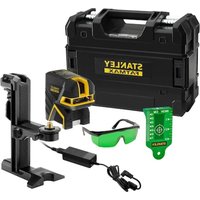
| Box Contents | Laser level, charger, support block |
| Maintenance and Cleaning | Clean with a damp cloth and dry; do not use solvents |
| Safety | Class 2 laser product; do not stare directly into the beam |
| Replacement Parts and Repairability | Repairs exclusively by an authorized Stanley service center; parts available via customer service |
Frequently Asked Questions - FMHT775981 STANLEY
User questions about FMHT775981 STANLEY
0 question about this device. Answer the ones you know or ask your own.
Ask a new question about this device
Download the instructions for your Laser level in PDF format for free! Find your manual FMHT775981 - STANLEY and take your electronic device back in hand. On this page are published all the documents necessary for the use of your device. FMHT775981 by STANLEY.
USER MANUAL FMHT775981 STANLEY
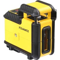
Self-Leveling 5-Dot Cross Line Laser
www.2helpU.com
Please read these instructions before operating the product.

B
C
Figures
D
E
①
H
Figures
①
K
J
(1)
②
③
(4)
Contents
- Laser Information
- User Safety
- Charging the Battery
- Turning the Laser On
Using the Mounting Block - Checking Laser Accuracy
Using the Laser - Maintenance
- Troubleshooting
Service and Repairs - Specifications
Laser Information
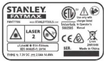
The FMHT77598 laser is a Class 2 laser product. The laser is a self-leveling laser tool that can be used for horizontal (level) and vertical (plumb) alignment projects.
User Safety
Safety Guidelines
The definitions below describe the level of severity for each signal word. Please read the manual and pay attention to these symbols.

DANGER: Indicates an imminently hazardous situation which, if not avoided, will result in death or serious injury.

WARNING: Indicates a potentially hazardous situation which, if not avoided, could result in death or serious injury.

CAUTION: Indicates a potentially hazardous situation which, if not avoided, may result in minor or moderate injury.
NOTICE: Indicates a practice not related to personal injury which, if not avoided, may result in property damage.
If you have any questions or comments about this or any Stanley tool, go to http://www.2helpU.com.
EC-Declaration of Conformity

Stanley herewith declares that the product FMHT77598 is in compliance with the essential requirements and all other provisions of Directive 1999/5/EC.
The full text of the EU Declaration of Conformity can be requested at Stanley Tools, Egide Walschaertsstraat 14-16, 2800 Mechelen, Belgium or is available at the following internet address: www.2helpu.com.

WARNING:
Read and understand all instructions. Failure to follow the warnings and instructions in this manual may result in serious personal injury.
SAVE THESE INSTRUCTIONS

WARNING:
Laser Radiation Exposure. Do not disassemble or modify the laser level. There are no user serviceable parts inside. Serious eye injury could result.

WARNING:
Hazardous Radiation. Use of controls or adjustments, or performance of procedures, other than those specified herein may result in hazardous radiation exposure.
The label on your laser may include the following symbols.
| Symbol Meaning | |
| V Volts | |
| mW Milliwatts | |
| 4 | Laser Warning |
| nm Wavelength in | nanometers |
| 2 Class 2 Laser |
Warning Labels
For your convenience and safety, the following labels are on your laser.


WARNING: To reduce the risk of injury, user must read instruction manual.

WARNING: LASER RADIATION. DO NOT STARE INTO BEAM. Class 2 Laser Product.
GB
- If the equipment is used in a manner not specified by the manufacturer, the protection provided by the equipment may be impaired.
- Do not operate the laser in explosive atmospheres, such as in the presence of flammable liquids, gases, or dust. This tool may create sparks which may ignite the dust or fumes.
- Store an idle laser out of reach of children and other untrained persons. Lasers are dangerous in the hands of untrained users.
- Tool service MUST be performed by qualified repair personnel. Service or maintenance performed by unqualified personnel may result in injury. To locate your nearest Stanley service center go to http://www.2helpU.com.
- Do not use optical tools such as a telescope or transit to view the laser beam. Serious eye injury could result.
- Do not place the laser in a position which may cause anyone to intentionally or unintentionally stare into the laser beam. Serious eye injury could result.
- Do not position the laser near a reflective surface which may reflect the laser beam toward anyone's eyes. Serious eye injury could result.
- Turn the laser off when it is not in use. Leaving the laser on increases the risk of staring into the laser beam.
- Do not modify the laser in any way. Modifying the tool may result in hazardous laser radiation exposure.
- Do not operate the laser around children or allow children to operate the laser. Serious eye injury may result.
- Do not remove or deface warning labels. If labels are removed, the user or others may inadvertently expose themselves to radiation.
- Position the laser securely on a level surface. If the laser falls, damage to the laser or serious injury could result.
Personal Safety
- Stay alert, watch what you are doing, and use common sense when operating the laser. Do not use the laser when you are tired or under the influence of drugs, alcohol, or medication. A moment of inattention while operating the laser may result in serious personal injury.
- Use personal protective equipment. Always wear eye protection. Depending on the work conditions, wearing protective equipment such as a dust mask, non-skid safety shoes, hard hat, and hearing protection will reduce personal injury.
Tool Use and Care
- Do not use the laser if the Power/Transport Lock switch does not turn the laser on or off. Any tool that cannot be controlled with the switch is dangerous and must be repaired.
- Follow instructions in the Maintenance section of this manual. Use of unauthorized parts or failure to follow Maintenance instructions may create a risk of electric shock or injury.
Battery Safety
The FMHT77598 laser is powered by a Li-ion battery.

WARNING:
To reduce the risk of injury, the user must read the product User Manual, Laser Safety Manual, and the Battery Safety Manual.
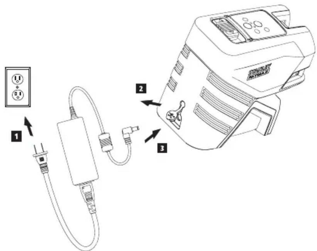
Charging the Battery
Use the charging unit that is packaged with the FMHT77598 laser to charge the laser's Li-ion battery.
- Insert the electrical plug at one end of the charging unit into an electrical outlet (Figure C 1).
- On the back of the laser, pull the port cover off and to the side (Figure ②).
- Insert the small end of the charging unit into the laser's charging port (Figure C 3).
- Allow the battery time to fully-charge. The Power LED will remain on while the battery is charging.
-
After the Power LED turns off, disconnect the charging unit from the electrical outlet and the laser's charging port.
-
Push the port cover back over the laser's charging port.
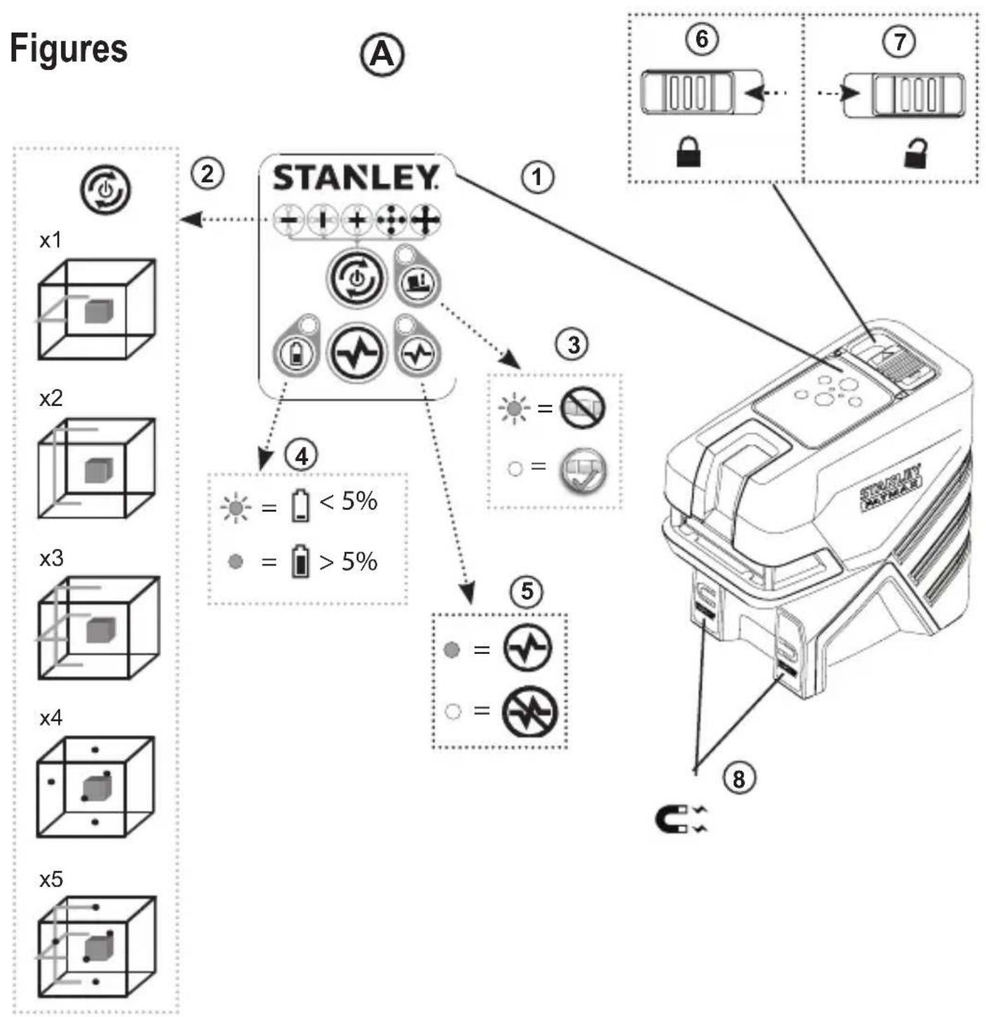
Whenever the laser is not in use, slide the Power/Transport Lock switch to the LEFT to the Locked/OFF position (Figure A) to save battery power.
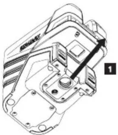
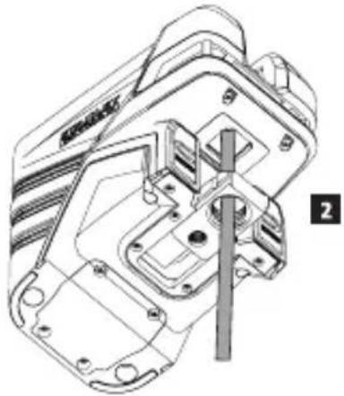
Using the Mounting Block
On the bottom of the laser is a moveable block (Figure D).
- To use the magnets on the front of the laser (Figure A 8) to mount the laser against the side of a steel beam, do not extend the moveable block (Figure D 1). This will allow the down dot to be aligned with the edge of the steel beam.
- To mount the laser over a point on the floor (using a multifunction bracket or a tripod), pull out the moveable block until it clicks in place (Figure D ②). This will allow the laser down dot to display through the 5/8-11 mounting hole and the laser to be rotated over the 5/8-11 mounting hole without moving the vertical position of the laser.
Turning the Laser On
- Place the laser on a smooth, flat, level surface.
- Slide the Power/Transport Lock switch to the right to the Unlocked/ON position (Figure A 7).
- As shown in Figure A 2, press once to display a horizontal laser line, a second time to display a vertical laser line, a third time to display a horizontal line and a vertical line, a fourth time to display 5 dots, and a fifth time to display the horizontal and vertical lines with the 5 dots.
- Check the laser beams. The laser is designed to self-level. If the laser is tilted so much that it cannot self-level (>4^) , the laser beams will continually flash twice and will flash constantly on the keypad (Figure A 3).
- If the laser beams flash, the laser is not level (or plumb) and should NOT BE USED for determining or marking level or plumb. Try repositioning the laser on a level surface.
-
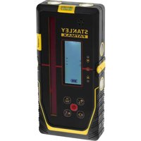
Press on the keypad to test the Pulse mode. will illuminate on the keypad (Figure A 5) and the laser beams will appear lighter, since they are flashing at a very rapid rate. You will only use Pulse mode with a detector to project the laser beams long range.
-
If ANY of the following statements are TRUE, continue with the instructions for Checking Laser Accuracy BEFORE USING THE LASER for a project.
-
This is the first time you are using the laser (in case the laser was exposed to extreme temperatures).
The laser has not been checked for accuracy in a while. - The laser may have been dropped.
Checking Laser Accuracy
The laser tools are sealed and calibrated at the factory. It is recommended that you perform an accuracy check prior to using the laser for the first time (in case the laser was exposed to extreme temperatures) and then regularly to ensure the accuracy of your work. When performing any of the accuracy checks listed in this manual, follow these guidelines:
- Use the largest area/distance possible, closest to the operating distance. The greater the area/distance, the easier to measure the accuracy of the laser.
- Place the laser on a smooth, flat, stable surface that is level in both directions.
- Mark the center of the laser beam.
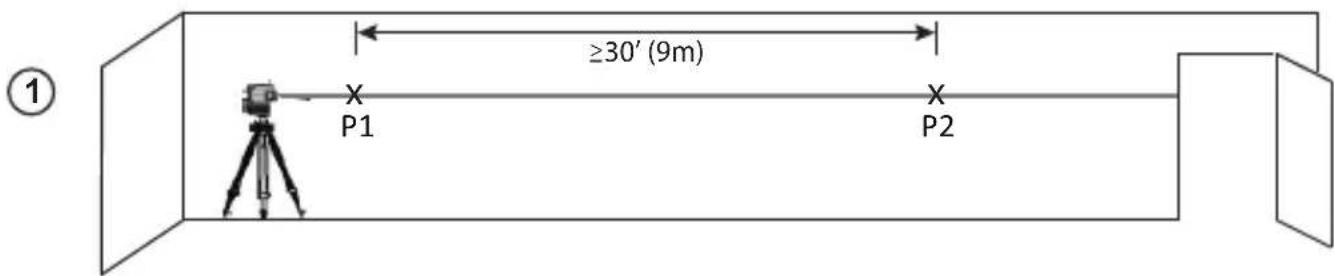
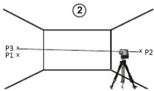
Horizontal Line Accuracy - Level
Checking the level of the laser's horizontal line requires a flat vertical surface at least 30^ (9 m) wide.
- Place a tripod at one end of the wall (Figure E ①).
- Place the laser on a tripod and screw the threaded knob on the tripod into the female thread on the laser.
- Slide the laser's Power/Transport Lock switch to the right to turn the laser ON (Figure A 7).
- Press once to display a horizontal line.
- Mark two points (P1 and P2) at least 30^ (9 m) apart along the length of the laser's horizontal line on the wall.
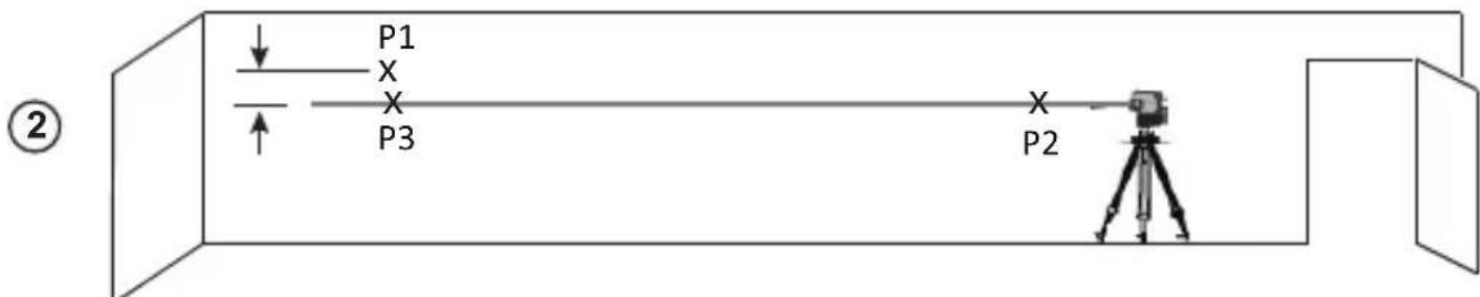
- Relocate the laser at the other end of the wall and align the laser's horizontal line with point P2 (Figure E 2).
- Mark point P3 on the laser line near point P1.
- Measure the vertical distance between points P1 and P3.
GB
- If your measurement is greater than the Allowable Distance Between P1 & P3 for the corresponding Distance Between P1 & P2 in the following table, the laser must be serviced at an authorized service center.
| Distance Between P1 & P2 | Allowable Distance Between P1 and P3 |
| 9 m (30') 6 mm (1/4") | |
| 12 m (40') 8 mm (5/16") | |
| 15 m (50') 10 mm (13/32") | |
Horizontal Line Accuracy - Tilt
Checking the tilt of the laser's horizontal line requires a flat vertical surface at least 30^ (9m) wide.
-
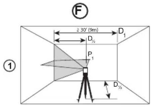
Place a tripod as shown in Figure F ①, which is:
-
At the center of the wall (D 1/2).
In front of the wall at a distance of half the size of the wall (D 1/2). -
Place the laser on a tripod and screw the threaded knob on the tripod into the female thread on the laser.
- Slide the laser's Power/Transport Lock switch to the right to turn the laser ON (Figure A 7).
- Press 3 times to display a horizontal line and a vertical line.
- Aim the laser's vertical line at the first corner or reference point (Figure F 1).
- Measure half the distance across the wall (D1/2).
- Where the horizontal laser line crosses the halfway point (D1 / 2) , mark point P1.
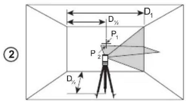
- Rotate the laser to another corner or reference point (Figure F 2).
- Where the horizontal laser line crosses the halfway point (D1 / 2) ,mark point P2).
-
Measure the vertical distance between P1 and P2 (Figure F 3).
-
If your measurement is greater than the Allowable Distance Between P1 & P2 for the corresponding Distance (D1) in the following table, the laser must be serviced at an authorized service center.
| Distance (D1) | Allowable Distance Between P1 and P2 |
| 9 m (30') 3 mm (1/8") | |
| 12 m (40') 4 mm (5/32") | |
| 15 m (50') 5 mm (7/32") | |
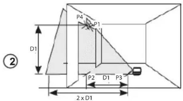
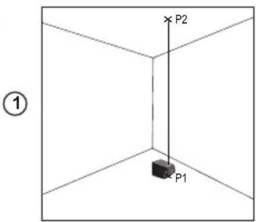
Vertical Line Accuracy - Plumb
Checking the plumb of the laser's vertical line.
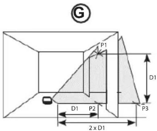
Measure the height of a door jamb (or a reference point on the ceiling) to get height D1 (Figure G 1).
2. Place the laser on the floor across from the door jam, (Figure G 1).
3. Slide the laser's Power/Transport Lock switch to the right to turn the laser ON (Figure A 7).
4. Press twice to display a vertical line.
5. Aim the laser's vertical line toward the door jamb or the reference point on the ceiling.
6. Where the laser's vertical line meets the height of the door jam, mark point P1.
7. From where the laser beam hits the floor, measure the D1 distance and mark it point P2.
8. From P2, measure the D1 distance and mark it point P3.
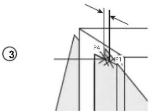
9. Move the laser to the opposite side of point P3 and aim the laser's vertical line toward point P2 (Figure ⑥ ②).
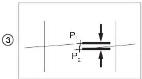
10. Align the laser's vertical line with points P2 and P3 on the floor, and mark point P4 over the door jam.
11. Measure the distance between P1 and P4 (Figure G 3).
- If your measurement is greater than the Allowable Distance Between P1 & P4 for the corresponding Vertical Distance (D1) in the following table, the laser must be serviced at an authorized service center.
| Height of Vertical Distance (D1) | Allowable Distance Between P1 and P4 |
| 2.5m (8') 1.5mm | (1/16") |
| 5m (16') 3.0mm | (1/8") |
| 6m (20') 3.6mm | (9/64") |
| 9m (30') 5.5mm | (9/32") |
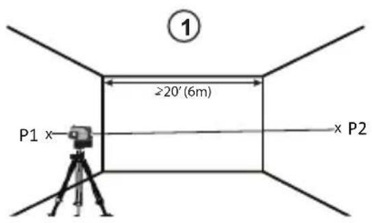
Level Dot Accuracy - Level
Checking the level calibration of the laser unit requires two parallel walls at least 20^ (6 m) apart.
- Place the laser on a tripod and screw the threaded knob on the tripod into the female thread on the laser.
- Turn the laser ON and press 4 times to display dots above, ahead, below, and to the right and left of the laser.
- Place the laser 2^ - 3^ (5-8 cm) from the first wall. To test the front laser dot, make sure the front of the laser is facing the wall (Figure H 1).
- Mark the laser dot position on the first wall as point P1 (Figure H 1).
- Turn the laser 180^ and mark the laser dot position on the second wall as point P2 (Figure H 1).
- Place the laser 2^ - 3^ (5-8 cm) from the second wall. To test the front laser dot, make sure the front of the laser is facing the wall (Figure H 2), and adjust the height of the laser until the laser dot hits point P2.
-
Turn the laser 180^ and aim the laser dot near point P1 on the first wall, and mark point P3 (Figure H 2).
Measure the vertical distance between points P1 and P3 on the first wall. -
If your measurement is greater than the Allowable Distance Between P1 & P3 for the corresponding Distance Between Walls in the following table, the laser must be serviced at an authorized service center.
| Distance Between Walls | Allowable Distance Between P1 & P3 |
| 6.0 m (20') 3.6 mm | (9/64") |
| 9.0 m (30') 5.4 mm | (7/32") |
| 15.0 m (50') 9 mm | (11/32") |
| 23.0 m (75') 13.8 mm | (9/16") |
- Repeat steps 2 through 8 to check the accuracy of the right dot and then the left dot, making sure that the laser dot you are testing is the laser dot facing each wall.
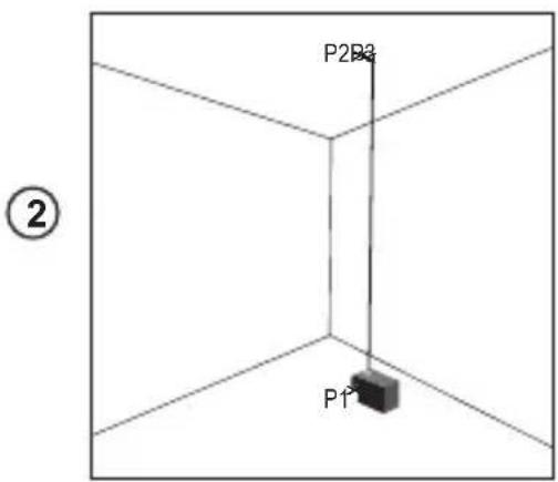
Plumb Dot Accuracy
Checking the plumb calibration of the laser can be most accurately done when there is a substantial amount of vertical height available, ideally 25^ (7.5m) with one person on the floor positioning the laser and another person near a ceiling to mark the dot created by the beam on the ceiling.
- Mark point P1 on the floor (Figure ①①).
- Turn the laser ON and press 4 times to display dots above, ahead, below, and to the right and left of the laser.
- Place the laser so that the down dot is centered over point P1 and mark the center of the up dot on the ceiling as point P2 (Figure ① ①).
- Turn the laser 180^ , making sure that the down dot is still centered on point P1 on the floor (Figure ①②).
- Mark the center of the up dot on the ceiling as point P3 (Figure 1 2).
- Measure the distance between points P2 and P3.
- If your measurement is greater than the Allowable Distance Between P2 & P3 for the corresponding Distance Between Ceiling & Floor in the following table, the laser must be serviced at an authorized service center.
| Distance Between Ceiling & Floor | Allowable Distance Between P2 & P3 |
| 4.5 m (15') 3 mm (1/8") | |
| 6 m (20') 4.2 mm (5/32") | |
| 9 m (30') 6 mm (1/4") | |
| 12 m (40') 8.4 mm (5/16") |
GB
Level Dot Accuracy - Square
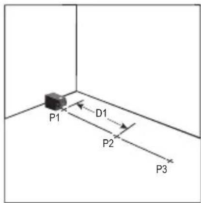
Checking the squareness of the laser beams requires a room at least 35^ (10 m) long. All marks can be made on the floor by placing a target in front of the level or square beam and transferring the location to the floor.
NOTE: To ensure accuracy, the distance (D1) from P1 to P2, P2 to P3, P2 to P4, and P2 to P5 should be equal.
- Mark point P1 on the floor at one end of the room, as shown in Figure ①.
- Turn the laser ON and press ② times to display dots above, ahead, below, and to the right and left of the laser.
- Place the laser so that the down dot is centered over point P1 and make sure the front dot points toward the far end of the room (Figure ①).
- Using a target to transfer the front level dot location on the wall to the floor, mark point P2 on the floor and then point P3 on the floor (Figure ①).
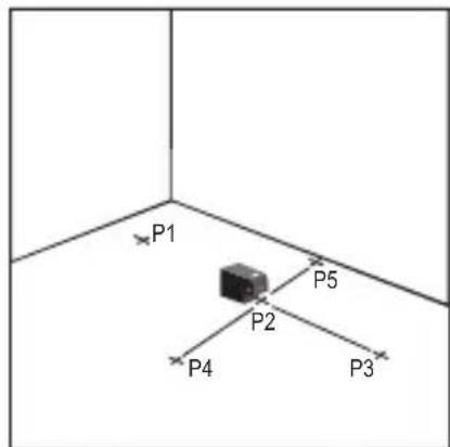
- Move the laser to point P2 and align the front level dot to point P3 again (Figure ②).
- Using a target to transfer the front level dot location on the wall to the floor, mark the location of two square beams as points P4 and P5 on the floor (Figure ②).
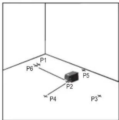
- Turn the laser 90^ so the front level dot aligns to point P4 (Figure ③).
- Mark the location of the first square beam as point P6 on the floor as close as possible to point P1 (Figure 3).
- Measure the distance between points P1 and P6 (Figure 3).
- If your measurement is greater than the Allowable Distance Between P1 & P6 for the corresponding Distance (D1) in the following table, the laser must be serviced at an authorized service center.
| Distance (D1) | Allowable Distance Between P1 & P6 |
| 7.5 m (25') 2.2 mm (3/32") | |
| 9 m (30') 2.7 mm (7/64") | |
| 15 m (50') 4.5 mm (3/16") | |
-
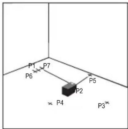
Turn the laser 180^ so the front level dot aligns to point P5 (Figure 4).
-
Mark the location of the second square beam as point P7 on the floor as close as possible to point P1 (Figure ④).
- Measure the distance between points P1 and P7 (Figure ④).
- If your measurement is greater than the Allowable Distance Between P1 & P7 for the corresponding Distance (D1) in the following table, the laser must be serviced at an authorized service center.
| Distance (D1) | Allowable Distance Between P1 & P7 |
| 7.5 m (25') 2.2 mm (3/32") | |
| 9 m (30') 2.7 mm (7/64") | |
| 15 m (50') 4.5 mm (3/16") | |
Using the Laser
Operating Tips
- Always mark the center of the beam created by the laser.
- Extreme temperature changes may cause movement of internal parts that can affect accuracy. Check your accuracy often while working.
- If the laser is ever dropped, check to make sure it is still calibrated.
- As long as the laser is properly calibrated, the laser is self-leveling. Each laser is calibrated at the factory to find level as long as it is positioned on a flat surface within average ± 4^ of level. No manual adjustments are required.
- Use the laser on a smooth, flat, level, surface.
Turning the Laser Off
Slide the Power/Transport Lock switch to the OFF/Locked position (Figure A 6) when the laser is not in use. If the switch is not placed in the Locked position, the laser will not turn off.
Using the Laser with Accessories

WARNING:
Since accessories other than those offered by Stanley have not been tested with this laser, use of such accessories with this laser could be hazardous.
Only use Stanley accessories that are recommended for use with this model. Accessories that may be suitable for one laser may create a risk of injury when used with another laser.
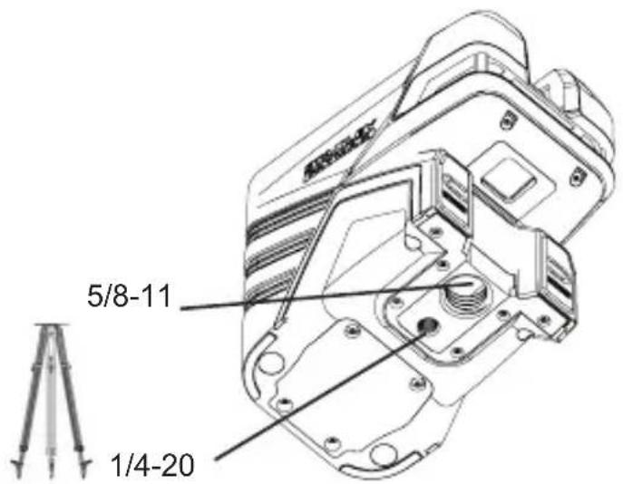
The bottom of the laser is equipped with 1/4-20 and 5/8-11 female threads (Figure B) to accommodate current or future Stanley accessories. Only use Stanley accessories specified for use with this laser. Follow the directions included with the accessory.
Recommended accessories for use with this laser are available at extra cost from your local dealer or authorized service center. If you need assistance locating any accessory, please contact your nearest Stanley service center or visit our website: http://www.2helpU.com.
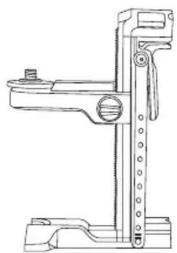
Using the Laser with the Multibracket
Most line/dot lasers which have a 5/8-11 mounting thread can be used with the Multibracket FMHT77435 (Figure K). The multibracket can then be used free-standing or mounted in several ways:
- Use its rubber strap around a pole, 2^ × 4^ , or other vertical object.
- Use its rear magnets against a metal beam.
- Hook its rear screw hole over a nail or screw on a wall.
- Use its ceiling clamp to hold onto the track for a hanging/ suspended ceiling.
- Use the bottom 5/8-11 or 1/4-20 thread to attach to a tripod.
Maintenance
- When the laser is not in use, clean the exterior parts with a damp cloth, wipe the laser with a soft dry cloth to make sure it is dry, and then store the laser in the kit box provided.
- Although the laser exterior is solvent resistant, NEVER use solvents to clean the laser.
- Do not store the laser at temperatures below -20^ (-5°F) or above 60^ (140°F).
- To maintain the accuracy of your work, check the laser often to make sure it is properly calibrated.
- Calibration checks and other maintenance repairs may be performed by Stanley service centers.
Troubleshooting
The Laser Does Not Turn On
- Make sure the laser's Li-ion battery is fully-charged.
- Be sure to keep the laser dry.
- If the laser unit is heated above 50^ ( 120^ ), the unit will not turn ON. If the laser has been stored in extremely hot temperatures, allow it to cool. The laser level will not be damaged by using the Power/Transport Lock switch before cooling to its proper operating temperature.
The Laser Beams Flash
The lasers are designed to self-level up to an average of 4^ in all directions. If the laser is tilted so much that the internal mechanism cannot level itself, the laser beams will flash indicating that the tilt range has been exceeded. THE FLASHING BEAMS CREATED BY THE LASER ARE NOT LEVEL OR PLUMB AND SHOULD NOT BE USED FOR DETERMINING OR MARKING LEVEL OR PLUMB. Try repositioning the laser on a more level surface.
The Laser Beams Will Not Stop Moving
The laser is a precision instrument. Therefore, if it is not positioned on a stable (and motionless) surface, the laser will continue to try to find level. If the beam will not stop moving, try placing the laser on a more stable surface. Also, try to make sure that the surface is relatively flat and level, so that the laser is stable.
Service and Repairs
Note: Disassembling the laser level will void all warranties on the product.
To assure product SAFETY and RELIABILITY, repairs, maintenance and adjustment should be performed by authorized service centers. Service or maintenance performed by unqualified personnel may result in a risk of injury. To locate your nearest Stanley service center, go to http://www.2helpU.com.
| FMHT77598 | |
| Light Source Laser diodes | |
| Laser Wavelength 510-530 nm visible | |
| Laser Power ≤1.0 mW CLASS 2 LASER PRODUCT | |
| Working Range 30 m (100') | 50 m (165') with Detector |
| Accuracy - all lines and dots, except down dot ±3 mm per 10 m (±1/8" per 30') | |
| Accuracy - down dot ±6 mm per 10 m (±1/4" per 30') | |
| Operating Temperature -10 °C to 50 °C (14 °F to 122 °F) | |
| Storage Temperature -20 °C to 60 °C (-5 °F to 140 °F) | |
| Environmental Water & Dust Resistant to IP54 |
Inhalt
| Distanza tra le pareti | Distanza ammissibile tra P1 e P3 |
| 6,0 m (20') 3,6 mm | (9/64') |
| 9,0 m (30') 5,4 mm | (7/32') |
| 15,0 m (50') 9 mm | (11/32') |
| 23,0 m (75') 13,8 mm | (9/16') |
| Distância entre as paredes | Distância permissivel entre P1 e P3 |
| 6,0 m 3,6 mm | |
| 9,0 m 5,4 mm | |
| 15,0 m 9 mm | |
| 23,0 m 13,8 mm |
ΦYΛΑΕTE AYTE Σ TΙ Σ OΔHΓIΕ

NPOEIANOIHEN
Ekeo n eakirooia aeip. Mny
anouvapuoynoe tpononoiote to aphi
aieep. Aev unapxov oTo eoTepiko Eaaptmuata
nou emideoxovra oepic ano to xpntn. Oa
mopoue va npokuyi oobapn baa bn twv
paiwv.

NPOEIANOIHEN
Eπikvunnakvoloia.Hxpnon Eλeyxwv n puoiewv n EKTAEan δiaokaowd iapopetikwv ano autes nou npoAeovta mTpeva pokaloei ekθean oEπikvunnakvoloia.
H ETIketa TAVW OTO AIEZep μTOpEi va TEPIAaβavei Ta aKoλouθα σuμβολa.
TYTO POKNY USCHOVEJTE

VAROVÁNÍ:
Ha HnKHe CTOpOHe Ia3epa NMeetcN IOBnKbI 6IOK (pnc. D).
UTo6bI nCnONb3OBAb MaHHTbHa NpeDHei CTopoHe na3epa (pnc. A 8) dJa KpeNJIeHna3epa K cTaNbHbIM 6aankam, He BblBnraIte NoDbNkHbI 6NoK (pnc. D 1). 3TO I03BOJNT COBmecNTb HIXHIO TOky C Kpaem cTaNbHO 6aJIKN.
UTo6bI yCTaHOBnTb Na3ep Ha TQKoH H NoNy (npi NOMOUI MHOFOyHKUHOHaJIbHOrO KPOHHTeIHa INI TpeHOr), BbITAHITE NOBIXHbI 6JOK, NOKa OH He BCTaHET Ha MeCTO C UeJIYcKOM (pnc. D 2). 3TO N03BOJNT HIXKHe TOnKe Na3epa pa6oTaTB CKBO3b MOHTaXHoe OTBepCTne 5/8-11, a Na3epy BpaAaTbcra Ha NDMOHTaXHbIM OTBepCTneM 5/8-11 6e3 I3MeHENB VertNKaJIbHOrO NIOXKeHHaNa3epa.
Вкlioоченье Лазера
- YctaHOBnTe Ia3ep Ha rIaKyo, pIOCKyIO npOBHyIO NOBepxHocTb.
2.CdBnHbTe BbIKIOuATEIb NITaHIN/6IOKIpOBKn IJIra TpaHCnOpTIpOBKn BnPaBO, B noJIOKeHne OTKpbITN/ BKJI. (pnc. A 7). - KaK BnIHO n3 pnc. A 2, OJHO haxKaTne EKnIOyae T OTo6paKeHHe rOpN3OHTaJIbHOJ LInHn Na3epa, BTOpe HaxKaTne BKNIOyae T OTo6paKeHHe BEPTKaNbHOJ LInHn Na3epa, TpeTbe HaxTne BKNIOyae T OTo6paKeHHe rOpN3OHTaJIbHOJ N BePTKaNbHOJ LInHn, YeTBePtoe HaxTne BKNIOyae T OTo6paKeHHe 5 ToyeK, a IraToe HaxTne BKNIOyae T OTo6paKeHHe rOpN3OHTaJIbHOJ N BePTKaNbHOJ LInHn BMeCTe C 5 ToykAMN.
- Поберьт Лаэрьглуч. Лаэр осанцен Компесатордя самовыразваньи.Еслл Лаэр нaklioен HabToько сильно,ЧTo He может ВьIpOBHЯТбя cam (> 4°),TO Лаэрьглуч 6удт рergларно MmraTb Двaxдbl, aHa панел 6удт NOCTOHRHO MmraTb (pnc. A ③).
-
Ecnn Na3epHbIe Iyun MmraT, To na3ep He rOpn3oHTaJIeH (nnn BeptnkaJIeH) n HE DOJXKeH nCnObl3oBaTbcr dIyonopeJeHn nn MapKnpoBKN yPoBn nn OTBeCa. Nopno6yIte nepeCTabNTb na3ep Ha rOpn3oHTaJIbHyIO NOBepxHOCTb.
-
HaxmTe Ha nanei, YTO6bI NCbITaTb MMnYbCHbI pexIM. Ha nanei 3arOpTcra (pnc. A5) I na3epHbIe LyuN bdyT BblrJaTe CBETnee, TaK kAn OH ydyT Mrratb C BBICOKO qactOToI. MMnybChbI peXIM cneJyET npImHeHrToJIbKO C DeTeKTOpOM dIg IpoeCuPOBaHnI Na3epHbIX Nyey Ha 60nbUoe paCtOHaHne.
-
Ecn KAKNE-JN5O n3 HnKxepnBeDeHHbIX yTbePckdHnBEPHbl, cneDyIe uHcTpkyuam No Ipoepekmouhocmu na3epa IPEpI NCIIOJIb3OBAHHEMJA3EPA Bpa6ote.
-
Лазер пименяетсь В порвьи ра3 (В слуаe, ecплалзер подевогансь ВОЗдейстBNIO эКСТрмальнix Temnéрату).
Ja3ep npoDOnKInTeNbHoe Bpemr He npOBepaIcra HTOUHOCTb. - Bo3MOxH0, yTo Ia3ep poHJn.
A6),ecnna3ep He nCnoB3yeTc. Ecn BbIKIOuATEnb He yCTaHOBTB NIOJoxHe 6NOKIpOBKn,TO na3ep He BbIKJIIOUHTcR.
IcnoJb3OBaHne Ia3epa cdoNoJIHNTeJIbHbIMn npHaIeXHOCTaMn

OCTOPOXHO:
B c83u c mem, ymo dononHumeNBhie npunadnexHQcmu dpyux npou3oDumeneu nomumo Stanley he npoxodun nposepky ha coBmecmumocmb c daHHbIM u3deJuem, ux ucnoIb3ObaHue moKem npedcmaeJmb onachocmb.
Ucnonb3yume monbko npuhaednexhocmu Stanley, pekomehoobahnbie dny ucnonb3o6aHua c daHHou modelbo. DononHumeNbHbe npuhaednexhocmu, npu2oHbe dny odHou na3epHou ycmaHO8ku, moaympedcmaBnmb onachocmb u npueecmu K mpaeme npuucnoB3o6aHuu dny dpyzou na3epHou ycmaHO8ku.
HnKnaCTb na3epa ochaeta BnytpenHe ne 36bo1 1/4-20 n5/8-11 (pnc. B) nla 3akpeiHnra Tekyuix nnn 6dyux nOIOHNTEbHbIX npHaadJnxHocTe StANley. IcnoJIb3yIe ToIbKO npHaadJnxHocTn Stanley, npEdHa3NaueHHble dIpy IcNOJIb3OBAHnC daHHbIM na3epom. CneDyIte INHctpykUmaB, BXODaUM B KOMNJIeKT NOCTaBKn pnuHaadJnxHocTn.
DOnONHnTeIbHbIe npHaIeJXHOCTn, peKoMeHIOBaHHbIe K NcNoJIb3OBAHnIO C DaHHbIM Ja3epOM, MoXHO npNo6peCTN 3a OTdEhBHyO PnATy y BaWero DnIepa NnB B 6LnKaIWeM cepBnCHOM ueHTpe. EcnB Bam HyxHa NOMOuB npn PoNcke KaKoJ-Ni60 npHaIeJXHOCTN, CBXHTecb C 6LnKaIWM cepBnCHbIM ueHTpOM Stanley nIN NocETnTE HaW Be6-caIT: http://www.2helpU.com.
IcnoJb3OBaHne Ja3epa c MHOOFyHKUHOHaJIbHbIM KPOHHTeHOM
BoIbHnHCTBO Na3epHbIX HnBEnIpOB Cpe3b60J 5/8-11 MoXHo IcNoJIb3OBA Tb BMeCTe C MHOroOyHKUHOHaJIbHbIM KPOHHTeHOM dIa3epa FMHT77435 (pnc. K). MHOroOyHKUHOHaJIbHbI KPOHHTeH MOxHO NcNoJIb3OBA Tb He3aKpeNHeHHbIM INu YCTaHOBt HeCKoJIbKIMM CNOC6AMN:
HaTeb eTo Ha cToJI6 2x4 HnOma nJIn KaKo-JIn6o pyrOI BepTnKaJIbHbI OBeKT pPn NmOuN pe3nHOBOr opeMHra.
3aKpeNTb ero Ha MeTaJIHueCKo 6aJIke npn NOMOuN 3aJHnx MaHHTOB.
- NOДВЕСТБЕ ГИ ВОЗДБ ИЛ NИВИNTВ CTENE ПИР NOMOДN 3aДНЕО OTBЕРСТЯ ДП RA BINTOB.
- INCNoJIb3OBAbTe ERO NOTOnOuHbI ΦnKcTOp DnIy UdepXnBaHn 3a peJIb c NODBeCHOrO NOTOnKa.
-нспльзоватижнюpe3b6y5/8-11ил 1/4-20дяЗakpenlleHnHa TpeHore.
Texnueckoe obcnyxnbHne
- EcINIJa3ep He IcNoJIb3YeTcA, ONUCTnTE BHeUHHe YAcTINBlaJXHOITKaHbIO INPOTpNTe Ja3ep CyXO MRAKo TKAHbIO,YTO6bl NOHOCtBuEro BbICyUHTb, NocCe YEro NOJOKnTe erOBaUNK, NoCTaBNeHHbI B KOMnKeTe.
Kopnyc Na3epa yctoynB K pactbOpnteIam, HO TEM He Mehee, HIKOgA He nCnOJIb3yIte pactbOpnteIIN dIy NCTKN Na3epa. - He xpaHnTe Ia3epHyO yCTaHOBky npu TempePaType HnKe -20°C (-5°F) nIn BBiIe 60°C (140°F).
ДяпдерханToHocn pa60tbi,peyIpyHOn npOBepRte KaIN6pOBy Ia3epa.
- Поберka kaJIибpoВky, a taKxe TeXHnueckoe obcIyXnBaHne n peMOHT MOxHOb BblOJHnTb B cepBnchbIX ueHTpax Stanley.
HencnpaBHOCTn n cnoo6bI nx yctpaHeHna
Ja3ep He BkIIOyaeTc
- Y6eIntecb, yTO IOHHO-lNTHeBaA aKKyMylrTopHa 6aTapeJ na3epHOrO INCTpyMeHTa IOnHocTbIO 3apRKeHa.
-Деркnte na3ep cyxIM. - Ecnn Na3ep HarpeT do BbIe 50°C (120°F), To yctpoiCTBO He BKIOHITcR. Ecnn Na3ep XpaHINcR pRn KpaHne BbICOKoI TemnepaType, NO3BOInbTe emy ocBtB. Na3epHbI HNBENrH He 6ydt NOBpexJdeH, ecn erO BbIKIOUaTeNb PNTAHN/ 6LOKIPOBKn dIra TpaHCnOpTnPOBKn IcNOJIb3OBaTb Do oxnaKeHnra do pa6Oueh TemnepaTypbl.
Ja3epHbIe lyuMnraIoT
KoHCTpyKuIy Ia3epa npEydCMATpNBaeT cAmOBbipaBHBnBaHne 4oBcpeHem BO Bcex HappaBHeNx. EcnI Ja3ep HAKIOHE HACTOJIbKO CINbHO, YTO BHyTpEHnn MEXAHn3M HE MOKeT eEO BbIPOBHrT, TO JIA3epHbIE JyU HauHyT MIRaTb, yKa3bIBaHa npeBbIeHne dnaNa3OHa HAKNoHa. MIRAOUIE JIA3EPHbIE JyUH He ABJOTC ROPN3OHTaJIbHbIMN INI BEPTIKAJIbHbIMN IN HE DOLXHbI NCIOJIb3OBATbCd INI ONPEJIENH NII MAPKNPOBKn YPOBHn INI OTBECA. Nonpo6ynte nepeCTaBt Ba3ep Ha 60nee rOpN3OHTaNbHyNO NobepxHOCTb.
Ia3epHbIe IyuH He npeKpaauT dBraTbcA
Ja3ep ABJAEcBbICOKOTChIM INHCTpymeHTOM. N03TOMy, ecn ero He paCNOJIOXtB Ha yCTOuHBOI (N HENODBHXHO) NOBEPXHOCTN, To Ja3ep 6ydt NoCTOaHNO bITaTbcr OpeDenItb yPOBeHb. Ecn Jny He npeKpaUaet DBNATbCra, nonpo6yTe yCTAHOBt Ja3ep Ha 6OJIe yCTOuHBYIO NOBEPXHOCTb. TaKxe noCTapaNTecb y6eINTbcra, YTO NOBEPXHOCTb OTHCINTEbHO IIOCKaI rOpNUOHTaJIbHa, YTO6bl ObecneuHT cbAunlbHOCTb Ja3epa.
Осельховни peмогт
PpumueaHue:Pa36b0ka na3epnozo Hubeuapa aHHynupyem zapahmuHa u3denue.
YTo6bI oBecneuHb BE3OPIACHOCTb n HADEXKHOCTb pa60bI yCTpOcTBA, peMOHT, oBCnykBaHne n perynpOBky cneJyET npoBOaNTb B aBTOpN3OBaHHbIX cepBnCHbIX ueHTpax. TexHnueckoe 0bcnykBaHne, BblONHeHoe HeKBaINΦuPObAHbIMn NlucAM, MoKeT CO3daTB pNCK noLyuEHNr TpaBM. YTo6bI hAIITN 6nKaiMn cepBnCHbI ueHTp Stanley, nocetute http:// www.2helpU.com.
TexHnueckne xapaKTepeNCTnKn
TIETO POKNY USCHOVAJTE

VAROVANIE:
Expozicia laserovym ziarenim. Laserovv vodovahu nerozoberajte ani ju nemodifikujte.Vo vnutri sa nenachadzaju ziadne diely, ktoré by si pouzivatei'mohol opravit svojpomocne.Mohlo by dojst' zavaznemu poskodeniu zraku.

VAROVANIE:
Ako HMaTe HrKaBn BbNpOcH NJI KOMeHTapN OTHOCHOTo3N JIN Dpyr HnCTpyMeHTn Ha Stanley, OTnDeTeHa http://www.2helpU.com.
EO DeKnapaun 3a cBoTBeTCTBnE

Stanley c hactoTo Deknapupa, Ye npodykTbT FMHT77598 E B CbOTBeTCTBnE CbC CbIeCTBeHInTe N3NCKBaHnA, KaKTo I BCnUKn Dpyn pa3npoe6n Ha DnpeKTnBa 1999/5/EO.
Пьнг.TEKТ HaДКларuaЯТа 3a CbOTBETCTBNEHa EC може дбдe ИзickaHa ot Stanley Tools, Egide Walschaertsstraat 14-16,2800 Mechelen,Бentma Ип може да ce hamepnHa cnEDHn INHTepHet aDPEC:www.2helpu.com.

IpeynpKHeHc:
Ipoememe c pa3bupane ecuKu uHcmpkyuu.
Hecna3eaHemo Ha npedynpKdeHnma
u yka3aHnma e moa pbko8ocmo, moke da
doede do cepuo3Hu mpaemu.
3ANA3ETE TE3N INHCTPYKUIN

IPEyIpeKJHHe:
Ha naepnama paduaa. He
pa3ao6eaume u He npomehme Hbomo Ha
haepa.B Heo Hma yacmu, Koumo da mosa
da ce cepu3upam om nompe6umen. Toea
moKe da doBe de do cepuO3Ho ypeKdahe Ha
3peHuemo.

IPEyIeHHe: Onacha paduaqur. 3non3aHemo Ha op2aHu 3a ynpaeneHue uu Kopekuu, unu u3nbHnEHaMo Ha npouedpyu, pa3nuHu om nocOeHume myk, moKe da doeede do onacho u3naahe Ha paduaqur.
ETKeta Ha BaunrT Na3ep MoKe Da BKnHouBa CneHnTe CmBOJIN.
TOUHOCT Ha HNBOTO Ha TOUKKITE - HNBO
Поберкata Ha XOpu3OHTaHaTа KaIbpaunHa Na3epHOTO yCTpoiCTBO uNCKBa DBe npaIeHNn CTeHn Ha noHe 20' (6 M) edHa ot dpyra.
- NocTabete Na3epa Ha TpHNOXHHK IN 3aBnHTepe36oBaHOTO KONue Ha TpHNOXHHKa BbB BbTpEHaTa pe36a Ha Na3epa.
- Bклчete Лазера и Натисера 4пьт,在докато се пokжоточkn OTrope,OTnped,OTdoJny N OTЯCHO И Ляво на Лазера.
- NocTabete Na3epa 2"-3" (5-8 cm) ot nbpbaTa cTeHa. 3a Da TectBaTe npedHata Na3epHa TOka ce yBepeTe, Ye npedHata CTpaHa Ha Na3epa COuN KbM CTeHata (Фигура H ①).
- Ot6eJexTe no3uTHa Ha Ia3epHaTa TOnKa Ha IIpBaTa CTeHa KaTo ToKa P1 (H 1).
- 3aBbptete Na3epa Ha 180^ n ot6eJexTe no3nTHa Ha Na3epHata TOka Ha BToPata CTeHa KaTO TOka P2 (ФИгура H1).
-
NocTabeTe Na3epa Ha 5-8 cm (2^ - 3^ ) OT BtopaTa CteHa. 3a Da TectBaTe npedHata Na3epHa TOUka, yBepete ce, ye npedHata Yact Ha Na3epa COHy KbM CTehata (H ②), n peryInpaTHe BVcoOnHata Ha Na3epa, DOKaTo Na3epHata TOUka DoCTnRHe Do TOUka P2.
-
3aBbptete Ia3epa Ha 180^ n Hacoye Te Ia3epHaTa TOka 6Jn3o Do Toqka P1 Ha IIpbBaTcTeHa N OToBeIeXeTe Toqka P3 (H ②).
7.Измеретe Вертукално pa3ctoяне Мexky toyk P1 nP3 ha nbpbata cteha). - Ako BaWeTo n3MepBaHe e No-rotJMy OTO JOnyctmoto pa3cTOnHne Mekdy P1 u P3 3a CbOTBeTHOTO Pa3cTOnHne Mekdy cTeHnTe B cIeDnata Ta6JIuca, Ia3epa TpR6Ba da ce cepBn3npa B yIbIhOMoUeH cepBn3eH ueHTbp.
| Рацstoны менистени | Дорунустимо разбingly менду P1 и P3 |
| 6,0 M (20') 3,6 MM | (9/64') |
| 9,0 M (30') 5,4 MM | (7/32") |
| 15,0 M (50') 9 MM | (1/32") |
| 23,0 M (75') 13,8 MM | (9/16") |
- Повторе съknite ot 2do 8,за дяповерп teTOUHOCTTHaДЯСHTa TOUka И CNEД ToBaHa JЯВaTe TOUka, KaTo ce YBepITE, Ye TECTBaHATA OT Bac Na3ePHa TOUka e Ta3N TOUka, KOrTo COuY KbM BCraKa CTeHa.
ToUHOCT Ha ToUKaTa Ha OTBeCa
ПоверкataHaВерTKKANHATA(OTBeCHATA)КалИбрацЯ Ha ЛаЗета МОже Дa e Han-TOUHO, KOrATO Има 3нauNTeINHO КолчесТВО ВерTKKANHa BnCOUHа Ha pa3noLOXKeHne, 7,5 M (25')Вид�ЛнгТВарпант, KaTo eДИн YOBeK Ha NOda HacOуBa ЛаЗета И дуг YOBeK B 6nI3OCT Do TabaHa МарКИра ПОзИцЯТа Ha Льчa.
- OToBeJExTe ToUka P1 Ha noJa (ΦnIpya ① ①).
- BkIIOUeTe Ia3epa HHaTnCHte 4 TbTN, DOKaTO ce NOKaKaT ToUKN OTrope, OTnped, OTdOny IOTJrCHO IN JRABO Ha Ia3epa.
- NocTabete Na3epa Taka, Ye DonHaTa ToKa Da e UeHTpnpaHa HAd ToKa P1 n OToBeJra3aHnueHTbP Ha roPhata ToKa Ha TaBaHa KaTo ToKa P2 (FHypra ① ①).
- 3aBbPTeTe Na3epa Ha 180^ , KaTo BnHmAbate DoJHaTa ToUka Da e UeHTpnpaHa Ha ToUka P1 Ha NoDa (ФИгура ① ②).
-
OToBeIeKTe ueHbpa Ha roPHaTa ToUka Ha TaBaHa KaTo ToUka P3 (FInrypa ①②).
6.Измерete Вертукално pa3ctoHne Мжду Точк P2 nP3. -
Ako BaueTo n3MepBaHe e No-foJIaMo OT DOnyCTmOTO pa3cTOnHnE Mekdy P2 u P3 3a CbOTBeTHOto Pa3cTOnHne Mekdy TaBaHa u Noda B CnEHaTa Ta6Nua Ia3epa Tp8Ba Da ce cepBn3upa npu yIbJHOMoUeH cepBn3eH ueHTbp.
| Рацтояниeto мени Тараза и пoda | ДовUCTимо разсторные mени P2 и P3 |
| 4,5 M (15') | 3 MM (1/8") |
| 6 M (20') | 4,2 MM (5/32") |
| 9 M (30') | 6 MM (1/4") |
| 12 M (40') | 8,4 MM (5/16") |
ToUHOCT Ha HnBOTO Ha ToUknte - NepneHdNkUyIrpHo
ПоверкataHa nepн endkyярhoeTTaHa na3epHnTe IbHy n3NCKBa cTЯ OT nohe 10 M (35') dIJIxHa. BcIyKn OT6JIra3BaHnM ORaT Da ce npabrt Ha noDa, KaTO ce noCTaBn UeI nped XOpu3OHTaTa Hn KBaIpaTHnJaN npexBbpNITe MRCTO Ha noDa.
3A6EJEXKA: 3a da ocNpynte TOnHocT, pa3ctOHNeto (D1) ot P1 do P2, P2 to P3, P2 do P4 n P2 do P5 trpaBa da e paBHO.
- Ot6eIeXeTe TOnka P1 Ha Ipa B eDInHna KpaH a CtaIa, KaKTo e NOKa3aHo Ha PhIgura J ①.
- BkIIOUeTe Ia3epa HnHaTnCHeTe 4IbTN,IOKaTO ce nOKaKAT ToKn OTrope,OTnped,OTdoNy N OTJrCHO N JIABO Ha Ia3epa.
- NocTabeTe Janaepa Taka, Ye DoJHaTa ToUka da e ceHTpnpaHa HAd ToUka P1 n ce yBepTe, Ye npEHNte ToUKN CoaT KbM DaJIeHnKpaH a CTAraTa (fIyprpa ①).
4 KaTo n3nO3BaTe ueI, 3a da npEiHOTo MxCTo Ha XOpN3OHTaJIHaT a TOka Ha cTeHata KbM nOda, OT6eJIeKete ToKa P2 Ha nOda I cIeI TOBa T Oka P3 Ha nOda (FInrpa J 1). - Ппемecтete Лазера на точka P2 и подравнete п dedнатхориэntална точka оТною Кьм P3 (ФИгура J ②).
- KaTo n3no3BaTe uei, 3a da npheceTe npedHOTo MRCTo Ha XOpu3OHTaHaTa TOUka Ha cTeHaTa, OTBeJeKeTe MAcTOTO Ha dBa nepneHdNkUyIrpHn Ibua KaTO TcKn P4 nP5 Ha noDa (ΦIrpya J②).
7.3abptTeIa3epaHa 90^ ,TakaYe npedHaTaXopn3oHTaHa Da ce noDpaBn C Toka P4(Phypa J ③).
8. OTeJekTe MCTOTo Ha IIpbBnI nepHeHdkypeH IbU KaTO TOka P6 Ha NOda Bb3MOxHO No-6JIu3o Do ToKa P1 (Fngypa J ③).
9.ИЗмеретаразс�огиeto Мжду точк P1 n P6 (ФИгра J ③).
10.AkoBaWeToN3MepBaHe e NO-ROJrMoOTOnyuctnmo pa3CToHne MeKdy P1 n P6 3a CbOTBETHOTo Pa3CToHne (D1) B cneHaTata Tabnua na3epa TpR6Ba da 6bde cepBn3npaH bYnbHOMOueH cepBn3eH ueHTbp.
| Разстоние (D1) | ДовUCTимо разстониemeTeXу P1 и P6 |
| 7,5 M (25') 2,2 MM | (3/32") |
| 9 M (30') 2,7 MM | (7/64") |
| 15 M (50') 4,5 MM | (3/16") |
- 3aBbptTe Na3epa Ha 180° Taka Ye npedHaTa XOpn3OHTaJIHa Da ce NOppaBn C ToUka P5 (ФИгура J4).
- Ot6eJxTe MxCTOHa BTOpNnepnHnkyIpyen JbU KaTO TOka P7 Ha NOda, Bb3MOXHO no-6n3o Do TOka P1 (FHypa J4).
13.Измерете pa3ctoHHeTo Mexky ToKn P1 n P7 (Фигура J 4).
14.AkoBaWeToN3MepBaHe eNo-rotJMOOTOnyctHMo pa3cTOrHnE MeKdyP1nP73aCbOTBeTHOToPa3cTOrHnE (D1)B CneIHaTa Ta6nua Ja3epa Tp8bDa 6bDe cepBn3npaB yIbJIHOMoUe H cepBn3eH cHTbp.
| Разстоние (D1) | ДовUCTUMо разстониemeTeXу P1 и P7 |
| 7,5 M (25') 2,2 MM | (3/32") |
| 9 M (30') 2,7 MM | (7/64") |
| 15 M (50') 4,5 MM | (3/16") |
I3noJ3BaHe Ha Ja3epa
CbBETn 3a pa6ota
BnHaI mApKpaTte eHTbpa Ha nbUa, cb3daJeH OT na3epa.
KpaHnTe TemnepaTyPhn IpomEn MoT Da npuHnT DnKeHne BbB BbTpEHNTe YactN, KoEtO MoKe Da Ce Otpa3n Ha ToHocTtA. YecTo npOBepBaIte ToHocTtA Cn NOp Bpeme Ha pa6ota.
Ako n3nycheTe Ia3epa, npOBepeTe, 3a Da cTe cnrypHn, YCe BCE Oue e KaJIb6pnpaH.
- Pn yCIOBHe, Ye Ia3epbTe npabuHNO KaIb6pnpan, Toi ce camOn3paBnBa. BceKn Ia3ep ce KaIb6pnpa BbB a6pnKaTata, 3a Da HamepN HbTO cN,aKO e NocTaBeH Ha IILOCKa NOBbpxHOCT CbC CpeHNO HbO OT ± 4^ . He ce n3NCKBaT pUHN HAcTPOKNI.
- I3noI3BaIte Ja3epa Ha paBaHa nIIOcka NOBbpxHOCT.
I3KJIIOUyBaHe Ha Ja3epa
Пльзhte Зakночаши певкочьATEн 3aaxpaHbaHe/ Пренoc Ha N3KЛ./3aknoyeha no3иця (ФИгура A 6) KOrato Лараза не вуnotpe6a. Ак певкочьATEн He e noctabeВЗakноча поиця,ладер НЯma DA ce N3KIOUH.
I3noJ3BaHe Ha Ia3epa c DonbJHNTeHNn npncnoc6JIeHn

PENyPExEHHN:
Noheke c mo3u uncmpymeh He ca mecmbaHu akcecoapu, pa3nuchu om npednoxehume om Stanley, u3non3eaHemo Ha makuea akcecoapu c mo3u na3ep MoKe da e onacho.
U3non3aume camo Stanley akcecoapu, npenopbuahu 3a ynompeba c mo3u moden. Akcecoapu, koumo moke da ca nodxodru 3a edun na3ep, moke da cb3dadam puck om HapaHaeane, KOzamo ce u3non3am c dpye na3ep.
DOnHaTa CtpaHa Ha Na3epa e obOpyDbHa c 1/4-20 n 5/8-11 XeHcKa pe36oBka (Furpa B) 3a NocTabRHe Ha HactOuN 6bDeuN akcecoapn Ha Stanley. N3noJ3BaIe camo Stanley akcecoapn CneuaHNo 3a ynoTepe6a c To3n Na3ep. CneJaTe yNbTBaHnraTa, KOnTo NdBaT c Akcecoapa.
Ha pa3noJooKHe ca akceCoApn 3a ynoTpe6a c To3n
Ja3ep CpeUy DOnbJIHInTeJIHO 3aJIaUaHe OT BaIiMa MeCTeH
PpeDCTaBHTe IIN YIbJIHOMOUsE cepBUN3e NcHTbp.AKO
IMaTe HJxda OT NOMOu 3a HAMIPAHe Ha NOxOJaUkceCoAp,
MOJIa, CBbPxKeTe Ce c Na-6JIIN3KmCepBUN3e NcHTbp Ha
Stanley IIN OToNDte Ha:http://www.2helpU.com.
H3noI3BaHe Ha Ia3epa C myItn cko6a
IObeHTO JINHeHN/TOCKOB NJasepN, KOnTo NMaT 5/8-11 MOHTaXHa pe36oBka, Moat Da ce N3NoJ3BaT C Na3epHaTa MyNTu cKo6a FMHT77435 (Fmypa K).MynTn cKo6aTa MoKe da Ce N3NoJ3Ba NoCTaBeHa cama NJI MOnTpuraHa NO HRAKO HaHHa:
- I3non3BaIte rymehata Jena OKoIcTbJI6 2"×4" nIIN dpyr BepTKaJIeH npeJMeT.
- 3n0n3BaBte 3aDHTe MaHHTN KbM MeTaJIeH JIoCT.
- Okayete 3aДнота ДуПКа 3a 3aВИNTBaHе Нд ПИрОн ИЛВИNT Ha CTeHa.
- I3noI3BaIte TaBaHHaTa cKo6a 3a OKaUBaHe KbM peIcata 3a BnCraI/OkaueH TabAH.
- I3noJ3BaIe DoJIHata 5/8-11 nIi 1/4-20 pe36OBka 3a OKaUBaHe Ha TpIHoJHKnKa.
PoiapbXka
Korato na3epa He b ynoTpe6a, nouHCTe BbHnHte
actn c MOKpa Kbpna, n3bprwete Na3epa C Meka Kbpna,
3a da cTe cnrypHn, ye e cyx, n CneD TOBa rTOcbxpaHeTe
B npdeOCTaBeHaTa Kytn.
Bbnpekn,Ye BbHnHaTt aact Ha Ja3epa e yctOuHbA ha pa3TbOpn,HNKOTA He n3noJ3BaIte npenapatn 3a noNCTBaHe Ha Ja3epa.
- He cxbxaanbaaTe Ia3epa npu TemnepaTpyn noD -20 ^ C (-5°F) nnnn 60 ^ C (140°F).
3a da ocnrgyptte touHocCTHa Baauata pa6ota, yeTo npOBepraBaHTeNa3epa 3a npabnHa KaIbpaun.
- Поверки на каллбрацята и дуги поразык, CBьрзан
c подрьжkaда може за се ИЗБьршатВ СервиЗнite
центpoBE на Stanley.
BG
OnpaBXeHa npo6JIeMn
Ia3epbT He ce BkIIOUvBa
BHHMabTe JNTneBO-IOHnTa 6aTepy Ha Ia3epa da e HnblHO 3apeDeHa.
BnHaI nOndbPkaaTe Ja3epa cyx.
Ako na3epnHrT ypeE harpT n50°C (120°F), ypeBt Hma Da ce BkIIOU. Ako Ia3epbTe cxbpaHraBaH npu n3KIOUHTeHNO ropeHa TeMnepaTpya, octabeTe rda Ce oxlaDi. Ia3epHO To HBO HMA da Ce NOBpeDn OT n3NoJI3BaHeTo Ha 3akNIOUbaunn IpReBKnIOUbaTeI 3a 3axpaHBAHe/ PpeHoc., npeDi Da ce oxlaDi Do HopMaJHaTa cn pa6oTHa TempePaTpya.
Ja3epHnte IbU npncBETBaT
Ja3epnte ca cb3daeneHn 3a caMOHNBeIinapeHdo cpeHNO 4° BbB BCNUKINOCOKN.AKO Ja3epbT ce HAKIOH NTOKOBAMHO, Ye BbTpueHnT MEXAHn3bM Da He MOKe Da CE CaMOHNBeIinapeHnTE JbTuN Ie npocBETBaY, YkABAuKN, Ye O6Xbata Ha NaKIOHa ige bde npEbnHe. PNPCBTBAUITE JbTu, Cb3DAENOT JIA3EPA HE CA NOJERATNI INIOTBECHN INHETPRABA DA CE IN3NOJ3BAT 3A NOTBbPXDABAHNEINOTBEJI3BAHE NOJERATO ININI OTBECHO. ONNTaTe Ce da CMeHnTe MrcToTo Ha Ja3epa Ha no-pabHa nobpPxHocT.
Ia3epHnte Ibyn Hma da cnpaT da ce DvIXkAT
Ja3epbTe npceu3eH nHcTpymENT. CneoBateNHO, aKO He e NOCTaBeH ha cTa6nJIHa (n HEnoDnKHa) NOBpXHOCT, Ja3epbT ue npOdbJnx da ce ONITBa Da HamePn 3paBHBaHe. Ako PbUbT He cnpe da ce MeCTn, ONITaTe Da NOCTaBtE Ja3epa Ha No-CTa6nIHa NOBpXHOCT. CbTO Taka, ONITaTe ce Da CE yBepTE, Ye NOBpXHOCTTa e OTHCHTJIHO PIOCKa I paBHa, taka ye Ja3epbT da e cTa6nIeH.
CepBn3npaHe n nonpaBka
3a6eJekka: Pa32IIO6BaHEmo Ha Ia3epa uE anyIupa ecuKU 2apAnuHa npOdykma.
3a da ocnypnte 6E3OJACHOCT n HADEXHOCHT na npodykta, nonpaBkata, noDpBxKkata n perynpaHeto Tpr6Ba da ce n3BbPWBAT B yNbHOMOUeH cepBn3H N cHTPOBE. CepBn3npaHne nn noDpBxKka, KOINTo ce n3BbPWBAT OT HeKBaHnФuCpH an nepcoHaN MOKe Da doBeDe Do HapaHraBaHna. 3a da hamepnte Na-6n3KnT DO Bac cepBn3eH cHTbp Ha Stanley, oTndeHa http://www.2helpU.com.
CpeunΦnkauni
| Duvarlar Arasindaki Mesafe | P1 ve P2 Arasinda izin Verilebilir Mesafe |
| 6,0 m (20') 3,6 mm | (9/64") |
| 9,0 m (30') 5,4 mm | (7/32") |
| 15,0 m (50') 9 mm | (11/32") |
| 23,0 m (75') 13,8 m | m (9/16") |
© 2018 Stanley Tools
N599509 September 2018
http://www.2helpU.com

- Figures
- Contents
- Laser Information
- User Safety
- Safety Guidelines
- EC-Declaration of Conformity
- WARNING:
- SAVE THESE INSTRUCTIONS
- Warning Labels
- Personal Safety
- Tool Use and Care
- Battery Safety
- Charging the Battery
- Using the Mounting Block
- Turning the Laser On
- Checking Laser Accuracy
- Horizontal Line Accuracy - Level
- GB
- Horizontal Line Accuracy - Tilt
- Vertical Line Accuracy - Plumb
- Level Dot Accuracy - Level
- Plumb Dot Accuracy
- Level Dot Accuracy - Square
- Using the Laser
- Operating Tips
- Turning the Laser Off
- Using the Laser with Accessories
- Using the Laser with the Multibracket
- Maintenance
- Troubleshooting
- The Laser Does Not Turn On
- The Laser Beams Flash
- The Laser Beams Will Not Stop Moving
- Service and Repairs
- Inhalt
- ΦYΛΑΕTE AYTE Σ TΙ Σ OΔHΓIΕ
- NPOEIANOIHEN
- TYTO POKNY USCHOVEJTE
- VAROVÁNÍ:
- Вкlioоченье Лазера
- IcnoJb3OBaHne Ia3epa cdoNoJIHNTeJIbHbIMn npHaIeXHOCTaMn
- OCTOPOXHO:
- IcnoJb3OBaHne Ja3epa c MHOOFyHKUHOHaJIbHbIM KPOHHTeHOM
- Texnueckoe obcnyxnbHne
- HencnpaBHOCTn n cnoo6bI nx yctpaHeHna
- Ja3ep He BkIIOyaeTc
- Ja3epHbIe lyuMnraIoT
- Ia3epHbIe IyuH He npeKpaauT dBraTbcA
- Осельховни peмогт
- TexHnueckne xapaKTepeNCTnKn
- TIETO POKNY USCHOVAJTE
- VAROVANIE:
- EO DeKnapaun 3a cBoTBeTCTBnE
- 3ANA3ETE TE3N INHCTPYKUIN
- TOUHOCT Ha HNBOTO Ha TOUKKITE - HNBO
- ToUHOCT Ha ToUKaTa Ha OTBeCa
- ToUHOCT Ha HnBOTO Ha ToUknte - NepneHdNkUyIrpHo
- I3noJ3BaHe Ha Ja3epa
- CbBETn 3a pa6ota
- I3KJIIOUyBaHe Ha Ja3epa
- I3noJ3BaHe Ha Ia3epa c DonbJHNTeHNn npncnoc6JIeHn
- PENyPExEHHN:
- H3noI3BaHe Ha Ia3epa C myItn cko6a
- PoiapbXka
- BG
- OnpaBXeHa npo6JIeMn
- Ia3epbT He ce BkIIOUvBa
- Ja3epHnte IbU npncBETBaT
- Ia3epHnte Ibyn Hma da cnpaT da ce DvIXkAT
- CepBn3npaHe n nonpaBka
Brand : STANLEY
Model : FMHT775981
Category : Laser level